EP3290751B1 - Train épicycloïdal - Google Patents
Train épicycloïdal Download PDFInfo
- Publication number
- EP3290751B1 EP3290751B1 EP16187064.7A EP16187064A EP3290751B1 EP 3290751 B1 EP3290751 B1 EP 3290751B1 EP 16187064 A EP16187064 A EP 16187064A EP 3290751 B1 EP3290751 B1 EP 3290751B1
- Authority
- EP
- European Patent Office
- Prior art keywords
- bearing
- planetary
- planetary gear
- transmission
- gear
- Prior art date
- Legal status (The legal status is an assumption and is not a legal conclusion. Google has not performed a legal analysis and makes no representation as to the accuracy of the status listed.)
- Active
Links
- 238000005461 lubrication Methods 0.000 claims description 59
- 239000000314 lubricant Substances 0.000 claims description 50
- 230000005540 biological transmission Effects 0.000 claims description 34
- 230000004323 axial length Effects 0.000 claims description 2
- 230000000717 retained effect Effects 0.000 claims 1
- 125000006850 spacer group Chemical group 0.000 description 33
- 238000004519 manufacturing process Methods 0.000 description 5
- 238000009826 distribution Methods 0.000 description 4
- 230000001050 lubricating effect Effects 0.000 description 3
- 238000012937 correction Methods 0.000 description 2
- 238000003754 machining Methods 0.000 description 2
- 238000012423 maintenance Methods 0.000 description 2
- 230000002093 peripheral effect Effects 0.000 description 2
- 230000001154 acute effect Effects 0.000 description 1
- 230000015572 biosynthetic process Effects 0.000 description 1
- 239000000969 carrier Substances 0.000 description 1
- 230000007257 malfunction Effects 0.000 description 1
- 238000005259 measurement Methods 0.000 description 1
- 238000000034 method Methods 0.000 description 1
- 230000000149 penetrating effect Effects 0.000 description 1
- 238000012546 transfer Methods 0.000 description 1
Images

Classifications
-
- F—MECHANICAL ENGINEERING; LIGHTING; HEATING; WEAPONS; BLASTING
- F16—ENGINEERING ELEMENTS AND UNITS; GENERAL MEASURES FOR PRODUCING AND MAINTAINING EFFECTIVE FUNCTIONING OF MACHINES OR INSTALLATIONS; THERMAL INSULATION IN GENERAL
- F16C—SHAFTS; FLEXIBLE SHAFTS; ELEMENTS OR CRANKSHAFT MECHANISMS; ROTARY BODIES OTHER THAN GEARING ELEMENTS; BEARINGS
- F16C33/00—Parts of bearings; Special methods for making bearings or parts thereof
- F16C33/02—Parts of sliding-contact bearings
- F16C33/04—Brasses; Bushes; Linings
- F16C33/06—Sliding surface mainly made of metal
- F16C33/10—Construction relative to lubrication
- F16C33/1025—Construction relative to lubrication with liquid, e.g. oil, as lubricant
- F16C33/1045—Details of supply of the liquid to the bearing
- F16C33/1055—Details of supply of the liquid to the bearing from radial inside, e.g. via a passage through the shaft and/or inner sleeve
-
- F—MECHANICAL ENGINEERING; LIGHTING; HEATING; WEAPONS; BLASTING
- F03—MACHINES OR ENGINES FOR LIQUIDS; WIND, SPRING, OR WEIGHT MOTORS; PRODUCING MECHANICAL POWER OR A REACTIVE PROPULSIVE THRUST, NOT OTHERWISE PROVIDED FOR
- F03D—WIND MOTORS
- F03D15/00—Transmission of mechanical power
-
- F—MECHANICAL ENGINEERING; LIGHTING; HEATING; WEAPONS; BLASTING
- F03—MACHINES OR ENGINES FOR LIQUIDS; WIND, SPRING, OR WEIGHT MOTORS; PRODUCING MECHANICAL POWER OR A REACTIVE PROPULSIVE THRUST, NOT OTHERWISE PROVIDED FOR
- F03D—WIND MOTORS
- F03D80/00—Details, components or accessories not provided for in groups F03D1/00 - F03D17/00
- F03D80/70—Bearing or lubricating arrangements
-
- F—MECHANICAL ENGINEERING; LIGHTING; HEATING; WEAPONS; BLASTING
- F16—ENGINEERING ELEMENTS AND UNITS; GENERAL MEASURES FOR PRODUCING AND MAINTAINING EFFECTIVE FUNCTIONING OF MACHINES OR INSTALLATIONS; THERMAL INSULATION IN GENERAL
- F16C—SHAFTS; FLEXIBLE SHAFTS; ELEMENTS OR CRANKSHAFT MECHANISMS; ROTARY BODIES OTHER THAN GEARING ELEMENTS; BEARINGS
- F16C17/00—Sliding-contact bearings for exclusively rotary movement
- F16C17/10—Sliding-contact bearings for exclusively rotary movement for both radial and axial load
-
- F—MECHANICAL ENGINEERING; LIGHTING; HEATING; WEAPONS; BLASTING
- F16—ENGINEERING ELEMENTS AND UNITS; GENERAL MEASURES FOR PRODUCING AND MAINTAINING EFFECTIVE FUNCTIONING OF MACHINES OR INSTALLATIONS; THERMAL INSULATION IN GENERAL
- F16C—SHAFTS; FLEXIBLE SHAFTS; ELEMENTS OR CRANKSHAFT MECHANISMS; ROTARY BODIES OTHER THAN GEARING ELEMENTS; BEARINGS
- F16C25/00—Bearings for exclusively rotary movement adjustable for wear or play
- F16C25/02—Sliding-contact bearings
-
- F—MECHANICAL ENGINEERING; LIGHTING; HEATING; WEAPONS; BLASTING
- F16—ENGINEERING ELEMENTS AND UNITS; GENERAL MEASURES FOR PRODUCING AND MAINTAINING EFFECTIVE FUNCTIONING OF MACHINES OR INSTALLATIONS; THERMAL INSULATION IN GENERAL
- F16H—GEARING
- F16H1/00—Toothed gearings for conveying rotary motion
- F16H1/28—Toothed gearings for conveying rotary motion with gears having orbital motion
-
- F—MECHANICAL ENGINEERING; LIGHTING; HEATING; WEAPONS; BLASTING
- F16—ENGINEERING ELEMENTS AND UNITS; GENERAL MEASURES FOR PRODUCING AND MAINTAINING EFFECTIVE FUNCTIONING OF MACHINES OR INSTALLATIONS; THERMAL INSULATION IN GENERAL
- F16H—GEARING
- F16H57/00—General details of gearing
- F16H57/04—Features relating to lubrication or cooling or heating
- F16H57/042—Guidance of lubricant
- F16H57/043—Guidance of lubricant within rotary parts, e.g. axial channels or radial openings in shafts
-
- F—MECHANICAL ENGINEERING; LIGHTING; HEATING; WEAPONS; BLASTING
- F16—ENGINEERING ELEMENTS AND UNITS; GENERAL MEASURES FOR PRODUCING AND MAINTAINING EFFECTIVE FUNCTIONING OF MACHINES OR INSTALLATIONS; THERMAL INSULATION IN GENERAL
- F16H—GEARING
- F16H57/00—General details of gearing
- F16H57/04—Features relating to lubrication or cooling or heating
- F16H57/0467—Elements of gearings to be lubricated, cooled or heated
- F16H57/0479—Gears or bearings on planet carriers
-
- F—MECHANICAL ENGINEERING; LIGHTING; HEATING; WEAPONS; BLASTING
- F16—ENGINEERING ELEMENTS AND UNITS; GENERAL MEASURES FOR PRODUCING AND MAINTAINING EFFECTIVE FUNCTIONING OF MACHINES OR INSTALLATIONS; THERMAL INSULATION IN GENERAL
- F16H—GEARING
- F16H57/00—General details of gearing
- F16H57/04—Features relating to lubrication or cooling or heating
- F16H57/048—Type of gearings to be lubricated, cooled or heated
- F16H57/0482—Gearings with gears having orbital motion
- F16H57/0486—Gearings with gears having orbital motion with fixed gear ratio
-
- F—MECHANICAL ENGINEERING; LIGHTING; HEATING; WEAPONS; BLASTING
- F16—ENGINEERING ELEMENTS AND UNITS; GENERAL MEASURES FOR PRODUCING AND MAINTAINING EFFECTIVE FUNCTIONING OF MACHINES OR INSTALLATIONS; THERMAL INSULATION IN GENERAL
- F16H—GEARING
- F16H57/00—General details of gearing
- F16H57/08—General details of gearing of gearings with members having orbital motion
- F16H57/082—Planet carriers
-
- F—MECHANICAL ENGINEERING; LIGHTING; HEATING; WEAPONS; BLASTING
- F05—INDEXING SCHEMES RELATING TO ENGINES OR PUMPS IN VARIOUS SUBCLASSES OF CLASSES F01-F04
- F05D—INDEXING SCHEME FOR ASPECTS RELATING TO NON-POSITIVE-DISPLACEMENT MACHINES OR ENGINES, GAS-TURBINES OR JET-PROPULSION PLANTS
- F05D2260/00—Function
- F05D2260/40—Transmission of power
- F05D2260/403—Transmission of power through the shape of the drive components
- F05D2260/4031—Transmission of power through the shape of the drive components as in toothed gearing
- F05D2260/40311—Transmission of power through the shape of the drive components as in toothed gearing of the epicyclical, planetary or differential type
-
- F—MECHANICAL ENGINEERING; LIGHTING; HEATING; WEAPONS; BLASTING
- F05—INDEXING SCHEMES RELATING TO ENGINES OR PUMPS IN VARIOUS SUBCLASSES OF CLASSES F01-F04
- F05D—INDEXING SCHEME FOR ASPECTS RELATING TO NON-POSITIVE-DISPLACEMENT MACHINES OR ENGINES, GAS-TURBINES OR JET-PROPULSION PLANTS
- F05D2260/00—Function
- F05D2260/98—Lubrication
-
- F—MECHANICAL ENGINEERING; LIGHTING; HEATING; WEAPONS; BLASTING
- F16—ENGINEERING ELEMENTS AND UNITS; GENERAL MEASURES FOR PRODUCING AND MAINTAINING EFFECTIVE FUNCTIONING OF MACHINES OR INSTALLATIONS; THERMAL INSULATION IN GENERAL
- F16C—SHAFTS; FLEXIBLE SHAFTS; ELEMENTS OR CRANKSHAFT MECHANISMS; ROTARY BODIES OTHER THAN GEARING ELEMENTS; BEARINGS
- F16C2360/00—Engines or pumps
- F16C2360/31—Wind motors
-
- F—MECHANICAL ENGINEERING; LIGHTING; HEATING; WEAPONS; BLASTING
- F16—ENGINEERING ELEMENTS AND UNITS; GENERAL MEASURES FOR PRODUCING AND MAINTAINING EFFECTIVE FUNCTIONING OF MACHINES OR INSTALLATIONS; THERMAL INSULATION IN GENERAL
- F16H—GEARING
- F16H57/00—General details of gearing
- F16H57/08—General details of gearing of gearings with members having orbital motion
- F16H2057/085—Bearings for orbital gears
-
- Y—GENERAL TAGGING OF NEW TECHNOLOGICAL DEVELOPMENTS; GENERAL TAGGING OF CROSS-SECTIONAL TECHNOLOGIES SPANNING OVER SEVERAL SECTIONS OF THE IPC; TECHNICAL SUBJECTS COVERED BY FORMER USPC CROSS-REFERENCE ART COLLECTIONS [XRACs] AND DIGESTS
- Y02—TECHNOLOGIES OR APPLICATIONS FOR MITIGATION OR ADAPTATION AGAINST CLIMATE CHANGE
- Y02E—REDUCTION OF GREENHOUSE GAS [GHG] EMISSIONS, RELATED TO ENERGY GENERATION, TRANSMISSION OR DISTRIBUTION
- Y02E10/00—Energy generation through renewable energy sources
- Y02E10/70—Wind energy
- Y02E10/72—Wind turbines with rotation axis in wind direction
Definitions
- the present invention relates to a planetary gear, in particular for a wind turbine, with a gear housing, a central sun gear which is held rotatably in the gear housing about a central gear rotation axis and carries external teeth, a ring gear which is arranged concentrically with the central gear rotation axis in the gear housing and has an internal toothing, a planet carrier, which is rotatably mounted in the transmission housing about the central gear rotation axis, and a plurality of planet gears, which are rotatably mounted on the planet carrier by means of planetary gear bearings designed on the planet carrier, and have external toothing, which with the internal toothing of the ring gear and the External teeth of the sun gear are engaged.
- Such planetary gears serve, for example, as a transmission gear for translating a low speed of an input shaft of the planetary gear into a significantly higher speed of an output shaft of the planetary gear. Accordingly, planetary gears are often installed in wind turbines, where a low speed of the rotor shaft is translated into a significantly higher speed of the generator shaft. When used in wind turbines, planetary gears are mainly operated under strongly changing operating conditions due to the variable wind conditions. As a result of temporarily extremely low speeds of the drive shaft and at the same time extremely high forces acting on the bearings, roller bearings for mounting the planet wheels can be installed in planetary gear units for wind turbines.
- planetary gear bearings in planetary gears for wind turbines can also be designed as slide bearings.
- a planetary gear for a wind turbine is for example in the EP 2 383 480 A1 described and has a gear housing in which a central sun gear with external teeth is held so as to be rotatable about a central gear rotation axis.
- a ring gear with internal teeth is provided in the gear housing concentrically with the central gear axis of rotation.
- a planet carrier is also mounted rotatably about the central axis of rotation of the transmission in the transmission housing.
- the planet gears have external gears that mesh with the internal gearing of the ring gear and the external gearing of the sun gear.
- the planet wheels are mounted on planet wheel bearings designed as radial slide bearings so that they can rotate about planet wheel axes of rotation.
- its bearing play must also take into account the fact that expansions and / or deformations caused by temperature and / or load may occur during operation of the radial sliding bearing. Therefore, the components of the radial slide bearing and / or the running surfaces of the supported planet gears must be manufactured with high precision, that is, low manufacturing tolerances, and / or reworked during assembly, which is associated with high costs.
- Radial plain bearings can only transfer radial forces.
- additional axial sliding bearings are required which derive axial forces acting on the planet gears.
- Such axial plain bearings can, for example, in the contact area between the cheeks of the planet carrier and end faces of the planet gears and also increase the cost of such planet gear bearings.
- tension can also occur if a bearing play changes. This in turn can lead to increased wear and greater bearing play.
- a planetary gear with a planet carrier with two parallel side walls with opposing axial bores, one or more planet gears being rotatably arranged between the side walls.
- This planetary gear is characterized in that tapered pins are provided on both sides of the rotary bearing on the planetary gear, that the axial bores are listed as tapered bores, and that each tapered pin is rotatably supported in the tapered bore via an inclined roller bearing.
- a planetary gear with at least one planet gear which is rotatably mounted about a rotation axis in a planet carrier by means of two planet bolts, the planet carrier being formed from at least two carrier elements, each carrier element of which is in each case a bearing base for one of the planet bolts and the planet bolts being coaxial are arranged opposite each other on the axis of rotation and each of the pin-like planet bolts to form a bearing point for the planet gear with a rotationally symmetrical bearing section partially axially in a coaxially aligned to the planet pin and rotationally symmetrical hole of the planet gear.
- An object of the present invention is to provide a planetary gear which corresponds in particular to the type mentioned at the outset, which enables a simple structure, has little wear and / or is easy to handle is, in particular the bearing play used slide bearings is easy to adjust.
- a planetary gear in particular for a wind turbine, with a gear housing, has a central sun gear, which is held rotatably in the gear housing about a central gear rotation axis and has external teeth, a ring gear, which is arranged concentrically to the central gear rotation axis in the gear housing, and one Has internal teeth.
- the planetary gear has in particular a single-walled planet carrier, which is rotatably mounted in the gear housing about the central axis of rotation of the transmission, and a plurality of planet gears, which are rotatably mounted on the planet carrier by means of planetary bearings designed as slide bearings, and have external toothings which are connected to the internal toothing of the ring gear and the outer teeth of the sun gear are engaged.
- the single-cheek planet carrier has only one cheek compared to the two-cheek planet carrier.
- the double-walled planet carrier has cheeks on both sides of the planet gears arranged in one plane, which carry or guide the planet gears.
- Each planet gear bearing has two ring-shaped bearing bodies, at least one of the ring-shaped bearing bodies being penetrated by a planet gear axis and held thereon in a rotationally fixed manner, conical-shell-shaped sliding surfaces being formed on the outer circumferential surfaces of the bearing bodies such that the tapered ends of the bearing bodies point towards one another, and at inner circumferential surfaces of the planet gear corresponding to the sliding surfaces of the planet gear bearing treads are formed.
- a tapered planetary slide bearing can be implemented with single-wall as well as with double-wall planet carriers. With a double-cheek planet carrier, tension can occur. So it may be that the planet gear axis bends between its clamping points in the cheeks. This deformation must be compensated for or prevented by stiffening. A torsion of the two-cheeked planet carrier can also cause a planet gear axis skewed to the two central gears ring gear and sun pinion. This can lead to an uneven load distribution within the meshes.
- the planetary gear In one configuration of the planetary gear, it has a first end face and a second end face, the single-cheeked planet carrier being in the region of only one end face, in particular the first end face, the at least one annular bearing body penetrating the planet gear axis and held on it in a rotationally fixed manner is mechanically decoupled from a further planet gear on the second end face.
- the decoupling results in particular from the fact that there is no second cheek which serves as a mirror-image cheek for carrying a large number of planet gears.
- each planetary gear bearing has two ring-shaped bearing bodies which are penetrated by a planet gear axis and held thereon in a rotationally fixed manner and on the outer circumferential surfaces of which cone-shaped sliding surfaces are formed, these can be designed in such a way that it is possible to easily adjust the bearing play of the plain bearings used and to achieve a simple structure. This is based on the consideration of using axially split double-cone plain bearings that are able to derive both axial and radial forces. Due to the opposite arrangement of the two conical sliding surfaces, a planet gear can be fixed both in the axial and in the radial direction.
- the axial bearing play can be adjusted in a simple manner by axially adjusting the conical bearing body relative to the planet gear, which has corresponding conical running surfaces.
- the torsional strength of the bearing bodies can be brought about, for example, in that bearing bodies manufactured with oversize are shrunk after their positioning on the planet gear axis.
- a lock of at least one bearing body is provided on the planet gear axis in order to lock the at least one bearing body.
- the at least one bearing body is axially fixed on the planet gear axis by the locking.
- a locking ring locks at least one bearing body on the planet gear axis.
- the planet gear axis is a flex pin with a hollow cylinder.
- the hollow cylinder carries at least one of the bearing bodies.
- the flex pin has a lubricant line.
- the lubricant line is in particular also guided through the hollow cylinder so that lubricant can get into the sliding bearing and between the sliding / running surfaces.
- a lubrication gap between the sliding surfaces of the planet gear bearing and the corresponding running surfaces of the supported planet gear, a first of these lubrication gaps being different from the second of these lubrication gaps.
- a first lubrication gap and a second lubrication gap have a different axial length. This can be used to influence load distribution, for example.
- At least one of the lubrication gaps has axially different heights. This can be used to influence the transport of the lubricant, for example.
- the first lubrication gap has a bevel different from the axis of rotation of the planet gear than the second lubrication gap. This can influence the distribution of forces in the bearing.
- At least one bearing body is adjustable in the axial direction in order to set a lubrication gap of a defined height between the sliding surfaces of the planet gear bearing and the corresponding running surfaces of the mounted planet gear.
- An optimal height of the lubrication gap between the sliding surfaces of the planet gear bearing and the corresponding running surfaces of the mounted planet gear is an essential prerequisite for reliable operation of the planetary gear.
- one bearing body is adjustable, while the other bearing body has an axially fixed position.
- the bearing body with an axially fixed position can serve as a reference for the adjustment of the adjustable bearing body, which is conducive to simple and precise adjustment of the optimal height of the lubrication gap of the planetary gear bearing.
- the axial position of the axially fixed bearing body can be defined by an axial stop.
- a cheek of the planet carrier or a radial ring shoulder formed on the planet gear axis can serve as the axial stop.
- adjustment means are assigned to the adjustable bearing body for axial adjustment.
- Such adjustment means facilitate the adjustment and in particular also the easy adjustment of a planetary gear according to the invention as part of maintenance if the height of the lubrication gap of the plain bearing has changed due to wear.
- spacing elements are provided as adjusting means, which are arranged between the bearing bodies.
- the adjustable bearing body is screwed onto the planet gear axis.
- An anti-rotation device can be provided, by means of which the bearing body screwed onto the planet carrier or into the cheek can be fixed.
- An anti-rotation device allows the set axial position of the adjustable bearing body to be securely fixed. Rings on the axle, whose outer diameter is larger than the holes in the planet carrier, can be used with the described bearing, the axle does not have to be stepped.
- a combination of several different adjustment means for setting the optimal height of the lubrication gap of the planet gear bearing is also possible.
- At least one lubrication pocket is formed in each sliding surface, into which a lubricant channel opens, which radially penetrates the bearing body, the lubricant channel being connected to an eccentric lubricant feed channel, which is formed in the planet gear axis and axially penetrates it.
- lubricant is supplied to the sliding surfaces of the planetary gear bearing as part of a pressure lubrication. The lubricant is introduced under pressure into the eccentric lubricant feed channel and from there flows through lubricant channels into the lubrication pockets, from where it is distributed on the sliding surfaces.
- a spacer ring is arranged between the bearing bodies, which surrounds the planet gear axis and defines a minimum axial distance between the bearing bodies.
- Such a spacer ring can prevent the axial distance and thus the height of the lubrication gap from being set too small, which prevents the planet gear from running with as little wear as possible.
- an annular lubricant collecting groove can be formed on an inner peripheral surface of the spacer ring. This lubricant collection groove can be used to distribute lubricant between the bearing bodies.
- a plurality of lubricant channels are formed in the spacer ring which open into the lubricant collecting groove. Through these lubricant channels, lubricant can flow out of the lubricant collecting groove in the direction of the lubrication gap.
- a lubricant supply channel is formed in the planet gear axis, which opens radially into the lubricant collecting groove of the spacer ring.
- a lubricant supply channel can be used to supply lubricant to the lubricant collecting groove provided in the spacer ring in the form of spin lubrication. Spin lubrication makes it possible to continue operating the planetary gear in an emergency if the pressure lubrication fails.
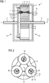
- the Figures 1 to 4 show a planetary gear 1 according to a first embodiment of the present invention.
- the planetary gear 1 has a gear housing 2, which is penetrated by an input shaft 3 and an output shaft 4 on opposite end faces.
- a central sun gear 5 with external teeth 6 on the output shaft 4 is held rotatably about a central gear rotation axis 37 in the gear housing 2.
- a ring gear 7 with an internal toothing 8, which is fixed to the gear housing 2 and surrounds the sun gear 5 is arranged in the gear housing 2, concentric with the central gear axis of rotation 37.
- a planet carrier is located on the drive shaft 3 in the gear housing 2 9 rotatably held about the central gear axis of rotation 37.
- the planet carrier 9 has a cheek 9 on a first end face of the planetary gear 1 or the planet gears 13. There is no further cheek on a second end face 32 of the planetary gear 1 or the planet gears 13.
- the cheek 9 carries the planet gears.
- the planet carrier 9 is designed such that it has only one cheek 9 on the side of the drive shaft 3.
- the planet gears are arranged between these two cheeks of the planet carrier. This is in the FIG. 1 however not shown.
- the adjustment of the bearing play of the tapered slide bearings for the double-cheeked planet carrier is complex, at the same time the components of the slide bearing must be secured against rotation on the axis. This is made more difficult by the double-walled planet carrier and the form-fit of the tapered plain bearings, since the axle is the last component to be inserted axially into the assembly of the carrier. This means that the components cannot be secured against rotation on the axis.
- the planetary gear 1 after FIG. 1 has only one cheek.
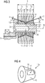
- each planet gear axis 36 is shown to improve clarity.
- the planet carrier 9 can also carry a number of planet wheel axles that deviate from three.
- a planet gear bearing 12 designed as a slide bearing, in which a planet gear 13 is rotatably mounted about a planet gear axis of rotation 36.
- the planet gears 13 have external toothings 14 which are in engagement with the internal toothing 8 of the ring gear 7 and the external toothing 6 of the sun gear 5.
- the planet gear bearing 12 has a first bearing body 12a and a second bearing body 12b.
- the planet gear axis of rotation 36 is connected to the planet carrier 9 only on one side. This results in a free end of the planet gear axis of rotation 36 with respect to the clamping.
- This assembly can now be assembled using an axial plug-in assembly. A positive fit of the tapered slide bearings can also pose no problem.
- the plain bearing body 12a (can also be referred to as a plain bearing ring) can be radially secured against rotation on the axis.
- the planet gear is then mounted axially over the free end of the planet gear axis of rotation 36 before the further bearing body 12b is slipped on axially.
- Each planet gear bearing 12 has two annular bearing bodies 12a and 12b, which are penetrated by the planet gear axis 11 and are held on the latter in a rotationally fixed manner.
- conical jacket-shaped sliding surfaces 16 are formed, each spanning an acute angle a, which is preferably between 5 ° and 40 °, with the central gear rotation axis 37.
- Bevels or the like can be provided in the axial edge regions of the sliding surfaces 16 in order to counteract the formation of edges due to wear.
- Each bearing body 12a, 12b is penetrated radially by a lubricant channel 17.
- the lubricant channel 17 is connected to an eccentric lubricant supply channel 18 which passes axially through the planet gear axis 11.
- the lubricant channel 17 opens into a lubrication pocket 19, which is designed as a flat or recess in a slightly loaded area of the sliding surface 16 of the bearing body 12a, 12b.
- the tapered ends of the bearing bodies 12a, 12b point towards one another, running surfaces 20 corresponding to the sliding surfaces 16 of the planet gear bearing 12 being formed on inner peripheral surfaces of the planet gear 13.
- a spacer ring 21 is arranged between the bearing bodies 12a, 12b of the planet gear bearing 12, which surrounds the planet gear axis 11 and defines a minimum distance between the bearing bodies 12a, 12b.
- an annular lubricant collecting groove 22 is formed, into which a plurality of lubricant channels 23 which pass through the spacer ring open.
- a central lubricant supply channel 24 is formed in the planet gear axis 11, which opens into the lubricant collecting groove 22 of the spacer ring 21.
- the central lubricant supply duct 24, the lubricant collecting groove 22 and the plurality of lubricant ducts 23 allow the planetary gear bearing 12 to be greased, which is sufficient for emergency operation of the planetary gear.
- B denotes the desired width of the planet gear bearing 12.
- the bearing bodies 12a and 12b and the spacer ring 21 initially fulfill the relationship b 1 + b 2 + b 3 > B.
- ⁇ S ⁇ b ⁇ sin ( ⁇ ) between a change in height ⁇ S of the lubricating gap 25 and an axial adjustment of the respective bearing body 12a or 12b caused by a change in width ⁇ b.
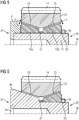
- FIG 5 shows a section of a cross-sectional view of a planet gear bearing, in which the locking ring 30 is screwed onto the planet gear axle 11 by means of a thread 33.
- the bearing bodies 12a and 12b with the spacer ring 21 lying in between are pressed onto the planet carrier 9.
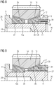
- FIG 6 shows a section of a cross-sectional view of a planetary gear bearing with a hybrid bearing body 9a. Comparing the hybrid bearing body 9a FIG 6 for example with elements FIG 5 , it becomes clear that the hybrid bearing body 9a follows the functions of the elements planet carrier 9, bearing body 12a and planet gear axis 11 FIG 5 integrated in a component 9a. This reduces complexity and can increase the rigidity of the transmission.
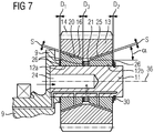
- FIG 7 shows a planet gear bearing 12 of a planetary gear 1 according to a further embodiment of the planetary gear.
- Spacer elements 26 are inserted between the bearing body 12a and the spacer ring 21 and between the bearing bodies 12a, 12b and respectively adjacent elements, such as planet carrier 9 or locking ring 30.
- the bearing bodies 12a, 12b and the spacer ring 21 first fulfill the relationship b 1 + b 2 + b 3 ⁇ B. in order to set the desired height S of the lubrication gap 25.
- b 1 , b 2 , b 3 and B are as in the in FIG 3 shown embodiment defines and D 1 , D 2 and D 3 denote the axial widths of the spacers 26th
- the axial widths of the bearing bodies 12a, 12b and the spacer ring 21 satisfy the relationship b 1 + b 2 + b 3 ⁇ B.
- spacer elements 26 of suitable thicknesses D 1 , D 2 and D 3 are inserted at the points mentioned, that the summed axial thickness D 1 + D 2 + D 3 of all inserted spacer elements 26 is equal to the difference between the bearing width B and the summed axial width b 1 + b 2 + b 3 of the bearing bodies 12a, 12b and the spacer ring 21 and the lubrication gap S has the required height S.
- FIG 8 shows in a detail a planet gear bearing 12 of a planetary gear 1 according to a further embodiment.
- the adjustable bearing body 12a is screwed onto the planet gear axis 11.
- an internal thread is formed on the adjustable bearing body 12a and a corresponding external thread is formed on the planet gear axis 11.
- This screw connection 27 allows a stepless adjustment of the axial position of the adjustable bearing body 12a on the planet gear axis 11.
- the axially fixed bearing body 12b is screwed to a bearing body holder 10 with a screw 39.
- the bearing body holder is axially fixed via the locking ring 30, which projects into the planet gear axis 11 and into the bearing body holder 10.
- the bearing body 12a When the required height S of the lubrication gap 25 is reached, the bearing body 12a is fixed in the corresponding axial position by an anti-rotation device 28. Pins, bolts or the like can be used as anti-rotation means 28. If the height S of the lubrication gap 25 changes over time due to an operational Changes wear, the adjustable bearing body 12a can be readjusted accordingly to restore the required height S of the lubrication gap 25.
- FIG. 9 shows a planet gear bearing 12 of a planetary gear 1 according to a further embodiment.
- the adjustable bearing body 12b is screwed onto the planet gear axle 11 by means of a thread 27 and secured by means of an anti-rotation device 28.
- the screw connection 27 enables the bearing body 12b to be positioned in the axial direction. Pins, bolts or the like can also be used here as anti-rotation device 28.
- the axial position of the axially fixed bearing body 12a is determined by a radial annular shoulder 29 formed on the planet gear axis 11 and serving as an axial stop.
- the required height S of the lubrication gap 25 can be set by screwing in or unscrewing the adjustable bearing body 12b. If the height S of the lubrication gap 25 of the planet gear bearing 12 has shifted as a result of operational wear, the planet gear bearing 12 can be readjusted accordingly by axially adjusting the bearing body 12b.
- the proposed methods and designs for setting an optimal height of the lubrication gap 25 of the planetary gear bearing 12 can also be combined with one another.
- the planet carrier 9 is set in rotation by the drive shaft 3. Because of the engagement of their external toothing 14 in the internal toothing 8 of the ring gear 7, the planet gears 13 roll along the inside of the ring gear 7. Due to the rotation of the planet gears 13, because of the engagement of their external toothing 14 in the external toothing 6 of the sun gear 5, the sun gear 5 and with it the output shaft 4 are rotated.
- the output shaft 4 rotates at a higher speed than the drive shaft 3 because the planet gears 13 have a smaller circumference than the circle which the planet gear rotation axes 36 describe as they rotate about the central gear rotation axis 37 of the planetary gear 1.
- lubricant is continuously supplied to it through the central lubricant supply channel 24.
- the lubricant is first distributed in the lubricant collecting groove 22 of the spacer ring 21 and then flows through the at least one lubricant channel 23 in the direction of the lubricating gap 25 (see FIG 3 ).
- An advantage of the planetary gear 1 described is that, in contrast to cylindrical slide bearings, no additional axial slide bearings have to be provided in order to fix the planet gear 13 in the axial direction. This accordingly makes the machining of additional axial sliding surfaces superfluous.
- Another advantage of the plain bearing described is the simple adjustment or readjustment of the height S of the lubrication gap 25, which allows a greater component tolerance in the manufacture of the components required for the planet gear bearing. Overall, when using such a planetary gear, cost advantages can be achieved from lower manufacturing costs and an increased service life of the planetary gear bearings 12 due to the adjustment options.
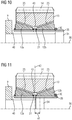
- FIG 10 shows a section of a cross-sectional view of a planetary gear bearing with a Flex-Pin 34, a tapered plain bearing with a classic Flex-Pin.
- the flex pin 37 carries a hollow cylinder 35.
- the hollow cylinder 35 carries the bearing bodies 12a and 12b and the spacer ring 21.
- a groove channel 43 is formed above the spacer ring 21.
- the bearing body 12a is positioned axially by a stop 40.
- the locking ring 30 clamps the bearing body 12a and 12b, as well as the spacer ring 21.
- FIG 11 shows a section of a cross-sectional view of a planetary gear bearing with a shortened Flex pin 34.
- the flex pin 34 ends in comparison to the flex pin 34 FIG 10 in an axially central region of the hollow cylinder 35.
- the flex pin 34 is offset from the center 42 of the planet gear 13 by the offset 41. In this way, a more symmetrical force distribution can be achieved. Due to the lower mass of the Flex-Pin 34 FIG 11 inertia is also reduced.
- FIG 12 shows a flex pin 34 as an axis for the planet gear with an integrated lubricant line 38.
- the lubricant line 38 (for example for the supply with an oil) also penetrates the hollow cylinder 35 and ends in the groove channel 43.
- the lubricant line 38 is to the end piece 44 of the flex Pin 34 offset.
- the offsets 41a and 41b are different.
- the end piece 44 completely covers the groove channel 42.
- the cardan joint with the hollow cylinder (sleeve) can be offset 41 (see FIG 11 ) of the connection from the axis (Flex-Pin) to the hollow cylinder (Flex-Pin sleeve) can be adjusted and adjusted depending on the degree of deformation.
- FIG. 13 shows a section of a cross-sectional view of a planet gear bearing with asymmetrical bearing bodies 12a and 12b.
- the bearing body 12a With its axis length b1, the bearing body 12a has an axis length that is different from the bearing body 12b (with the axis length b2).
- the groove channel 43 is offset to the center 42 of the planet gear by the offset 41.
- the first lubrication gap 25a has a first angle ⁇ 1 to the planet gear axis 36.
- the second lubrication gap 25b has a second angle ⁇ 2 to the planet gear axis 36.
- the taper angle ⁇ 1 and ⁇ 2 can be different for both tapered plain bearings.
- the left slide bearing with the bearing body 12a is made larger than the right slide bearing with the Bearing body 12b. This can also serve as an adjustment option to compensate for asymmetrical deformations due to uneven loading.
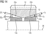
- FIG 14 shows a section of a cross-sectional view of a planet gear bearing with a lubrication gap of different heights 45a and 45b.
- the first lubrication gap 25a has a height 45a that increases from the inside to the outside.
- the second lubrication gap 25b also has a height 45b which increases from the inside to the outside.
- the minimum heights of the lubrication gaps 25a and 25b are the same.
- the maximum heights of the lubrication gaps 25a and 25b are different. This results in an asymmetrical tapered slide bearing with angle correction.
- the taper angles of the respective slide bearing functional surfaces are designed differently. This can be done as a geometric correction of the plain bearings if the deformations are large enough.
Claims (21)
- Engrenage (1) épicycloïdal, notamment pour une éolienne, comprenant un carter (2) d'engrenage, une roue (5) solaire centrale, qui est maintenue tournante dans le carter (2) de l'engrenage autour d'un axe (37) de rotation de l'engrenage et qui porte une denture (6) extérieure, une roue (7) à denture intérieure, qui est disposée concentriquement à l'axe (37) central de rotation de l'engrenage dans le carter (2) de l'engrenage et qui a une denture (8) intérieure, un porte-satellite (9) à un flasque, qui est monté tournant dans le carter (2) de l'engrenage autour de l'axe (37) central de rotation de l'engrenage, et plusieurs roues (13) satellites, qui sont montées tournantes au moyen de paliers (12) de roue satellite conformés en paliers lisses sur le porte-satellite (9) autour d'axes (36) de rotation de roue satellite et qui ont des dentures (14) extérieures, qui engrènent avec la denture (8) intérieure de la roue (7) à denture intérieure et avec la denture (6) extérieure de la roue (5) solaire, chaque palier (12) de roue satellite ayant deux pièces (12a, 12b) de palier annulaires, au moins l'une des pièces (12b) de palier annulaires étant traversée par un axe (11) de roue satellite et en étant solidaire en rotation, dans lequel, sur la surface périphérique extérieure de la pièces (12a, 12b) de palier, sont constituées des surfaces de glissement en forme de surfaces latérales de cône, de manière à ce que les extrémités rétrécies des pièces (12a, 12b) de palier soient tournées l'une vers l'autre, et dans lequel, sur des surfaces périphériques intérieures de la roue (13) satellite, sont constituées des surfaces (20a, 20b) de roulement correspondant aux surfaces de glissement du palier (12) de la roue satellite.
- Engrenage (1) épicycloïdal suivant la revendication 1, comprenant un premier côté (31) frontal et un deuxième côté (32) frontal, le porte-satellite (9) à un flasque étant dans la partie du premier côté (31) frontal, la au moins une pièce (12b) de palier annulaire étant sur le deuxième côté (32) frontal découplée mécaniquement d'une autre roue (13) satellite.
- Engrenage (1) épicycloïdal suivant la revendication 1 ou 2, dans lequel les pièces (12a, 12b) de palier sont disposées en étant à distance axialement.
- Engrenage (1) épicycloïdal suivant l'une des revendications précédentes, dans lequel un anneau (30) de blocage bloque au moins une pièce (12a, 12b) de palier sur l'axe (11) de la roue satellite.
- Engrenage (1) épicycloïdal suivant l'une des revendications précédentes, dans lequel l'axe (11) de la roue satellite est un flex-pin (34) ayant un cylindre (35) creux.
- Engrenage (1) épicycloïdal suivant la revendication 5, dans lequel le flex-pin (34) a un conduit (38) de lubrification.
- Engrenage (1) épicycloïdal suivant l'une des revendications précédentes, dans lequel, entre les surfaces de glissement du palier (12) de la roue satellite et les surfaces (20a, 20b) de roulement correspondantes de la roue (13) satellite montée, il y a un intervalle de lubrification, un premier de ces intervalles (25a) de lubrification étant différent du deuxième de ces intervalles de lubrification.
- Engrenage (1) épicycloïdal suivant la revendication 7, dans lequel le premier intervalle de lubrification et le deuxième intervalle de lubrification ont une longueur axiale différente.
- Engrenage (1) épicycloïdal suivant la revendication 7 ou 8, dans lequel au moins l'un des intervalles de lubrification a une hauteur axiale différente.
- Engrenage (1) épicycloïdal suivant l'une des revendications 7 à 9, dans lequel le premier intervalle de lubrification a une inclinaison, par rapport à l'axe (36) de rotation de la roue (13) satellite, différente de celle du deuxième intervalle de lubrification.
- Engrenage (1) épicycloïdal suivant l'une des revendications précédentes, dans lequel au moins une pièce (12a, 12b) de palier est réglable dans la direction axiale, afin de régler un intervalle (25) de lubrification de hauteur (S) définie entre les surfaces de glissement du palier (12) de la roue satellite et les surfaces (20) de roulement correspondantes de la roue (13) satellite montée.
- Engrenage (1) épicycloïdal suivant l'une des revendications précédentes, dans lequel exactement une pièce (12a, 12b) de palier est réglable et l'autre pièce (12a, 12b) de palier a une position fixe axialement.
- Engrenage (1) épicycloïdal suivant la revendication 12, dans lequel la position axiale de la pièce (12a, 12b) de palier fixe axialement est définie par une butée (40) axiale, notamment par un épaulement (25) annulaire radial, constitué sur l'axe (11) de la roue satellite, du porte-satellite (9).
- Engrenage (1) épicycloïdal suivant l'une des revendications 12 à 13, caractérisé en ce que des moyens d'ajustement, pour le réglage axial, sont associés à la pièce (12a, 12b) de palier réglable.
- Engrenage (1) épicycloïdal suivant l'une des revendications 12 à 14, caractérisé en ce que la pièce (12a, 12b) de palier réglable est vissée sur l'axe (11) de la roue satellite.
- Engrenage (1) épicycloïdal suivant la revendication 15, caractérisé en ce qu'il est prévu une sécurité (28) à la torsion, au moyen de laquelle la pièce (12a, 12b) de palier réglable peut être fixée axialement.
- Engrenage (1) épicycloïdal suivant l'une des revendications précédentes, caractérisé en ce que, dans chaque surface de glissement, est constituée au moins une poche (19) de lubrification, dans laquelle débouche un conduit (17) de lubrification, qui traverse radialement la pièce (12a, 12b) de palier, le conduit (17) de lubrification communiquant avec un conduit (18) excentré d'apport de lubrifiant, qui est constitué dans l'axe (11) de la roue satellite et qui y passe axialement.
- Engrenage (1) épicycloïdal suivant l'une des revendications précédentes, caractérisé en ce que, entre les pièces (12a, 12b) de palier, est disposé un anneau (21) d'entretoisement, qui entoure l'axe (11) de la roue satellite et définit une distance axiale minimum entre les pièces (12a, 12b) de palier.
- Engrenage (1) épicycloïdal suivant la revendication 18, caractérisé en ce que, sur une surface périphérique intérieure de l'anneau (21) d'entretoisement, est constituée une rainure (22) annulaire de collecte de lubrifiant.
- Engrenage (1) épicycloïdal suivant la revendication 19, caractérisé en ce que, dans l'anneau (21) d'entretoisement, est constituée une pluralité de conduits (23) de lubrification, qui débouchent dans la rainure (22) collectrice de lubrifiant.
- Engrenage (1) épicycloïdal suivant la revendication 20, caractérisé en ce que, dans l'axe (11) de la roue satellite, est constitué un conduit (24) central d'apport de lubrifiant, qui débouche dans la rainure (22) collectrice de lubrifiant de l'anneau (21) d'entretoisement.
Priority Applications (7)
| Application Number | Priority Date | Filing Date | Title |
|---|---|---|---|
| ES16187064T ES2814177T3 (es) | 2016-09-02 | 2016-09-02 | Engranaje planetario |
| EP16187064.7A EP3290751B2 (fr) | 2016-09-02 | 2016-09-02 | Train épicycloïdal |
| CN201780053419.5A CN109661531B (zh) | 2016-09-02 | 2017-08-22 | 行星传动装置 |
| EP17761049.0A EP3507526B1 (fr) | 2016-09-02 | 2017-08-22 | Train épicycloïdal |
| ES17761049T ES2925386T3 (es) | 2016-09-02 | 2017-08-22 | Engranaje planetario |
| US16/330,248 US10844905B2 (en) | 2016-09-02 | 2017-08-22 | Planetary transmission |
| PCT/EP2017/071140 WO2018041671A1 (fr) | 2016-09-02 | 2017-08-22 | Boîte de vitesses à trains épicycloïdaux |
Applications Claiming Priority (1)
| Application Number | Priority Date | Filing Date | Title |
|---|---|---|---|
| EP16187064.7A EP3290751B2 (fr) | 2016-09-02 | 2016-09-02 | Train épicycloïdal |
Publications (3)
| Publication Number | Publication Date |
|---|---|
| EP3290751A1 EP3290751A1 (fr) | 2018-03-07 |
| EP3290751B1 true EP3290751B1 (fr) | 2020-06-10 |
| EP3290751B2 EP3290751B2 (fr) | 2023-12-13 |
Family
ID=56853536
Family Applications (2)
| Application Number | Title | Priority Date | Filing Date |
|---|---|---|---|
| EP16187064.7A Active EP3290751B2 (fr) | 2016-09-02 | 2016-09-02 | Train épicycloïdal |
| EP17761049.0A Active EP3507526B1 (fr) | 2016-09-02 | 2017-08-22 | Train épicycloïdal |
Family Applications After (1)
| Application Number | Title | Priority Date | Filing Date |
|---|---|---|---|
| EP17761049.0A Active EP3507526B1 (fr) | 2016-09-02 | 2017-08-22 | Train épicycloïdal |
Country Status (5)
| Country | Link |
|---|---|
| US (1) | US10844905B2 (fr) |
| EP (2) | EP3290751B2 (fr) |
| CN (1) | CN109661531B (fr) |
| ES (2) | ES2814177T3 (fr) |
| WO (1) | WO2018041671A1 (fr) |
Families Citing this family (16)
| Publication number | Priority date | Publication date | Assignee | Title |
|---|---|---|---|---|
| AT519288B1 (de) * | 2016-10-21 | 2018-07-15 | Miba Gleitlager Austria Gmbh | Lagerelement |
| DE102017222901A1 (de) * | 2017-12-15 | 2019-06-19 | Zf Friedrichshafen Ag | Planetengetriebestufe mit einer Gleitlageranordnung, insbesondere für eine Planetenradlagerung in einem Windkraftgetriebe |
| US10683773B2 (en) * | 2018-05-25 | 2020-06-16 | Pratt & Whitney Canada Corp. | Planetary gearbox having compliant journal bearings |
| DE102018214083A1 (de) * | 2018-08-21 | 2020-02-27 | Zf Friedrichshafen Ag | Planetengetriebe für eine Windkraftanlage |
| FR3088979B1 (fr) * | 2018-11-23 | 2021-06-18 | Safran Trans Systems | Porte-satellites pour un reducteur mecanique de turbomachine d’aeronef |
| FR3088980B1 (fr) * | 2018-11-23 | 2021-01-08 | Safran Trans Systems | Noyau de lubrification et de refroidissement pour un reducteur mecanique de turbomachine d’aeronef |
| EP3670967B1 (fr) * | 2018-12-17 | 2021-08-18 | Moventas Gears Oy | Arbre de roue planétaire pour engrenage planétaire |
| AT522476B1 (de) * | 2019-05-21 | 2020-11-15 | Miba Gleitlager Austria Gmbh | Gondel für eine Windkraftanlage |
| CN110611168B (zh) * | 2019-09-21 | 2020-11-20 | 深圳市锦凌电子有限公司 | 一种5g通信的多天线校准装置 |
| EP3798470B1 (fr) * | 2019-09-27 | 2023-03-08 | Flender GmbH | Engrenage épicycloïdal à alimentation en lubrifiant améliorée, chaîne cinématique et éolienne |
| US11149786B2 (en) | 2020-02-28 | 2021-10-19 | Pratt & Whitney Canada Corp. | Carrier journal with anti-rotation feature |
| CN111828558B (zh) * | 2020-08-10 | 2022-09-20 | 重庆大学 | 一种可调隙少齿差减速器 |
| EP4047228A1 (fr) * | 2021-02-23 | 2022-08-24 | Flender GmbH | Agencement des roulements, pignon de générateur, centrale éolienne et produit programme informatique |
| GB202103169D0 (en) * | 2021-03-08 | 2021-04-21 | Rolls Royce Plc | Planetary gearbox |
| US11542842B2 (en) * | 2021-05-24 | 2023-01-03 | Borgwarner Inc. | Electrically-actuated camshaft phasers with tapered features |
| DE102021122300A1 (de) * | 2021-08-27 | 2023-03-02 | Rolls-Royce Deutschland Ltd & Co Kg | Planetengetriebe |
Citations (14)
| Publication number | Priority date | Publication date | Assignee | Title |
|---|---|---|---|---|
| FR915604A (fr) | 1944-09-11 | 1946-11-13 | Perfectionnements apportés aux paliers ou coussinets | |
| US2721773A (en) | 1953-05-11 | 1955-10-25 | Jr Vincent Gentile | Slip sleeve bearing |
| DE1500451A1 (de) | 1964-02-07 | 1969-05-08 | Nat Res Dev | Getriebe |
| US3476451A (en) | 1966-02-07 | 1969-11-04 | Everett H Schwartzman | Fluid bearing system |
| DE2249248A1 (de) | 1971-10-08 | 1973-04-12 | Vandervell Products Ltd | Lagerauskleidung und verfahren zu deren herstellung |
| US3844182A (en) | 1972-08-22 | 1974-10-29 | Cam Gears Ltd | Rack and pinion assemblies |
| US3984152A (en) | 1970-11-13 | 1976-10-05 | Haines Charles E | Frusto-conical laminar bearings |
| DE7826851U1 (de) | 1978-09-09 | 1979-01-04 | Fichtel & Sachs Ag, 8720 Schweinfurt | Freilaufnabe mit ruecktrittbremse |
| WO2007028965A1 (fr) | 2005-09-06 | 2007-03-15 | Orbital2 Limited | Ensemble d’engrenages planétaires |
| US20110082005A1 (en) | 2008-06-13 | 2011-04-07 | The Timken Company | Epicyclic Gear System With Flexpins And Helical Gearing |
| EP2383480A1 (fr) | 2010-04-30 | 2011-11-02 | Winergy AG | Train épicycloïdal pour une éolienne |
| US20120114488A1 (en) | 2008-05-20 | 2012-05-10 | Urs Giger | Wind power plant, transmission for a wind power plant and flexpin |
| CN103697059A (zh) | 2013-12-09 | 2014-04-02 | 浙江大学 | 承受双向轴向载荷的滑动轴承 |
| US20150055246A1 (en) | 2013-08-26 | 2015-02-26 | Nidec Corporation | Spindle motor and disk drive apparatus |
Family Cites Families (23)
| Publication number | Priority date | Publication date | Assignee | Title |
|---|---|---|---|---|
| US5455778A (en) | 1987-05-29 | 1995-10-03 | Ide; Russell D. | Bearing design analysis apparatus and method |
| DE19534791C2 (de) * | 1995-09-20 | 1997-11-13 | Ford Werke Ag | Planetenradträgeranordnung mit Axialabstützung |
| GB0002126D0 (en) * | 2000-01-31 | 2000-03-22 | Hanson Transmissions Internati | Planetary gear stage |
| DE10064815A1 (de) * | 2000-12-22 | 2002-07-11 | Zahnradfabrik Friedrichshafen | Planetengetriebe |
| JP2002250343A (ja) * | 2001-02-21 | 2002-09-06 | Minebea Co Ltd | 特殊軸受装置 |
| JP2006170413A (ja) * | 2004-12-20 | 2006-06-29 | Seisa Gear Ltd | はすば遊星減速機の軸受装置 |
| US7662059B2 (en) | 2006-10-18 | 2010-02-16 | United Technologies Corporation | Lubrication of windmilling journal bearings |
| US7538446B2 (en) * | 2007-06-21 | 2009-05-26 | General Electric Company | Gear integrated generator for wind turbine |
| CN201381944Y (zh) * | 2009-04-02 | 2010-01-13 | 杭州前进风电齿轮箱有限公司 | 风力发电变桨减速齿轮箱 |
| US8246503B2 (en) | 2009-06-10 | 2012-08-21 | United Technologies Corporation | Epicyclic gear system with improved lubrication system |
| CN201714590U (zh) * | 2010-03-31 | 2011-01-19 | 南京高速齿轮制造有限公司 | 风力发电机用增速齿轮箱 |
| JP5511968B2 (ja) | 2010-08-31 | 2014-06-04 | 三菱重工業株式会社 | 遊星歯車機構、風力発電装置、及び遊星歯車機構のキャリアの製造方法 |
| US8491435B2 (en) * | 2011-08-26 | 2013-07-23 | General Electric Company | Journal bearing for use in epicyclical gearbox and method of facilitating hydrodynamic oil flow in the journal bearing |
| CN103557293B (zh) * | 2013-07-01 | 2017-03-15 | 陈伟 | 大型筒状铸造机座的软启动减速装置 |
| DE102013220063A1 (de) * | 2013-10-02 | 2015-04-02 | Schaeffler Technologies Gmbh & Co. Kg | Planetenradlageranordnung |
| BR102014026410A2 (pt) * | 2013-11-07 | 2016-10-04 | Skf Ab | disposição de mancal para aplicação de maquinário de fluido |
| DE102014205980A1 (de) * | 2014-03-31 | 2015-10-01 | Schaeffler Technologies AG & Co. KG | Planetentrieb mit einem Planetenrad, das mittels zwei Planetenbolzen in einem Planetenträger gelagert ist |
| EP2933483A1 (fr) * | 2014-04-15 | 2015-10-21 | Siemens Aktiengesellschaft | Système d'entraînement d'une éolienne |
| CN203962939U (zh) * | 2014-06-30 | 2014-11-26 | 南车戚墅堰机车车辆工艺研究所有限公司 | 一种风电齿轮箱的低速轴支撑结构 |
| DE102014214331A1 (de) * | 2014-07-23 | 2016-01-28 | Schaeffler Technologies AG & Co. KG | Planetengetriebe |
| CN204591990U (zh) * | 2015-03-18 | 2015-08-26 | 河北省轴承产业技术研究院 | 一种自润滑单列圆锥轴承 |
| DK3091255T3 (da) * | 2015-05-07 | 2020-02-10 | Flender Gmbh | Planetgear |
| WO2017073325A1 (fr) * | 2015-10-29 | 2017-05-04 | Ntn株式会社 | Procédé de fabrication de bague de roulement, roulement à rouleaux coniques à rangées multiples et son procédé de fabrication |
-
2016
- 2016-09-02 EP EP16187064.7A patent/EP3290751B2/fr active Active
- 2016-09-02 ES ES16187064T patent/ES2814177T3/es active Active
-
2017
- 2017-08-22 WO PCT/EP2017/071140 patent/WO2018041671A1/fr unknown
- 2017-08-22 EP EP17761049.0A patent/EP3507526B1/fr active Active
- 2017-08-22 ES ES17761049T patent/ES2925386T3/es active Active
- 2017-08-22 CN CN201780053419.5A patent/CN109661531B/zh active Active
- 2017-08-22 US US16/330,248 patent/US10844905B2/en active Active
Patent Citations (14)
| Publication number | Priority date | Publication date | Assignee | Title |
|---|---|---|---|---|
| FR915604A (fr) | 1944-09-11 | 1946-11-13 | Perfectionnements apportés aux paliers ou coussinets | |
| US2721773A (en) | 1953-05-11 | 1955-10-25 | Jr Vincent Gentile | Slip sleeve bearing |
| DE1500451A1 (de) | 1964-02-07 | 1969-05-08 | Nat Res Dev | Getriebe |
| US3476451A (en) | 1966-02-07 | 1969-11-04 | Everett H Schwartzman | Fluid bearing system |
| US3984152A (en) | 1970-11-13 | 1976-10-05 | Haines Charles E | Frusto-conical laminar bearings |
| DE2249248A1 (de) | 1971-10-08 | 1973-04-12 | Vandervell Products Ltd | Lagerauskleidung und verfahren zu deren herstellung |
| US3844182A (en) | 1972-08-22 | 1974-10-29 | Cam Gears Ltd | Rack and pinion assemblies |
| DE7826851U1 (de) | 1978-09-09 | 1979-01-04 | Fichtel & Sachs Ag, 8720 Schweinfurt | Freilaufnabe mit ruecktrittbremse |
| WO2007028965A1 (fr) | 2005-09-06 | 2007-03-15 | Orbital2 Limited | Ensemble d’engrenages planétaires |
| US20120114488A1 (en) | 2008-05-20 | 2012-05-10 | Urs Giger | Wind power plant, transmission for a wind power plant and flexpin |
| US20110082005A1 (en) | 2008-06-13 | 2011-04-07 | The Timken Company | Epicyclic Gear System With Flexpins And Helical Gearing |
| EP2383480A1 (fr) | 2010-04-30 | 2011-11-02 | Winergy AG | Train épicycloïdal pour une éolienne |
| US20150055246A1 (en) | 2013-08-26 | 2015-02-26 | Nidec Corporation | Spindle motor and disk drive apparatus |
| CN103697059A (zh) | 2013-12-09 | 2014-04-02 | 浙江大学 | 承受双向轴向载荷的滑动轴承 |
Non-Patent Citations (2)
| Title |
|---|
| A. CZABAN: "The Influence oft he Microgrooves on the Hydrodynamic Pressure Distribution and Load Carrying Capacity oft he Conical Slide Bearing", JOURNAL OF KONES POWERTRAIN AND TRANSPORT, vol. 19, no. 3, 2012, pages 85 - 91, XP055788991 |
| M. KOPROWSKI: "An Analysis of Lubricating Medium Flow trougth Unsymmetrical Lubricating Gap of Conical Slide Bearing", POLISH MARITIME RESEARCH, vol. 17, no. 54, 2007 |
Also Published As
| Publication number | Publication date |
|---|---|
| ES2925386T3 (es) | 2022-10-17 |
| ES2814177T3 (es) | 2021-03-26 |
| CN109661531B (zh) | 2021-12-21 |
| US10844905B2 (en) | 2020-11-24 |
| EP3507526A1 (fr) | 2019-07-10 |
| WO2018041671A1 (fr) | 2018-03-08 |
| US20190203768A1 (en) | 2019-07-04 |
| CN109661531A (zh) | 2019-04-19 |
| EP3290751A1 (fr) | 2018-03-07 |
| EP3290751B2 (fr) | 2023-12-13 |
| EP3507526B1 (fr) | 2022-07-20 |
Similar Documents
| Publication | Publication Date | Title |
|---|---|---|
| EP3290751B1 (fr) | Train épicycloïdal | |
| EP3091255B1 (fr) | Train épicycloïdal | |
| EP2602512B1 (fr) | Vis de réglage de laminoir planétaire | |
| EP3247923B1 (fr) | Transmission et procédé permettant de régler le jeu de torsion de ladite transmission | |
| EP3371482B1 (fr) | Transmission comportant un flasque de butée | |
| EP1429054A2 (fr) | Engrenage planétaire | |
| WO1998051943A1 (fr) | Boite planetaire | |
| EP2693079B1 (fr) | Train épicycloïdal et appareil de manipulation équipé d'un tel train épicycloïdal | |
| WO2009030220A2 (fr) | Palier de rotor pour une éolienne | |
| WO2018059984A1 (fr) | Multiplicateur planétaire à rondelles de friction | |
| EP1807633A1 (fr) | Cage a tourillon, notamment pour roulements a rouleaux radiaux ou axiaux de grande taille | |
| WO2018059982A1 (fr) | Multiplicateur planétaire à rondelles de friction | |
| EP3230627A1 (fr) | Satellite étagé | |
| AT518787B1 (de) | Zahnradanordnung | |
| EP3982005B1 (fr) | Engrenage coaxial | |
| DE102019201552A1 (de) | Lagerung eines Planetenrades auf einem mit einem Planetenträger verbundenen Planetenbolzen und Verfahren zur Montage eines Planetenrades auf einem Planetenbolzen | |
| WO2023237143A1 (fr) | Dispositif de transmission pourvu d'un réducteur sans jeu | |
| EP1831590B1 (fr) | Dispositif, notamment engrenage planetaire, comprenant un corps de base en anneau | |
| WO2006058743A1 (fr) | Transmission | |
| EP2115325A2 (fr) | Différentiel à répartition du couple pour un véhicule automobile | |
| DE102015210684B4 (de) | Fixierung von Planetenlagern | |
| DE102021134205B4 (de) | Getriebeanordnung | |
| DE102022130444B4 (de) | Wellenmodul, Verfahren zur Montage eines Wellenmoduls und Getriebevorrichtung | |
| DE3641769A1 (de) | Antriebsanordnung | |
| WO2023174471A1 (fr) | Module d'arbre et procédé d'installation d'un module d'arbre |
Legal Events
| Date | Code | Title | Description |
|---|---|---|---|
| PUAI | Public reference made under article 153(3) epc to a published international application that has entered the european phase |
Free format text: ORIGINAL CODE: 0009012 |
|
| STAA | Information on the status of an ep patent application or granted ep patent |
Free format text: STATUS: THE APPLICATION HAS BEEN PUBLISHED |
|
| AK | Designated contracting states |
Kind code of ref document: A1 Designated state(s): AL AT BE BG CH CY CZ DE DK EE ES FI FR GB GR HR HU IE IS IT LI LT LU LV MC MK MT NL NO PL PT RO RS SE SI SK SM TR |
|
| AX | Request for extension of the european patent |
Extension state: BA ME |
|
| STAA | Information on the status of an ep patent application or granted ep patent |
Free format text: STATUS: REQUEST FOR EXAMINATION WAS MADE |
|
| 17P | Request for examination filed |
Effective date: 20180904 |
|
| RBV | Designated contracting states (corrected) |
Designated state(s): AL AT BE BG CH CY CZ DE DK EE ES FI FR GB GR HR HU IE IS IT LI LT LU LV MC MK MT NL NO PL PT RO RS SE SI SK SM TR |
|
| RIC1 | Information provided on ipc code assigned before grant |
Ipc: F16C 33/10 20060101ALI20191217BHEP Ipc: F03D 15/00 20160101ALI20191217BHEP Ipc: F16H 57/08 20060101AFI20191217BHEP Ipc: F16C 25/02 20060101ALI20191217BHEP Ipc: F16C 17/10 20060101ALI20191217BHEP |
|
| GRAP | Despatch of communication of intention to grant a patent |
Free format text: ORIGINAL CODE: EPIDOSNIGR1 |
|
| STAA | Information on the status of an ep patent application or granted ep patent |
Free format text: STATUS: GRANT OF PATENT IS INTENDED |
|
| INTG | Intention to grant announced |
Effective date: 20200128 |
|
| GRAS | Grant fee paid |
Free format text: ORIGINAL CODE: EPIDOSNIGR3 |
|
| GRAA | (expected) grant |
Free format text: ORIGINAL CODE: 0009210 |
|
| STAA | Information on the status of an ep patent application or granted ep patent |
Free format text: STATUS: THE PATENT HAS BEEN GRANTED |
|
| AK | Designated contracting states |
Kind code of ref document: B1 Designated state(s): AL AT BE BG CH CY CZ DE DK EE ES FI FR GB GR HR HU IE IS IT LI LT LU LV MC MK MT NL NO PL PT RO RS SE SI SK SM TR |
|
| REG | Reference to a national code |
Ref country code: GB Ref legal event code: FG4D Free format text: NOT ENGLISH |
|
| REG | Reference to a national code |
Ref country code: CH Ref legal event code: EP Ref country code: AT Ref legal event code: REF Ref document number: 1279448 Country of ref document: AT Kind code of ref document: T Effective date: 20200615 |
|
| REG | Reference to a national code |
Ref country code: DE Ref legal event code: R096 Ref document number: 502016010173 Country of ref document: DE |
|
| REG | Reference to a national code |
Ref country code: IE Ref legal event code: FG4D Free format text: LANGUAGE OF EP DOCUMENT: GERMAN |
|
| REG | Reference to a national code |
Ref country code: SE Ref legal event code: TRGR |
|
| REG | Reference to a national code |
Ref country code: LT Ref legal event code: MG4D |
|
| PG25 | Lapsed in a contracting state [announced via postgrant information from national office to epo] |
Ref country code: FI Free format text: LAPSE BECAUSE OF FAILURE TO SUBMIT A TRANSLATION OF THE DESCRIPTION OR TO PAY THE FEE WITHIN THE PRESCRIBED TIME-LIMIT Effective date: 20200610 Ref country code: GR Free format text: LAPSE BECAUSE OF FAILURE TO SUBMIT A TRANSLATION OF THE DESCRIPTION OR TO PAY THE FEE WITHIN THE PRESCRIBED TIME-LIMIT Effective date: 20200911 Ref country code: NO Free format text: LAPSE BECAUSE OF FAILURE TO SUBMIT A TRANSLATION OF THE DESCRIPTION OR TO PAY THE FEE WITHIN THE PRESCRIBED TIME-LIMIT Effective date: 20200910 Ref country code: LT Free format text: LAPSE BECAUSE OF FAILURE TO SUBMIT A TRANSLATION OF THE DESCRIPTION OR TO PAY THE FEE WITHIN THE PRESCRIBED TIME-LIMIT Effective date: 20200610 |
|
| REG | Reference to a national code |
Ref country code: NL Ref legal event code: MP Effective date: 20200610 |
|
| PG25 | Lapsed in a contracting state [announced via postgrant information from national office to epo] |
Ref country code: BG Free format text: LAPSE BECAUSE OF FAILURE TO SUBMIT A TRANSLATION OF THE DESCRIPTION OR TO PAY THE FEE WITHIN THE PRESCRIBED TIME-LIMIT Effective date: 20200910 Ref country code: RS Free format text: LAPSE BECAUSE OF FAILURE TO SUBMIT A TRANSLATION OF THE DESCRIPTION OR TO PAY THE FEE WITHIN THE PRESCRIBED TIME-LIMIT Effective date: 20200610 Ref country code: HR Free format text: LAPSE BECAUSE OF FAILURE TO SUBMIT A TRANSLATION OF THE DESCRIPTION OR TO PAY THE FEE WITHIN THE PRESCRIBED TIME-LIMIT Effective date: 20200610 Ref country code: LV Free format text: LAPSE BECAUSE OF FAILURE TO SUBMIT A TRANSLATION OF THE DESCRIPTION OR TO PAY THE FEE WITHIN THE PRESCRIBED TIME-LIMIT Effective date: 20200610 |
|
| PG25 | Lapsed in a contracting state [announced via postgrant information from national office to epo] |
Ref country code: AL Free format text: LAPSE BECAUSE OF FAILURE TO SUBMIT A TRANSLATION OF THE DESCRIPTION OR TO PAY THE FEE WITHIN THE PRESCRIBED TIME-LIMIT Effective date: 20200610 Ref country code: NL Free format text: LAPSE BECAUSE OF FAILURE TO SUBMIT A TRANSLATION OF THE DESCRIPTION OR TO PAY THE FEE WITHIN THE PRESCRIBED TIME-LIMIT Effective date: 20200610 |
|
| PG25 | Lapsed in a contracting state [announced via postgrant information from national office to epo] |
Ref country code: EE Free format text: LAPSE BECAUSE OF FAILURE TO SUBMIT A TRANSLATION OF THE DESCRIPTION OR TO PAY THE FEE WITHIN THE PRESCRIBED TIME-LIMIT Effective date: 20200610 Ref country code: SM Free format text: LAPSE BECAUSE OF FAILURE TO SUBMIT A TRANSLATION OF THE DESCRIPTION OR TO PAY THE FEE WITHIN THE PRESCRIBED TIME-LIMIT Effective date: 20200610 Ref country code: CZ Free format text: LAPSE BECAUSE OF FAILURE TO SUBMIT A TRANSLATION OF THE DESCRIPTION OR TO PAY THE FEE WITHIN THE PRESCRIBED TIME-LIMIT Effective date: 20200610 Ref country code: RO Free format text: LAPSE BECAUSE OF FAILURE TO SUBMIT A TRANSLATION OF THE DESCRIPTION OR TO PAY THE FEE WITHIN THE PRESCRIBED TIME-LIMIT Effective date: 20200610 Ref country code: PT Free format text: LAPSE BECAUSE OF FAILURE TO SUBMIT A TRANSLATION OF THE DESCRIPTION OR TO PAY THE FEE WITHIN THE PRESCRIBED TIME-LIMIT Effective date: 20201012 |
|
| PG25 | Lapsed in a contracting state [announced via postgrant information from national office to epo] |
Ref country code: PL Free format text: LAPSE BECAUSE OF FAILURE TO SUBMIT A TRANSLATION OF THE DESCRIPTION OR TO PAY THE FEE WITHIN THE PRESCRIBED TIME-LIMIT Effective date: 20200610 Ref country code: SK Free format text: LAPSE BECAUSE OF FAILURE TO SUBMIT A TRANSLATION OF THE DESCRIPTION OR TO PAY THE FEE WITHIN THE PRESCRIBED TIME-LIMIT Effective date: 20200610 Ref country code: IS Free format text: LAPSE BECAUSE OF FAILURE TO SUBMIT A TRANSLATION OF THE DESCRIPTION OR TO PAY THE FEE WITHIN THE PRESCRIBED TIME-LIMIT Effective date: 20201010 |
|
| REG | Reference to a national code |
Ref country code: DE Ref legal event code: R026 Ref document number: 502016010173 Country of ref document: DE |
|
| PLBI | Opposition filed |
Free format text: ORIGINAL CODE: 0009260 |
|
| REG | Reference to a national code |
Ref country code: ES Ref legal event code: FG2A Ref document number: 2814177 Country of ref document: ES Kind code of ref document: T3 Effective date: 20210326 |
|
| 26 | Opposition filed |
Opponent name: ZF FRIEDRICHSHAFEN AG Effective date: 20210310 |
|
| PG25 | Lapsed in a contracting state [announced via postgrant information from national office to epo] |
Ref country code: DK Free format text: LAPSE BECAUSE OF FAILURE TO SUBMIT A TRANSLATION OF THE DESCRIPTION OR TO PAY THE FEE WITHIN THE PRESCRIBED TIME-LIMIT Effective date: 20200610 |
|
| REG | Reference to a national code |
Ref country code: CH Ref legal event code: PL |
|
| REG | Reference to a national code |
Ref country code: DE Ref legal event code: R082 Ref document number: 502016010173 Country of ref document: DE Representative=s name: MICHALSKI HUETTERMANN & PARTNER PATENTANWAELTE, DE |
|
| PG25 | Lapsed in a contracting state [announced via postgrant information from national office to epo] |
Ref country code: SI Free format text: LAPSE BECAUSE OF FAILURE TO SUBMIT A TRANSLATION OF THE DESCRIPTION OR TO PAY THE FEE WITHIN THE PRESCRIBED TIME-LIMIT Effective date: 20200610 |
|
| PLAX | Notice of opposition and request to file observation + time limit sent |
Free format text: ORIGINAL CODE: EPIDOSNOBS2 |
|
| REG | Reference to a national code |
Ref country code: BE Ref legal event code: MM Effective date: 20200930 |
|
| PG25 | Lapsed in a contracting state [announced via postgrant information from national office to epo] |
Ref country code: LU Free format text: LAPSE BECAUSE OF NON-PAYMENT OF DUE FEES Effective date: 20200902 |
|
| PG25 | Lapsed in a contracting state [announced via postgrant information from national office to epo] |
Ref country code: CH Free format text: LAPSE BECAUSE OF NON-PAYMENT OF DUE FEES Effective date: 20200930 Ref country code: BE Free format text: LAPSE BECAUSE OF NON-PAYMENT OF DUE FEES Effective date: 20200930 Ref country code: LI Free format text: LAPSE BECAUSE OF NON-PAYMENT OF DUE FEES Effective date: 20200930 Ref country code: IE Free format text: LAPSE BECAUSE OF NON-PAYMENT OF DUE FEES Effective date: 20200902 |
|
| PLAK | Information related to reply of patent proprietor to notice(s) of opposition modified |
Free format text: ORIGINAL CODE: EPIDOSCOBS3 |
|
| PLBB | Reply of patent proprietor to notice(s) of opposition received |
Free format text: ORIGINAL CODE: EPIDOSNOBS3 |
|
| PG25 | Lapsed in a contracting state [announced via postgrant information from national office to epo] |
Ref country code: TR Free format text: LAPSE BECAUSE OF FAILURE TO SUBMIT A TRANSLATION OF THE DESCRIPTION OR TO PAY THE FEE WITHIN THE PRESCRIBED TIME-LIMIT Effective date: 20200610 Ref country code: MT Free format text: LAPSE BECAUSE OF FAILURE TO SUBMIT A TRANSLATION OF THE DESCRIPTION OR TO PAY THE FEE WITHIN THE PRESCRIBED TIME-LIMIT Effective date: 20200610 Ref country code: CY Free format text: LAPSE BECAUSE OF FAILURE TO SUBMIT A TRANSLATION OF THE DESCRIPTION OR TO PAY THE FEE WITHIN THE PRESCRIBED TIME-LIMIT Effective date: 20200610 |
|
| PG25 | Lapsed in a contracting state [announced via postgrant information from national office to epo] |
Ref country code: MK Free format text: LAPSE BECAUSE OF FAILURE TO SUBMIT A TRANSLATION OF THE DESCRIPTION OR TO PAY THE FEE WITHIN THE PRESCRIBED TIME-LIMIT Effective date: 20200610 Ref country code: MC Free format text: LAPSE BECAUSE OF FAILURE TO SUBMIT A TRANSLATION OF THE DESCRIPTION OR TO PAY THE FEE WITHIN THE PRESCRIBED TIME-LIMIT Effective date: 20200610 |
|
| REG | Reference to a national code |
Ref country code: AT Ref legal event code: MM01 Ref document number: 1279448 Country of ref document: AT Kind code of ref document: T Effective date: 20210902 |
|
| PG25 | Lapsed in a contracting state [announced via postgrant information from national office to epo] |
Ref country code: AT Free format text: LAPSE BECAUSE OF NON-PAYMENT OF DUE FEES Effective date: 20210902 |
|
| APBM | Appeal reference recorded |
Free format text: ORIGINAL CODE: EPIDOSNREFNO |
|
| APBP | Date of receipt of notice of appeal recorded |
Free format text: ORIGINAL CODE: EPIDOSNNOA2O |
|
| APAH | Appeal reference modified |
Free format text: ORIGINAL CODE: EPIDOSCREFNO |
|
| APBU | Appeal procedure closed |
Free format text: ORIGINAL CODE: EPIDOSNNOA9O |
|
| PGFP | Annual fee paid to national office [announced via postgrant information from national office to epo] |
Ref country code: GB Payment date: 20230920 Year of fee payment: 8 |
|
| PUAH | Patent maintained in amended form |
Free format text: ORIGINAL CODE: 0009272 |
|
| STAA | Information on the status of an ep patent application or granted ep patent |
Free format text: STATUS: PATENT MAINTAINED AS AMENDED |
|
| PGFP | Annual fee paid to national office [announced via postgrant information from national office to epo] |
Ref country code: SE Payment date: 20230920 Year of fee payment: 8 Ref country code: FR Payment date: 20230928 Year of fee payment: 8 Ref country code: DE Payment date: 20230920 Year of fee payment: 8 |
|
| 27A | Patent maintained in amended form |
Effective date: 20231213 |
|
| AK | Designated contracting states |
Kind code of ref document: B2 Designated state(s): AL AT BE BG CH CY CZ DE DK EE ES FI FR GB GR HR HU IE IS IT LI LT LU LV MC MK MT NL NO PL PT RO RS SE SI SK SM TR |
|
| REG | Reference to a national code |
Ref country code: DE Ref legal event code: R102 Ref document number: 502016010173 Country of ref document: DE |
|
| PGFP | Annual fee paid to national office [announced via postgrant information from national office to epo] |
Ref country code: ES Payment date: 20231124 Year of fee payment: 8 |
|
| PGFP | Annual fee paid to national office [announced via postgrant information from national office to epo] |
Ref country code: IT Payment date: 20230927 Year of fee payment: 8 |