EP3290291A1 - Sledge with automatic safety brake - Google Patents
Sledge with automatic safety brake Download PDFInfo
- Publication number
- EP3290291A1 EP3290291A1 EP17186819.3A EP17186819A EP3290291A1 EP 3290291 A1 EP3290291 A1 EP 3290291A1 EP 17186819 A EP17186819 A EP 17186819A EP 3290291 A1 EP3290291 A1 EP 3290291A1
- Authority
- EP
- European Patent Office
- Prior art keywords
- carriage
- brake
- plane
- claw
- coupling
- Prior art date
- Legal status (The legal status is an assumption and is not a legal conclusion. Google has not performed a legal analysis and makes no representation as to the accuracy of the status listed.)
- Withdrawn
Links
Images


Classifications
-
- B—PERFORMING OPERATIONS; TRANSPORTING
- B62—LAND VEHICLES FOR TRAVELLING OTHERWISE THAN ON RAILS
- B62B—HAND-PROPELLED VEHICLES, e.g. HAND CARTS OR PERAMBULATORS; SLEDGES
- B62B13/00—Sledges with runners
- B62B13/02—Sledges with runners characterised by arrangement of runners
- B62B13/06—Sledges with runners characterised by arrangement of runners arranged in two or more parallel lines
- B62B13/08—Sledges with runners characterised by arrangement of runners arranged in two or more parallel lines with steering devices
- B62B13/14—Sledges with runners characterised by arrangement of runners arranged in two or more parallel lines with steering devices combined with braking devices
-
- B—PERFORMING OPERATIONS; TRANSPORTING
- B62—LAND VEHICLES FOR TRAVELLING OTHERWISE THAN ON RAILS
- B62B—HAND-PROPELLED VEHICLES, e.g. HAND CARTS OR PERAMBULATORS; SLEDGES
- B62B17/00—Accessories or details of sledges
- B62B17/005—Safety devices
-
- B—PERFORMING OPERATIONS; TRANSPORTING
- B62—LAND VEHICLES FOR TRAVELLING OTHERWISE THAN ON RAILS
- B62B—HAND-PROPELLED VEHICLES, e.g. HAND CARTS OR PERAMBULATORS; SLEDGES
- B62B17/00—Accessories or details of sledges
- B62B17/08—Braking devices
-
- B—PERFORMING OPERATIONS; TRANSPORTING
- B62—LAND VEHICLES FOR TRAVELLING OTHERWISE THAN ON RAILS
- B62B—HAND-PROPELLED VEHICLES, e.g. HAND CARTS OR PERAMBULATORS; SLEDGES
- B62B5/00—Accessories or details specially adapted for hand carts
- B62B5/04—Braking mechanisms; Locking devices against movement
- B62B5/0404—Braking mechanisms; Locking devices against movement automatic
- B62B5/0409—Braking mechanisms; Locking devices against movement automatic when user rises from seat
Definitions
- the in the Figures 1-3 So illustrated carriage includes two additional braking systems that ensure greater safety in a downhill on snow-covered roads.
- the driver brakes mainly with his feet, which he presses into the roadway.
- the driver is still the Handbrake available, which advantageously increases the braking effect with additional use to the feet.
- the preloaded tension spring causes about the axis of rotation a moment on the automatic safety brake, which on the one hand presses the sheet against the flexible seat of the carriage, wherein the flexible seat limits the rotational travel of the automatic safety brake.
- the moment presses the brake claws in the road and thereby lifts the carriage from the road.
- the carriage can lift off the road together with the driver which briefly acts no force on the sheet and engage the brake claws of the automatic safety brake in the road.
- This effect is reinforced by the fact that the brake claws shown counter to the direction of travel and their braking forces cause high forces of the sheet against the seat and can damage the seat.
- the carriage is often, for example, as rental equipment, in use.
- the automatic safety brake can unintentionally but permanently intervene in the road and brake easily.
- the skids of the carriage sink deeper into the snow and as a result, come the brake claws of the automatic safety brake with the road permanently in touch.
- the brake claws are insufficiently lifted off the roadway via the direct lever between the brake claws and the printing sheet of the automatic safety brake, in particular if the vertical path of the printed sheet is limited by the structural conditions of a commercially available carriage.
- the invention is based on the object to provide a slide with an automatic safety brake with the aforementioned disadvantages can be overcome.
- a four-bar linkage or a four-link coupling gear consists of four in a plane rotatably connected rods.
- the four bars differ in their task and are called frame, swingarm, paddock and crank.
- the frame In the kinematics, the frame is considered stationary (held) and the crank is driven.
- the coupling transmits the movement of the crank to the rocker.
- the movements of the individual bars are predefined and, as a result, the angular deflections of the moving bars are also defined.
- a small angular deflection of the crank can thus mean a greater angular deflection of the rocker or vice versa, hence the name four-link coupling mechanism.
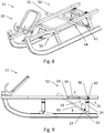
- FIG. 4 shows an inventive slide with automatic safety brake in an isometric view, wherein the flexible seat is not shown.
- FIG. 5 shows the carriage according to the invention according to FIG. 4 in a sectional view, wherein the section in the middle of the carriage and along the direction of travel and the carriage is shown in the unloaded state.
- FIG. 6 shows a detailed view D of the carriage 21 according to the invention according to FIG. 5 .
- FIG. 7 shows the carriage according to the invention according to FIG. 4 in a sectional view, wherein the section in the middle of the carriage and along the direction of travel and the carriage is shown in the loaded state.
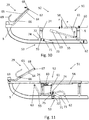
- FIG. 8 shows a preferred, inventive slide with automatic safety brake in an isometric view, wherein the flexible seat is not shown.
- FIG. 9 shows the carriage according to the invention according to FIG. 8 in a sectional view, wherein the section in the middle of the carriage and along the direction of travel and the carriage is shown in the unloaded state.
- FIG. 10 shows the carriage according to the invention according to FIG. 8 in a sectional view, wherein the section in the middle of the carriage and along the direction of travel and the carriage is shown in the loaded state.
- FIG. 11 shows a preferred embodiment of the carriage according to the invention in a sectional view, wherein the section in the middle of the carriage and along the direction of travel and the carriage is shown in the loaded state.
- FIG. 4 discloses a carriage 21 according to the invention in an isometric view, wherein the flexible seat is not shown, comprising two curved runners 22. Further, the slide 21 comprises four feet 24 and two cross braces 25, over the feet 24, the runners 22 and the cross braces 25 are firmly connected.
- the carriage 21 has, in each case above the two skids 22, two spars 26, which are mounted on the transverse struts 25, along the direction of travel.
- the cross struts 25 form with the bars 26, the base for the flexible seat which is formed for example with seat belts.
- the carriage 21 comprises an automatic safety brake 27, a handbrake 28 and a suspension system 29.
- FIG. 5 shows the carriage according to the invention 21 according to FIG. 4 with the automatic safety brake 27, the hand brake 28 and a suspension system 29, wherein the carriage 21 and the automatic safety brake 27 are shown in the unloaded state.
- the automatic safety brake 27 comprises an axis of rotation 30 which is fixedly connected to the rear feet 24, further two angles 31 which form a further axis of rotation 32 and for this purpose are fixedly connected to the rear transverse strut 25.
- the automatic safety brake 27 has two four-bar linkages (cf. FIG. 6 ) are formed on the from a printed sheet 33, two coupling rods 34, two brake claws 35 and the two axes of rotation 30 and 32, wherein the compounds are articulated to each other.
- the automatic safety brake 27 comprises two tension springs 36 which are prestressed in the installed position and act in the connections between coupling rods 34 and brake claws 35 and are connected to the rear feet 24 for this purpose at the opposite end.
- This positioning of the attack point of the tension springs 36 advantageously allows a particularly efficient transmission of the spring force to the joint quadrilateral with a simple construction.
- the use of tension springs 36 as spring elements and coupling rods 34 as coupling offers the advantage of a particularly robust and easy-to-repair construction.
- the kinematic relationships of the automatic safety brake 27 and the tensile forces of the prestressed tension springs 36 cause first a front end 37 of the sheet 33 against gravity acts on a flexible seat and secondly the brake claws 35 lift the rear end of the carriage 21 from the road and through the contact with the roadway produce a braking effect.
- the flexible seat of the carriage 21 according to the invention in FIG. 5 not shown.
- the tension springs 36 can also be connected at another point to the carriage 21 according to the invention, or that they can also be connected at a different location with the four-bar linkage.
- FIG. 6 shows in the detailed view D, the automatic safety brake 27 of the carriage 21 according to the invention according to FIG. 4 , wherein the dashed lines represent rods of the four-bar linkage 38.
- the axis of rotation 30 (point R) and the axis of rotation 32 (point Q) are fixedly connected to the carriage 21 according to the invention and form a frame 39, between the points R and Q, the joint square 38.
- the frame 39 is fixedly connected to the carriage 21.
- the printing sheet 33 is rotatably mounted in the axis of rotation 32 and further articulated at point P with the coupling rods 34.
- the printing sheet 33 forms between the points P and Q a crank 40 of the four-bar linkage 38.
- the coupling rods 34 are pivotally connected at point S with the brake claws 35 and the coupling rods 34 form between the points P and S a coupling 41 of the four-bar linkage 38.
- the brake claws 35 are rotatably mounted in the axis of rotation 30 and form between the points S and R a rocker 42 of the four-bar linkage.
- the prestressed in installation position springs 36 act at point S of the four-bar linkage 38 and press the front end 37 of the sheet 33 against the flexible, not shown seat.
- a lower end 43 of the coupling rod 34 extends beyond the point S of the coupling 41.
- the lower end 43 abuts against the axis of rotation 30 and serves as a travel limit for the tension springs 36.
- This has the advantage that the Path of the front end 37 is limited in the direction of flexible seat and the flexible seat thereby does not have to absorb the entire forces of the tension springs 36.
- About the thus formed four-bar linkage 38 results in angular relationships between the deflection of the Sheet 33 and the deflection of the brake pads 35.
- the four-bar linkage 38 is formed so that a small angular deflection of the sheet 33 results in a larger angular deflection of the brake claws 35, whereby the advantage is obtained that under load of the sheet 33, the brake claws 35 further from lift off the roadway as if the signature is connected to the brake claws via a simple lever.
- the four-bar linkage can be arranged differently on the carriage, for example that the point Q, seen in the direction of travel, can lie behind the rear cross-member, or that the point R, seen in the direction of travel, can be positioned in front of the rear feet .
- the individual rods of the four-bar linkage can be assigned to other parts, for example, that the axes of rotation of the frame with the spars or runners can be firmly connected, and that instead of or with the four-bar linkage other types of coupling gears be installed can.
- FIG. 7 shows the carriage according to the invention 21 according to FIG. 4 , wherein the carriage 21 and the automatic safety brake 27 are shown in the loaded state.
- the load is carried by the driver placed on the flexible seat, this is in FIG. 7 shown as force F schematically.
- the front end 37 of the sheet 33 is moved in the direction of the roadway and further biased by the connection via the coupling rods 34, the tension springs 36 and the brake claws 35 lifted from the road.
- the intervention of the brake claws 35 according to the invention is not contrary to the direction of travel, thereby the advantage is obtained that in mecanicitigen lifting the carriage 21 with the driver, the brake claws 35 do not wedge in the road and thus also act no unwanted loads on the flexible seat.
- the brake claws 35 stand out further from the roadway as a result of the arrangement of the four-bar linkage when the driver sits up, than if the brake claws 35 are connected to the printed sheet 33 via a simple lever.
- FIG. 8 shows a carriage 51 in an isometric view, wherein the flexible seat is not shown.
- the carriage 51 comprises the suspension system 29, an automatic safety brake 52 and a fall brake 53.
- a left hand brake lever 54 and a right hand brake lever 55 are integrated in the automatic safety brake 52, as well as the coupling of the four-bar linkages designed as ropes 61.
- the advantage is obtained that, for example, drive two persons with the carriage 51, the Rear person easier to the handbrake levers 54 and 55 passes as in the previous embodiments. Especially when, for example, an adult (rear person) is traveling with a child (front person) with the carriage 51.
- FIG. 9 shows the carriage 51 according to the invention according to FIG. 8 in a sectional view.
- the automatic safety brake 52 comprises two axes of rotation 56 and 57, the axis of rotation 56 is fixedly connected to the rear cross member 25, and the axis of rotation 57 is fixedly connected to the rear legs 24.
- the straight connection of the two axes of rotation 56 and 57 forms the frame of a four-bar linkage with the points P, Q, R and S.
- the automatic safety brake 52 comprises a pressure sheet 58 with a front end 59 and two leg springs 60.
- the axes of rotation of the leg springs 60th lie in the axis of rotation 56, wherein the leg springs 60 are biased in the installed position and act between the rear cross member 25 and the print sheet 58.
- the use of a leg spring 60 in this installation position advantageously leads to a reduction in the space requirement of the automatic safety brake 52.
- the straight line between the points P and Q of the pressure sheet 58 form the crank of the four-bar linkage.
- the right and left hand brake levers 55 and 54 are rotatably mounted in the axis of rotation 57 and the points S and R of the hand brake levers 54 and 55 form the rocker of the four-bar linkage.
- the automatic safety brake 52 comprises two cables 61 which connect the printed sheet 58 with the handbrake levers 54 and 55. The connection takes place at the points P of the printed sheet 58 and the points S of the hand brake levers 54 and 55.
- the tensioned ropes 61 form the coupling in the four-bar linkage and are flaccid when the automatic safety brake 52 is loaded (cf. FIG. 10 ).
- the hand brake levers 54 and 55 each have a brake claw 62 at the rear end.
- the ropes 61 instead of the coupling rods 34 (see FIGS. 5 to 7 )
- the advantage is obtained that the brake claws 62 of the hand brake levers 54 and 55 are also suitable for the automatic safety brake 52.
- the ropes 61 are stretched with unloaded automatic safety brake 52 and the handbrake levers 54 and 55 are rotated about the axis of rotation 57 so far that the brake claws 62 engage the road and the rear part of the carriage 51 is lifted from this.
- springs or spring mechanisms may be used instead of the illustrated types of springs.
- one type of leaf spring may be integrated in the flexible seating surface.
- coupling rods can be used with slots.
- FIG. 10 shows the carriage 51 according to the invention according to FIG. 8 in the same section as FIG. 9 , wherein the carriage 51 and the automatic safety brake 52 are shown in the loaded state.
- the load is carried by a placed on the flexible seat driver represented by the force F.
- the handbrake levers 54 (see FIG. 8 ) and 55 have two handles 63 at the front end.
- the handbrake levers 54 and 55 are designed so that only by their weight distribution, with free rotation about the axis of rotation 57, the handles 63 sink towards the road.
- the weight of the driver acts on the printed sheet 58 against the prestressed leg springs 60 and rotates the signature 58 in the direction of the road.
- ropes 61 depends only more of a part of the weight of the hand brake lever 54 and 55. This has the advantage that the hand brake lever 54 and 55, with loaded automatic safety brake 52, can be rotated and their brake claws 62 also part of the automatic safety brake 52 are. Furthermore, the coupling by ropes has the advantage that the right and left hand brake levers 54 and 55 are independently operable and thus cornering by the hand brake levers 54 and 55 are introduced.
- handbrake levers can be firmly connected to each other and engage by the operation of a handbrake lever both brake claws in the road and that instead of ropes and other pliable components, such as chains, can be used.
- handbrake for example, may have bowden cables.
- the suspension system 29 comprises a holding frame 64 and a suspension hook 65.
- the support frame 64 is fixedly connected to the two bars 26 and has a rotation axis 66 and a holding handle 67.
- the suspension hook 65 comprises at the upper end a handle 68 and at the lower end two hooks 69.
- About the rotation axis 66 of the hooks 65 is rotatably connected to the support frame 64.
- the driver lets go of the two holding handles 67 and 68 and the hooks 65 folds, by the pulling force of the towing device, about the axis of rotation 66 to the front.
- the suspension hook 65 By folding the suspension hook 65, the bow of the towing device releases and the driver can leave the exit point.
- suspension system in alternative embodiments ropes or closures, which are still easy to open even under heavy load, may have.
- closures are snap shackles from yachting or panic hacking from equitation mentioned.
- a further safety device on the carriage 51 for the uphill drive on the tow bar is the fall brake 53.
- the fall brake 53 comprises a rotation axis 70, a fall brake claw 71 and a stop 72.
- the fall brake claw 71 consists of a lower end 73 and a stop end 74.
- the rotation axis 70 and the stopper 72 are fixedly connected to one of the front feet 24.
- the rotation axis 70 By the rotation axis 70, the fall brake claw 71 is rotatably connected to the carriage 51, wherein the rotation (see arrow) by the stop 72 and the stop end 74 is limited.
- the fall brake claw 71 and its mounting in the axis of rotation 70 are designed so that while driving the lower end 73, without noticeable braking effect, permanently touches the road.
- FIG. 11 shows the carriage 51 according to the invention in a preferred embodiment, wherein the printing sheet 58, starting from the leg spring 60 counter to the direction of travel of the carriage 51 extends.
- the leg spring is attached to one of the feet 24.
- the advantage is achieved that the leg spring 60 is arranged protected from shocks.
- Particularly preferred is the arrangement of the leg spring in the direction of travel behind one of the front feet 24, since at this position a particularly good protection against mechanical damage is achieved.
- the fall brake claw 71 and the brake claw 62 are mounted on the carriage 51 such that they can pivot about a common axis of rotation 75. This gives us the advantage that the entire carriage 51 is constructed more compactly and with a smaller number of components.
Landscapes
- Engineering & Computer Science (AREA)
- Chemical & Material Sciences (AREA)
- Combustion & Propulsion (AREA)
- Transportation (AREA)
- Mechanical Engineering (AREA)
- Braking Arrangements (AREA)
Abstract
Schlitten (21, 51), welcher zwei Kufen (22), zwei Holme (26), zwei Querstreben (25), vier Füße (24), sowie eine flexible Sitzfläche und eine automatische Sicherheitsbremse aufweist, welche zumindest ein Gelenksviereck (38), welches einen Druckbogen (33, 58), eine Bremskralle (35, 62), eine Koppel (41) sowie ein Federelement (36, 60) beinhaltet, aufweist, wobei die Bremskralle und der Druckbogen schwenkbar am Schlitten gelagert sind und die Koppel mit dem Druckbogen und der Bremskralle gelenkig verbunden ist, wobei das Federelement mit dem Schlitten verbunden ist und eine Kraft auf das Gelenksviereck ausübt, wobei im unbelasteten Zustand des Schlittens der Druckbogen im Wesentlichen durch die Holmebene anliegend an die flexible Sitzfläche verschwenkt, sowie die Bremskralle zum Bremsen zwangsgeführt durch die Kufenebene nach unten verschwenkt ist, und im durch den sitzenden Benutzer belasteten Zustand des Schlittens sich der an die flexible Sitzfläche anliegende Druckbogen sowie die Bremskralle im Wesentlichen zwischen der Holmebene und der Kufenebene befinden und den Schlitten somit nicht bremst.Carriage (21, 51) having two runners (22), two spars (26), two cross struts (25), four feet (24), and a flexible seat and an automatic safety brake, which at least one joint square (38), which comprises a printing sheet (33, 58), a brake claw (35, 62), a coupling (41) and a spring element (36, 60), wherein the brake claw and the printing sheet are pivotally mounted on the carriage and the coupling with the Sheet and the brake claw is hingedly connected, wherein the spring element is connected to the carriage and exerts a force on the joint quadrilateral, pivoted in the unloaded state of the carriage of the sheet substantially by the spar plane adjacent to the flexible seat, and forcibly guided brake claw for braking is pivoted downwards through the skid plane, and in the loaded by the seated user state of the carriage, the pressure applied to the flexible seat sheet and d The brake claw are located substantially between the spar plane and the skid plane and thus does not brake the carriage.
Description
Die Erfindung betrifft einen Schlitten gemäß dem Oberbegriff des Anspruchs 1.
-
Figur 1handelsüblichen Schlitten 1 in einer Draufsicht, ohne montierter flexibler Sitzfläche, umfassend zweigebogene Kufen 2. Des Weiteren umfasst derSchlitten 1 vierFüße 3 und zwei Querstreben 4, wobei über dieFüße 3, dieKufen 2 und die Querstreben 4 fest miteinander verbunden sind. DerSchlitten 1 weist, jeweils oberhalb der beidenKufen 2, zweiHolme 5 auf, die auf den Querstreben 4, entlang der Fahrtrichtung, montiert sind. Die Querstreben 4 bilden mit denHolmen 5 die Basis für die flexible Sitzfläche die zum Beispiel mit Sitzgurten gebildet ist. DerSchlitten 1 umfasst eineHandbremse 6 die aus einerDrehachse 7, einem Handbremshebel 8 besteht und eineautomatische Sicherheitsbremse 9, die am unteren Ende zwei Bremskrallen und am oberen Ende einenDruckbogen 10 aufweist und wobei dieDrehachse 7 auch Teil derautomatischen Sicherheitsbremse 9 ist. Der Handbremshebel 8 weist am vorderen Ende einenHaltegriff 11 und am gegenüberliegenden Ende zweiHandbremskrallen 12 auf. DerSchlitten 1 umfasst zwei Lagerböcke, die dieDrehachse 7 aufnehmen in welcher dieHandbremse 6 und dieautomatische Sicherheitsbremse 9 drehbar gelagert sind. Dieautomatische Sicherheitsbremse 9 umfasst eine Zugfeder, die mit dem in Fahrtrichtung gesehen vorderen der Querstreben 4 verbunden ist. -
Figur 2Schlitten 1 gemäßFigur 1Bremskrallen 14 derautomatische Sicherheitsbremse 9 durch dievorgespannte Zugfeder 13 in eine Fahrbahn eingreifen und dieHandbremskrallen 12 derHandbremse 6 nicht in die Fahrbahn eingreifen. Die zweiLagerböcke 15 sind durch Verbindungsmittel mit denKufen 2 fest verbunden. -
Figur 3Schlitten 1 gemäßFigur 1Druckbogen 10 derautomatischen Sicherheitsbremse 9 wirkt und eine Kraft FH auf denHaltegriff 11 derHandbremse 6 wirkt. Die Kraft F ist zum Bespiel durch einen, auf der Sitzfläche positionierten, Fahrer eingeleitet der auch die Kraft FH durch ziehen desHaltgriffs 11 aufbringt. Die Kraft F wirkt gegen dievorgespannte Zugfeder 13 und hebt, durch Drehung derautomatischen Sicherheitsbremse 9 um dieDrehachse 7, dieBremskrallen 14 aus der Fahrbahn. Die Kraft FH bewirkt eine Drehung derHandbremse 6 um dieDrehachse 7 wodurch dieHandbremskrallen 12 in die Fahrbahn eingreifen.
-
FIG. 1 discloses a commerciallyavailable carriage 1 in a plan view, without mounted flexible seat, comprising twocurved skids 2. Furthermore, thecarriage 1 comprises fourfeet 3 and two cross struts 4, wherein connected via thefeet 3, therunners 2 and the cross braces 4 firmly together are. Thecarriage 1 has, in each case above the twoskids 2, twospars 5, which are mounted on the transverse struts 4, along the direction of travel. The cross struts 4 form with thebars 5, the basis for the flexible seat which is formed for example with seat belts. Thecarriage 1 comprises ahandbrake 6 which consists of an axis ofrotation 7, a handbrake lever 8 and anautomatic safety brake 9, which has two brake claws at the lower end and a printedsheet 10 at the upper end and wherein the axis ofrotation 7 is also part of theautomatic safety brake 9. The hand brake lever 8 has at the front end ahandle 11 and at the opposite end twohand brake claws 12. Thecarriage 1 comprises two bearing blocks which receive the axis ofrotation 7 in which thehandbrake 6 and theautomatic safety brake 9 are rotatably mounted. Theautomatic safety brake 9 comprises a tension spring which is connected to the front of the transverse struts 4 as seen in the direction of travel. -
FIG. 2 shows thecarriage 1 according toFIG. 1 in a sectional view AA, wherein thebrake claws 14 engage theautomatic safety brake 9 by theprestressed tension spring 13 in a roadway and thehand brake claws 12 of thehand brake 6 do not engage in the roadway. The two bearingblocks 15 are fixedly connected by connecting means with therunners 2. -
FIG. 3 shows thecarriage 1 according toFIG. 1 in a sectional view BB, wherein a force F acts on the printedsheet 10 of theautomatic safety brake 9 and a force F H acts on thehandle 11 of theparking brake 6. The force F is introduced for example by a, positioned on the seat, driver of the force F H by pulling theholding handle 11 applies. The force F acts against theprestressed tension spring 13 and lifts, by rotation of theautomatic safety brake 9 about the axis ofrotation 7, thebrake pads 14 from the road. The force F H causes a rotation of thehand brake 6 about therotation axis 7 whereby thehand brake claws 12 engage in the roadway.
Der in den
Beim gezeigten Ausführungsbeispiel hat es sich als Nachteil erwiesen, dass die gezeigte Ausführung der automatischen Sicherheitsbremse unweigerlich, während einer Fahrt in die Fahrbahn eingreift. Besonders bei Fahrten mit hoher Geschwindigkeit und auf unebenen Fahrbahnen, kann der Schlitten mitsamt dem Fahrer von der Fahrbahn abheben wodurch kurzzeitig keine Kraft auf den Druckbogen wirkt und die Bremskrallen der automatischen Sicherheitsbremse in die Fahrbahn eingreifen. Verstärkt wird diese Wirkung dadurch, dass die gezeigten Bremskrallen entgegen der Fahrtrichtung eingreifen und deren Bremskräfte hohe Kräfte des Druckbogens gegen die Sitzfläche verursachen und die Sitzfläche beschädigen können. Insbesondere wenn der Schlitten häufig, zum Beispiel als Verleihgerät, im Einsatz ist.The in the
In the embodiment shown, it has proven to be a disadvantage that the embodiment shown, the automatic safety brake inevitably engages while driving in the roadway. Especially when driving at high speed and on uneven roads, the carriage can lift off the road together with the driver which briefly acts no force on the sheet and engage the brake claws of the automatic safety brake in the road. This effect is reinforced by the fact that the brake claws shown counter to the direction of travel and their braking forces cause high forces of the sheet against the seat and can damage the seat. In particular, when the carriage is often, for example, as rental equipment, in use.
Bei einer Fahrt mit dem gezeigten Ausführungsbeispiel kann die automatische Sicherheitsbremse ungewollt aber permanent in die Fahrbahn eingreifen und leicht bremsen. Besonders auf einer Fahrbahn, welche frisch präpariert ist, sinken die Kufen des Schlittens tiefer in den Schnee und infolgedessen kommen die Bremskrallen der automatischen Sicherheitsbremse mit der Fahrbahn permanent in Berührung. Es hat sich als Nachteil erwiesen, dass über den direkten Hebel zwischen Bremskrallen und Druckbogen der automatischen Sicherheitsbremse die Bremskrallen unzureichend von der Fahrbahn gehoben werden, insbesondere wenn der vertikale Weg des Druckbogens durch die konstruktiven Gegebenheiten eines handelsüblichen Schlittens beschränkt ist.When driving with the illustrated embodiment, the automatic safety brake can unintentionally but permanently intervene in the road and brake easily. Especially on a road surface, which is freshly prepared, the skids of the carriage sink deeper into the snow and as a result, come the brake claws of the automatic safety brake with the road permanently in touch. It has proven to be a disadvantage that the brake claws are insufficiently lifted off the roadway via the direct lever between the brake claws and the printing sheet of the automatic safety brake, in particular if the vertical path of the printed sheet is limited by the structural conditions of a commercially available carriage.
Es hat sich als Nachteil erwiesen, dass der zusätzliche Aufbau der Handbremse und der automatischen Sicherheitsbremse durch das zusätzliche Gewicht den Schlitten, besonders für Kinder, unhandlicher macht.It has proven to be a disadvantage that the additional construction of the handbrake and the automatic safety brake by the additional weight makes the slide, especially for children, more cumbersome.
Der Erfindung liegt die Aufgabe zu Grunde, einen Schlitten mit einer automatischen Sicherheitsbremse zu schaffen mit dem vorgenannte Nachteile überwunden werden können.The invention is based on the object to provide a slide with an automatic safety brake with the aforementioned disadvantages can be overcome.
Erfindungsgemäß wird diese Aufgabenstellung dadurch gelöst, dass die automatische Sicherheitsbremse zumindest ein Gelenksviereck, welches einen Druckbogen, eine Bremskralle, eine Koppel sowie ein Federelement beinhaltet, aufweist, wobei die Bremskralle und der Druckbogen schwenkbar am Schlitten gelagert sind und die Koppel mit dem Druckbogen und der Bremskralle gelenkig verbunden ist, wobei das Federelement mit dem Schlitten verbunden ist und eine Kraft auf das Gelenksviereck ausübt, wobei im unbelasteten Zustand des Schlittens der Druckbogen im Wesentlichen durch die Holmebene anliegend an die flexible Sitzfläche verschwenkt, sowie die Bremskralle zwangsgeführt durch die Kufenebene verschwenkt ist, und im belasteten Zustand des Schlittens sich der an die flexible Sitzfläche anliegende Druckbogen sowie die Bremskralle im Wesentlichen zwischen der Holmebene und der Kufenebene befinden.According to the invention, this object is achieved in that the automatic safety brake at least one joint quadrangle, which includes a sheet, a brake claw, a coupling and a spring element comprises, wherein the brake claw and the sheet are pivotally mounted on the carriage and the coupling with the sheet and the Brake claw is hingedly connected, wherein the spring element is connected to the carriage and exerts a force on the joint quadrilateral, pivoted in the unloaded state of the carriage of the sheet substantially by the spar plane adjacent to the flexible seat, and the brake claw is forcibly guided by the skid plane pivoted , And in the loaded state of the carriage, the sheet resting against the flexible seat sheet and the brake claw are located substantially between the spar plane and the skid plane.
Ein Gelenkviereck bzw. ein viergliedriges Koppelgetriebe besteht aus vier in einer Ebene liegenden drehbar verbundenen Stäben. Die vier Stäbe unterscheiden sich in ihrer Aufgabe und werden Gestell, Schwinge, Koppel und Kurbel genannt. In der Kinematik wird das Gestell als ortsfest angesehen (festgehalten) und die Kurbel wird angetrieben. Die Koppel überträgt die Bewegung der Kurbel auf die Schwinge. Durch festlegen der geometrischen Bedingungen des Gelenksvierecks sind die Bewegungsabläufe der einzelnen Stäbe vordefiniert und infolgedessen auch die Winkelausschläge der bewegten Stäbe definiert. Je nach geometrischer Vorauslegung kann somit ein geringer Winkelausschlag der Kurbel eine größeren Winkelausschlag der Schwinge bedeuten oder umgekehrt, daher auch der Name viergliedriges Koppelgetriebe.A four-bar linkage or a four-link coupling gear consists of four in a plane rotatably connected rods. The four bars differ in their task and are called frame, swingarm, paddock and crank. In the kinematics, the frame is considered stationary (held) and the crank is driven. The coupling transmits the movement of the crank to the rocker. By defining the geometric conditions of the four-bar linkage, the movements of the individual bars are predefined and, as a result, the angular deflections of the moving bars are also defined. Depending on the geometric design, a small angular deflection of the crank can thus mean a greater angular deflection of the rocker or vice versa, hence the name four-link coupling mechanism.
Weitere vorteilhafte Ausgestaltungen des erfindungsgemäßen Schlittens mit automatischer Sicherheitsbremse werden im Folgenden anhand der Figuren näher erläutert.Further advantageous embodiments of the carriage according to the invention with automatic safety brake are explained in more detail below with reference to FIGS.
Eine nähere Beschreibung der Gelenkvierecke folgt in
Es kann erwähnt werden, dass die Zugfedern 36 auch an einer anderen Stelle mit dem erfindungsgemäßen Schlitten 21 verbunden sein können, beziehungsweise dass diese auch an einer andere Stelle mit dem Gelenkviereck verbunden sein können.A closer description of the four-bar linkages follows in
It can be mentioned that the tension springs 36 can also be connected at another point to the
Es kann erwähnt werden, dass das Gelenkviereck am Schlitten anders angeordnet werden kann, zum Beispiel das der Punkt Q, in Fahrtrichtung gesehen, hinter der hinteren Querstrebe liegen kann, oder dass der Punkt R, in Fahrtrichtung gesehen, vor den hinteren Füßen positioniert werden kann. Des Weiteren sei erwähnt, dass die einzelnen Stäbe des Gelenkvierecks anderen Teilen zugeordnet sein können, zum Beispiel dass die Drehachsen des Gestells mit den Holmen oder mit den Kufen fest verbunden sein können, und dass anstatt oder mit dem Gelenkviereck auch andere Arten von Koppelgetrieben verbaut sein können.It may be mentioned that the four-bar linkage can be arranged differently on the carriage, for example that the point Q, seen in the direction of travel, can lie behind the rear cross-member, or that the point R, seen in the direction of travel, can be positioned in front of the rear feet , Furthermore, it should be mentioned that the individual rods of the four-bar linkage can be assigned to other parts, for example, that the axes of rotation of the frame with the spars or runners can be firmly connected, and that instead of or with the four-bar linkage other types of coupling gears be installed can.
Es kann erwähnt werden, dass anstatt der gezeigten Federarten andere Federarten oder Federmechanismen verwendet werden können. Zum Beispiel kann eine Art Blattfeder in der flexiblen Sitzfläche integriert sein. Des Weiteren kann erwähnt werden, dass anstatt der Seile auch Koppelstangen mit Langlöchern verwendet werden können.It may be mentioned that other types of springs or spring mechanisms may be used instead of the illustrated types of springs. For example, one type of leaf spring may be integrated in the flexible seating surface. Furthermore, it can be mentioned that instead of the ropes also coupling rods can be used with slots.
Es sei erwähnt, dass die Handbremshebel miteinander fest verbunden sein können und durch die Betätigung eines Handbremshebels beide Bremskrallen in die Fahrbahn eingreifen und dass anstatt der Seile auch andere biegeschlaffe Komponenten, wie zum Beispiel Ketten, verwendet werden können. Des Weiteren sei erwähnt, dass die Handbremse zum Beispiel Bowdenzüge aufweisen kann.
It should be noted that the handbrake levers can be firmly connected to each other and engage by the operation of a handbrake lever both brake claws in the road and that instead of ropes and other pliable components, such as chains, can be used. Furthermore, it should be mentioned that the handbrake, for example, may have bowden cables.
Das Einhängesystem 29 umfasst einen Halterahmen 64 und einen Einhängehaken 65. Der Halterahmen 64 ist mit den beiden Holmen 26 fest verbunden und weist eine Drehachse 66 und einen Haltgriff 67 auf. Der Einhängehaken 65 umfasst am oberen Ende einen Haltegriff 68 und am unteren Ende zwei Haken 69. Über die Drehachse 66 ist der Einhängehaken 65 drehbar mit dem Halterahmen 64 verbunden. Mit dem dargestellten Einhängesystem 29 ist eine sichere Bergauffahrt am Schlepp- oder Tellerlift gewährleistet. Am Einstieg des Schlepplifts umfasst der Fahrer mit den Händen die Haltegriffe 67 und 68, anschließend wird der Bügel der Schleppvorrichtung in die beiden Haken 69 eingehängt und der Fahrer mit dem Schlitten 51 hochgezogen. Am Ausstieg des Schlepplifts lässt der Fahrer die beiden Haltgriffe 67 und 68 los und der Einhängehaken 65 klappt, durch die Zugkraft der Schleppvorrichtung, um die Drehachse 66 nach vorne. Durch das Vorklappen des Einhängehakens 65 löst sich der Bügel der Schleppvorrichtung und der Fahrer kann die Ausstiegstelle verlassen.The
Es sei erwähnt, dass das Einhängesystem in alternativen Ausführungsvarianten Seile oder Verschlüsse, die auch unter großer Last noch leicht zu öffnen sind, aufweisen kann. Als Beispiele für derartige Verschlüsse seien Schnappschäkel aus dem Segelsport oder Panikhacken aus dem Reitsport erwähnt.It should be noted that the suspension system in alternative embodiments ropes or closures, which are still easy to open even under heavy load, may have. As examples of such closures are snap shackles from yachting or panic hacking from equitation mentioned.
Eine weitere Sicherheitseinrichtung am Schlitten 51 für die Bergauffahrt am Schlepplift ist die Fallbremse 53. Die Fallbremse 53 umfasst eine Drehachse 70, eine Fallbremskralle 71 und einen Anschlag 72. Die Fallbremskralle 71 besteht aus einem unteren Ende 73 und einem Anschlagsende 74. Die Drehachse 70 und der Anschlag 72 sind fest mit einem der vorderen Füße 24 verbunden. Durch die Drehachse 70 ist die Fallbremskralle 71 drehbar mit dem Schlitten 51 verbunden, wobei die Drehung (siehe Pfeil) durch den Anschlag 72 und das Anschlagsende 74 begrenzt ist. Die Fallbremskralle 71 und deren Lagerung in Drehachse 70 sind so ausgeführt, dass während der Fahrt das untere Ende 73, ohne bemerkbare Bremswirkung, permanent die Fahrbahn berührt. Löst sich während der Bergauffahrt am Schlepplift ungewollt der Bügel, oder bricht das Schleppseil, kommt es zu einer kurzen Rückwärtsfahrt und die Fallbremskralle 71 verkeilt sich in der Fahrbahn und verdreht sich bis das Anschlagsende 74 den Anschlag 72 berührt. Der Schlitten 51 kommt mit dem Fahrer zum Stillstand und kann sicher die Schlepptrasse verlassen. Die Fallbremse 53 verhindert ein ungewolltes Rückwärtsfahren des Schlittens 51.A further safety device on the
Claims (13)
die automatische Sicherheitsbremse (27, 52) zumindest ein Gelenksviereck (38), welches zumindest einen Druckbogen (33, 58) zumindest eine Bremskralle (35, 62), zumindest eine Koppel (41) sowie zumindest ein Federelement beinhaltet, aufweist, wobei die Bremskralle (35, 62) und der Druckbogen (33, 58) schwenkbar am Schlitten (21, 51) gelagert sind und die Koppel (41) mit dem Druckbogen (33, 58) und der Bremskralle (35, 62) gelenkig verbunden ist, wobei das Federelement mit dem Schlitten (21, 51) verbunden ist und eine Kraft auf das Gelenksviereck (38) ausübt, wobei im unbelasteten Zustand des Schlittens (21, 51) der Druckbogen (33, 58) im Wesentlichen durch die Holmebene anliegend an die flexible Sitzfläche verschwenkt, sowie die Bremskralle (35, 62) zwangsgeführt durch die Kufenebene verschwenkt ist, und im belasteten Zustand des Schlittens (21, 51) sich der an die flexible Sitzfläche anliegende Druckbogen (33, 58) sowie die Bremskralle (35, 62) im Wesentlichen zwischen der Holmebene und der Kufenebene befinden.Carriage (21, 51), which has two skids (22), two spars (26), two cross struts (25), four feet (24), and a flexible seat, wherein the runners (22) arranged in a skid plane parallel zueinender are, and the spars (26) are arranged parallel to each other in a plane parallel to the plane of the ladder plane, between the spars (26) is the flexible seat, and wherein each runner (22) by means of at least two feet (24) with a spar ( 26) is connected, and the spars (26) by means of the transverse struts (25) are connected, wherein the carriage (21, 51) comprises an automatic safety brake (27, 52), characterized in that
the automatic safety brake (27, 52) has at least one articulated quadrilateral (38) which contains at least one printed sheet (33, 58) at least one brake claw (35, 62), at least one coupling (41) and at least one spring element, wherein the brake claw (35, 62) and the printing sheet (33, 58) are pivotally mounted on the carriage (21, 51) and the coupling (41) with the pressure sheet (33, 58) and the brake claw (35, 62) is hingedly connected, wherein the spring element is connected to the carriage (21, 51) and exerts a force on the articulated quadrilateral (38), wherein in the unloaded state of the carriage (21, 51) the signature (33, 58) substantially abuts the flexible plane through the spar plane Seat pivoted, and the brake claw (35, 62) forcibly guided by the skid plane is pivoted, and in the loaded state of the carriage (21, 51) is applied to the flexible seat pressure sheet (33, 58) and the brake claw (35, 62) essentially between the Holmeben e and the business level.
Applications Claiming Priority (1)
| Application Number | Priority Date | Filing Date | Title |
|---|---|---|---|
| ATA8003/2017A AT518776B1 (en) | 2016-08-31 | 2016-08-31 | Carriage with automatic safety brake |
Publications (1)
| Publication Number | Publication Date |
|---|---|
| EP3290291A1 true EP3290291A1 (en) | 2018-03-07 |
Family
ID=59655954
Family Applications (1)
| Application Number | Title | Priority Date | Filing Date |
|---|---|---|---|
| EP17186819.3A Withdrawn EP3290291A1 (en) | 2016-08-31 | 2017-08-18 | Sledge with automatic safety brake |
Country Status (2)
| Country | Link |
|---|---|
| EP (1) | EP3290291A1 (en) |
| AT (1) | AT518776B1 (en) |
Cited By (5)
| Publication number | Priority date | Publication date | Assignee | Title |
|---|---|---|---|---|
| EP3459818A1 (en) * | 2017-03-07 | 2019-03-27 | Reinhard Ferner | Hand brake for sleds |
| AT521656A1 (en) * | 2018-02-16 | 2020-03-15 | Ferner Reinhard | Sledge with a hanging device |
| CN114670916A (en) * | 2022-02-11 | 2022-06-28 | 中国第一汽车股份有限公司 | Double sled's arresting gear and sled car |
| AT525542B1 (en) * | 2022-09-01 | 2023-05-15 | Hettegger Erich | Slide with braking and steering function |
| AT525712A3 (en) * | 2023-03-30 | 2023-11-15 | Ferner Reinhard | Vehicle for movement in one direction of travel with a hook element |
Citations (4)
| Publication number | Priority date | Publication date | Assignee | Title |
|---|---|---|---|---|
| DE222764C (en) * | 1960-08-13 | 1910-06-04 | Hardt Amalie Adalbert | BRAKE FOR TOBOGGAN SLEDGING WITH A SPRING BRAKE ARM |
| AT6947U2 (en) * | 2004-03-01 | 2004-06-25 | Susanne Koefler | BOB |
| DE202005005141U1 (en) * | 2005-03-31 | 2005-05-25 | Gruber, Rupert | Sledge with seat and runners, has braking system operated by bar linked to braking component on each runner, providing simultaneous operation of both brakes |
| EP2210648A1 (en) * | 2007-09-19 | 2010-07-28 | Junzo Ota | Play apparatus and elastic mechanism |
Family Cites Families (2)
| Publication number | Priority date | Publication date | Assignee | Title |
|---|---|---|---|---|
| US410466A (en) * | 1889-09-03 | Sled-brake | ||
| DE811428C (en) * | 1950-01-10 | 1951-08-20 | Franz Gerhold | Toboggan and transport sledge |
-
2016
- 2016-08-31 AT ATA8003/2017A patent/AT518776B1/en active
-
2017
- 2017-08-18 EP EP17186819.3A patent/EP3290291A1/en not_active Withdrawn
Patent Citations (4)
| Publication number | Priority date | Publication date | Assignee | Title |
|---|---|---|---|---|
| DE222764C (en) * | 1960-08-13 | 1910-06-04 | Hardt Amalie Adalbert | BRAKE FOR TOBOGGAN SLEDGING WITH A SPRING BRAKE ARM |
| AT6947U2 (en) * | 2004-03-01 | 2004-06-25 | Susanne Koefler | BOB |
| DE202005005141U1 (en) * | 2005-03-31 | 2005-05-25 | Gruber, Rupert | Sledge with seat and runners, has braking system operated by bar linked to braking component on each runner, providing simultaneous operation of both brakes |
| EP2210648A1 (en) * | 2007-09-19 | 2010-07-28 | Junzo Ota | Play apparatus and elastic mechanism |
Cited By (10)
| Publication number | Priority date | Publication date | Assignee | Title |
|---|---|---|---|---|
| EP3459818A1 (en) * | 2017-03-07 | 2019-03-27 | Reinhard Ferner | Hand brake for sleds |
| AT521656A1 (en) * | 2018-02-16 | 2020-03-15 | Ferner Reinhard | Sledge with a hanging device |
| AT521656B1 (en) * | 2018-02-16 | 2020-07-15 | Ferner Reinhard | Sledge with a hanging device |
| CN114670916A (en) * | 2022-02-11 | 2022-06-28 | 中国第一汽车股份有限公司 | Double sled's arresting gear and sled car |
| CN114670916B (en) * | 2022-02-11 | 2023-09-12 | 中国第一汽车股份有限公司 | Braking device of double sledge and sledge |
| AT525542B1 (en) * | 2022-09-01 | 2023-05-15 | Hettegger Erich | Slide with braking and steering function |
| AT525542A4 (en) * | 2022-09-01 | 2023-05-15 | Hettegger Erich | Slide with braking and steering function |
| WO2024044800A1 (en) | 2022-09-01 | 2024-03-07 | Georg Winkler | Toboggan with braking and steering function |
| AT525712A3 (en) * | 2023-03-30 | 2023-11-15 | Ferner Reinhard | Vehicle for movement in one direction of travel with a hook element |
| AT525712B1 (en) * | 2023-03-30 | 2024-03-15 | Ferner Reinhard | Vehicle for movement in one direction of travel with a hook element |
Also Published As
| Publication number | Publication date |
|---|---|
| AT518776B1 (en) | 2018-01-15 |
| AT518776A4 (en) | 2018-01-15 |
Similar Documents
| Publication | Publication Date | Title |
|---|---|---|
| EP3290291A1 (en) | Sledge with automatic safety brake | |
| EP1590224B1 (en) | Hand-moveable transport trolley | |
| WO2007042193A1 (en) | Luggage trolley | |
| DE187291C (en) | ||
| DE102011010909A1 (en) | Two-or three wheeled sideways inclinable vehicle, particularly motor vehicle, has leg support, which is movably attached against vehicle frame, where supporting stand is guided towards ground by movement of leg support | |
| DE2506955C3 (en) | Stop and lock device | |
| DE3405360C2 (en) | Conveyor trolleys of a drag chain conveyor system that can be moved on a mounting rail | |
| DE2526905C3 (en) | Trolley for a drag chain conveyor system | |
| DE564374C (en) | Device for automatically transferring part of the trailer weight to the towing vehicle | |
| DE1051133B (en) | Device to facilitate the coupling of a single-axle trailer provided with a drawbar | |
| DE516215C (en) | Drawbar for pallet truck | |
| DE1269951B (en) | Loading bridge | |
| DE504894C (en) | Automatic trailer coupling in connection with an automatic trailer brake for motor vehicles | |
| DE877991C (en) | Accident protection device for prams and sports cars | |
| DE544067C (en) | Lift truck with swing arms | |
| DE682994C (en) | Pallet truck | |
| DE494052C (en) | Coupling between the towing vehicle and the trailer with an automatic device for loading the towing vehicle with part of the weight of the trailer | |
| DE53921C (en) | Device for quick unhitching of the draft animals and immediate braking of the wagons | |
| DE2111140B2 (en) | FOLDABLE LADDER | |
| DE4484C (en) | Automatic brake for railway vehicles | |
| DE102015000163A1 (en) | Retractable support device for a single-track vehicle | |
| DE465070C (en) | Vehicle with charger | |
| DE146111C (en) | ||
| DE185153C (en) | ||
| DE429435C (en) | Lifting trolleys |
Legal Events
| Date | Code | Title | Description |
|---|---|---|---|
| PUAI | Public reference made under article 153(3) epc to a published international application that has entered the european phase |
Free format text: ORIGINAL CODE: 0009012 |
|
| STAA | Information on the status of an ep patent application or granted ep patent |
Free format text: STATUS: THE APPLICATION HAS BEEN PUBLISHED |
|
| AK | Designated contracting states |
Kind code of ref document: A1 Designated state(s): AL AT BE BG CH CY CZ DE DK EE ES FI FR GB GR HR HU IE IS IT LI LT LU LV MC MK MT NL NO PL PT RO RS SE SI SK SM TR |
|
| AX | Request for extension of the european patent |
Extension state: BA ME |
|
| STAA | Information on the status of an ep patent application or granted ep patent |
Free format text: STATUS: THE APPLICATION IS DEEMED TO BE WITHDRAWN |
|
| 18D | Application deemed to be withdrawn |
Effective date: 20180908 |