EP3289849A1 - Schleppschlauchanordnung für landwirtschaftlche verteilmaschinen zur ausbringung von flüssigkeiten - Google Patents
Schleppschlauchanordnung für landwirtschaftlche verteilmaschinen zur ausbringung von flüssigkeiten Download PDFInfo
- Publication number
- EP3289849A1 EP3289849A1 EP17401097.5A EP17401097A EP3289849A1 EP 3289849 A1 EP3289849 A1 EP 3289849A1 EP 17401097 A EP17401097 A EP 17401097A EP 3289849 A1 EP3289849 A1 EP 3289849A1
- Authority
- EP
- European Patent Office
- Prior art keywords
- hose
- hoses
- articulated joint
- joint
- towing
- Prior art date
- Legal status (The legal status is an assumption and is not a legal conclusion. Google has not performed a legal analysis and makes no representation as to the accuracy of the status listed.)
- Granted
Links
Images

Classifications
-
- A—HUMAN NECESSITIES
- A01—AGRICULTURE; FORESTRY; ANIMAL HUSBANDRY; HUNTING; TRAPPING; FISHING
- A01C—PLANTING; SOWING; FERTILISING
- A01C23/00—Distributing devices specially adapted for liquid manure or other fertilising liquid, including ammonia, e.g. transport tanks or sprinkling wagons
- A01C23/001—Sludge spreaders, e.g. liquid manure spreaders
-
- A—HUMAN NECESSITIES
- A01—AGRICULTURE; FORESTRY; ANIMAL HUSBANDRY; HUNTING; TRAPPING; FISHING
- A01M—CATCHING, TRAPPING OR SCARING OF ANIMALS; APPARATUS FOR THE DESTRUCTION OF NOXIOUS ANIMALS OR NOXIOUS PLANTS
- A01M7/00—Special adaptations or arrangements of liquid-spraying apparatus for purposes covered by this subclass
- A01M7/005—Special arrangements or adaptations of the spraying or distributing parts, e.g. adaptations or mounting of the spray booms, mounting of the nozzles, protection shields
- A01M7/006—Mounting of the nozzles
-
- A—HUMAN NECESSITIES
- A01—AGRICULTURE; FORESTRY; ANIMAL HUSBANDRY; HUNTING; TRAPPING; FISHING
- A01M—CATCHING, TRAPPING OR SCARING OF ANIMALS; APPARATUS FOR THE DESTRUCTION OF NOXIOUS ANIMALS OR NOXIOUS PLANTS
- A01M7/00—Special adaptations or arrangements of liquid-spraying apparatus for purposes covered by this subclass
- A01M7/005—Special arrangements or adaptations of the spraying or distributing parts, e.g. adaptations or mounting of the spray booms, mounting of the nozzles, protection shields
- A01M7/0071—Construction of the spray booms
- A01M7/0075—Construction of the spray booms including folding means
Definitions
- the invention relates to a drag hose arrangement for agricultural distribution machines for the application of liquids according to the preamble of claim 1.
- the invention is based on the object to allow in a simple manner for the transport position closer approach of the tow hoses to the upright support beams to reduce the transport width of the machine.
- an articulated joint is arranged in the towing hose, that the respective hinge axis of the articulated joint points in the deployment position of the distributor bar in the direction of travel.
- the articulated joint is at least approximately in the immediate vicinity of the underside of the distributor bar.
- the respective trailing hose can bend down over the articulated joint in the immediate vicinity of the distributor bar in its upright transport position, so that the trailing hose is in the immediate vicinity of the upright distributor bar.
- a simple embodiment for the knee joint can be achieved in that the respective articulated joint consists of two articulated parts which are pivotably connected to one another by means of a joint and are provided with tube-like recesses in the longitudinal direction of the trailing tubes.
- the easily flexible hose piece may be formed as a corrugated pipe, corrugated hose or silicone hose.
- the respective drag hose can be pivoted by means of the articulated joint from its application position at least approximately 90 ° into its transport position.
- the close approach of the tow hoses is achieved on the upright distribution bar in transport position.
- a simple embodiment and integration of the articulated joint in the respective towing hose can be achieved in that the connecting device is arranged on one joint part of the kick joint and on the other joint part a hose nozzle for arranging the trailing hose.
- a simple attachment of the trailing hoses to the liquid outlets of the supply line is achieved in that the connecting device is designed like a bayonet.
- the spray boom formed as a distributor bar 1 is shown in the application position of a agricultural distribution machine designed as a plant protection sprayer.
- the distributor bar 1 is arranged by means of a suspension device 2 in a known manner pivotable and height adjustable on a arranged on the frame, not shown, a crop protection sprayer intermediate frame 3.
- a crop protection sprayer intermediate frame 3 In the Fig.1 only the right part of the distributor bar 1 is shown.
- the manifold 1 consists of several interconnected by means of hinged joints 4 sections 5.
- the manifold 1 can from the in FIG. 1 represented transverse to the direction of travel in a horizontal orientation extending application position in the Figure 5 , in turn, only the right part of the distribution bar 1 is shown, folded upright transport position can be spent.
- a supply line 6 to be charged with liquid is arranged in a known manner.
- This supply line 6 are supplied in a known and therefore not shown manner, the dispensed liquids in metered form.
- the supply line 6 has at uniform intervals to each other arranged connection couplings 7 with liquid outlets.
- Towing hoses 9 of a trailing hose arrangement 10 are respectively to be fastened to the connection coupling 7 of the liquid outlets via connecting devices 8.
- the connection coupling 4 and the connecting device 8 are formed like a bayonet.
- a few drag hoses 9 are arranged on the connection couplings 7 of the distributor bar 1, which have the liquid outlets.
- 1 drag hoses 9 are arranged for the discharge of liquids via tow hoses 9 at all liquid outlets having connection couplings 7 of the manifold.
- the tow hoses 9 depend in the discharge position of the spray boom 1 of the connection coupling 7 at least approximately vertically downwards.
- an articulated joint 11 is arranged in the respective towing hose 9 in an integrated manner.
- the respective articulated joint 11 consists of two pivotally interconnected by means of a joint 12 and provided in the longitudinal direction of the drag hoses 9 with tubular recesses 13 hinge parts 14 and 15.
- the hinge axis 16 of the articulated joint 11 has in deployment position of the distributor bar 1 in the direction of travel. As a result, the articulated joint 11 and thus the tow hose 9 does not buckle backwards during the forward movement of the machine.
- a soft and easily flexible hose piece 17 is inserted in a sealed manner.
- This piece of tubing 17 may be a corrugated tube, corrugated tube or silicone tube.
- the bayonet-type connecting device 8 for attachment to the liquid outlet having connection coupling 7 of the supply line 6 and at the lower hinge part 15 is a hose grommet 18 for arranging the trailing hose 9 is arranged.
- the towing hose 9 may be secured in a manner not shown with a hose clamp on the hose nozzle 18.
Landscapes
- Life Sciences & Earth Sciences (AREA)
- Engineering & Computer Science (AREA)
- Environmental Sciences (AREA)
- Insects & Arthropods (AREA)
- Pest Control & Pesticides (AREA)
- Wood Science & Technology (AREA)
- Zoology (AREA)
- Water Supply & Treatment (AREA)
- Soil Sciences (AREA)
- Catching Or Destruction (AREA)
Abstract
Description
- Die Erfindung betrifft eine Schleppschlauchanordnung für landwirtschaftliche Verteilmaschinen zur Ausbringung von Flüssigkeiten gemäß des Oberbegriffes des Patentanspruches 1.
- Eine derartige Schleppschlauchanordnung für landwirtschaftliche Verteilmaschinen zur Ausbringung von Flüssigkeiten ist in der
DE 41 23 790 A1 beschrieben. Diese Schleppschläuche werden in der Praxis auch an Verteilerbalken, die in eine zumindest annähernd aufrechte Transportposition verbringbar sind, angeordnet, wie dieses in dem Amazone UX-Prospekt mit Druckvermerk MI5495 (de_DE) 10.15 auf Seite 42 abgebildet ist. Hier erkennt man, dass in der Transportposition, wenn der Verteilerbalken eingeklappt und in die aufrechte Transportposition gebracht ist, dass die Schleppschläuche trotz ihrer Flexibilität in einem großen Bogen in ihrem oberen Bereich abgeknickt sind und die Transportbreite der Maschine erheblich vergrößern. - Der Erfindung liegt die Aufgabe zu Grunde, in einfacher Weise für die Transportposition ein näher Heranbringen der Schleppschläuche an die aufrecht stehenden Transportbalken zur Verringerung der Transportbreite der Maschine zu ermöglichen.
- Diese Aufgabe wird erfindungsgemäß dadurch gelöst, dass jeweils in dem Bereich der Verbindungsvorrichtung ein Knickgelenk in dem Schleppschlauch angeordnet ist, dass die jeweilige Gelenkachse des Knickgelenkes in Ausbringposition des Verteilerbalkens in Fahrtrichtung weist. Hierbei befindet sich das Knickgelenk zumindest annähernd in unmittelbarer Nähe der Unterseite des Verteilerbalkens.
- Infolge dieser Maßnahmen kann der jeweilige Schleppschlauch über das Knickgelenk in dichter und unmittelbarer Nähe des Verteilerbalkens bei dessen aufrechter Transportposition nach unten abknicken, so dass der Schleppschlauch sich in unmittelbarer Nähe des aufrechten Verteilerbalkens befindet. Dies ergibt eine kompakte Zuordnung der Schleppschläuche zu den aufrecht stehenden Verteilerbalken in der Transportposition, so dass eine schmalere Transportposition erreicht wird.
- Eine einfache Ausgestaltung für das Kniegelenk lässt sich dadurch erreichen, dass das jeweilige Knickgelenk aus zwei miteinander mittels eines Gelenkes schwenkbar miteinander verbundenen und in Längsrichtung der Schleppschläuche mit rohrartigen Aussparungen versehenen Gelenkteilen besteht.
- Um zu erreichen, dass die Flüssigkeit von den Flüssigkeitauslässen der Zuleitung zu den Schleppschläuchen gelangt und andererseits das enge Abknicken der Schleppschläuchen im Bereich des jeweiligen Knickgelenkes gewährleistet ist, ist vorgesehen, dass in den rohrartigen Aussparungen der beiden Gelenkteile des Knickgelenkes ein weiches und leicht biegsames Schlauchstück in abgedichteter Weise eingesetzt ist.
- Hierbei kann das leicht biegsame Schlauchstück als Wellrohr, Wellschlauch oder Silikonschlauch ausgebildet sein.
- In vorteilhafterweise ist vorgesehen, dass der jeweilige Schleppschlauch mittels des Knickgelenkes aus seiner Ausbringposition zumindest annähernd um 90° in seine Transportposition verschwenkbar ist. Hierdurch wird das enge Heranbringen der Schleppschläuchen an den aufrecht stehenden Verteilerbalken in Transportposition erreicht.
- Eine einfache Ausgestaltung und Integration des Knickgelenkes in den jeweiligen Schleppschlauch lässt sich dadurch erreichen, dass an dem einen Gelenkteil des Kickgelenkes die Verbindungsvorrichtung und an dem anderen Gelenkteil eine Schlauchtülle zur Anordnung des Schleppschlauches angeordnet ist.
- Eine einfache Befestigung der Schleppschläuche an den Flüssigkeitauslässen der Zuleitung wird dadurch erreicht, dass die Verbindungsvorrichtung bajonettartig ausgestaltet ist.
- Weitere Einzelheiten der Erfindung sind der Beispielsbeschreibung und den Zeichnungen zu entnehmen. Die Zeichnungen zeigen
- Fig.1
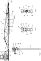
- das als Verteilerbalken ausgebildete Spritzgestänge in Ausbringposition einer als Pflanzenschutzspritze ausgebildeten landwirtschaftlichen Verteilmaschine in Teilansicht mit einer in Teilbereichen des Verteilerbalkens angebauten Schleppschlauchanordnung mit Schleppschläuchen in der Ansicht von hinten,
- Fig.2
- einen Schleppschlauch der Schleppschlauchanordnung gemäß
Fig.1 in der Ansicht von hinten und im vergrößerten Maßstab, - Fig. 3
- das einem Schleppschlauch zu geordnete Knickgelenk gemäß
Fig.1 und 2 in der Ansicht von rechts und im vergrößerten Maßstab, - Fig.4
- das einem Schleppschlauch zu geordnete Knickgelenk gemäß
Fig. 3 in der Ansicht von hinten, - Fig.5
- das als Verteilerbalken ausgebildete Spritzgestänge in aufrechter Transportstellung einer als Pflanzenschutzspritze ausgebildeten landwirtschaftlichen Verteilmaschine in Teilansicht mit einer in Teilbereichen des Verteilerbalkens angebauten Schleppschlauchanordnung mit Schleppschläuchen in der Ansicht von hinten,
- Fig.6
- einen Schleppschlauch der Schleppschlauchanordnung gemäß
Fig.5 in der Ansicht von hinten und im vergrößerten Maßstab, - Fig. 7
- das einem Schleppschlauch zu geordnete Knickgelenk gemäß
Fig.5 und 6 in der Ansicht von rechts und im vergrößerten Maßstab, - Fig.8
- das einem Schleppschlauch zu geordnete Knickgelenk gemäß
Fig.7 im Schnitt VIII - VIII und - Fig.9
- das einem Schleppschlauch zu geordnete Knickgelenk gemäß
Fig.7 im Schnitt IX - IX. - In der
Fig. 1 ist das als Verteilerbalken 1 ausgebildete Spritzgestänge in Ausbringposition einer als Pflanzenschutzspritze ausgebildeten landwirtschaftlichen Verteilmaschine dargestellt. Der Verteilerbalken 1 ist mittels einer Aufhängevorrichtung 2 in bekannter Weise verschwenkbar und höhenverstellbar an einem an dem nicht dargestellten Rahmen einer Pflanzenschutzspritze angeordneten Zwischenrahmen 3 angeordnet. In derFig.1 ist nur der rechte Teil des Verteilerbalkens 1 dargestellt. Der Verteilerbalken 1 besteht aus mehreren mittels Klappgelenken 4 miteinander verbundenen Sektionen 5. Der Verteilerbalken 1 kann aus der inFigur 1 dargestellten sich quer zur Fahrtrichtung in horizontaler Ausrichtung erstreckenden Ausbringposition in die inFig.5 , in der wiederum nur der rechte Teil des Verteilerbalkens 1 dargestellt ist, zusammengeklappte aufrechten Transportposition verbracht werden. - Auf der Unterseite des Verteilerbalkens 1 ist eine mit Flüssigkeit zu beaufschlagende Zuleitung 6 in bekannter Weise angeordnet. Dieser Zuleitung 6 werden in bekannter und daher nicht dargestellter Weise die auszubringenden Flüssigkeiten in dosierter Form zugeleitet. Die Zuleitung 6 weist in gleichmäßigen Abständen zueinander angeordnete Anschlusskupplungen 7 mit Flüssigkeitauslässen auf. An den Anschlusskupplung 7 der Flüssigkeitauslässe sind jeweils über Verbindungsvorrichtungen 8 jeweils Schleppschläuche 9 einer Schleppschlauchanordnung 10 zu befestigen. Die Anschlusskupplung 4 und die Verbindungsvorrichtung 8 sind bajonettartig ausgebildet. Somit können die Schleppschläuche 9 anstelle von Ausbringdüsen einfach an den jeweiligen Anschlusskupplungen 7 befestigt und gegeneinander ausgetauscht werden. In den
Fig.1 und5 sind der Übersichtlichkeit halber nur einige Schleppschläuchen 9 an den die Flüssigkeitauslässen aufweisende Anschlusskupplungen 7 des Verteilerbalkens 1 angeordnet. Selbstverständlich werden für das Ausbringen von Flüssigkeiten über Schleppschläuche 9 an allen Flüssigkeitauslässen aufweisende Anschlusskupplungen 7 des Verteilerbalkens 1 Schleppschläuche 9 angeordnet. Die Schleppschläuche 9 hängen in der Ausbringstellung des Spritzgestänges 1 von der Anschlusskupplung 7 zumindest annähernd senkrecht nach unten. - In dem Bereich der Verbindungsvorrichtung 8 ist jeweils ein Knickgelenk 11 in dem jeweiligen Schleppschlauch 9 in integrierter Weise angeordnet. Das jeweilige Knickgelenk 11 besteht aus zwei miteinander mittels eines Gelenkes 12 schwenkbar miteinander verbundenen und in Längsrichtung der Schleppschläuche 9 mit rohrartigen Aussparungen 13 versehenen Gelenkteilen 14 und 15. Die Gelenkachse 16 des Knickgelenkes 11 weist in Ausbringposition des Verteilerbalkens 1 in Fahrtrichtung. Hierdurch knickt das Knickgelenk 11 und somit der Schleppschlauch 9 während der Vorwärtsbewegung der Maschine nicht nach rückwärts ab.
- In den rohrartigen Aussparungen 13 der beiden Gelenkteile 14 und 15 des Knickgelenkes 11 ist ein weiches und leicht biegsames Schlauchstück 17 in abgedichteter Weise eingesetzt ist. Dieses Schlauchstück 17 kann ein Wellrohr, Wellschlauch oder Silikonschlauch sein.
- An dem oberen Gelenkteil 14 des Kickgelenkes 11 ist die bajonettartige Verbindungsvorrichtung 8 zur Anbringung an der den Flüssigkeitauslass aufweisenden Anschlusskupplung 7 der Zuleitung 6 und an dem unteren Gelenkteil 15 ist eine Schlauchtülle 18 zur Anordnung des Schleppschlauches 9 angeordnet. Der Schleppschlauch 9 kann in nicht dargestellter Weise mit einer Schlauchklemme auf der Schlauchtülle 18 gesichert sein.
- Wenn die einzelnen Sektionen 5 des Verteilerbalkens 1 mittels der Klappgelenke 4 in bekannter Weise paketartig zueinander eingeklappt und die paketartig zueinander geklappten Sektionen 5 des Verteilerbalkens 1 anschließend noch um zumindest annähernd 90° um eine zumindest annähernd in Fahrtrichtung verlaufende Gelenkachse 19 in eine aufrechte Stellung, wie in
Fig.5 dargestellt, in die Transportposition hoch geklappt sind, richten sich die einzelnen Schleppschläuche 9 aufgrund des Knickgelenkes 11 von der Verbindungsvorrichtung 8 aus nach unten hängend aus, wie dieFig. 5 und 6 zeigen. Hierzu ist der jeweilige Schleppschlauch 9 mittels des Knickgelenkes 11 aus seiner Ausbringposition gemäßFig. 1 bis 4 zumindest annähernd um 90° in seine Transportposition gemäßFig. 5 bis 9 verschwenkbar, wie die Zeichnungen zeigen. - Die Flexibilität und/oder Elastizität des weichen und leicht biegsamen Schlauchstückes 17, welches in den rohrartigen Aussparungen 13 der beiden Gelenkteile 14 und 15 des Knickgelenkes 11 eingesetzt ist, ist zumindest derartig ausgeprägt, dass das Knickgelenk 11 allein aufgrund der von der Masse des Schleppschlauches 9 ausgehenden Gewichtskraft, dass das Knickgelenk 11 aus seiner Ausbringposition gemäß
Fig.1 bis 4 um zumindest annähernd 90° in die in denFig. 5 bis 9 dargestellte Transportposition verschwenken kann.
Claims (7)
- Schleppschlauchanordnung (10) für landwirtschaftliche Verteilmaschinen zur Ausbringung von Flüssigkeiten zur Anbringung von vorzugsweise in sich flexiblen Schleppschläuchen (9) an einem in eine zumindest annähernd horizontale Ausrichtung in der Ausbringposition sich befindlichen und in zumindest eine zumindest annähernd aufrechte Transportposition verbringbaren Verteilerbalken (1), wobei die Schleppschläuche (9) jeweils mittels einer Verbindungsvorrichtung (8) an den Flüssigkeitsauslässen von zumindest einer an dem Verteilerbalken (1) angeordneten mit der auszubringenden Flüssigkeit beaufschlagten Zuleitung (6) angeschlossen sind, wobei die Schleppschläuche (9) in der aufrechten Transportposition des Verteilerbalkens (1) zumindest teilweise von der Verbindungsvorrichtung (8) aus nach unten hängend ausgerichtet sind, dadurch gekennzeichnet, dass jeweils in dem Bereich der Verbindungsvorrichtung (8) ein Knickgelenk (11) in dem Schleppschlauch (9) angeordnet ist, dass die jeweilige Gelenkachse (16) des Knickgelenkes (11) in Ausbringposition des Verteilerbalkens (1) in Fahrtrichtung weist.
- Schleppschlauchanordnung nach Anspruch 1, dadurch gekennzeichnet, dass das jeweilige Knickgelenk (11) aus zwei miteinander mittels eines Gelenkes (12) schwenkbar miteinander verbundenen und in Längsrichtung der Schleppschläuche (9) mit rohrartigen Aussparungen (13) versehenen Gelenkteilen (14,15) besteht.
- Schleppschlauchanordnung nach zumindest einem der vorstehenden Ansprüche, dadurch gekennzeichnet, dass in den rohrartigen Aussparungen (13) der beiden Gelenkteile (14,15) des Knickgelenkes (16) ein weiches und leicht biegsames Schlauchstück (17) in abgedichteter Weise eingesetzt ist.
- Schleppschlauchanordnung nach Anspruch 3, dadurch gekennzeichnet, dass das Schlauchstück (17) ein Wellrohr, Wellschlauch oder Silikonschlauch ist.
- Schleppschlauchanordnung nach zumindest einem der vorstehenden Ansprüche, dadurch gekennzeichnet, dass der jeweilige Schleppschlauch (9) mittels des Knickgelenkes (11) aus seiner Ausbringposition zumindest annähernd um 90° in seine Transportposition verschwenkbar ist.
- Schleppschlauchanordnung nach Anspruch 1, dadurch gekennzeichnet, dass an dem einen Gelenkteil (14) des Knickgelenkes (11) die Verbindungsvorrichtung (8) und an dem anderen Gelenkteil (15) eine Schlauchtülle (18) zur Anordnung des Schleppschlauches (9) angeordnet ist.
- Schleppschlauchanordnung nach zumindest einem der vorstehenden Ansprüche, dadurch gekennzeichnet, dass die Verbindungsvorrichtung (8) bajonettartig ausgestaltet ist.
Applications Claiming Priority (1)
| Application Number | Priority Date | Filing Date | Title |
|---|---|---|---|
| DE102016116522.0A DE102016116522A1 (de) | 2016-09-05 | 2016-09-05 | Schleppschlauchanordnung für landwirtschaftlche Verteilmaschinen zur Ausbringung von Flüssigkeiten |
Publications (2)
| Publication Number | Publication Date |
|---|---|
| EP3289849A1 true EP3289849A1 (de) | 2018-03-07 |
| EP3289849B1 EP3289849B1 (de) | 2019-03-20 |
Family
ID=59859022
Family Applications (1)
| Application Number | Title | Priority Date | Filing Date |
|---|---|---|---|
| EP17401097.5A Active EP3289849B1 (de) | 2016-09-05 | 2017-08-24 | Schleppschlauchanordnung für landwirtschaftlche verteilmaschinen zur ausbringung von flüssigkeiten |
Country Status (3)
| Country | Link |
|---|---|
| EP (1) | EP3289849B1 (de) |
| DE (1) | DE102016116522A1 (de) |
| DK (1) | DK3289849T3 (de) |
Citations (3)
| Publication number | Priority date | Publication date | Assignee | Title |
|---|---|---|---|---|
| DE4123790A1 (de) | 1991-07-18 | 1993-01-21 | Amazonen Werke Dreyer H | Schleppschlaeuche |
| DE29611254U1 (de) * | 1996-06-28 | 1996-09-12 | Alfa Laval Agri BSA GmbH, 95509 Marktschorgast | Gülle-Ausbringvorrichtung für Güllefahrzeuge |
| EP2705750A1 (de) * | 2012-09-06 | 2014-03-12 | Lemken GmbH & Co. KG | Schleppschlauchverband |
Family Cites Families (1)
| Publication number | Priority date | Publication date | Assignee | Title |
|---|---|---|---|---|
| DE10134061B4 (de) | 2001-07-13 | 2005-02-24 | Mosmatic Ag | Knickgelenk für Hochdruck-Reinigungsgeräte |
-
2016
- 2016-09-05 DE DE102016116522.0A patent/DE102016116522A1/de not_active Withdrawn
-
2017
- 2017-08-24 DK DK17401097.5T patent/DK3289849T3/da active
- 2017-08-24 EP EP17401097.5A patent/EP3289849B1/de active Active
Patent Citations (3)
| Publication number | Priority date | Publication date | Assignee | Title |
|---|---|---|---|---|
| DE4123790A1 (de) | 1991-07-18 | 1993-01-21 | Amazonen Werke Dreyer H | Schleppschlaeuche |
| DE29611254U1 (de) * | 1996-06-28 | 1996-09-12 | Alfa Laval Agri BSA GmbH, 95509 Marktschorgast | Gülle-Ausbringvorrichtung für Güllefahrzeuge |
| EP2705750A1 (de) * | 2012-09-06 | 2014-03-12 | Lemken GmbH & Co. KG | Schleppschlauchverband |
Also Published As
| Publication number | Publication date |
|---|---|
| DE102016116522A1 (de) | 2018-03-08 |
| EP3289849B1 (de) | 2019-03-20 |
| DK3289849T3 (da) | 2019-06-03 |
Similar Documents
| Publication | Publication Date | Title |
|---|---|---|
| EP3017698B1 (de) | Gülleverteiler | |
| EP0163154B1 (de) | Spritzvorrichtung zum Ausbringen von flüssigen Spritzmitteln | |
| DE102011053745A1 (de) | Mehrfachdüsenkörper für eine landwirtschaftliche Feldspritze | |
| DE2025039A1 (de) | Pneumatisch betriebene Maschine zum Verteilen körniger Stoffe | |
| EP3289849B1 (de) | Schleppschlauchanordnung für landwirtschaftlche verteilmaschinen zur ausbringung von flüssigkeiten | |
| DE3512992C2 (de) | Vorrichtung zum Streuen von schüttfähigem Gut, insbesondere Dünger | |
| DE102019133273A1 (de) | Landwirtschaftliche Ausbringmaschine | |
| EP0437801A1 (de) | Landwirtschaftliche Verteilmaschine | |
| EP3085219B1 (de) | Landwirtschaftliches gerät | |
| EP3476217B1 (de) | Verteilergestänge für eine pflanzenschutzspritze | |
| DE102017009830A1 (de) | Vorrichtung zum Ausbringen von Stoffgemischen | |
| EP2995184B1 (de) | Sämaschine | |
| DE3527614C2 (de) | ||
| DE102010016207A1 (de) | Landwirtschaftliche Pflanzenschutzspritze | |
| DE3300444A1 (de) | Maschine zum verteilen von koernigen materialien | |
| EP0958725B1 (de) | Landwirtschaftliche Verteilmaschine | |
| DE102007018294A1 (de) | Gezogenes landwirtschaftliches Arbeitsgerät | |
| DE2745522A1 (de) | Anbindevorrichtung fuer vieh | |
| DE1236851B (de) | Verlegbare Feldberegnungsanlage | |
| DE102005038786A1 (de) | Landwirtschaftliche Verteilmaschine | |
| DE19538588A1 (de) | Pneumatische Verteilmaschine | |
| DE3729538A1 (de) | Vorrichtung zum streuen von duenger | |
| DE3145113C2 (de) | Tankwagen zum Aufbringen von insbesondere Gülle auf landwirtschaftlich genutzte Bodenflächen | |
| DE7837911U1 (de) | Verlegewagen fuer strangfoermiges material | |
| DE1607357A1 (de) | Spritzgestaenge fuer Pflanzenschutzgeraete |
Legal Events
| Date | Code | Title | Description |
|---|---|---|---|
| PUAI | Public reference made under article 153(3) epc to a published international application that has entered the european phase |
Free format text: ORIGINAL CODE: 0009012 |
|
| STAA | Information on the status of an ep patent application or granted ep patent |
Free format text: STATUS: THE APPLICATION HAS BEEN PUBLISHED |
|
| AK | Designated contracting states |
Kind code of ref document: A1 Designated state(s): AL AT BE BG CH CY CZ DE DK EE ES FI FR GB GR HR HU IE IS IT LI LT LU LV MC MK MT NL NO PL PT RO RS SE SI SK SM TR |
|
| AX | Request for extension of the european patent |
Extension state: BA ME |
|
| STAA | Information on the status of an ep patent application or granted ep patent |
Free format text: STATUS: REQUEST FOR EXAMINATION WAS MADE |
|
| 17P | Request for examination filed |
Effective date: 20180516 |
|
| RBV | Designated contracting states (corrected) |
Designated state(s): AL AT BE BG CH CY CZ DE DK EE ES FI FR GB GR HR HU IE IS IT LI LT LU LV MC MK MT NL NO PL PT RO RS SE SI SK SM TR |
|
| GRAP | Despatch of communication of intention to grant a patent |
Free format text: ORIGINAL CODE: EPIDOSNIGR1 |
|
| STAA | Information on the status of an ep patent application or granted ep patent |
Free format text: STATUS: GRANT OF PATENT IS INTENDED |
|
| RIC1 | Information provided on ipc code assigned before grant |
Ipc: A01C 23/00 20060101AFI20180919BHEP Ipc: A01M 7/00 20060101ALI20180919BHEP |
|
| INTG | Intention to grant announced |
Effective date: 20181008 |
|
| GRAS | Grant fee paid |
Free format text: ORIGINAL CODE: EPIDOSNIGR3 |
|
| GRAA | (expected) grant |
Free format text: ORIGINAL CODE: 0009210 |
|
| STAA | Information on the status of an ep patent application or granted ep patent |
Free format text: STATUS: THE PATENT HAS BEEN GRANTED |
|
| AK | Designated contracting states |
Kind code of ref document: B1 Designated state(s): AL AT BE BG CH CY CZ DE DK EE ES FI FR GB GR HR HU IE IS IT LI LT LU LV MC MK MT NL NO PL PT RO RS SE SI SK SM TR |
|
| REG | Reference to a national code |
Ref country code: GB Ref legal event code: FG4D Free format text: NOT ENGLISH |
|
| REG | Reference to a national code |
Ref country code: CH Ref legal event code: EP |
|
| REG | Reference to a national code |
Ref country code: DE Ref legal event code: R096 Ref document number: 502017000968 Country of ref document: DE |
|
| REG | Reference to a national code |
Ref country code: AT Ref legal event code: REF Ref document number: 1109511 Country of ref document: AT Kind code of ref document: T Effective date: 20190415 |
|
| REG | Reference to a national code |
Ref country code: IE Ref legal event code: FG4D Free format text: LANGUAGE OF EP DOCUMENT: GERMAN |
|
| REG | Reference to a national code |
Ref country code: DK Ref legal event code: T3 Effective date: 20190528 |
|
| REG | Reference to a national code |
Ref country code: NL Ref legal event code: MP Effective date: 20190320 |
|
| PG25 | Lapsed in a contracting state [announced via postgrant information from national office to epo] |
Ref country code: NO Free format text: LAPSE BECAUSE OF FAILURE TO SUBMIT A TRANSLATION OF THE DESCRIPTION OR TO PAY THE FEE WITHIN THE PRESCRIBED TIME-LIMIT Effective date: 20190620 Ref country code: FI Free format text: LAPSE BECAUSE OF FAILURE TO SUBMIT A TRANSLATION OF THE DESCRIPTION OR TO PAY THE FEE WITHIN THE PRESCRIBED TIME-LIMIT Effective date: 20190320 Ref country code: LT Free format text: LAPSE BECAUSE OF FAILURE TO SUBMIT A TRANSLATION OF THE DESCRIPTION OR TO PAY THE FEE WITHIN THE PRESCRIBED TIME-LIMIT Effective date: 20190320 Ref country code: SE Free format text: LAPSE BECAUSE OF FAILURE TO SUBMIT A TRANSLATION OF THE DESCRIPTION OR TO PAY THE FEE WITHIN THE PRESCRIBED TIME-LIMIT Effective date: 20190320 |
|
| REG | Reference to a national code |
Ref country code: LT Ref legal event code: MG4D |
|
| PG25 | Lapsed in a contracting state [announced via postgrant information from national office to epo] |
Ref country code: BG Free format text: LAPSE BECAUSE OF FAILURE TO SUBMIT A TRANSLATION OF THE DESCRIPTION OR TO PAY THE FEE WITHIN THE PRESCRIBED TIME-LIMIT Effective date: 20190620 Ref country code: GR Free format text: LAPSE BECAUSE OF FAILURE TO SUBMIT A TRANSLATION OF THE DESCRIPTION OR TO PAY THE FEE WITHIN THE PRESCRIBED TIME-LIMIT Effective date: 20190621 Ref country code: HR Free format text: LAPSE BECAUSE OF FAILURE TO SUBMIT A TRANSLATION OF THE DESCRIPTION OR TO PAY THE FEE WITHIN THE PRESCRIBED TIME-LIMIT Effective date: 20190320 Ref country code: NL Free format text: LAPSE BECAUSE OF FAILURE TO SUBMIT A TRANSLATION OF THE DESCRIPTION OR TO PAY THE FEE WITHIN THE PRESCRIBED TIME-LIMIT Effective date: 20190320 Ref country code: RS Free format text: LAPSE BECAUSE OF FAILURE TO SUBMIT A TRANSLATION OF THE DESCRIPTION OR TO PAY THE FEE WITHIN THE PRESCRIBED TIME-LIMIT Effective date: 20190320 Ref country code: LV Free format text: LAPSE BECAUSE OF FAILURE TO SUBMIT A TRANSLATION OF THE DESCRIPTION OR TO PAY THE FEE WITHIN THE PRESCRIBED TIME-LIMIT Effective date: 20190320 |
|
| PG25 | Lapsed in a contracting state [announced via postgrant information from national office to epo] |
Ref country code: RO Free format text: LAPSE BECAUSE OF FAILURE TO SUBMIT A TRANSLATION OF THE DESCRIPTION OR TO PAY THE FEE WITHIN THE PRESCRIBED TIME-LIMIT Effective date: 20190320 Ref country code: CZ Free format text: LAPSE BECAUSE OF FAILURE TO SUBMIT A TRANSLATION OF THE DESCRIPTION OR TO PAY THE FEE WITHIN THE PRESCRIBED TIME-LIMIT Effective date: 20190320 Ref country code: SK Free format text: LAPSE BECAUSE OF FAILURE TO SUBMIT A TRANSLATION OF THE DESCRIPTION OR TO PAY THE FEE WITHIN THE PRESCRIBED TIME-LIMIT Effective date: 20190320 Ref country code: ES Free format text: LAPSE BECAUSE OF FAILURE TO SUBMIT A TRANSLATION OF THE DESCRIPTION OR TO PAY THE FEE WITHIN THE PRESCRIBED TIME-LIMIT Effective date: 20190320 Ref country code: PT Free format text: LAPSE BECAUSE OF FAILURE TO SUBMIT A TRANSLATION OF THE DESCRIPTION OR TO PAY THE FEE WITHIN THE PRESCRIBED TIME-LIMIT Effective date: 20190720 Ref country code: AL Free format text: LAPSE BECAUSE OF FAILURE TO SUBMIT A TRANSLATION OF THE DESCRIPTION OR TO PAY THE FEE WITHIN THE PRESCRIBED TIME-LIMIT Effective date: 20190320 Ref country code: EE Free format text: LAPSE BECAUSE OF FAILURE TO SUBMIT A TRANSLATION OF THE DESCRIPTION OR TO PAY THE FEE WITHIN THE PRESCRIBED TIME-LIMIT Effective date: 20190320 |
|
| PG25 | Lapsed in a contracting state [announced via postgrant information from national office to epo] |
Ref country code: SM Free format text: LAPSE BECAUSE OF FAILURE TO SUBMIT A TRANSLATION OF THE DESCRIPTION OR TO PAY THE FEE WITHIN THE PRESCRIBED TIME-LIMIT Effective date: 20190320 Ref country code: PL Free format text: LAPSE BECAUSE OF FAILURE TO SUBMIT A TRANSLATION OF THE DESCRIPTION OR TO PAY THE FEE WITHIN THE PRESCRIBED TIME-LIMIT Effective date: 20190320 |
|
| PG25 | Lapsed in a contracting state [announced via postgrant information from national office to epo] |
Ref country code: IS Free format text: LAPSE BECAUSE OF FAILURE TO SUBMIT A TRANSLATION OF THE DESCRIPTION OR TO PAY THE FEE WITHIN THE PRESCRIBED TIME-LIMIT Effective date: 20190720 |
|
| REG | Reference to a national code |
Ref country code: DE Ref legal event code: R097 Ref document number: 502017000968 Country of ref document: DE |
|
| PLBE | No opposition filed within time limit |
Free format text: ORIGINAL CODE: 0009261 |
|
| STAA | Information on the status of an ep patent application or granted ep patent |
Free format text: STATUS: NO OPPOSITION FILED WITHIN TIME LIMIT |
|
| 26N | No opposition filed |
Effective date: 20200102 |
|
| PG25 | Lapsed in a contracting state [announced via postgrant information from national office to epo] |
Ref country code: SI Free format text: LAPSE BECAUSE OF FAILURE TO SUBMIT A TRANSLATION OF THE DESCRIPTION OR TO PAY THE FEE WITHIN THE PRESCRIBED TIME-LIMIT Effective date: 20190320 |
|
| PG25 | Lapsed in a contracting state [announced via postgrant information from national office to epo] |
Ref country code: TR Free format text: LAPSE BECAUSE OF FAILURE TO SUBMIT A TRANSLATION OF THE DESCRIPTION OR TO PAY THE FEE WITHIN THE PRESCRIBED TIME-LIMIT Effective date: 20190320 |
|
| PG25 | Lapsed in a contracting state [announced via postgrant information from national office to epo] |
Ref country code: LU Free format text: LAPSE BECAUSE OF NON-PAYMENT OF DUE FEES Effective date: 20190824 Ref country code: MC Free format text: LAPSE BECAUSE OF FAILURE TO SUBMIT A TRANSLATION OF THE DESCRIPTION OR TO PAY THE FEE WITHIN THE PRESCRIBED TIME-LIMIT Effective date: 20190320 |
|
| REG | Reference to a national code |
Ref country code: BE Ref legal event code: MM Effective date: 20190831 |
|
| PG25 | Lapsed in a contracting state [announced via postgrant information from national office to epo] |
Ref country code: IE Free format text: LAPSE BECAUSE OF NON-PAYMENT OF DUE FEES Effective date: 20190824 |
|
| PG25 | Lapsed in a contracting state [announced via postgrant information from national office to epo] |
Ref country code: BE Free format text: LAPSE BECAUSE OF NON-PAYMENT OF DUE FEES Effective date: 20190831 |
|
| REG | Reference to a national code |
Ref country code: CH Ref legal event code: PL |
|
| PG25 | Lapsed in a contracting state [announced via postgrant information from national office to epo] |
Ref country code: LI Free format text: LAPSE BECAUSE OF NON-PAYMENT OF DUE FEES Effective date: 20200831 Ref country code: CH Free format text: LAPSE BECAUSE OF NON-PAYMENT OF DUE FEES Effective date: 20200831 |
|
| REG | Reference to a national code |
Ref country code: DE Ref legal event code: R081 Ref document number: 502017000968 Country of ref document: DE Owner name: AMAZONEN-WERKE H. DREYER SE & CO. KG, DE Free format text: FORMER OWNER: AMAZONEN-WERKE H. DREYER GMBH & CO. KG, 49205 HASBERGEN, DE |
|
| PG25 | Lapsed in a contracting state [announced via postgrant information from national office to epo] |
Ref country code: CY Free format text: LAPSE BECAUSE OF FAILURE TO SUBMIT A TRANSLATION OF THE DESCRIPTION OR TO PAY THE FEE WITHIN THE PRESCRIBED TIME-LIMIT Effective date: 20190320 |
|
| PG25 | Lapsed in a contracting state [announced via postgrant information from national office to epo] |
Ref country code: HU Free format text: LAPSE BECAUSE OF FAILURE TO SUBMIT A TRANSLATION OF THE DESCRIPTION OR TO PAY THE FEE WITHIN THE PRESCRIBED TIME-LIMIT; INVALID AB INITIO Effective date: 20170824 Ref country code: MT Free format text: LAPSE BECAUSE OF FAILURE TO SUBMIT A TRANSLATION OF THE DESCRIPTION OR TO PAY THE FEE WITHIN THE PRESCRIBED TIME-LIMIT Effective date: 20190320 |
|
| GBPC | Gb: european patent ceased through non-payment of renewal fee |
Effective date: 20210824 |
|
| PG25 | Lapsed in a contracting state [announced via postgrant information from national office to epo] |
Ref country code: MK Free format text: LAPSE BECAUSE OF FAILURE TO SUBMIT A TRANSLATION OF THE DESCRIPTION OR TO PAY THE FEE WITHIN THE PRESCRIBED TIME-LIMIT Effective date: 20190320 |
|
| PG25 | Lapsed in a contracting state [announced via postgrant information from national office to epo] |
Ref country code: GB Free format text: LAPSE BECAUSE OF NON-PAYMENT OF DUE FEES Effective date: 20210824 |
|
| P01 | Opt-out of the competence of the unified patent court (upc) registered |
Effective date: 20230523 |
|
| REG | Reference to a national code |
Ref country code: AT Ref legal event code: MM01 Ref document number: 1109511 Country of ref document: AT Kind code of ref document: T Effective date: 20220824 |
|
| PG25 | Lapsed in a contracting state [announced via postgrant information from national office to epo] |
Ref country code: AT Free format text: LAPSE BECAUSE OF NON-PAYMENT OF DUE FEES Effective date: 20220824 |
|
| PGFP | Annual fee paid to national office [announced via postgrant information from national office to epo] |
Ref country code: DK Payment date: 20250814 Year of fee payment: 9 Ref country code: DE Payment date: 20250702 Year of fee payment: 9 |
|
| PGFP | Annual fee paid to national office [announced via postgrant information from national office to epo] |
Ref country code: IT Payment date: 20250722 Year of fee payment: 9 |
|
| PGFP | Annual fee paid to national office [announced via postgrant information from national office to epo] |
Ref country code: FR Payment date: 20250703 Year of fee payment: 9 |