EP3289646B1 - Connexion par enfichage et jeu de connexions par enfichage - Google Patents
Connexion par enfichage et jeu de connexions par enfichage Download PDFInfo
- Publication number
- EP3289646B1 EP3289646B1 EP16717256.8A EP16717256A EP3289646B1 EP 3289646 B1 EP3289646 B1 EP 3289646B1 EP 16717256 A EP16717256 A EP 16717256A EP 3289646 B1 EP3289646 B1 EP 3289646B1
- Authority
- EP
- European Patent Office
- Prior art keywords
- coding
- plug
- connector
- plug connection
- coding element
- Prior art date
- Legal status (The legal status is an assumption and is not a legal conclusion. Google has not performed a legal analysis and makes no representation as to the accuracy of the status listed.)
- Active
Links
- 238000003780 insertion Methods 0.000 claims description 39
- 230000037431 insertion Effects 0.000 claims description 39
- 238000010168 coupling process Methods 0.000 claims description 21
- 238000005859 coupling reaction Methods 0.000 claims description 21
- 230000008878 coupling Effects 0.000 claims description 20
- 230000000295 complement effect Effects 0.000 claims description 19
- 239000004020 conductor Substances 0.000 claims description 18
- 230000007246 mechanism Effects 0.000 claims description 17
- 230000013011 mating Effects 0.000 description 6
- 229910052751 metal Inorganic materials 0.000 description 4
- 239000002184 metal Substances 0.000 description 4
- 238000000034 method Methods 0.000 description 4
- 230000008569 process Effects 0.000 description 4
- 230000008054 signal transmission Effects 0.000 description 4
- 229910052782 aluminium Inorganic materials 0.000 description 2
- XAGFODPZIPBFFR-UHFFFAOYSA-N aluminium Chemical compound [Al] XAGFODPZIPBFFR-UHFFFAOYSA-N 0.000 description 2
- 230000004323 axial length Effects 0.000 description 2
- 239000000463 material Substances 0.000 description 2
- 230000009471 action Effects 0.000 description 1
- 230000008901 benefit Effects 0.000 description 1
- 230000005540 biological transmission Effects 0.000 description 1
- 230000015572 biosynthetic process Effects 0.000 description 1
- 210000000078 claw Anatomy 0.000 description 1
- 230000007423 decrease Effects 0.000 description 1
- 230000003247 decreasing effect Effects 0.000 description 1
- 230000001419 dependent effect Effects 0.000 description 1
- 238000011161 development Methods 0.000 description 1
- 230000018109 developmental process Effects 0.000 description 1
- 238000009434 installation Methods 0.000 description 1
- 239000012212 insulator Substances 0.000 description 1
Images

Classifications
-
- H—ELECTRICITY
- H01—ELECTRIC ELEMENTS
- H01R—ELECTRICALLY-CONDUCTIVE CONNECTIONS; STRUCTURAL ASSOCIATIONS OF A PLURALITY OF MUTUALLY-INSULATED ELECTRICAL CONNECTING ELEMENTS; COUPLING DEVICES; CURRENT COLLECTORS
- H01R13/00—Details of coupling devices of the kinds covered by groups H01R12/70 or H01R24/00 - H01R33/00
- H01R13/64—Means for preventing incorrect coupling
- H01R13/645—Means for preventing incorrect coupling by exchangeable elements on case or base
- H01R13/6456—Means for preventing incorrect coupling by exchangeable elements on case or base comprising keying elements at different positions along the periphery of the connector
-
- H—ELECTRICITY
- H01—ELECTRIC ELEMENTS
- H01R—ELECTRICALLY-CONDUCTIVE CONNECTIONS; STRUCTURAL ASSOCIATIONS OF A PLURALITY OF MUTUALLY-INSULATED ELECTRICAL CONNECTING ELEMENTS; COUPLING DEVICES; CURRENT COLLECTORS
- H01R13/00—Details of coupling devices of the kinds covered by groups H01R12/70 or H01R24/00 - H01R33/00
- H01R13/62—Means for facilitating engagement or disengagement of coupling parts or for holding them in engagement
- H01R13/629—Additional means for facilitating engagement or disengagement of coupling parts, e.g. aligning or guiding means, levers, gas pressure electrical locking indicators, manufacturing tolerances
- H01R13/631—Additional means for facilitating engagement or disengagement of coupling parts, e.g. aligning or guiding means, levers, gas pressure electrical locking indicators, manufacturing tolerances for engagement only
- H01R13/6315—Additional means for facilitating engagement or disengagement of coupling parts, e.g. aligning or guiding means, levers, gas pressure electrical locking indicators, manufacturing tolerances for engagement only allowing relative movement between coupling parts, e.g. floating connection
-
- H—ELECTRICITY
- H01—ELECTRIC ELEMENTS
- H01R—ELECTRICALLY-CONDUCTIVE CONNECTIONS; STRUCTURAL ASSOCIATIONS OF A PLURALITY OF MUTUALLY-INSULATED ELECTRICAL CONNECTING ELEMENTS; COUPLING DEVICES; CURRENT COLLECTORS
- H01R24/00—Two-part coupling devices, or either of their cooperating parts, characterised by their overall structure
- H01R24/38—Two-part coupling devices, or either of their cooperating parts, characterised by their overall structure having concentrically or coaxially arranged contacts
-
- H—ELECTRICITY
- H01—ELECTRIC ELEMENTS
- H01R—ELECTRICALLY-CONDUCTIVE CONNECTIONS; STRUCTURAL ASSOCIATIONS OF A PLURALITY OF MUTUALLY-INSULATED ELECTRICAL CONNECTING ELEMENTS; COUPLING DEVICES; CURRENT COLLECTORS
- H01R2103/00—Two poles
Definitions
- the present invention relates to a connector which consists of a connector and a slot for inserting the connector.
- a first coding element with a coding pattern is arranged on the plug connector, and a second coding element with a coding pattern complementary to the coding pattern is arranged on the slot, such that the plug connector can be inserted into the slot in a plugging direction up to a coupling position, if the first Coding element and the second coding element occupy a predetermined relative position to each other,
- Coded connectors are known in the art. In such connectors, a coding mechanism ensures that the connector can only be plugged into a correct slot assigned to it. In this way, it can be prevented in the presence of multiple slots that a connector can be inserted incorrectly in a slot not assigned to him, resulting in a faulty power or signal transmission result. Coded connectors are well known in the field of signal transmission to ensure that individual lines of a bundle of signal transmission lines are correctly coupled to associated receptacles. Coded connectors are also used in power transmission connectors to prevent connection errors during their installation.
- a slot is understood to be any connector receptacle that is configured to be coupled to the connector so that electrical currents from the connector can be routed through the slot.
- Examples of slots include a stationary receptacle, a receptacle assembly with multiple receptacles, a mating connector assembly, a mating connector, which may be located at a cable end or the like.
- the connector has a first coding element with a coding pattern
- the slot has a second coding element with a complementary coding pattern matching the coding pattern.
- the mating pattern may be in the form of a predetermined spatial arrangement of projections and / or recesses on the connector, which is adapted to engage with a complementary spatial arrangement of recesses and / or projections on the slot. Accordingly, the connector can be verkuppelt with the coding pattern in the plugging direction with the mating connector with the complementary coding pattern, provided that the connector and the slot are arranged relative to each other such that the coding pattern engages correctly when plugging into the complementary coding pattern.
- EP2822106 A1 discloses a connector according to the preamble of claim 1.
- contact elements of the connector and slot are in electrical contact, and the connector is in an axial end position at the slot.
- the first coding element is held rotatably on the plug connector about a rotation axis extending parallel to the plug-in direction and / or the second coding element is held rotatably about the rotation axis on the plug-in slot.
- the first coding element is rotatably supported on the connector about an axis of rotation extending parallel to the plug-in direction
- the second coding element is rotatably held on the slot about an axis of rotation parallel to the plug-in direction
- the first and second coding elements are rotatably supported on the connector and on the slot, respectively.
- the invention is based on the knowledge that in conventional plug connections from the cable installer often several relative rotational positions between connector and slot must be tested through to the Coding pattern correct position in the complementary coding pattern engages and the insertion process is made possible. Rotations of the entire slot and rotations of the connector to which a stiffening cable is regularly attached, however, are troublesome and can lead to damage to the connector. In contrast, it is sufficient in the connector according to the invention to rotate only the first and / or the second coding element such that it is aligned in the correct position with respect to. The other coding element, whereupon a plug-in operation is possible. A rotation of the main body of the connector with attached cable or a rotation of the entire slot, however, are not required according to the invention.
- the rotatable first coding element and / or the rotatable second coding element are preferably held on the connector or in the slot, that the coding pattern is readily recognizable by the cable fitter and / or the cable fitter is accessible for rotation. This facilitates the setting of the predetermined relative position between the connector and the slot prior to insertion and the correct selection of a connector belonging to a slot in the case of multiple connectors.
- the first coding element forms an outer boundary surface of the connector, is easily visible prior to insertion and / or is preferably exposed radially outward.
- the plug-in connection has a self-aligning mechanism, by means of which the first coding element and the second coding element are automatically rotated relative to one another in the predetermined relative position when the plug-in connector is inserted.
- This self-alignment between the two coding elements can be effected by a relative force acting upon insertion in the plugging direction between the two coding elements.
- the self-aligning mechanism includes a force deflecting mechanism for converting a plug-in force directed in the plugging direction into one of the coding elements in the circumferential direction aligning torque.
- the contour of the connector and / or the slot in a direction perpendicular to the insertion direction cutting plane is substantially round, preferably substantially rotationally symmetrical, and in particular approximately circular.
- Conventional coded connectors with a round contour prepare due to the numerous plausible appearing relative rotational positions between connector and slot special plug-in problems that can be eliminated by the Disausrichtmechanismus invention.
- the first coding element is a ring element revolving around a main body of the connector and rotatably held on the main body.
- the second coding element is a sleeve part rotatably held on the slot for insertion of the ring element.
- an outer diameter of the ring element is preferably adapted to an inner diameter of the sleeve part, so that the ring element can be inserted into the sleeve part under radial engagement of the coding pattern of the ring element in the complementary coding pattern of the sleeve part.
- the first coding element is a sleeve portion rotatably supported on a main body of the connector
- the second coding element is a ring member rotatably supported on the slot, which mates with the sleeve portion
- the ring member is not necessarily a circumferentially closed ring, but may also be partially annular or slotted so that it can be applied or clipped from the side of the connector.
- the ring member is so in a circumferential groove of the main body of the Connector held that it is fixed in the insertion direction in the groove, but is rotatable in the circumferential direction in the groove around the main body. It can be provided with a view to a good fixation of the ring member while providing a reliable coding mechanism that the depth of the groove is adapted to a radial ring thickness of the ring member, said provided on the ring member coding pattern projects radially out of the groove.
- the ring member is formed of a plastic material, wherein the groove may be incorporated into a main body made of a metal such as aluminum.
- the groove can be introduced into a metal outer conductor part of the connector.
- the sleeve part is formed from a plastic material and / or rotatably attached to a socket part of the slot made of metal.
- a rotary bearing may be provided, which may be formed, for example, by a radially engaging in an annular groove annular projection.
- the ring element has the coding pattern, which is preferably formed in the form of a predetermined spatial arrangement of projections and / or grooves
- the sleeve part has the complementary coding pattern, which is preferably in the form of a negative form of the coding pattern and a complementary spatial Arrangement of projections and / or grooves.
- the first coding pattern is in the form of preferably a plurality of radially outwardly projecting projections, and / or the second coding pattern in the form of preferably a plurality of guide grooves for inserting a respective projection is formed, or vice versa.
- the projections preferably project outward in the radial direction from a ring section of the ring element.
- the guide grooves preferably run at least in sections along the insertion direction in the inner wall of the sleeve part, wherein the distances between respectively adjacent projections of the ring element are adapted to the distances between each adjacent guide grooves of the sleeve part.
- An easily manufactured and reliable encoding mechanism can be provided by having the first coding pattern and the second coding pattern having multiple radial symmetry such as 2-fold, 3-fold, or 4-fold radial symmetry.
- the ring member has two preferably identically shaped protrusions at an angle of 180 °, three protrusions at an adjacent angle of 120 °, four protrusions at an adjacent angle of 90 ° or the like. on. The same applies to the introduced into the sleeve part guide.
- An encoding mechanism with n-fold radial symmetry offers the advantage of n predetermined relative positions, in each case an insertion process is possible.
- the first coding element is a ring element with two, three or more radially projecting and circumferentially spaced from each other at a predetermined angle projections.
- the second coding element is a sleeve part with two, three or more introduced into an inner wall of the sleeve part and in Circumferential direction each spaced below the predetermined angle spaced from each other guide grooves.
- a reliably acting self-alignment mechanism can be provided by at least partially reducing the width of at least one guide groove in the plug-in direction.
- the engaging in a wide inlet portion of the guide during insertion projection is namely guided by the tapered groove walls in the course of further insertion into a narrow groove portion, while align the coding correctly to each other, so that the connector to the coupling position in the slot is insertable.
- the self-aligning mechanism can be further improved in that the at least one guide groove - and preferably all guide grooves - has an inlet section with decreasing groove width in the plugging direction and a guide section with a substantially constant groove width adjoining the inlet section in the plugging direction.
- the groove width is preferably substantially conformed to a width of an associated projection, so that the two coding elements are substantially non-rotatably connected to each other when the projection is disposed in the guide portion - the coding pattern and the complementary coding pattern are interlocked.
- the width of the projections in the circumferential direction between 0.5 mm and 10 mm, in particular between 1 mm and 3 mm.
- the width of the guide portions of the guide grooves in the circumferential direction is preferably between 1 mm and 11 mm, in particular between 1.5 mm and 4 mm, so that the projections fit into the guide portions with a small clearance.
- the axial length of the inlet sections of the guide grooves is preferably more than 1 mm and less than 20 mm, particularly preferably between 3 mm and 10 mm.
- the axial length of the guide portions of the guide grooves with substantially constant groove width is preferably more than 10 mm and less than 50 mm, more preferably between 20 mm and 30 mm.
- n (n> 1) guide grooves into the sleeve member, with the guide grooves at the front wide end of the tapered inlet portion each covering a circumferential angular range of about 360 ° / n such that the groove walls adjacent guide grooves at the front end directly adjacent to each other or merge into each other.
- n (n> 1) guide grooves into the sleeve member, with the guide grooves at the front wide end of the tapered inlet portion each covering a circumferential angular range of about 360 ° / n such that the groove walls adjacent guide grooves at the front end directly adjacent to each other or merge into each other.
- the guide grooves in the inlet section taper in a symmetrical manner on both sides in the direction of the respective guide section of the guide groove.
- the second coding element has one or more abutment surfaces, each having a course component in the circumferential direction and a course component in the plug-in direction, wherein upon insertion of the connector, the first coding element abuts against the stop surface and at a relative rotation between the first and the second coding element slides.
- each abutment surface extends over a fraction of a full revolution substantially in the manner of a helix.
- these stop surfaces are formed by the side walls of the guide grooves in the inlet section.
- the slot is formed in the form of a socket.
- the slot may have a press-fit ring for pressing into a socket part and the rotatably mounted on the press-fitting ring and sleeve-shaped projecting in the direction of the connector second coding element.
- the press-in ring can by press action in the likewise sleeve-shaped Socket part to be pressed and has for this purpose on the friction during pressing on improving knurling.
- the press-fit is held firmly after pressing on the female part, while the coding element is rotatable with respect to.
- the arrangement of press-fit and female part is held.
- the female part has an axial dimension which allows complete reception of the second coding element inside the female part.
- the connector may be configured to carry high current or alternatively to transmit signals. In the case of a high-current connector, this is preferably connected to a preferably shielded high-current cable.
- the connector has at least one connected to an inner conductor of the cable and preferably crimped inner conductor contact and the inner conductor contact at least partially circumferential outer conductor, which may be pressed with an outer conductor of the cable.
- the first coding element is arranged on the outer boundary surface of the outer conductor.
- the connector is configured as a permanent connection.
- An "unsolvable" plug-in connection is to be understood as meaning that a coupling can be done manually merely by plugging in, but decoupling is then no longer possible or only possible with the aid of a tool.
- the plug-in connection can have snap-action or latching elements which engage inseparably before or when the coupling position is reached.
- a coding mechanism is particularly important in a permanent connection, since incorrectly verkuppelte connectors are no longer easily decoupled.
- the connector has one or more latching projections and the slot has a circumferential latching groove for engaging the latching projections.
- the latching projections may be provided on a latching ring surrounding the plug connector, and the latching groove may be introduced into the inner wall of the socket part of the slot.
- the present invention relates to a set of plug connections according to the invention.
- a "sentence" is understood to mean two, three, four or more plug-in connections according to the invention.
- the coding patterns and the complementary coding patterns of a first and a second connector of the set are each different from each other such that the connector of the first connector in the slot of the first connector, but not in the slot of the second connector is inserted to the coupling position.
- the connector comprises three or more plug-in connections according to the invention, the plug-in connectors of which can each be inserted in exactly one associated slot up to the coupling position.
- an inventive set on several pairs of connectors and associated slots which can be verkuppelt only due to the existing coding mechanism in each case in the correct manner.
- the coding pattern prevents misconnection of a connector of a first connector to a connector of a second connector.
- a simple coupling is possible because the encoding elements having coding elements are rotatable so that not the entire connector or the entire slot must be rotated to arrange in the predetermined relative position.
- the individual connectors additionally each have a self-aligning mechanism, a particularly simple coupling is possible because when inserting the connector of a connector in the slot of this connector, the first coding element and the second coding element are automatically rotated to each other in the predetermined relative position.
- it is apparent to the fitter immediately at the first attempt to plug in that a connector and a slot do not belong to the same connector if no self-alignment takes place and plugging into the coupling position is therefore not possible.
- An inventive set of connectors consists, for example, of three connectors for transmitting the U, V and W phases of a three-phase alternating current, for example.
- FIG. 1 An inventive connector 100 of a connector 10 and a slot 50 is in Fig. 1 shown.
- the connector is in Fig. 2 particularly clearly illustrated:
- the connector 10 is a high current connector with an inner conductor contact 22 for transmitting high current, eg. 50 A, 100 A or more.
- the connector 10 is connected to a cable end of a shielded high current cable 20.
- an insulator part 23 is arranged between the inner conductor contact 22 and the outer conductor 24 of the connector.
- the connector has no external conductor contact and / or is set up for the transmission of signals.
- the connector may also have more than one inner conductor contact, for example one or more differential contact pairs.
- the connector 10 has a first coding element 12 in the form of a ring element 13, which rotates around a main body 11 of the connector.
- the ring element is arranged in a circumferential groove, which is introduced into the main body 11 of the connector - here in the outer conductor 24 of the connector.
- the ring element 13 is a slotted plastic ring, so that it can be applied on the one hand from the side of the main body 11 and on the other hand slides well in the groove.
- the ring element 13 is arranged rotatably on the plug connector 10 about an axis of rotation A extending centrally through the plug connector 10 in the axial direction.
- the ring element 13 has a plurality of radially outwardly projecting projections 14, through which a coding pattern is formed.
- the protrusions protrude out of the groove so that when they are inserted into the slot 50 they can be brought into engagement with a complementary coding pattern formed by guide grooves.
- the ring member 13 a total of four projections 14 which project at an angle of 90 ° to the respective adjacent projection 14.
- the coding pattern has a 4-fold radial symmetry.
- two, three or more than four projections are provided on the ring member, which may project radially symmetrically from the ring member.
- the protrusions are not radiärsymmetrisch from the ring member; Rather, not all angles between adjacent protrusions are the same.
- the projections in the circumferential direction are not necessarily all the same width. It will be readily understood by those skilled in the art that numerous different coding patterns may be provided on the ring member 13 in this manner.
- Slot 50 is in Fig. 3 illustrated particularly clearly: The slot is essentially socket-shaped or hollow cylindrical and set up for insertion of the connector 10 in the insertion direction S to a coupling position. In the coupling position, the inner conductor contact 22 of the connector 10 is in electrical contact with a mating contact (not shown) of the slot 50th
- the slot 50 shown has a press-in 51, which is pressed into a socket part 53 (see Fig. 1 ).
- the press-fit ring or the socket part can be knurled in sections.
- a sleeve part 55 is held such that the sleeve part 55 is rotatable relative to the press-fit ring 51 and the bushing part 53 about the axis of rotation A.
- the Sleeve part 55 is made of plastic, while the press-fit ring and the socket part made of metal such as aluminum.
- a second coding element 5 2 is formed with a coding pattern complementary to the coding pattern, which is arranged rotatably on the slot 50.
- a rotation mechanism between the press-in ring 51 and the sleeve part 55 is provided.
- FIG. 3 the arrangement of Einpressring 51 and sleeve member 55 without the sleeve 53 is shown in perspective.
- the slot 50 may have a structure different from the structure shown in the figures.
- the coding element 52 is complementary to the coding pattern of the connector coding pattern, which allows engagement of the two coding elements upon insertion of the connector 10, and by the insertion of a connector is prevented with an unrelated coding pattern.
- both the second coding element 52 is rotatably held on the slot 50 and the first coding element 12 rotatably held on the connector 10. In other embodiments, either only the first coding element or only the second coding element is rotatable.
- the complementary coding pattern introduced into the second coding element 52 is particularly clear in FIG Fig. 3 illustrated:
- the inner wall 56 of the sleeve part has a plurality of extending in the direction of insertion S guide grooves 54 which are each adapted to engage a projection 14 of the connector 10.
- the number and the respective distance of the guide grooves 54 corresponds to the number and the respective spacing of the projections 14, so that each projection 14 during Inserting the connector 10 in the sleeve member 55 can engage radially in a guide groove 54.
- Each guide groove 54 has two sections: an inlet portion 62 facing the connector 10, in which the width B of the groove gradually decreases, and a guide portion 64 adjoining the inlet portion 62 in the insertion direction S, in which the width of the guide groove is substantially constant and adapted to the width of the associated projection 14.
- each guide groove 54 at the front end of the inlet portion 62 corresponds to a total angular range of 90 ° or an angular range of 360 ° / n in a total of four or n guide grooves 54, so that regardless of the relative starting rotational position between the first Coding element 12 and the second coding element 52 a shrinkage of the projections 14 in each case one of the guide grooves 54 is ensured.
- cover all guide grooves at the front end of the sleeve part an angular range of 360 ° and then preferably taper symmetrically on both sides in the direction of the respective guide portion 64th
- a self-aligning mechanism is provided, which ensures that upon insertion of the connector into the slot, the first coding element and the second coding element are automatically rotated in the predetermined relative position to each other.
- the projections 14 namely hit when inserting the connector 10 to the tapered groove walls are formed by the abutment surfaces 68, so that in the insertion direction S directed insertion force is converted into a rotational force between the two coding elements 12, 52.
- FIG. 2 an inventive connector 10 is shown in a perspective view.
- the connector 10 is arranged for permanent connection to the slot 50 and has for this purpose an annular claw member 80 with locking projections 82 for engagement in a detent recess 84 of the slot. From the Verkupplungs ein the connector 10 is only solvable by means of a tool.
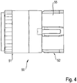
- an inventive slot 50 is shown in a perspective view and in a side view.
- the invention further comprises a set of plug-in connections according to the invention, each with different coding patterns and complementary coding patterns, so that each plug-in connector can only be plugged into the slot assigned to it so that no incorrect connections can occur.
Claims (13)
- Connexion d'enfichage (100) comportant :au moins un connecteur d'enfichage (10) avec un premier élément de codage (12) disposé sur celui-ci et pourvu d'un motif de codage, etun logement d'enfichage (50) avec un second élément de codage (52) disposé sur celui-ci et pourvu d'un motif de codage complémentaire audit motif de codage,dans laquellele connecteur d'enfichage (10) est enfichable dans une direction d'enfichage (S) jusqu'à une position de couplage dans le logement d'enfichage (50) lorsque le premier élément de codage (12) et le second élément de codage (52) occupent une position relative donnée l'un par rapport à l'autre,caractérisée en ce quele premier élément de codage (12) est maintenu sur le connecteur d'enfichage (10) de façon mobile en rotation autour d'un axe de rotation (A) s'étendant parallèlement à la direction d'enfichage (S), et/ou le second élément de codage (52) est maintenu sur le logement d'enfichage (50) de façon mobile en rotation autour de l'axe de rotation (A), etcaractérisée par un mécanisme d'auto-alignement par lequel, lors de l'enfichage du connecteur d'enfichage (10), le premier élément de codage (12) et le second élément de codage (52) sont tournés automatiquement jusque dans la position relative donnée l'un par rapport à l'autre.
- Connexion d'enfichage selon la revendication 1,
caractérisée en ce que
le premier élément de codage (12) est un élément annulaire (13) entourant un corps principal (11) du connecteur d'enfichage, et/ou le second élément de codage (52) est une partie de douille (55) maintenue mobile en rotation sur le logement d'enfichage (50) et destinée à insérer l'élément annulaire, ou inversement. - Connexion d'enfichage selon l'une des revendications précédentes,
caractérisée en ce que
le premier motif de codage est réalisé sous la forme de préférentiellement plusieurs saillies (14) dépassant radialement vers l'extérieur, et/ou le second motif de codage est réalisé sous la forme de préférentiellement plusieurs rainures de guidage (54) pour l'engagement d'une saillie respective (14), ou inversement. - Connexion d'enfichage selon la revendication 3,
caractérisée en ce que
le premier motif de codage et le second motif de codage présentent une symétrie radiaire d'ordre multiple, telle qu'une symétrie radiaire d'ordre 2, 3 ou 4. - Connexion d'enfichage selon l'une des revendications précédentes,
caractérisée en ce que
le premier élément de codage (12) est un élément annulaire (13) avec deux, trois ou plusieurs saillies (14) dépassant radialement et espacées les unes des autres en direction périphérique chacune sous un angle donné, et en ce que
le second élément de codage (52) est une partie de douille (55) avec deux, trois ou plusieurs rainures de guidage (54) ménagées dans une paroi intérieure (56) de la partie de douille et s'étendant en étant espacées les unes des autres en direction périphérique chacune sous l'angle donné. - Connexion d'enfichage selon la revendication 5,
caractérisée en ce que
une largeur de rainure (B) d'au moins une rainure de guidage (54) se réduit au moins localement dans la direction d'enfichage (S). - Connexion d'enfichage selon la revendication 6,
caractérisée en ce que
ladite au moins une et de préférence toutes les rainures de guidage (54) présentent une portion d'entrée (62) avec la largeur de rainure (B) qui se réduit en direction d'enfichage (S), et une portion de guidage (64) qui se raccorde à la portion d'entrée (62) dans la direction d'enfichage et qui présente une largeur de rainure sensiblement constante qui est adaptée de préférence à une largeur de saillie d'au moins une saillie associée (14). - Connexion d'enfichage selon l'une des revendications 5 à 7,
caractérisée en ce que
n (n > 1) rainures de guidage (54) sont ménagées dans la partie de douille (55), les rainures de guidage recouvrant, à leur extrémité avant, une plage angulaire périphérique d'environ 360°/n, de telle sorte que les parois de rainures de guidage (54) voisines sont directement adjacentes les unes aux autres à leur extrémité avant (66). - Connexion d'enfichage selon l'une des revendications précédentes,
caractérisée en ce que
le second élément de codage (52) présente une surface de butée (68) avec une composante de tracé en direction périphérique et une composante de tracé en direction d'enfichage (S), et lors de l'enfichage du connecteur d'enfichage (10), le premier élément de codage (12) vient buter contre la surface de butée (68) et glisse le long de celle-ci avec une rotation relative entre le premier et le second élément de codage. - Connexion d'enfichage selon l'une des revendications précédentes,
caractérisée en ce que
le logement d'enfichage (50) comprend une bague d'enfoncement (51) pour l'enfoncement dans une partie de manchon (53) et l'élément de codage (52) qui est monté mobile en rotation sur la bague d'enfoncement (51) et qui dépasse en forme de douille en direction du connecteur d'enfichage. - Connexion d'enfichage selon l'une des revendications précédentes,
caractérisée en ce que
le connecteur d'enfichage (10) est un connecteur d'enfichage à courant élevé raccordé à un câble à courant élevé (20) de préférence blindé, qui comprend un contact de conducteur intérieur (22) et un conducteur extérieur (24) entourant au moins localement le contact de conducteur intérieur, sur la surface de délimitation extérieure duquel est disposé le premier élément de codage (12). - Lot de connexions d'enfichage, comportant une première connexion d'enfichage et une seconde connexion d'enfichage selon l'une des revendications 1 à 11,
dans lequel
les motifs de codage et les motifs de codage complémentaires de la première et de la seconde connexion d'enfichage se distinguent l'un de l'autre de telle sorte que le connecteur d'enfichage de la première connexion d'enfichage peut être inséré dans le logement d'enfichage de la première connexion d'enfichage, mais non pas dans le logement d'enfichage de la seconde connexion d'enfichage, jusqu'à la position de couplage. - Lot selon la revendication 12,
caractérisé par
trois ou plusieurs connexions d'enfichage selon l'une des revendications 1 à 11, dont les connecteurs d'enfichage peuvent être insérés chacun dans seulement précisément un logement d'enfichage associé.
Applications Claiming Priority (2)
| Application Number | Priority Date | Filing Date | Title |
|---|---|---|---|
| DE202015003177.3U DE202015003177U1 (de) | 2015-04-30 | 2015-04-30 | Steckverbindung und Satz von Steckverbindungen |
| PCT/EP2016/000634 WO2016173698A1 (fr) | 2015-04-30 | 2016-04-19 | Connexion par enfichage et jeu de connexions par enfichage |
Publications (2)
| Publication Number | Publication Date |
|---|---|
| EP3289646A1 EP3289646A1 (fr) | 2018-03-07 |
| EP3289646B1 true EP3289646B1 (fr) | 2019-09-11 |
Family
ID=53275762
Family Applications (1)
| Application Number | Title | Priority Date | Filing Date |
|---|---|---|---|
| EP16717256.8A Active EP3289646B1 (fr) | 2015-04-30 | 2016-04-19 | Connexion par enfichage et jeu de connexions par enfichage |
Country Status (8)
| Country | Link |
|---|---|
| US (2) | US10367304B2 (fr) |
| EP (1) | EP3289646B1 (fr) |
| JP (1) | JP6571794B2 (fr) |
| KR (1) | KR20170136642A (fr) |
| CN (1) | CN107548531B (fr) |
| CA (1) | CA2983761A1 (fr) |
| DE (1) | DE202015003177U1 (fr) |
| WO (1) | WO2016173698A1 (fr) |
Families Citing this family (8)
| Publication number | Priority date | Publication date | Assignee | Title |
|---|---|---|---|---|
| DE202015003177U1 (de) * | 2015-04-30 | 2015-05-13 | Rosenberger Hochfrequenztechnik Gmbh & Co. Kg | Steckverbindung und Satz von Steckverbindungen |
| FR3051080B1 (fr) * | 2016-05-09 | 2022-07-22 | Delphi Int Operations Luxembourg Sarl | Ensemble de connexion et procede d'assemblage de cet ensemble de connexion |
| GB2568079A (en) * | 2017-11-03 | 2019-05-08 | Trolex Ltd | Connector coding system |
| DE102018101431A1 (de) | 2018-01-23 | 2019-07-25 | Neutrik Ag | Steckverbindung |
| EP3849028A1 (fr) * | 2020-01-09 | 2021-07-14 | Rosenberger Hochfrequenztechnik GmbH & Co. KG | Dispositif de connecteur enfichable et connecteur enfichable électrique |
| EP3866279A1 (fr) * | 2020-02-12 | 2021-08-18 | Spinner GmbH | Système de calage de connecteur rf coaxial et connecteur rf |
| WO2022155191A1 (fr) * | 2021-01-13 | 2022-07-21 | Interplex Industries, Inc. | Connecteurs dotés de composants universels |
| TWI767621B (zh) * | 2021-03-21 | 2022-06-11 | 立佳興業股份有限公司 | 防塵插座 |
Citations (2)
| Publication number | Priority date | Publication date | Assignee | Title |
|---|---|---|---|---|
| WO2013091920A1 (fr) * | 2011-12-23 | 2013-06-27 | Delphi Connection Systems Holding France | Agencement de connecteurs à auto-alignement |
| EP2822106A1 (fr) * | 2013-07-04 | 2015-01-07 | Hirschmann Automotive GmbH | Fiche de raccordement pour axe pouvant être enfiché sur 360 degrés |
Family Cites Families (20)
| Publication number | Priority date | Publication date | Assignee | Title |
|---|---|---|---|---|
| US3082396A (en) | 1960-07-27 | 1963-03-19 | Frank L Bernhard | Automatic electrical connection device |
| US3136592A (en) | 1961-09-13 | 1964-06-09 | John W Miller | Coding structure for co-axial connectors |
| DE2646093A1 (de) * | 1976-10-13 | 1978-04-27 | Hirschmann Radiotechnik | Mehrpolige steckverbindung mit selbsttaetig richtiger zuordnung der kontaktelemente |
| US4111514A (en) * | 1977-06-23 | 1978-09-05 | International Telephone And Telegraph Corporation | Polarizing keying device for electrical connectors |
| US4239325A (en) | 1979-04-12 | 1980-12-16 | Tyson Thomas E | Self-aligning multi-pin connector |
| FR2544557B1 (fr) | 1983-04-15 | 1986-05-02 | Telemecanique Electrique | Dispositif et procede de codage pour la connexion d'elements dans un automate programmable |
| GB8801742D0 (en) * | 1988-01-27 | 1988-02-24 | Amp Great Britain | Pin & socket terminal |
| US5167522A (en) * | 1991-02-25 | 1992-12-01 | Alden Products Company | Locking multiple conductor electrical connector |
| US5662488A (en) * | 1996-10-31 | 1997-09-02 | Alden; Peter H. | Quick connect coupling system for rapidly joining connectors and/or other elongated bodies |
| DE202004015365U1 (de) * | 2004-10-04 | 2004-12-09 | Rosenberger Hochfrequenztechnik Gmbh & Co. Kg | Koaxialsteckverbinder für ein Koaxialkabel |
| DE102007025458A1 (de) | 2007-05-30 | 2008-12-04 | Siemens Ag | Codierung, insbesondere für eine Einschubanordnung eines elektrischen Schaltfeldes |
| DE102007052606B3 (de) | 2007-11-05 | 2009-06-10 | Tyco Electronics Amp Gmbh | Elektrischer Steckverbinder, insbesondere elektrischer Stift- oder Buchsenverbinder |
| JP4820421B2 (ja) | 2009-01-13 | 2011-11-24 | ホシデン株式会社 | コネクタ |
| FR2989846B1 (fr) * | 2012-04-18 | 2014-05-23 | Radiall Sa | Ensemble de connexion a connecteurs multicontacts avec systeme de detrompage par cle |
| JP6356387B2 (ja) * | 2012-12-25 | 2018-07-11 | 矢崎総業株式会社 | コネクタ |
| US9477049B2 (en) * | 2013-12-20 | 2016-10-25 | Senko Advanced Components, Inc. | Lockable connectors and connection assemblies |
| WO2016063377A1 (fr) * | 2014-10-22 | 2016-04-28 | ウイトコオブジュピター電通株式会社 | Connecteur |
| DE202015003177U1 (de) * | 2015-04-30 | 2015-05-13 | Rosenberger Hochfrequenztechnik Gmbh & Co. Kg | Steckverbindung und Satz von Steckverbindungen |
| FR3036860B1 (fr) * | 2015-06-01 | 2018-06-01 | Souriau | Bague de verrouillage, de type baionnette d’un connecteur electrique circulaire |
| US10128613B2 (en) * | 2015-10-29 | 2018-11-13 | Puleo International Inc. | Pin connector assembly |
-
2015
- 2015-04-30 DE DE202015003177.3U patent/DE202015003177U1/de not_active Expired - Lifetime
-
2016
- 2016-04-19 WO PCT/EP2016/000634 patent/WO2016173698A1/fr active Application Filing
- 2016-04-19 CA CA2983761A patent/CA2983761A1/fr not_active Abandoned
- 2016-04-19 US US15/570,470 patent/US10367304B2/en active Active
- 2016-04-19 CN CN201680025053.6A patent/CN107548531B/zh active Active
- 2016-04-19 KR KR1020177033916A patent/KR20170136642A/ko unknown
- 2016-04-19 JP JP2017556239A patent/JP6571794B2/ja active Active
- 2016-04-19 EP EP16717256.8A patent/EP3289646B1/fr active Active
-
2019
- 2019-05-01 US US16/400,178 patent/US10530097B2/en active Active
Patent Citations (2)
| Publication number | Priority date | Publication date | Assignee | Title |
|---|---|---|---|---|
| WO2013091920A1 (fr) * | 2011-12-23 | 2013-06-27 | Delphi Connection Systems Holding France | Agencement de connecteurs à auto-alignement |
| EP2822106A1 (fr) * | 2013-07-04 | 2015-01-07 | Hirschmann Automotive GmbH | Fiche de raccordement pour axe pouvant être enfiché sur 360 degrés |
Also Published As
| Publication number | Publication date |
|---|---|
| EP3289646A1 (fr) | 2018-03-07 |
| WO2016173698A1 (fr) | 2016-11-03 |
| JP2018514917A (ja) | 2018-06-07 |
| CA2983761A1 (fr) | 2016-11-03 |
| CN107548531B (zh) | 2020-05-15 |
| CN107548531A (zh) | 2018-01-05 |
| KR20170136642A (ko) | 2017-12-11 |
| DE202015003177U1 (de) | 2015-05-13 |
| US10530097B2 (en) | 2020-01-07 |
| US20180159275A1 (en) | 2018-06-07 |
| US10367304B2 (en) | 2019-07-30 |
| JP6571794B2 (ja) | 2019-09-04 |
| US20190260164A1 (en) | 2019-08-22 |
Similar Documents
| Publication | Publication Date | Title |
|---|---|---|
| EP3289646B1 (fr) | Connexion par enfichage et jeu de connexions par enfichage | |
| EP2924811B1 (fr) | Connecteur à fiches électrique | |
| EP1222717B1 (fr) | Connecteur enfichable coaxial | |
| EP1926179B1 (fr) | Connecteur à fiches pour conducteurs électriques assemblés | |
| EP3394936B1 (fr) | Connecteur enfichable | |
| EP1816711B1 (fr) | Procédé destiné à la fabrication d'un dispositif d'enclenchement pour un contact électrique dans un connecteur à fiches | |
| DE102011007739B4 (de) | Stecker | |
| EP2915218B1 (fr) | Connecteur à fiche à partie isolante | |
| DE102018208948A1 (de) | Verbindungsanschlussteil | |
| EP2731201B1 (fr) | Connecteur électrique et procede de montage de pièces d'un connecteur électrique | |
| EP3767750B1 (fr) | Connecteur enfichable électrique, élément de protection isolant et procédé de montage d'un connecteur enfichable électrique | |
| DE102017121312A1 (de) | Elektrischer kabelverbinder mit drehbarem gehäuse | |
| WO2015158845A1 (fr) | Contact femelle et connexion électrique par enfichage | |
| DE102018207598B4 (de) | Anschluss für einen runden stiftförmigen elektrischen Kontakt | |
| DE10140153A1 (de) | Steckverbindung zum gleichzeitigen Verbinden mehrerer Koaxialkabel | |
| DE8125854U1 (de) | Als elektrischer Stecker oder als Steckdose oder als Kupplungsdose ausgebildetes Installationsteil | |
| WO2010091985A1 (fr) | Dispositif enfichable de raccordement, pour le raccordement d'un câble à un boîtier de raccordement | |
| DE102014116482B4 (de) | Kontaktelement | |
| EP2824775B1 (fr) | Unité isolée de connecteurs à fiche ronds dotée de contacts à fiche disposés de façon symétrique | |
| EP1756919B1 (fr) | Adaptateur de branchement electrique et prise de courant | |
| WO2021223969A1 (fr) | Prise de charge pour véhicule électrique, ensemble de connexion électrique et véhicule automobile | |
| EP2071676A2 (fr) | Agencement de connecteur | |
| EP1355379B1 (fr) | Connecteur à fiche ayant des contacts de connexion auto-dénudante | |
| EP2802040B1 (fr) | Appareil électronique | |
| DE10349777B4 (de) | Elektrischer Steckverbinder |
Legal Events
| Date | Code | Title | Description |
|---|---|---|---|
| STAA | Information on the status of an ep patent application or granted ep patent |
Free format text: STATUS: THE INTERNATIONAL PUBLICATION HAS BEEN MADE |
|
| PUAI | Public reference made under article 153(3) epc to a published international application that has entered the european phase |
Free format text: ORIGINAL CODE: 0009012 |
|
| STAA | Information on the status of an ep patent application or granted ep patent |
Free format text: STATUS: REQUEST FOR EXAMINATION WAS MADE |
|
| 17P | Request for examination filed |
Effective date: 20171012 |
|
| AK | Designated contracting states |
Kind code of ref document: A1 Designated state(s): AL AT BE BG CH CY CZ DE DK EE ES FI FR GB GR HR HU IE IS IT LI LT LU LV MC MK MT NL NO PL PT RO RS SE SI SK SM TR |
|
| AX | Request for extension of the european patent |
Extension state: BA ME |
|
| DAV | Request for validation of the european patent (deleted) | ||
| DAX | Request for extension of the european patent (deleted) | ||
| GRAP | Despatch of communication of intention to grant a patent |
Free format text: ORIGINAL CODE: EPIDOSNIGR1 |
|
| STAA | Information on the status of an ep patent application or granted ep patent |
Free format text: STATUS: GRANT OF PATENT IS INTENDED |
|
| INTG | Intention to grant announced |
Effective date: 20190523 |
|
| GRAS | Grant fee paid |
Free format text: ORIGINAL CODE: EPIDOSNIGR3 |
|
| GRAA | (expected) grant |
Free format text: ORIGINAL CODE: 0009210 |
|
| STAA | Information on the status of an ep patent application or granted ep patent |
Free format text: STATUS: THE PATENT HAS BEEN GRANTED |
|
| AK | Designated contracting states |
Kind code of ref document: B1 Designated state(s): AL AT BE BG CH CY CZ DE DK EE ES FI FR GB GR HR HU IE IS IT LI LT LU LV MC MK MT NL NO PL PT RO RS SE SI SK SM TR |
|
| REG | Reference to a national code |
Ref country code: GB Ref legal event code: FG4D Free format text: NOT ENGLISH |
|
| REG | Reference to a national code |
Ref country code: CH Ref legal event code: EP |
|
| REG | Reference to a national code |
Ref country code: AT Ref legal event code: REF Ref document number: 1179712 Country of ref document: AT Kind code of ref document: T Effective date: 20190915 |
|
| REG | Reference to a national code |
Ref country code: DE Ref legal event code: R096 Ref document number: 502016006550 Country of ref document: DE Ref country code: IE Ref legal event code: FG4D Free format text: LANGUAGE OF EP DOCUMENT: GERMAN |
|
| REG | Reference to a national code |
Ref country code: SE Ref legal event code: TRGR |
|
| REG | Reference to a national code |
Ref country code: NL Ref legal event code: MP Effective date: 20190911 |
|
| REG | Reference to a national code |
Ref country code: LT Ref legal event code: MG4D |
|
| PG25 | Lapsed in a contracting state [announced via postgrant information from national office to epo] |
Ref country code: HR Free format text: LAPSE BECAUSE OF FAILURE TO SUBMIT A TRANSLATION OF THE DESCRIPTION OR TO PAY THE FEE WITHIN THE PRESCRIBED TIME-LIMIT Effective date: 20190911 Ref country code: FI Free format text: LAPSE BECAUSE OF FAILURE TO SUBMIT A TRANSLATION OF THE DESCRIPTION OR TO PAY THE FEE WITHIN THE PRESCRIBED TIME-LIMIT Effective date: 20190911 Ref country code: LT Free format text: LAPSE BECAUSE OF FAILURE TO SUBMIT A TRANSLATION OF THE DESCRIPTION OR TO PAY THE FEE WITHIN THE PRESCRIBED TIME-LIMIT Effective date: 20190911 Ref country code: NO Free format text: LAPSE BECAUSE OF FAILURE TO SUBMIT A TRANSLATION OF THE DESCRIPTION OR TO PAY THE FEE WITHIN THE PRESCRIBED TIME-LIMIT Effective date: 20191211 Ref country code: BG Free format text: LAPSE BECAUSE OF FAILURE TO SUBMIT A TRANSLATION OF THE DESCRIPTION OR TO PAY THE FEE WITHIN THE PRESCRIBED TIME-LIMIT Effective date: 20191211 |
|
| PG25 | Lapsed in a contracting state [announced via postgrant information from national office to epo] |
Ref country code: AL Free format text: LAPSE BECAUSE OF FAILURE TO SUBMIT A TRANSLATION OF THE DESCRIPTION OR TO PAY THE FEE WITHIN THE PRESCRIBED TIME-LIMIT Effective date: 20190911 Ref country code: ES Free format text: LAPSE BECAUSE OF FAILURE TO SUBMIT A TRANSLATION OF THE DESCRIPTION OR TO PAY THE FEE WITHIN THE PRESCRIBED TIME-LIMIT Effective date: 20190911 Ref country code: LV Free format text: LAPSE BECAUSE OF FAILURE TO SUBMIT A TRANSLATION OF THE DESCRIPTION OR TO PAY THE FEE WITHIN THE PRESCRIBED TIME-LIMIT Effective date: 20190911 Ref country code: GR Free format text: LAPSE BECAUSE OF FAILURE TO SUBMIT A TRANSLATION OF THE DESCRIPTION OR TO PAY THE FEE WITHIN THE PRESCRIBED TIME-LIMIT Effective date: 20191212 Ref country code: RS Free format text: LAPSE BECAUSE OF FAILURE TO SUBMIT A TRANSLATION OF THE DESCRIPTION OR TO PAY THE FEE WITHIN THE PRESCRIBED TIME-LIMIT Effective date: 20190911 |
|
| PG25 | Lapsed in a contracting state [announced via postgrant information from national office to epo] |
Ref country code: RO Free format text: LAPSE BECAUSE OF FAILURE TO SUBMIT A TRANSLATION OF THE DESCRIPTION OR TO PAY THE FEE WITHIN THE PRESCRIBED TIME-LIMIT Effective date: 20190911 Ref country code: PT Free format text: LAPSE BECAUSE OF FAILURE TO SUBMIT A TRANSLATION OF THE DESCRIPTION OR TO PAY THE FEE WITHIN THE PRESCRIBED TIME-LIMIT Effective date: 20200113 Ref country code: NL Free format text: LAPSE BECAUSE OF FAILURE TO SUBMIT A TRANSLATION OF THE DESCRIPTION OR TO PAY THE FEE WITHIN THE PRESCRIBED TIME-LIMIT Effective date: 20190911 Ref country code: PL Free format text: LAPSE BECAUSE OF FAILURE TO SUBMIT A TRANSLATION OF THE DESCRIPTION OR TO PAY THE FEE WITHIN THE PRESCRIBED TIME-LIMIT Effective date: 20190911 Ref country code: EE Free format text: LAPSE BECAUSE OF FAILURE TO SUBMIT A TRANSLATION OF THE DESCRIPTION OR TO PAY THE FEE WITHIN THE PRESCRIBED TIME-LIMIT Effective date: 20190911 |
|
| PG25 | Lapsed in a contracting state [announced via postgrant information from national office to epo] |
Ref country code: CZ Free format text: LAPSE BECAUSE OF FAILURE TO SUBMIT A TRANSLATION OF THE DESCRIPTION OR TO PAY THE FEE WITHIN THE PRESCRIBED TIME-LIMIT Effective date: 20190911 Ref country code: IS Free format text: LAPSE BECAUSE OF FAILURE TO SUBMIT A TRANSLATION OF THE DESCRIPTION OR TO PAY THE FEE WITHIN THE PRESCRIBED TIME-LIMIT Effective date: 20200224 Ref country code: SK Free format text: LAPSE BECAUSE OF FAILURE TO SUBMIT A TRANSLATION OF THE DESCRIPTION OR TO PAY THE FEE WITHIN THE PRESCRIBED TIME-LIMIT Effective date: 20190911 Ref country code: SM Free format text: LAPSE BECAUSE OF FAILURE TO SUBMIT A TRANSLATION OF THE DESCRIPTION OR TO PAY THE FEE WITHIN THE PRESCRIBED TIME-LIMIT Effective date: 20190911 |
|
| REG | Reference to a national code |
Ref country code: DE Ref legal event code: R097 Ref document number: 502016006550 Country of ref document: DE |
|
| PLBE | No opposition filed within time limit |
Free format text: ORIGINAL CODE: 0009261 |
|
| STAA | Information on the status of an ep patent application or granted ep patent |
Free format text: STATUS: NO OPPOSITION FILED WITHIN TIME LIMIT |
|
| PG2D | Information on lapse in contracting state deleted |
Ref country code: IS |
|
| PG25 | Lapsed in a contracting state [announced via postgrant information from national office to epo] |
Ref country code: DK Free format text: LAPSE BECAUSE OF FAILURE TO SUBMIT A TRANSLATION OF THE DESCRIPTION OR TO PAY THE FEE WITHIN THE PRESCRIBED TIME-LIMIT Effective date: 20190911 Ref country code: IS Free format text: LAPSE BECAUSE OF FAILURE TO SUBMIT A TRANSLATION OF THE DESCRIPTION OR TO PAY THE FEE WITHIN THE PRESCRIBED TIME-LIMIT Effective date: 20200112 |
|
| 26N | No opposition filed |
Effective date: 20200615 |
|
| PG25 | Lapsed in a contracting state [announced via postgrant information from national office to epo] |
Ref country code: SI Free format text: LAPSE BECAUSE OF FAILURE TO SUBMIT A TRANSLATION OF THE DESCRIPTION OR TO PAY THE FEE WITHIN THE PRESCRIBED TIME-LIMIT Effective date: 20190911 |
|
| PG25 | Lapsed in a contracting state [announced via postgrant information from national office to epo] |
Ref country code: MC Free format text: LAPSE BECAUSE OF FAILURE TO SUBMIT A TRANSLATION OF THE DESCRIPTION OR TO PAY THE FEE WITHIN THE PRESCRIBED TIME-LIMIT Effective date: 20190911 |
|
| REG | Reference to a national code |
Ref country code: CH Ref legal event code: PL |
|
| PG25 | Lapsed in a contracting state [announced via postgrant information from national office to epo] |
Ref country code: LU Free format text: LAPSE BECAUSE OF NON-PAYMENT OF DUE FEES Effective date: 20200419 Ref country code: CH Free format text: LAPSE BECAUSE OF NON-PAYMENT OF DUE FEES Effective date: 20200430 Ref country code: LI Free format text: LAPSE BECAUSE OF NON-PAYMENT OF DUE FEES Effective date: 20200430 |
|
| REG | Reference to a national code |
Ref country code: BE Ref legal event code: MM Effective date: 20200430 |
|
| PG25 | Lapsed in a contracting state [announced via postgrant information from national office to epo] |
Ref country code: BE Free format text: LAPSE BECAUSE OF NON-PAYMENT OF DUE FEES Effective date: 20200430 |
|
| PG25 | Lapsed in a contracting state [announced via postgrant information from national office to epo] |
Ref country code: IE Free format text: LAPSE BECAUSE OF NON-PAYMENT OF DUE FEES Effective date: 20200419 |
|
| PG25 | Lapsed in a contracting state [announced via postgrant information from national office to epo] |
Ref country code: TR Free format text: LAPSE BECAUSE OF FAILURE TO SUBMIT A TRANSLATION OF THE DESCRIPTION OR TO PAY THE FEE WITHIN THE PRESCRIBED TIME-LIMIT Effective date: 20190911 Ref country code: MT Free format text: LAPSE BECAUSE OF FAILURE TO SUBMIT A TRANSLATION OF THE DESCRIPTION OR TO PAY THE FEE WITHIN THE PRESCRIBED TIME-LIMIT Effective date: 20190911 Ref country code: CY Free format text: LAPSE BECAUSE OF FAILURE TO SUBMIT A TRANSLATION OF THE DESCRIPTION OR TO PAY THE FEE WITHIN THE PRESCRIBED TIME-LIMIT Effective date: 20190911 |
|
| REG | Reference to a national code |
Ref country code: AT Ref legal event code: MM01 Ref document number: 1179712 Country of ref document: AT Kind code of ref document: T Effective date: 20210419 |
|
| PG25 | Lapsed in a contracting state [announced via postgrant information from national office to epo] |
Ref country code: MK Free format text: LAPSE BECAUSE OF FAILURE TO SUBMIT A TRANSLATION OF THE DESCRIPTION OR TO PAY THE FEE WITHIN THE PRESCRIBED TIME-LIMIT Effective date: 20190911 |
|
| PG25 | Lapsed in a contracting state [announced via postgrant information from national office to epo] |
Ref country code: AT Free format text: LAPSE BECAUSE OF NON-PAYMENT OF DUE FEES Effective date: 20210419 |
|
| P01 | Opt-out of the competence of the unified patent court (upc) registered |
Effective date: 20230527 |
|
| PGFP | Annual fee paid to national office [announced via postgrant information from national office to epo] |
Ref country code: IT Payment date: 20230421 Year of fee payment: 8 Ref country code: FR Payment date: 20230421 Year of fee payment: 8 Ref country code: DE Payment date: 20230427 Year of fee payment: 8 |
|
| PGFP | Annual fee paid to national office [announced via postgrant information from national office to epo] |
Ref country code: SE Payment date: 20230421 Year of fee payment: 8 |
|
| PGFP | Annual fee paid to national office [announced via postgrant information from national office to epo] |
Ref country code: GB Payment date: 20230418 Year of fee payment: 8 |
|
| REG | Reference to a national code |
Ref country code: DE Ref legal event code: R082 Ref document number: 502016006550 Country of ref document: DE Representative=s name: KANDLBINDER, MARKUS, DIPL.-PHYS., DE |