EP3287676B1 - Leitschaufelrückschlagventile - Google Patents
Leitschaufelrückschlagventile Download PDFInfo
- Publication number
- EP3287676B1 EP3287676B1 EP17176278.4A EP17176278A EP3287676B1 EP 3287676 B1 EP3287676 B1 EP 3287676B1 EP 17176278 A EP17176278 A EP 17176278A EP 3287676 B1 EP3287676 B1 EP 3287676B1
- Authority
- EP
- European Patent Office
- Prior art keywords
- core
- poppet
- skirt
- elongate
- assembly
- Prior art date
- Legal status (The legal status is an assumption and is not a legal conclusion. Google has not performed a legal analysis and makes no representation as to the accuracy of the status listed.)
- Active
Links
- 239000012530 fluid Substances 0.000 claims description 56
- 238000007789 sealing Methods 0.000 claims description 46
- 230000003746 surface roughness Effects 0.000 claims description 10
- 238000004519 manufacturing process Methods 0.000 description 21
- 230000000712 assembly Effects 0.000 description 16
- 238000000429 assembly Methods 0.000 description 16
- 239000000654 additive Substances 0.000 description 9
- 230000000996 additive effect Effects 0.000 description 9
- 230000008021 deposition Effects 0.000 description 6
- PXHVJJICTQNCMI-UHFFFAOYSA-N Nickel Chemical compound [Ni] PXHVJJICTQNCMI-UHFFFAOYSA-N 0.000 description 4
- 238000005516 engineering process Methods 0.000 description 4
- 239000000463 material Substances 0.000 description 4
- 238000000034 method Methods 0.000 description 4
- 230000007704 transition Effects 0.000 description 4
- 230000003247 decreasing effect Effects 0.000 description 3
- 238000003754 machining Methods 0.000 description 3
- 239000000843 powder Substances 0.000 description 3
- IJGRMHOSHXDMSA-UHFFFAOYSA-N Atomic nitrogen Chemical compound N#N IJGRMHOSHXDMSA-UHFFFAOYSA-N 0.000 description 2
- 238000009826 distribution Methods 0.000 description 2
- 238000010894 electron beam technology Methods 0.000 description 2
- 230000003628 erosive effect Effects 0.000 description 2
- 238000007667 floating Methods 0.000 description 2
- 229910052751 metal Inorganic materials 0.000 description 2
- 239000002184 metal Substances 0.000 description 2
- 229910052759 nickel Inorganic materials 0.000 description 2
- 229920001652 poly(etherketoneketone) Polymers 0.000 description 2
- 238000000110 selective laser sintering Methods 0.000 description 2
- 230000003068 static effect Effects 0.000 description 2
- 238000011144 upstream manufacturing Methods 0.000 description 2
- 238000003466 welding Methods 0.000 description 2
- VYZAMTAEIAYCRO-UHFFFAOYSA-N Chromium Chemical compound [Cr] VYZAMTAEIAYCRO-UHFFFAOYSA-N 0.000 description 1
- 229910000640 Fe alloy Inorganic materials 0.000 description 1
- 229910000990 Ni alloy Inorganic materials 0.000 description 1
- 229910001069 Ti alloy Inorganic materials 0.000 description 1
- RTAQQCXQSZGOHL-UHFFFAOYSA-N Titanium Chemical compound [Ti] RTAQQCXQSZGOHL-UHFFFAOYSA-N 0.000 description 1
- 238000005299 abrasion Methods 0.000 description 1
- 238000009825 accumulation Methods 0.000 description 1
- 229910052782 aluminium Inorganic materials 0.000 description 1
- XAGFODPZIPBFFR-UHFFFAOYSA-N aluminium Chemical compound [Al] XAGFODPZIPBFFR-UHFFFAOYSA-N 0.000 description 1
- 238000000149 argon plasma sintering Methods 0.000 description 1
- 230000004888 barrier function Effects 0.000 description 1
- 229910052804 chromium Inorganic materials 0.000 description 1
- 239000011651 chromium Substances 0.000 description 1
- 239000003086 colorant Substances 0.000 description 1
- 230000008878 coupling Effects 0.000 description 1
- 238000010168 coupling process Methods 0.000 description 1
- 238000005859 coupling reaction Methods 0.000 description 1
- 238000005336 cracking Methods 0.000 description 1
- NBVXSUQYWXRMNV-UHFFFAOYSA-N fluoromethane Chemical compound FC NBVXSUQYWXRMNV-UHFFFAOYSA-N 0.000 description 1
- 239000000446 fuel Substances 0.000 description 1
- 238000004372 laser cladding Methods 0.000 description 1
- 239000000314 lubricant Substances 0.000 description 1
- 230000007246 mechanism Effects 0.000 description 1
- 238000002844 melting Methods 0.000 description 1
- 230000008018 melting Effects 0.000 description 1
- 238000010309 melting process Methods 0.000 description 1
- 238000003801 milling Methods 0.000 description 1
- 230000007935 neutral effect Effects 0.000 description 1
- 229910052757 nitrogen Inorganic materials 0.000 description 1
- 239000004033 plastic Substances 0.000 description 1
- 238000007639 printing Methods 0.000 description 1
- 230000008439 repair process Effects 0.000 description 1
- 230000035945 sensitivity Effects 0.000 description 1
- 239000010935 stainless steel Substances 0.000 description 1
- 229910001220 stainless steel Inorganic materials 0.000 description 1
- 239000010936 titanium Substances 0.000 description 1
- 229910052719 titanium Inorganic materials 0.000 description 1
Images


Classifications
-
- F—MECHANICAL ENGINEERING; LIGHTING; HEATING; WEAPONS; BLASTING
- F16—ENGINEERING ELEMENTS AND UNITS; GENERAL MEASURES FOR PRODUCING AND MAINTAINING EFFECTIVE FUNCTIONING OF MACHINES OR INSTALLATIONS; THERMAL INSULATION IN GENERAL
- F16K—VALVES; TAPS; COCKS; ACTUATING-FLOATS; DEVICES FOR VENTING OR AERATING
- F16K17/00—Safety valves; Equalising valves, e.g. pressure relief valves
- F16K17/02—Safety valves; Equalising valves, e.g. pressure relief valves opening on surplus pressure on one side; closing on insufficient pressure on one side
- F16K17/04—Safety valves; Equalising valves, e.g. pressure relief valves opening on surplus pressure on one side; closing on insufficient pressure on one side spring-loaded
-
- F—MECHANICAL ENGINEERING; LIGHTING; HEATING; WEAPONS; BLASTING
- F16—ENGINEERING ELEMENTS AND UNITS; GENERAL MEASURES FOR PRODUCING AND MAINTAINING EFFECTIVE FUNCTIONING OF MACHINES OR INSTALLATIONS; THERMAL INSULATION IN GENERAL
- F16K—VALVES; TAPS; COCKS; ACTUATING-FLOATS; DEVICES FOR VENTING OR AERATING
- F16K15/00—Check valves
- F16K15/02—Check valves with guided rigid valve members
- F16K15/025—Check valves with guided rigid valve members the valve being loaded by a spring
- F16K15/026—Check valves with guided rigid valve members the valve being loaded by a spring the valve member being a movable body around which the medium flows when the valve is open
-
- Y—GENERAL TAGGING OF NEW TECHNOLOGICAL DEVELOPMENTS; GENERAL TAGGING OF CROSS-SECTIONAL TECHNOLOGIES SPANNING OVER SEVERAL SECTIONS OF THE IPC; TECHNICAL SUBJECTS COVERED BY FORMER USPC CROSS-REFERENCE ART COLLECTIONS [XRACs] AND DIGESTS
- Y10—TECHNICAL SUBJECTS COVERED BY FORMER USPC
- Y10T—TECHNICAL SUBJECTS COVERED BY FORMER US CLASSIFICATION
- Y10T137/00—Fluid handling
- Y10T137/7722—Line condition change responsive valves
- Y10T137/7837—Direct response valves [i.e., check valve type]
- Y10T137/7904—Reciprocating valves
- Y10T137/7922—Spring biased
- Y10T137/7929—Spring coaxial with valve
- Y10T137/7938—Guide means integral and coplanar with valve disk
Definitions
- the present disclosure relates generally to guide vane check valves, to guide vane check valve assemblies, and to poppets for guide vane check valve assemblies.
- check valves Many fluid piping networks rely on check valves to permit fluid flow in one direction but limit the fluid flow in another direction.
- pressure drop, weight, and cost of the check valve are important parameters for vehicle performance and economics.
- the check valve functionality has been achieved by several distinct designs, including a ball and linear spring, a flapper and torsional spring, and flat springs, with the ball and linear spring design being the most common.
- the ball and linear spring design may exhibit a significant pressure drop across the check valve, and sensitivity to lateral vibration may lead to chatter of the ball, allowing flow to leak in the reverse direction and/or decreasing the lifespan of the check valve.
- check valve An example of a check valve can be found for instance in US 2006/260693 A1 describing a check valve for use in a pump.
- the valve is arranged to be subjected to severe service conditions and high impact loads, yet be resistant to damage to its components.
- the check includes a body, a valve seat, a poppet and an impact cushion.
- the poppet is movably coupled to the valve seat and is biased by a spring into engagement with the valve seat. Upon the opening of the valve the poppet moves off of the valve seat and into engagement with the impact cushion against the spring bias.
- the impact cushion is movably coupled to the valve body and is biased by another spring. When the poppet engages the impact cushion they stay together and move, with the movement of the impact cushion absorbing energy from the poppet.
- a guide vane poppet for a check valve assembly includes an elongate central core with a first core end, a second core end, and an outer core surface extending between the first core end and the second core end.
- the first core end defines a poppet-side sealing surface configured to form a fluid seal with a corresponding body-side sealing surface of a valve body of the check valve assembly.
- the guide vane poppet additionally includes an elongate outer skirt with an inner skirt surface and at least one guide vane radially extending between the outer core surface and the inner skirt surface.
- the elongate outer skirt is configured to operatively engage an inner surface of a valve body of the check valve assemblies, such as to restrict the guide vane poppet from tilting with respect to the valve body.
- the at least one guide vane is shaped to direct fluid flow within an annular region that extends between the outer core surface and the inner skirt surface.
- the elongate central core defines a recess that extends from the second core end toward the first core end.
- the elongate central core also includes at least one pressure-relief opening extending from the recess and to the outer core surface.
- the recess and the at least one pressure-relief opening may reduce a weight of a check valve assembly that includes the guide vane poppet and/or may reduce a pressure drop across the check valve assembly when a fluid flows through the check valve assembly.
- Figs. 1-11 provide illustrative, non-exclusive examples of guide vane poppets 100, of components and/or features of guide vane poppets 100, and/or of check valve assemblies 20 including guide vane poppets 100, according to the present disclosure.
- Elements that serve a similar, or at least substantially similar, purpose are labeled with like numbers in each of Figs. 1-11 , and these elements may not be discussed in detail herein with reference to each of Figs. 1-11 .
- all elements may not be labeled in each of Figs. 1-11 , but reference numerals associated therewith may be utilized herein for consistency.
- Elements, components, and/or features that are discussed herein with reference to one or more of Figs. 1-11 may be included in and/or utilized with any of Figs. 1-11 without departing from the scope of the present disclosure.
- Fig. 1 is a schematic view of illustrative, non-exclusive examples of guide vane poppets 100 that may form a portion of check valve assemblies 20, according to the present disclosure
- Figs. 2-11 are less schematic views of an example of a check valve assembly 20 that includes a guide vane poppet 100, according to the present disclosure.
- Guide vane poppets 100 also may be referred to herein as poppets 100
- check valve assemblies 20 also may be referred to herein as valve assemblies 20, as check valves 20, as guide vane check valves 20, as guidevane check valves 20, and/or as guide vane check valve assemblies 20.
- guide vane poppets 100 and/or check valve assemblies 20 may be more lightweight, cheaper to manufacture, and/or faster to build than prior designs.
- the reduced-weight properties of check valve assemblies 20 and/or components thereof may be valuable in the aerospace industry, as any unnecessary component weight corresponds to unnecessary fuel expenditure when the component is utilized.
- components of check valve assemblies 20 may utilize additive manufacturing techniques to reduce component cost and/or weight.
- guide vane poppets 100 are configured to offer improved fluid flow through check valve assemblies 20, such as by reducing a pressure drop across check valve assemblies 20.
- a guide vane poppet 100 for a check valve assembly 20 includes an elongate central core 110 having a first core end 111, a second core end 112, and an outer core surface 114 extending between first core end 111 and second core end 112.
- Outer core surface 114 may be a cylindrical, or at least substantially cylindrical, outer core surface 114.
- First core end 111 defines a poppet-side sealing surface 116 configured to form a fluid seal with a corresponding body-side sealing surface 216 of a valve body 200 of check valve assembly 20.
- valve body 200 of check valve assembly 20 generally includes a central cavity 202, an inlet 212 to central cavity 202, and an outlet 222 from central cavity 202.
- Inlet 212 may be referred to herein as being on, or as facing toward, an inlet side of check valve assembly 20
- outlet 222 may be referred to herein as being on, or as facing toward, an outlet side of check valve assembly 20.
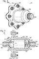
- Check valve assembly 20 generally defines an open configuration, as illustrated in Fig. 5 , in which check valve assembly 20 permits fluid flow from inlet 212 to outlet 222, and a closed configuration, as illustrated in Fig. 4 , in which check valve assembly 20 resists fluid flow between inlet 212 and outlet 222.
- Check valve assembly 20 generally is biased toward the closed configuration by a spring 290 that urges poppet-side sealing surface 116 toward body-side sealing surface 216. Spring 290 also may be referred to herein as a biasing mechanism 290.
- check valve assembly 20 may be configured to resist fluid flow from outlet 222 to inlet 212 and to selectively permit fluid flow from inlet 212 to outlet 222.
- poppet-side sealing surface 116 When check valve assembly 20 is in the closed configuration, poppet-side sealing surface 116 is sealingly engaged with body-side sealing surface 216, whereas when check valve assembly 20 is in the open configuration, poppet-side sealing surface 116 is at least partially disengaged from body-side sealing surface 216 to permit fluid flow from inlet 212 to outlet 222.
- poppet 100 additionally includes an elongate outer skirt 140 having a first skirt end 141, a second skirt end 142, an outer skirt surface 144, and an inner skirt surface 152, such that outer skirt surface 144 and inner skirt surface 152 extend between first skirt end 141 and second skirt end 142.
- Elongate outer skirt 140 is configured to slidingly engage an inner surface 204 of central cavity 202, such as to restrict tilting of poppet 100 with respect to valve body 200.
- elongate outer skirt 140 is configured to retain poppet 100 in an orientation that is coaxial, or at least substantially coaxial, with valve body 200 as check valve assembly 20 transitions between the open configuration and the closed configuration.
- Outer skirt surface 144 may be a cylindrical, or at least substantially cylindrical, outer skirt surface 144.
- inner skirt surface 152 may be a cylindrical, or at least substantially cylindrical, inner skirt surface 152.
- elongate outer skirt 140 may be a hollow cylindrical elongate outer skirt 140, and/or may be coaxial, or at least substantially coaxial, with elongate central core 110. Elongate outer skirt 140 may have any appropriate dimensions relative to elongate central core 110.
- outer core surface 114 of elongate central core 110 may have an outer diameter, an effective outer diameter, or an average effective outer diameter
- inner skirt surface 152 may have an inner diameter, an average inner diameter, or an average effective inner diameter, such that the average outer diameter is at least 20%, at least 30%, at least 40%, at least 50%, at least 60%, at least 70%, at most 90%, at most 80%, at most 70%, at most 60%, and/or at most 50% of the average inner diameter.
- Poppet 100 further includes at least one guide vane 160 radially extending between outer core surface 114 and inner skirt surface 152.
- the at least one guide vane 160 is configured to retain elongate outer skirt 140 in a generally fixed spatial relationship with respect to elongate central core 110 as well as to direct fluid flow through poppet 100 when check valve assembly 20 is in the open configuration.
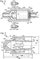
- elongate central core 110 may be a hollow elongate central core 110 and defines a recess 120 that extends from second core end 112 toward first core end 111.
- recess 120 may be configured to reduce a weight of poppet 100 and/or to enhance a fluid flow property through check valve assembly 20.
- Recess 120 may extend any appropriate fraction of a length of elongate central core 110.
- elongate central core 110 has a core length 128 as measured along a longitudinal axis 104 of elongate central core 110, and recess 120 may extend along at least 20%, at least 30%, at least 40%, at least 50%, at least 60%, at least 70%, at least 80%, at least 90%, at most 95%, at most 90%, at most 80%, at most 70%, at most 60%, and/or at most 50% of core length 128.
- recess 120 may extend across any appropriate fraction of a width of elongate central core 110.
- elongate central core 110 defines a first core end thickness 124 as measured along longitudinal axis 104 and between first core end 111 and recess 120 and further defines an average core wall thickness 126 as measured transverse to longitudinal axis 104 and between outer core surface 114 and recess 120.
- First core end thickness 124 may be greater than average core wall thickness 126.
- recess 120 may extend into elongate central core 110 such that a ratio of first core end thickness 124 to average core wall thickness 126 is at least 1.1, at least 1.2, at least 1.4, at least 1.6, at least 1.8, at least 2, at most 5, at most 4, at most 3, at most 2, at most 1.75 and/or at most 1.5. Additionally or alternatively, recess 120 may assume any appropriate shape. For example, recess 120 may be at least partially conical, and/or may be at least partially cylindrical. As a more specific example, in the embodiment illustrated in Fig 9 , recess 120 is generally conical in a region proximal first core end 111 and is generally cylindrical in a region proximal second core end 112.
- elongate central core 110 of poppet 100 additionally includes at least one pressure-relief opening 130 extending from recess 120 and to outer core surface 114.
- Pressure-relief opening 130 generally is sized to decrease a pressure drop across poppet 100 during fluid flow through check valve assembly 20.
- fluid flowing past elongate central core 110 may form a boundary layer adjacent outer core surface 114, which in turn may produce a static pressure gradient in the fluid proximate second core end 112 of elongate central core 110 and/or introduce drag in the fluid flow.
- pressure-relief opening 130 may be configured to bleed the boundary layer of fluid from outside elongate central core 110 so as to re-equalize the fluid static pressure proximate second core end 112, thereby reducing a fluid drag through check valve assembly 20 and/or a pressure drop across check valve assembly 20.
- a flow of fluid through pressure-relief opening 130 may be characterized, for example, by a Fanno model of fluid flow.
- pressure-relief opening 130 provides a path for fluid to flow from external elongate central core 110 into recess 120 during fluid flow through check valve assembly 20, thus decreasing a fluid resistance and/or a fluid drag through check valve assembly 20.
- This additional flow path may particularly decrease a resistance to fluid flow through check valve assembly 20 in a configuration in which spring 290 is significantly compressed.
- spring 290 may act as a barrier against fluid flow from a region external elongate central core 110 to outlet 222, whereas fluid alternatively may flow unimpeded through pressure-relief opening 130 and recess 120 to outlet 222.
- Elongate central core 110 may include a plurality of pressure-relief openings 130 equally and/or circumferentially spaced about longitudinal axis 104. As examples, elongate central core 110 may include at least 2, at least 3, at least 4, at least 5, or at least 6 pressure-relief openings 130.
- Each pressure-relief opening 130 additionally may have any appropriate pressure-relief opening cross-sectional area for fluid flow therethrough.
- the pressure-relief opening cross-sectional area may be at least 1%, at least 5%, at least 10%, at least 15%, at most 25%, at most 20%, at most 15%, and/or at most 10% of an outer core surface area of outer core surface 114.
- each pressure-relief opening 130 may have any appropriate shape.
- a shape of each pressure-relief opening 130 may include and/or be square, rectangular, triangular, circular, elliptical, trapezoidal, quadrilateral, pentagonal, and/or hexagonal.
- Recess 120 may include an etched recess pattern (not illustrated) configured to wick fluid past pressure-relief openings 130 and toward second core end 112.
- the etched recess pattern may include and/or be rectilinear lands, spiral lands, and/or a Bejan Constructal Theory T-network of free distribution of flow.
- poppet 100 is configured to form a fluid seal with valve body 200 via an interface between poppet-side sealing surface 116 and body-side sealing surface 216.
- poppet-side sealing surface 116 may be a machined poppet-side sealing surface 116.
- poppet-side sealing surface 116 may have an average poppet-side sealing surface roughness that is less than a threshold fraction of a poppet surface roughness of a remainder of poppet 100, examples of which include less than 80%, less than 60%, less than 40%, less than 30%, less than 20%, less than 10%, less than 5%, less than 1%, and/or less than 0.1%.
- poppet-side sealing surface 116 may be characterized by a surface roughness that is at most 100 microinch arithmetic mean roughness (mRa), at most 80 mRa, at most 60 mRa, at most 40 mRa, at most 30 mRa, at most 25 mRa, at most 20 mRa, at most 15 mRa, and/or at most 10 mRa.
- mRa microinch arithmetic mean roughness
- poppet 100 includes at least one guide vane 160, which may include and/or be a plurality of guide vanes 160.
- poppet 100 may include a plurality of guide vanes 160 equally and circumferentially spaced about longitudinal axis 104 of elongate central core 110. While Figs. 7-8 illustrate an embodiment of poppet 100 that includes 3 guide vanes 160, this is not required, and it is within the scope of the present disclosure that poppet 100 include any suitable number of guide vanes 160, including at least 2, at least 3, at least 4, at least 5, or at least 6 guide vanes 160.
- the number of guide vanes 160 may be equal to the number of pressure-relief openings 130.
- a corresponding pressure-relief opening 130 may extend between each adjacent pair of guide vanes 160.
- guide vanes 160 of poppet 100 generally are configured to operatively support elongate outer skirt 140 relative to elongate central core 110. Stated differently, guide vanes 160 of poppet 100 are configured to operatively attach elongate central core 110 to elongate outer skirt 140 and hence to retain a fixed, or at least substantially fixed, spatial relationship between elongate central core 110 and elongate outer skirt 140. Guide vanes 160 may be linear or twisted in worm gear geometry. Additionally or alternatively, check valve assembly 20 may include one or more guiderails extending generally between elongate outer skirt 140 and inner surface 204 of valve body 200, and which may have a twist or may be rectilinear in shape.
- guide vanes 160 are shaped to direct fluid flow within an annular region 150 that extends between outer core surface 114 of elongate central core 110 and inner skirt surface 152 of elongate outer skirt 140.
- guide vanes 160 may be shaped to direct fluid flow within annular region 150 in a direction that is parallel, or at least substantially parallel, to longitudinal axis 104 of elongate central core 110.
- each guide vane 160 may have an airfoil-shaped and/or raindrop-shaped cross-sectional profile.
- each guide vane 160 may have a cross-sectional profile that is symmetric about a plane that includes longitudinal axis 104 and that tapers in width from an end of guide vane 160 that is proximal first core end 111 toward an end of guide vane 160 that is proximal second core end 112.
- guide vanes 160 may increase a degree of laminar fluid flow through poppet 100 and/or decrease a degree of turbulent fluid flow through poppet 100 when check valve assembly 20 is in the open configuration. This in turn may decrease a net drag in the fluid flow through poppet 100, thereby decreasing a pressure drop of the fluid across check valve assembly 20 when check valve assembly 20 is in the open configuration.
- guide vanes 160 may be configured to provide flow straightening within check valve assembly 20 and/or to provide a more consistent outlet velocity profile of fluid flowing through outlet 222.
- poppet 100 additionally includes a poppet-side spring seat 132 configured to receive spring 290, which is configured to bias poppet 100 into sealing engagement with valve body 200.
- Poppet-side spring seat 132 may be defined by any appropriate portion of poppet 100, such as second core end 112, second skirt end 142, and/or a region of at least one guide vane 160 that extends between second core end 112 and second skirt end 142. As illustrated in Figs.
- elongate central core 110 additionally may include a projecting region 134 that projects from second core end 112 and that is configured to extend within a central bore 292 of spring 290, such as to retain spring 290 in an orientation that is coaxial, at least substantially coaxial, or rectilinear with elongate central core 110.
- Poppet 100 includes a unitary poppet body 102 that defines elongate central core 110, elongate outer skirt 140, and guide vanes 160. As illustrated in Figs. 1 and 9 , poppet 100 defines a poppet length 108 as measured along longitudinal axis 104 of elongate central core 110 and an outer diameter 106 as measured about a transverse cross-section of elongate outer skirt 140. Poppet 100 may have any appropriate size and/or shape. As examples, a ratio of poppet length 108 to outer diameter 106 may be at least 1.25, at least 1.5, at least 1.75, at least 2, at least 2.25, at least 5, at most 4, at most 3.5, at most 3, at most 2.5, at most 2, and/or at most 1.5.
- poppet length 108 may be at least 4 centimeters (cm), at least 6 cm, at least 8 cm, at least 10 cm, at most 20 cm, at most 15 cm, at most 10 cm, and/or at most 7.5 cm. Such a configuration may restrict poppet 100 from cocking within central cavity 202.
- elongate outer skirt 140 may have any appropriate positional and/or size relationship with elongate central core 110.
- a ratio of core length 128 of elongate central core 110 to a skirt length 148 of elongate outer skirt 140 (as measured along longitudinal axis 104) may be at least 1, at least 1.1, at least 1.2, at least 1.3, at least 1.4, at least 1.5, at most 2, at most 1.8, at most 1.6, at most 1.4, and/or at most 1.2.
- first skirt end 141 of elongate outer skirt 140 may be positioned between first core end 111 and second core end 112 of elongate central core 110 (as measured along longitudinal axis 104). Stated differently, at least a fraction of core length 128 may project from first skirt end 141 along longitudinal axis 104. As examples, the fraction of core length 128 that projects from first skirt end 141 may be at least 5%, at least 10%, at least 15%, at least 20%, at least 25%, at least 30%, at least 35%, at most 50%, at most 45%, at most 40%, at most 35%, at most 30%, and/or at most 25%.
- second skirt end 142 of elongate outer skirt 140 may be positioned between first core end 111 and second core end 112 of elongate central core 110 (as measured along longitudinal axis 104).
- check valve assembly 20 includes valve body 200, spring 290, and poppet 100.
- Valve body 200 includes central cavity 202, inlet 212 to central cavity 202, outlet 222 from central cavity 202, body-side sealing surface 216, and a body-side spring seat 226 within central cavity 202 and proximate outlet 222.
- Poppet 100 is oriented within cavity 202 such that poppet-side sealing surface 116 is proximate body-side sealing surface 216.
- Central cavity 202 may be a cylindrical, or at least substantially cylindrical, central cavity 202. Additionally or alternatively, a shape of central cavity 202 may correspond to a shape of outer skirt surface 144 of elongate outer skirt 140 such that poppet 100 may transition between the closed configuration of Fig. 4 and the open configuration of Fig. 5 .
- spring 290 may be a linear spring 290, in which case check valve assembly 20 may be referred to as a linear spring check valve assembly 20.
- Spring 290 may have any appropriate cross-sectional shape, such as a circular cross-sectional shape, an elliptical cross-sectional shape, a rectangular cross-sectional shape, a triangular cross-sectional shape, a quadrilateral cross-sectional shape, a rhomboid cross-sectional shape, a star-shaped cross-sectional shape, a hollow cross-sectional shape, an airfoil cross-sectional shape, and/or a square cross-sectional shape.
- spring 290 may have a double-helix geometry, a single leaf spring geometry, a double leaf spring geometry, a compressible origami geometry, a compressible fractal truss network of triangular truss structures, and/or any other compressible geometry.
- Body-side spring seat 226 of valve body 200 generally is sized to receive spring 290, such that spring 290 is received within, positioned on, and/or engaged with body-side spring seat 226.
- check valve assembly 20 is configured to resist fluid flow from outlet 222 to inlet 212 and to selectively permit fluid flow from inlet 212 to outlet 222, and generally defines the closed configuration of Fig. 4 and the open configuration of Fig. 5 .
- Check valve assembly 20 generally is biased toward the closed configuration by spring 290, and is configured to transition from the closed configuration to the open configuration responsive to a pressure differential between inlet 212 and outlet 222 being greater than a threshold opening pressure.
- the threshold opening pressure of check valve assembly 20 also may be referred to as a cracking pressure of check valve assembly 20.
- Check valve assembly 20 may be configured to exhibit any appropriate threshold opening pressure, examples of which include at least 5 pounds per square inch (psi) (35 kilopascals [kPa]), at least 10 psi (69 kPa), at least 20 psi (138 kPa), at least 40 psi (276 kPa), at least 60 psi (414 kPa), at least 80 psi (552 kPa), at least 100 psi (690 kPa), at most 110 psi (758 kPa), at most 90 psi (621 kpa), at most 70 psi (483 kPa), at most 50 psi (345 kPa), at most 30 psi (207 kPa), and/or at most 15 psi (103 kPa).
- psi pounds per square inch
- kPa 35 kilopascals [kPa]
- 10 psi 69
- check valve assembly 20 generally is configured to transition from the open configuration to the closed configuration responsive to the pressure differential between inlet 212 and outlet 222 being less than a threshold closing pressure, which generally is less than the threshold opening pressure.
- Check valve assembly 20 additionally may include an internal actuator configured to selectively compress spring 290, such as to vary the threshold opening pressure of check valve assembly 20.
- check valve assembly 20 may be utilized in a spacecraft, and it may be desirable that check valve assembly 20 exhibit different threshold opening pressures in different regimes of flight, such as hypersonic flight, supersonic flight, transonic flight, and/or subsonic flight.
- Valve body 200 may be a unitary valve body 200, or may include a first body half 210 and a second body half 220 as illustrated collectively by Figs. 2-6 .
- first body half 210 may define inlet 212 and second body half 220 may define outlet 222.
- first body half 210 may include a first flange 214 and second body half may include a second flange 224 such that first body half 210 and second body half 220 are configured to be fastened together via first flange 214 and second flange 224 to define central cavity 202.
- first flange 214 and/or second flange 224 may include at least one O-ring groove 230 configured to receive a corresponding O-ring 232 to provide a fluid seal between first flange 214 and second flange 224.
- Inner surface 204 of valve body 200 may include an etched inner surface pattern that may facilitate accumulation of fluid between inner surface 204 and elongate outer skirt 140. Such fluid may function as a lubricant for relative motion between inner surface 204 and elongate outer skirt 140.
- the etched inner surface pattern may include and/or be rectilinear lands, spiral lands, and/or a Bejan Constructal Theory T-network of free distribution of flow.
- first flange 214 and/or second flange 224 may include an undulating cutout 240, such as which may be configured to reduce a weight of check valve assembly 20.
- undulating cutout 240 also may be referred to as an undulating cross-sectional profile 240, a sinusoidal cutout 240, and/or a sinusoidal cross-sectional profile 240.
- First body half 210 and second body half 220 may be bolted together, welded together, brazed together, screwed together, press-fit together, and/or adhered together to define central cavity 202.
- poppet 100 is configured to form a fluid seal with valve body 200 via an interface between poppet-side sealing surface 116 and body-side sealing surface 216.
- body-side sealing surface 216 may be a machined body-side sealing surface 216.
- body-side sealing surface 216 may have an average body-side sealing surface roughness that is less than a threshold fraction of a valve body surface roughness of a remainder of valve body 200, examples of which include less than 80%, less than 60%, less than 40%, less than 30%, less than 20%, less than 10%, less than 5%, less than 1%, and/or less than 0.1%.
- body-side sealing surface 216 may be characterized by a surface roughness that is at most 100 microinch arithmetic mean roughness (mRa), at most 80 mRa, at most 60 mRa, at most 40 mRa, at most 30 mRa, at most 25 mRa, at most 20 mRa, at most 15 mRa, and/or at most 10 mRa.
- mRa microinch arithmetic mean roughness
- check valve assembly 20 may be configured to withstand any appropriate operating pressure.
- check valve assembly 20 may be configured to withstand at least 100 psig (690 kPa), at least 300 psig (2070 kPa), at least 500 psig (3450 kPa), at least 1000 psig (6900 kPa), at least 3000 psig (20700 kPa), at least 5000 psig (34500 kPa), at least 10000 psig (69000 kPa), at least 30000 psig (207000 kPa), at least 50000 psig (345000 kPa), at least 100000 psig (690000 kPa), at most 110000 psig (758000 kPa), at most 70000 psig (483000 kPa), at most 40000 psig (276000 kPa), at most 7000 psig (48300 kPa), at most 4000 psig (27600 kPa), at most 700 psig (4830 psig
- Poppet 100 and valve body 200 may be formed of any appropriate materials.
- poppet 100 and/or valve body 200 may be formed of a stainless steel, titanium, a titanium alloy, aluminum, a plastic, a fluorocarbon, nickel, a nickel alloy, and/or a nickel, chromium, iron alloy.
- poppet 100 may include a functionally graded material (FGM) with a varying coefficient of thermal expansion (CTE); may include polychlorotrifluoroethene (PCTFE), such as to facilitate a cryogenic seal; may include polyetherketoneketone (PEKK), such as for use in heat-intensive applications; and/or may include light-absorbing colors or any other color, such as red, green, pastel red, and/or pastel green.
- FGM functionally graded material
- CTE varying coefficient of thermal expansion
- PCTFE polychlorotrifluoroethene
- PEKK polyetherketoneketone
- poppet 100 and valve body 200 may be formed via any appropriate manufacturing process.
- poppet 100 and/or valve body 200 may be formed, at least in part, and optionally primarily, via an additive manufacturing process.
- poppet 100 and/or valve body 200 may be formed, at least in part, and optionally primarily, via direct metal laser sintering (DMLS), an electron beam melting process, laser freeform manufacturing technology (LFMT), selective laser melting (SLM), fused deposition modeling (FDM), laser puddle deposition (LPD), small puddle deposition (SPD), laser powder bed (LPB), electron beam powder bed (EBPD), indirect powder bed (IPD), laser deposition technology (LDT), laser repair technology (LRT), laser cladding technology (LCT), laser deposition welding (LDW), laser deposition welding with integrated milling (LDWM), selective laser sintering (SLS), direct metal printing (DMP), stereolithography (SLA), and/or any other appropriate additive manufacturing process.
- DMLS direct metal laser sintering
- LFMT laser
- an additive manufacturing process may facilitate the production of a valve body 200 that includes first flange 214, second flange 224, undulating cutout 240, and/or additional chamfered edges or radius-of-curvature fillets, each of which may reduce a total weight and material cost of check valve assembly 20.
- an additive manufacturing process may facilitate the production of a unitary poppet body 102 that includes non-trivial geometrical shapes such as airfoil-shaped guide vanes 160.
- additive manufacturing processes may reduce a time required to produce check valve assembly 20 or a component thereof relative to a traditional subtractive manufacturing process.
- an additive manufacturing process may permit the manufacturing of poppet 100, of first body half 210, of second body half 220, and/or of any other component of check valve assembly 20 as a single unitary piece, and/or may reduce a need for machining and/or subtractive manufacturing.
- It may be desirable to utilize subtractive machining processes in manufacturing surfaces configured to form fluid-tight interfaces, such as poppet-side sealing surface 116, body-side sealing surface 216, first flange 214, second flange 224, and/or a coupling interface between check valve assembly 20 and an external fluid system.
- subtractive machining may represent a relatively small proportion of a total time and/or material expenditure in the production of check valve assembly 20, a use of additive manufacturing processes still may offer significant economies in the production of check valve assembly 20.
- the phrase, "for example,” the phrase, “as an example,” and/or simply the term “example,” when used with reference to one or more components, features, details, structures, embodiments, and/or methods according to the present disclosure, are intended to convey that the described component, feature, detail, structure, embodiment, and/or method is an illustrative, non-exclusive example of components, features, details, structures, embodiments, and/or methods according to the present disclosure.
Landscapes
- Engineering & Computer Science (AREA)
- General Engineering & Computer Science (AREA)
- Mechanical Engineering (AREA)
- Check Valves (AREA)
Claims (13)
- Rückschlagventilanordnung (20) aufweisend:einen Ventilkörper (200);einen Leitschaufel-Ventilkegel (100), wobei der Leitschaufel-Ventilkegel aufweist:einen länglichen Zentralkern (110), der ein erstes Kernende (111), ein zweites Kernende (112) und eine sich zwischen dem ersten Kernende und dem zweiten Kernende erstreckende Kernaußenfläche (114) hat, wobei das erste Kernende eine kegelseitige Dichtungsfläche (116) definiert, die konfiguriert ist, zusammen mit einer entsprechenden körperseitigen Dichtungsfläche (216) des Ventilkörpers (200) der Rückschlagventilanordnung eine Fluiddichtung zu bilden, wobei der längliche Zentralkern (110) eine Aussparung (120) definiert, die sich von dem zweiten Kernende (112) hin zu dem ersten Kernende (111) erstreckt, und der längliche Zentralkern (110) außerdem mindestens eine Druckentlastungsöffnung (130) aufweist, die sich von der Aussparung (120) aus und zu der Kernaußenfläche (114) erstreckt, wobei die mindestens eine Druckentlastungsöffnung bemessen ist, um während eines Fluidflusses durch die Rückschlagventilanordnung (20) einen Druckabfall über den Kegel zu verringern;eine längliche Außenschürze (140) mit einem ersten Schürzenende (141), einem zweiten Schürzenende (142), einer Schürzenaußenfläche (144) und einer Schürzeninnenfläche (152), wobei sich die Schürzenaußenfläche und die Schürzeninnenfläche zwischen dem ersten Schürzenende und dem zweiten Schürzenende erstrecken; undmindestens eine Leitschaufel (160), die sich radial zwischen der Kernaußenfläche (114) und der Schürzeninnenfläche (152) erstreckt, wobei die mindestens eine Leitschaufel (160) konfiguriert ist, die längliche Außenschürze (140) in einer grundsätzlich festen räumlichen Beziehung bezüglich des länglichen Zentralkerns (110) zu halten, wobei die mindestens eine Leitschaufel (160) geformt ist, um einen Fluidfluss innerhalb eines ringförmigen Bereichs (150) zu leiten, der sich zwischen der Kernaußenfläche (114) und der Schürzeninnenfläche (152) erstreckt; wobeidie längliche Außenschürze konfiguriert ist, eine Innenfläche des Ventilkörpers der Rückschlagventilanordnung gleitend zu greifen;dadurch gekennzeichnet, dass der Leitschaufel-Ventilkegel (100) einen einheitlichen Ventilkegelkörper (102) aufweist, der den länglichen Zentralkern (110), die längliche Außenschürze (140) und die mindestens eine Leitschaufel (160) definiert.
- Anordnung nach Anspruch 1, wobei die Aussparung (120) mindestens teilweise zylindrisch ist.
- Anordnung nach einem der Ansprüche 1 bis 2, wobei der längliche Zentralkern (110) eine Kernlänge (128), wie gemessen entlang seiner Längsachse (104), hat und wobei sich die Aussparung (120) entlang mindestens 60% der Kernlänge erstreckt.
- Anordnung nach einem der Ansprüche 1 bis 3, wobei die Schürzeninnenfläche (152) eine zumindest im Wesentlichen zylindrische Schürzeninnenfläche ist.
- Anordnung nach einem der Ansprüche 1 bis 4, wobei die längliche Außenschürze (140) zumindest im Wesentlichen koaxial mit dem länglichen Zentralkern (110) ist, wobei die Kernaußenfläche (114) einen durchschnittlichen Außendurchmesser definiert, wobei die Schürzeninnenfläche (152) einen durchschnittlichen Innendurchmesser definiert, und weiterhin wobei der durchschnittliche Außendurchmesser (106) mindestens 30% und höchstens 80% des durchschnittlichen Innendurchmessers ist.
- Anordnung nach einem der Ansprüche 1 bis 5, wobei der Ventilkegel eine Ventilkegellänge (108), wie gemessen entlang einer Längsachse (104) des länglichen Zentralkerns (110), und einen Außendurchmesser (106), wie gemessen über einen transversalen Querschnitt der länglichen Außenschürze (140), definiert, und wobei ein Verhältnis der Ventilkegellänge zu dem Außendurchmesser mindestens 1,5 ist.
- Anordnung nach einem der Ansprüche 1 bis 6, wobei der längliche Zentralkern (110) eine Kernlänge (128), wie gemessen entlang seiner Längsachse (104) hat, wobei die längliche Außenschürze (140) eine Schürzenlänge (148), wie gemessen entlang der Längsachse (104), hat, und weiterhin wobei ein Verhältnis der Kernlänge zu der Schürzenlänge mindestens 1 und höchstens 2 ist.
- Anordnung nach einem der Ansprüche 1 bis 7, wobei das erste Schürzenende (141) zwischen dem ersten Kernende (111) und dem zweiten Kernende (112), wie gemessen entlang einer Längsachse (104) des länglichen Zentralkerns (110), angeordnet ist.
- Anordnung nach einem der Ansprü- che 1 bis 8, wobei die mindestens eine Leitschaufel (160) geformt ist, um einen Fluidfluss in einer Richtung zu leiten, die zumindest im Wesentlichen parallel zu einer Längsachse (104) des länglichen Zentralkerns (110) ist.
- Anordnung nach einem der Ansprüche 1 bis 9, wobei die mindestens eine Leitschaufel (160) mindestens ein tragflächenförmiges Querschnittprofil und/oder ein tropfenförmiges Querschnittprofil aufweist.
- Anordnung nach einem der Ansprüche 1 bis 10, wobei die mindestens eine Leitschaufel (160) mehrere Leitschaufeln aufweist, die in gleichmäßigem Abstand am Umkreis um eine Längsachse (104) des länglichen Zentralkerns (110) angeordnet sind, und wobei die mehreren Leitschaufeln konfiguriert sind, eine feste räumliche Beziehung zwischen dem länglichen Zentralkern und der länglichen Außenschürze (140) zu halten.
- Anordnung nach einem der Ansprüche 1 bis 11, wobei der Ventilkegel ferner einen kegelseitigen Federsitz (132) aufweist, der konfiguriert ist, eine Feder (290) aufzunehmen, wobei der längliche Zentralkern (110) weiterhin einen vorspringenden Bereich (134) aufweist, der von dem zweiten Kernende (112) vorspringt, und wobei der vorspringende Bereich konfiguriert ist, sich in einer zentralen Bohrung (292) der Feder zu erstrecken.
- Anordnung nach einem der Ansprüche 1 bis 12, wobei die kegelseitige Dichtungsfläche (116) eine maschinell bearbeitete kegelseitige Dichtungsfläche (116) ist, wobei die kegelseitige Dichtungsfläche eine durchschnittliche kegelseitige Dichtungsflächenrauheit hat, und weiterhin wobei die durchschnittliche kegelseitige Dichtungsflächenrauheit eine Rauheit (mRa) von höchsten 80 Mikro-Inch im arithmetischen Mittel ist.
Applications Claiming Priority (1)
| Application Number | Priority Date | Filing Date | Title |
|---|---|---|---|
| US15/249,203 US10323761B2 (en) | 2016-08-26 | 2016-08-26 | Guide vane check valves |
Publications (2)
| Publication Number | Publication Date |
|---|---|
| EP3287676A1 EP3287676A1 (de) | 2018-02-28 |
| EP3287676B1 true EP3287676B1 (de) | 2020-02-26 |
Family
ID=59070514
Family Applications (1)
| Application Number | Title | Priority Date | Filing Date |
|---|---|---|---|
| EP17176278.4A Active EP3287676B1 (de) | 2016-08-26 | 2017-06-15 | Leitschaufelrückschlagventile |
Country Status (2)
| Country | Link |
|---|---|
| US (2) | US10323761B2 (de) |
| EP (1) | EP3287676B1 (de) |
Cited By (1)
| Publication number | Priority date | Publication date | Assignee | Title |
|---|---|---|---|---|
| US11598433B2 (en) | 2018-10-09 | 2023-03-07 | Burckhardt Compression Ag | Poppet valve and method of manufacturing valve components of a poppet valve |
Families Citing this family (2)
| Publication number | Priority date | Publication date | Assignee | Title |
|---|---|---|---|---|
| EP3485215B1 (de) | 2016-07-12 | 2023-06-07 | Alexander Poltorak | System und verfahren zur bewahrung der effizienz eines kühlkörpers |
| TW202218486A (zh) * | 2020-07-15 | 2022-05-01 | 荷蘭商Asml荷蘭公司 | 用於保護在euv源中之流體管線之設備 |
Family Cites Families (28)
| Publication number | Priority date | Publication date | Assignee | Title |
|---|---|---|---|---|
| US3370508A (en) | 1966-01-10 | 1968-02-27 | Joseph A. Iaia | Method for establishing o-ring seal grooves |
| US3457949A (en) * | 1966-08-24 | 1969-07-29 | Albert L Coulter | Check valve |
| US3874541A (en) | 1971-02-24 | 1975-04-01 | Saint Gobain | Bottle stopper |
| US3731905A (en) | 1971-11-03 | 1973-05-08 | Futurecraft Corp | Poppet valve structure having o-ring seat seal |
| US3831951A (en) | 1972-04-26 | 1974-08-27 | Weatherhead Co | Face type o-ring seal groove and method of producing same |
| US4149560A (en) | 1977-04-06 | 1979-04-17 | Berg Allen L | Brake bleeder valve |
| US4270441A (en) | 1978-10-30 | 1981-06-02 | Wilden Pump & Engineering Co. | Pump diaphragm |
| US4385514A (en) | 1981-07-08 | 1983-05-31 | Mcinerney Spring & Wire Company | Pipe assembly tool |
| JPS60119365A (ja) | 1983-11-25 | 1985-06-26 | ウオルブロ コーポレイシヨン | ポンプ用燃料出口弁 |
| US4566485A (en) | 1984-11-19 | 1986-01-28 | Ruhle James L | Free-floating neutrally-buoyant reciprocating pump valve for abrasive fluids |
| US5183075A (en) * | 1986-04-12 | 1993-02-02 | Stein Guenter | Check valve |
| US4739899A (en) | 1986-10-08 | 1988-04-26 | Uop Inc. | O-Ring closure assembly |
| US5041257A (en) * | 1987-09-14 | 1991-08-20 | Robertshaw Controls Company | Expansion device for a refrigeration system, piston therefor and methods of making the same |
| US5271429A (en) * | 1990-06-23 | 1993-12-21 | Filterwerk Mann & Hummel Gmbh | Internal combustion engine lubricating oil filter valve |
| US5097864A (en) * | 1991-04-01 | 1992-03-24 | Great Lakes Feedscrews, Inc. | Adjustable flow poppet valve for injection molding |
| JP2615429B2 (ja) | 1994-09-13 | 1997-05-28 | 工業技術院長 | 3次元立体形状の創成法 |
| US5745834A (en) | 1995-09-19 | 1998-04-28 | Rockwell International Corporation | Free form fabrication of metallic components |
| DE19643749C2 (de) | 1996-10-23 | 1999-10-21 | Draegerwerk Ag | Pneumatische Steueranordnung für ein Beatmungsgerät |
| US5857897A (en) | 1997-09-23 | 1999-01-12 | General Motors Corporation | Method for machining an "O" ring retention groove into a curved surface |
| US6431521B1 (en) * | 2000-09-21 | 2002-08-13 | Claude Ray Jones | Silicon carbide valve disc for nuclear reactors |
| US20030092302A1 (en) | 2001-11-09 | 2003-05-15 | Conway Christopher J. | O-ring removal slot |
| JP4123350B2 (ja) * | 2002-06-28 | 2008-07-23 | 株式会社ニフコ | 逆流防止バルブ |
| US20060026069A1 (en) * | 2004-05-27 | 2006-02-02 | Larry Mazurkiewicz | Methods and apparatus to implement enhanced employment technology frameworks |
| WO2006042164A1 (en) | 2004-10-08 | 2006-04-20 | Tosoh Smd, Inc. | Low leak-o-ring seal |
| US7168446B2 (en) | 2005-05-13 | 2007-01-30 | Air Products And Chemicals, Inc. | High impact discharge valve |
| US20120263822A1 (en) | 2009-04-13 | 2012-10-18 | Husky Injection Molding Systems Ltd | Check valve |
| DE102011120628A1 (de) * | 2011-12-09 | 2013-06-13 | Illinois Tool Works Inc. | Rückschlagventil |
| US10157778B2 (en) | 2016-05-31 | 2018-12-18 | Taiwan Semiconductor Manufacturing Co., Ltd. | Semiconductor structure and manufacturing method thereof |
-
2016
- 2016-08-26 US US15/249,203 patent/US10323761B2/en not_active Expired - Fee Related
-
2017
- 2017-06-15 EP EP17176278.4A patent/EP3287676B1/de active Active
-
2019
- 2019-04-19 US US16/389,790 patent/US10634259B1/en not_active Expired - Fee Related
Non-Patent Citations (1)
| Title |
|---|
| None * |
Cited By (1)
| Publication number | Priority date | Publication date | Assignee | Title |
|---|---|---|---|---|
| US11598433B2 (en) | 2018-10-09 | 2023-03-07 | Burckhardt Compression Ag | Poppet valve and method of manufacturing valve components of a poppet valve |
Also Published As
| Publication number | Publication date |
|---|---|
| US10634259B1 (en) | 2020-04-28 |
| US20180058595A1 (en) | 2018-03-01 |
| US10323761B2 (en) | 2019-06-18 |
| US20200124193A1 (en) | 2020-04-23 |
| EP3287676A1 (de) | 2018-02-28 |
Similar Documents
| Publication | Publication Date | Title |
|---|---|---|
| EP3287676B1 (de) | Leitschaufelrückschlagventile | |
| EP1757850A1 (de) | Flüssigkeitssteuerventil | |
| US3703273A (en) | Low loss innervalve assembly | |
| CA2590017C (en) | Fluid control valve device | |
| EP2831476B1 (de) | Sitzring zur strömungsausrichtung und steuerventil mit dem sitzring zur strömungsausrichtung | |
| EP2236876B1 (de) | Fremdgesteuertes Tellerventil | |
| EP4299959A2 (de) | Fluidströmungsteuerungsvorrichtungen und -systeme sowie verfahren zum strömen von fluiden dadurch | |
| CN202432002U (zh) | 高压差v型调节球阀 | |
| CN109416131B (zh) | 阀组件 | |
| EP2405163B2 (de) | Düsenrückschlagventil | |
| EP2360401B1 (de) | Tellerventil mit linearer Bereichszunahme | |
| CN213512098U (zh) | 流体流动控制设备和用于流体流动控制设备的阀内件 | |
| US10816102B2 (en) | Erosion resistant steam valve | |
| KR101224803B1 (ko) | 일자패턴 나선형 복합유동체 대유량 유동제어장치 밸브 | |
| RU138816U1 (ru) | Задвижка запорно-регулирующая | |
| US11112032B2 (en) | Tapered anti-cavitation cage | |
| CN211010021U (zh) | 轴流式止回阀 | |
| CN109307089B (zh) | 高频快开止回阀 | |
| PL226859B1 (pl) | Zawór wielodrogowy rozdzielajacy ztłoczkiem srubowym | |
| US3653632A (en) | Fluid dynamic profile | |
| KR20220140516A (ko) | 유체 흐름 제어 장치 및 관련 시스템 및 방법 | |
| JP2022504532A (ja) | ポペットバルブおよびポペットバルブのバルブコンポーネントを製造する方法 |
Legal Events
| Date | Code | Title | Description |
|---|---|---|---|
| PUAI | Public reference made under article 153(3) epc to a published international application that has entered the european phase |
Free format text: ORIGINAL CODE: 0009012 |
|
| STAA | Information on the status of an ep patent application or granted ep patent |
Free format text: STATUS: REQUEST FOR EXAMINATION WAS MADE |
|
| 17P | Request for examination filed |
Effective date: 20170615 |
|
| AK | Designated contracting states |
Kind code of ref document: A1 Designated state(s): AL AT BE BG CH CY CZ DE DK EE ES FI FR GB GR HR HU IE IS IT LI LT LU LV MC MK MT NL NO PL PT RO RS SE SI SK SM TR |
|
| AX | Request for extension of the european patent |
Extension state: BA ME |
|
| RBV | Designated contracting states (corrected) |
Designated state(s): AL AT BE BG CH CY CZ DE DK EE ES FI FR GB GR HR HU IE IS IT LI LT LU LV MC MK MT NL NO PL PT RO RS SE SI SK SM TR |
|
| STAA | Information on the status of an ep patent application or granted ep patent |
Free format text: STATUS: EXAMINATION IS IN PROGRESS |
|
| 17Q | First examination report despatched |
Effective date: 20190218 |
|
| REG | Reference to a national code |
Ref country code: DE Ref legal event code: R079 Ref document number: 602017012148 Country of ref document: DE Free format text: PREVIOUS MAIN CLASS: F16K0015020000 Ipc: F16K0017040000 |
|
| RIC1 | Information provided on ipc code assigned before grant |
Ipc: F16K 17/04 20060101AFI20190806BHEP Ipc: F16K 15/02 20060101ALI20190806BHEP |
|
| GRAP | Despatch of communication of intention to grant a patent |
Free format text: ORIGINAL CODE: EPIDOSNIGR1 |
|
| STAA | Information on the status of an ep patent application or granted ep patent |
Free format text: STATUS: GRANT OF PATENT IS INTENDED |
|
| INTG | Intention to grant announced |
Effective date: 20190927 |
|
| GRAS | Grant fee paid |
Free format text: ORIGINAL CODE: EPIDOSNIGR3 |
|
| GRAA | (expected) grant |
Free format text: ORIGINAL CODE: 0009210 |
|
| STAA | Information on the status of an ep patent application or granted ep patent |
Free format text: STATUS: THE PATENT HAS BEEN GRANTED |
|
| AK | Designated contracting states |
Kind code of ref document: B1 Designated state(s): AL AT BE BG CH CY CZ DE DK EE ES FI FR GB GR HR HU IE IS IT LI LT LU LV MC MK MT NL NO PL PT RO RS SE SI SK SM TR |
|
| REG | Reference to a national code |
Ref country code: GB Ref legal event code: FG4D |
|
| REG | Reference to a national code |
Ref country code: CH Ref legal event code: EP |
|
| REG | Reference to a national code |
Ref country code: AT Ref legal event code: REF Ref document number: 1238039 Country of ref document: AT Kind code of ref document: T Effective date: 20200315 |
|
| REG | Reference to a national code |
Ref country code: IE Ref legal event code: FG4D |
|
| REG | Reference to a national code |
Ref country code: DE Ref legal event code: R096 Ref document number: 602017012148 Country of ref document: DE |
|
| PG25 | Lapsed in a contracting state [announced via postgrant information from national office to epo] |
Ref country code: RS Free format text: LAPSE BECAUSE OF FAILURE TO SUBMIT A TRANSLATION OF THE DESCRIPTION OR TO PAY THE FEE WITHIN THE PRESCRIBED TIME-LIMIT Effective date: 20200226 Ref country code: NO Free format text: LAPSE BECAUSE OF FAILURE TO SUBMIT A TRANSLATION OF THE DESCRIPTION OR TO PAY THE FEE WITHIN THE PRESCRIBED TIME-LIMIT Effective date: 20200526 Ref country code: FI Free format text: LAPSE BECAUSE OF FAILURE TO SUBMIT A TRANSLATION OF THE DESCRIPTION OR TO PAY THE FEE WITHIN THE PRESCRIBED TIME-LIMIT Effective date: 20200226 |
|
| REG | Reference to a national code |
Ref country code: NL Ref legal event code: MP Effective date: 20200226 |
|
| REG | Reference to a national code |
Ref country code: LT Ref legal event code: MG4D |
|
| PG25 | Lapsed in a contracting state [announced via postgrant information from national office to epo] |
Ref country code: HR Free format text: LAPSE BECAUSE OF FAILURE TO SUBMIT A TRANSLATION OF THE DESCRIPTION OR TO PAY THE FEE WITHIN THE PRESCRIBED TIME-LIMIT Effective date: 20200226 Ref country code: IS Free format text: LAPSE BECAUSE OF FAILURE TO SUBMIT A TRANSLATION OF THE DESCRIPTION OR TO PAY THE FEE WITHIN THE PRESCRIBED TIME-LIMIT Effective date: 20200626 Ref country code: GR Free format text: LAPSE BECAUSE OF FAILURE TO SUBMIT A TRANSLATION OF THE DESCRIPTION OR TO PAY THE FEE WITHIN THE PRESCRIBED TIME-LIMIT Effective date: 20200527 Ref country code: LV Free format text: LAPSE BECAUSE OF FAILURE TO SUBMIT A TRANSLATION OF THE DESCRIPTION OR TO PAY THE FEE WITHIN THE PRESCRIBED TIME-LIMIT Effective date: 20200226 Ref country code: SE Free format text: LAPSE BECAUSE OF FAILURE TO SUBMIT A TRANSLATION OF THE DESCRIPTION OR TO PAY THE FEE WITHIN THE PRESCRIBED TIME-LIMIT Effective date: 20200226 Ref country code: BG Free format text: LAPSE BECAUSE OF FAILURE TO SUBMIT A TRANSLATION OF THE DESCRIPTION OR TO PAY THE FEE WITHIN THE PRESCRIBED TIME-LIMIT Effective date: 20200526 |
|
| PG25 | Lapsed in a contracting state [announced via postgrant information from national office to epo] |
Ref country code: NL Free format text: LAPSE BECAUSE OF FAILURE TO SUBMIT A TRANSLATION OF THE DESCRIPTION OR TO PAY THE FEE WITHIN THE PRESCRIBED TIME-LIMIT Effective date: 20200226 |
|
| PG25 | Lapsed in a contracting state [announced via postgrant information from national office to epo] |
Ref country code: RO Free format text: LAPSE BECAUSE OF FAILURE TO SUBMIT A TRANSLATION OF THE DESCRIPTION OR TO PAY THE FEE WITHIN THE PRESCRIBED TIME-LIMIT Effective date: 20200226 Ref country code: SK Free format text: LAPSE BECAUSE OF FAILURE TO SUBMIT A TRANSLATION OF THE DESCRIPTION OR TO PAY THE FEE WITHIN THE PRESCRIBED TIME-LIMIT Effective date: 20200226 Ref country code: CZ Free format text: LAPSE BECAUSE OF FAILURE TO SUBMIT A TRANSLATION OF THE DESCRIPTION OR TO PAY THE FEE WITHIN THE PRESCRIBED TIME-LIMIT Effective date: 20200226 Ref country code: LT Free format text: LAPSE BECAUSE OF FAILURE TO SUBMIT A TRANSLATION OF THE DESCRIPTION OR TO PAY THE FEE WITHIN THE PRESCRIBED TIME-LIMIT Effective date: 20200226 Ref country code: PT Free format text: LAPSE BECAUSE OF FAILURE TO SUBMIT A TRANSLATION OF THE DESCRIPTION OR TO PAY THE FEE WITHIN THE PRESCRIBED TIME-LIMIT Effective date: 20200719 Ref country code: ES Free format text: LAPSE BECAUSE OF FAILURE TO SUBMIT A TRANSLATION OF THE DESCRIPTION OR TO PAY THE FEE WITHIN THE PRESCRIBED TIME-LIMIT Effective date: 20200226 Ref country code: EE Free format text: LAPSE BECAUSE OF FAILURE TO SUBMIT A TRANSLATION OF THE DESCRIPTION OR TO PAY THE FEE WITHIN THE PRESCRIBED TIME-LIMIT Effective date: 20200226 Ref country code: SM Free format text: LAPSE BECAUSE OF FAILURE TO SUBMIT A TRANSLATION OF THE DESCRIPTION OR TO PAY THE FEE WITHIN THE PRESCRIBED TIME-LIMIT Effective date: 20200226 Ref country code: DK Free format text: LAPSE BECAUSE OF FAILURE TO SUBMIT A TRANSLATION OF THE DESCRIPTION OR TO PAY THE FEE WITHIN THE PRESCRIBED TIME-LIMIT Effective date: 20200226 |
|
| REG | Reference to a national code |
Ref country code: AT Ref legal event code: MK05 Ref document number: 1238039 Country of ref document: AT Kind code of ref document: T Effective date: 20200226 |
|
| REG | Reference to a national code |
Ref country code: DE Ref legal event code: R097 Ref document number: 602017012148 Country of ref document: DE |
|
| PLBE | No opposition filed within time limit |
Free format text: ORIGINAL CODE: 0009261 |
|
| STAA | Information on the status of an ep patent application or granted ep patent |
Free format text: STATUS: NO OPPOSITION FILED WITHIN TIME LIMIT |
|
| PG25 | Lapsed in a contracting state [announced via postgrant information from national office to epo] |
Ref country code: MC Free format text: LAPSE BECAUSE OF FAILURE TO SUBMIT A TRANSLATION OF THE DESCRIPTION OR TO PAY THE FEE WITHIN THE PRESCRIBED TIME-LIMIT Effective date: 20200226 Ref country code: IT Free format text: LAPSE BECAUSE OF FAILURE TO SUBMIT A TRANSLATION OF THE DESCRIPTION OR TO PAY THE FEE WITHIN THE PRESCRIBED TIME-LIMIT Effective date: 20200226 Ref country code: AT Free format text: LAPSE BECAUSE OF FAILURE TO SUBMIT A TRANSLATION OF THE DESCRIPTION OR TO PAY THE FEE WITHIN THE PRESCRIBED TIME-LIMIT Effective date: 20200226 |
|
| REG | Reference to a national code |
Ref country code: CH Ref legal event code: PL |
|
| 26N | No opposition filed |
Effective date: 20201127 |
|
| PG25 | Lapsed in a contracting state [announced via postgrant information from national office to epo] |
Ref country code: SI Free format text: LAPSE BECAUSE OF FAILURE TO SUBMIT A TRANSLATION OF THE DESCRIPTION OR TO PAY THE FEE WITHIN THE PRESCRIBED TIME-LIMIT Effective date: 20200226 Ref country code: PL Free format text: LAPSE BECAUSE OF FAILURE TO SUBMIT A TRANSLATION OF THE DESCRIPTION OR TO PAY THE FEE WITHIN THE PRESCRIBED TIME-LIMIT Effective date: 20200226 |
|
| PG25 | Lapsed in a contracting state [announced via postgrant information from national office to epo] |
Ref country code: LU Free format text: LAPSE BECAUSE OF NON-PAYMENT OF DUE FEES Effective date: 20200615 |
|
| REG | Reference to a national code |
Ref country code: BE Ref legal event code: MM Effective date: 20200630 |
|
| PG25 | Lapsed in a contracting state [announced via postgrant information from national office to epo] |
Ref country code: CH Free format text: LAPSE BECAUSE OF NON-PAYMENT OF DUE FEES Effective date: 20200630 Ref country code: LI Free format text: LAPSE BECAUSE OF NON-PAYMENT OF DUE FEES Effective date: 20200630 Ref country code: IE Free format text: LAPSE BECAUSE OF NON-PAYMENT OF DUE FEES Effective date: 20200615 |
|
| PG25 | Lapsed in a contracting state [announced via postgrant information from national office to epo] |
Ref country code: BE Free format text: LAPSE BECAUSE OF NON-PAYMENT OF DUE FEES Effective date: 20200630 |
|
| PG25 | Lapsed in a contracting state [announced via postgrant information from national office to epo] |
Ref country code: TR Free format text: LAPSE BECAUSE OF FAILURE TO SUBMIT A TRANSLATION OF THE DESCRIPTION OR TO PAY THE FEE WITHIN THE PRESCRIBED TIME-LIMIT Effective date: 20200226 Ref country code: MT Free format text: LAPSE BECAUSE OF FAILURE TO SUBMIT A TRANSLATION OF THE DESCRIPTION OR TO PAY THE FEE WITHIN THE PRESCRIBED TIME-LIMIT Effective date: 20200226 Ref country code: CY Free format text: LAPSE BECAUSE OF FAILURE TO SUBMIT A TRANSLATION OF THE DESCRIPTION OR TO PAY THE FEE WITHIN THE PRESCRIBED TIME-LIMIT Effective date: 20200226 |
|
| PG25 | Lapsed in a contracting state [announced via postgrant information from national office to epo] |
Ref country code: MK Free format text: LAPSE BECAUSE OF FAILURE TO SUBMIT A TRANSLATION OF THE DESCRIPTION OR TO PAY THE FEE WITHIN THE PRESCRIBED TIME-LIMIT Effective date: 20200226 Ref country code: AL Free format text: LAPSE BECAUSE OF FAILURE TO SUBMIT A TRANSLATION OF THE DESCRIPTION OR TO PAY THE FEE WITHIN THE PRESCRIBED TIME-LIMIT Effective date: 20200226 |
|
| PGFP | Annual fee paid to national office [announced via postgrant information from national office to epo] |
Ref country code: GB Payment date: 20220628 Year of fee payment: 6 |
|
| PGFP | Annual fee paid to national office [announced via postgrant information from national office to epo] |
Ref country code: FR Payment date: 20220627 Year of fee payment: 6 |
|
| PGFP | Annual fee paid to national office [announced via postgrant information from national office to epo] |
Ref country code: DE Payment date: 20220629 Year of fee payment: 6 |
|
| REG | Reference to a national code |
Ref country code: DE Ref legal event code: R119 Ref document number: 602017012148 Country of ref document: DE |
|
| GBPC | Gb: european patent ceased through non-payment of renewal fee |
Effective date: 20230615 |
|
| PG25 | Lapsed in a contracting state [announced via postgrant information from national office to epo] |
Ref country code: DE Free format text: LAPSE BECAUSE OF NON-PAYMENT OF DUE FEES Effective date: 20240103 Ref country code: GB Free format text: LAPSE BECAUSE OF NON-PAYMENT OF DUE FEES Effective date: 20230615 |