EP3287451B1 - Organische moleküle, insbesondere zur verwendung in organischen optoelektronischen vorrichtungen - Google Patents
Organische moleküle, insbesondere zur verwendung in organischen optoelektronischen vorrichtungen Download PDFInfo
- Publication number
- EP3287451B1 EP3287451B1 EP17187665.9A EP17187665A EP3287451B1 EP 3287451 B1 EP3287451 B1 EP 3287451B1 EP 17187665 A EP17187665 A EP 17187665A EP 3287451 B1 EP3287451 B1 EP 3287451B1
- Authority
- EP
- European Patent Office
- Prior art keywords
- group
- atoms
- substituted
- radicals
- case
- Prior art date
- Legal status (The legal status is an assumption and is not a legal conclusion. Google has not performed a legal analysis and makes no representation as to the accuracy of the status listed.)
- Active
Links
- 230000005693 optoelectronics Effects 0.000 title claims description 27
- -1 2-substituted 4-pyridineboronic acid Chemical class 0.000 claims description 72
- 229910052799 carbon Inorganic materials 0.000 claims description 54
- 239000000463 material Substances 0.000 claims description 53
- 125000003118 aryl group Chemical group 0.000 claims description 51
- 238000006243 chemical reaction Methods 0.000 claims description 49
- YZCKVEUIGOORGS-OUBTZVSYSA-N Deuterium Chemical compound [2H] YZCKVEUIGOORGS-OUBTZVSYSA-N 0.000 claims description 37
- 229910052805 deuterium Inorganic materials 0.000 claims description 37
- 229910052760 oxygen Inorganic materials 0.000 claims description 37
- 229910052717 sulfur Inorganic materials 0.000 claims description 36
- 125000004432 carbon atom Chemical group C* 0.000 claims description 32
- 125000003342 alkenyl group Chemical group 0.000 claims description 26
- 239000000126 substance Substances 0.000 claims description 24
- 125000000304 alkynyl group Chemical group 0.000 claims description 23
- 125000004435 hydrogen atom Chemical group [H]* 0.000 claims description 22
- 125000003545 alkoxy group Chemical group 0.000 claims description 19
- 125000000217 alkyl group Chemical group 0.000 claims description 18
- 239000000203 mixture Substances 0.000 claims description 18
- 229910052710 silicon Inorganic materials 0.000 claims description 18
- 125000005309 thioalkoxy group Chemical group 0.000 claims description 18
- 239000000758 substrate Substances 0.000 claims description 15
- 125000006165 cyclic alkyl group Chemical group 0.000 claims description 11
- 229910052739 hydrogen Inorganic materials 0.000 claims description 11
- 238000002347 injection Methods 0.000 claims description 11
- 239000007924 injection Substances 0.000 claims description 11
- 239000000243 solution Substances 0.000 claims description 11
- 125000004104 aryloxy group Chemical group 0.000 claims description 9
- 125000004986 diarylamino group Chemical group 0.000 claims description 9
- 125000005240 diheteroarylamino group Chemical group 0.000 claims description 9
- 125000005553 heteroaryloxy group Chemical group 0.000 claims description 9
- 238000000034 method Methods 0.000 claims description 9
- 239000002904 solvent Substances 0.000 claims description 8
- 238000004519 manufacturing process Methods 0.000 claims description 7
- 125000004122 cyclic group Chemical group 0.000 claims description 6
- 239000007789 gas Substances 0.000 claims description 6
- XSXHWVKGUXMUQE-UHFFFAOYSA-N osmium dioxide Inorganic materials O=[Os]=O XSXHWVKGUXMUQE-UHFFFAOYSA-N 0.000 claims description 6
- 125000001997 phenyl group Chemical group [H]C1=C([H])C([H])=C(*)C([H])=C1[H] 0.000 claims description 5
- 125000000609 carbazolyl group Chemical group C1(=CC=CC=2C3=CC=CC=C3NC12)* 0.000 claims description 4
- 230000005669 field effect Effects 0.000 claims description 4
- 125000002496 methyl group Chemical group [H]C([H])([H])* 0.000 claims description 4
- 125000002950 monocyclic group Chemical group 0.000 claims description 3
- 125000003367 polycyclic group Chemical group 0.000 claims description 3
- 125000004076 pyridyl group Chemical group 0.000 claims description 3
- 125000000714 pyrimidinyl group Chemical group 0.000 claims description 3
- 125000004306 triazinyl group Chemical group 0.000 claims description 3
- 125000001931 aliphatic group Chemical group 0.000 claims description 2
- 239000000975 dye Substances 0.000 claims description 2
- 238000012545 processing Methods 0.000 claims description 2
- 239000000376 reactant Substances 0.000 claims description 2
- 238000001771 vacuum deposition Methods 0.000 claims description 2
- 229910052720 vanadium Inorganic materials 0.000 claims description 2
- 229920003229 poly(methyl methacrylate) Polymers 0.000 description 136
- 239000004926 polymethyl methacrylate Substances 0.000 description 136
- 239000010410 layer Substances 0.000 description 120
- 238000000295 emission spectrum Methods 0.000 description 92
- 238000006862 quantum yield reaction Methods 0.000 description 52
- 238000005424 photoluminescence Methods 0.000 description 49
- 241001164823 Adeno-associated virus - 7 Species 0.000 description 46
- 241001655883 Adeno-associated virus - 1 Species 0.000 description 42
- 150000003254 radicals Chemical group 0.000 description 26
- XEKOWRVHYACXOJ-UHFFFAOYSA-N Ethyl acetate Chemical compound CCOC(C)=O XEKOWRVHYACXOJ-UHFFFAOYSA-N 0.000 description 24
- 150000005829 chemical entities Chemical class 0.000 description 17
- 238000000589 high-performance liquid chromatography-mass spectrometry Methods 0.000 description 16
- QLULGIRFKAWHOJ-UHFFFAOYSA-N pyridin-4-ylboronic acid Chemical group OB(O)C1=CC=NC=C1 QLULGIRFKAWHOJ-UHFFFAOYSA-N 0.000 description 15
- 0 *c1c(*=C)c(*=C)c(c(c(*#C)c(c(I)c2*=C)*#C)c2[n]2*)c2c1*=C Chemical compound *c1c(*=C)c(*=C)c(c(c(*#C)c(c(I)c2*=C)*#C)c2[n]2*)c2c1*=C 0.000 description 14
- AWXGSYPUMWKTBR-UHFFFAOYSA-N 4-carbazol-9-yl-n,n-bis(4-carbazol-9-ylphenyl)aniline Chemical compound C12=CC=CC=C2C2=CC=CC=C2N1C1=CC=C(N(C=2C=CC(=CC=2)N2C3=CC=CC=C3C3=CC=CC=C32)C=2C=CC(=CC=2)N2C3=CC=CC=C3C3=CC=CC=C32)C=C1 AWXGSYPUMWKTBR-UHFFFAOYSA-N 0.000 description 14
- 230000014759 maintenance of location Effects 0.000 description 14
- MMNNWKCYXNXWBG-UHFFFAOYSA-N 2,4,6-tris(3-phenylphenyl)-1,3,5-triazine Chemical compound C1=CC=CC=C1C1=CC=CC(C=2N=C(N=C(N=2)C=2C=C(C=CC=2)C=2C=CC=CC=2)C=2C=C(C=CC=2)C=2C=CC=CC=2)=C1 MMNNWKCYXNXWBG-UHFFFAOYSA-N 0.000 description 13
- XESMNQMWRSEIET-UHFFFAOYSA-N 2,9-dinaphthalen-2-yl-4,7-diphenyl-1,10-phenanthroline Chemical compound C1=CC=CC=C1C1=CC(C=2C=C3C=CC=CC3=CC=2)=NC2=C1C=CC1=C(C=3C=CC=CC=3)C=C(C=3C=C4C=CC=CC4=CC=3)N=C21 XESMNQMWRSEIET-UHFFFAOYSA-N 0.000 description 13
- 101000837344 Homo sapiens T-cell leukemia translocation-altered gene protein Proteins 0.000 description 13
- 102100028692 T-cell leukemia translocation-altered gene protein Human genes 0.000 description 13
- 230000015572 biosynthetic process Effects 0.000 description 13
- 239000011521 glass Substances 0.000 description 12
- HXITXNWTGFUOAU-UHFFFAOYSA-N phenylboronic acid Chemical compound OB(O)C1=CC=CC=C1 HXITXNWTGFUOAU-UHFFFAOYSA-N 0.000 description 12
- 238000003786 synthesis reaction Methods 0.000 description 12
- UHOVQNZJYSORNB-UHFFFAOYSA-N Benzene Chemical compound C1=CC=CC=C1 UHOVQNZJYSORNB-UHFFFAOYSA-N 0.000 description 11
- 230000000903 blocking effect Effects 0.000 description 10
- 150000002148 esters Chemical class 0.000 description 10
- 125000002023 trifluoromethyl group Chemical group FC(F)(F)* 0.000 description 10
- XLYOFNOQVPJJNP-UHFFFAOYSA-N water Substances O XLYOFNOQVPJJNP-UHFFFAOYSA-N 0.000 description 10
- BNBRIFIJRKJGEI-UHFFFAOYSA-N 2,6-difluorobenzonitrile Chemical compound FC1=CC=CC(F)=C1C#N BNBRIFIJRKJGEI-UHFFFAOYSA-N 0.000 description 9
- WHMHUGLMCAFKFE-UHFFFAOYSA-N 9-[3,5-di(dibenzofuran-2-yl)phenyl]carbazole Chemical compound C1=CC=C2C3=CC(C=4C=C(C=C(C=4)N4C5=CC=CC=C5C5=CC=CC=C54)C4=CC=C5OC=6C(C5=C4)=CC=CC=6)=CC=C3OC2=C1 WHMHUGLMCAFKFE-UHFFFAOYSA-N 0.000 description 9
- YXFVVABEGXRONW-UHFFFAOYSA-N Toluene Chemical compound CC1=CC=CC=C1 YXFVVABEGXRONW-UHFFFAOYSA-N 0.000 description 9
- 229910052757 nitrogen Inorganic materials 0.000 description 9
- 241000580270 Adeno-associated virus - 4 Species 0.000 description 8
- UJOBWOGCFQCDNV-UHFFFAOYSA-N 9H-carbazole Chemical compound C1=CC=C2C3=CC=CC=C3NC2=C1 UJOBWOGCFQCDNV-UHFFFAOYSA-N 0.000 description 7
- XDTMQSROBMDMFD-UHFFFAOYSA-N Cyclohexane Chemical compound C1CCCCC1 XDTMQSROBMDMFD-UHFFFAOYSA-N 0.000 description 7
- 125000001072 heteroaryl group Chemical group 0.000 description 7
- IJGRMHOSHXDMSA-UHFFFAOYSA-N nitrogen Substances N#N IJGRMHOSHXDMSA-UHFFFAOYSA-N 0.000 description 7
- UFYBTLOLWSABAU-UHFFFAOYSA-N (2-methylpyridin-4-yl)boronic acid Chemical compound CC1=CC(B(O)O)=CC=N1 UFYBTLOLWSABAU-UHFFFAOYSA-N 0.000 description 6
- RYHBNJHYFVUHQT-UHFFFAOYSA-N 1,4-Dioxane Chemical compound C1COCCO1 RYHBNJHYFVUHQT-UHFFFAOYSA-N 0.000 description 6
- NGSKFMPSBUAUNE-UHFFFAOYSA-N 2,6-dichloro-4-iodopyridine Chemical compound ClC1=CC(I)=CC(Cl)=N1 NGSKFMPSBUAUNE-UHFFFAOYSA-N 0.000 description 6
- YMWUJEATGCHHMB-UHFFFAOYSA-N Dichloromethane Chemical compound ClCCl YMWUJEATGCHHMB-UHFFFAOYSA-N 0.000 description 6
- IAZDPXIOMUYVGZ-UHFFFAOYSA-N Dimethylsulphoxide Chemical compound CS(C)=O IAZDPXIOMUYVGZ-UHFFFAOYSA-N 0.000 description 6
- LFQSCWFLJHTTHZ-UHFFFAOYSA-N Ethanol Chemical compound CCO LFQSCWFLJHTTHZ-UHFFFAOYSA-N 0.000 description 6
- 230000035484 reaction time Effects 0.000 description 6
- WEVYAHXRMPXWCK-UHFFFAOYSA-N Acetonitrile Chemical compound CC#N WEVYAHXRMPXWCK-UHFFFAOYSA-N 0.000 description 5
- JUJWROOIHBZHMG-UHFFFAOYSA-N Pyridine Chemical compound C1=CC=NC=C1 JUJWROOIHBZHMG-UHFFFAOYSA-N 0.000 description 5
- 238000004770 highest occupied molecular orbital Methods 0.000 description 5
- 238000004768 lowest unoccupied molecular orbital Methods 0.000 description 5
- 238000001161 time-correlated single photon counting Methods 0.000 description 5
- VTRFAYHJKSKHGY-UHFFFAOYSA-N 4-bromo-2,6-dimethylpyridine Chemical compound CC1=CC(Br)=CC(C)=N1 VTRFAYHJKSKHGY-UHFFFAOYSA-N 0.000 description 4
- YEWVLWWLYHXZLZ-UHFFFAOYSA-N 9-(3-dibenzofuran-2-ylphenyl)carbazole Chemical compound C1=CC=C2C3=CC(C=4C=CC=C(C=4)N4C5=CC=CC=C5C5=CC=CC=C54)=CC=C3OC2=C1 YEWVLWWLYHXZLZ-UHFFFAOYSA-N 0.000 description 4
- VFUDMQLBKNMONU-UHFFFAOYSA-N 9-[4-(4-carbazol-9-ylphenyl)phenyl]carbazole Chemical compound C12=CC=CC=C2C2=CC=CC=C2N1C1=CC=C(C=2C=CC(=CC=2)N2C3=CC=CC=C3C3=CC=CC=C32)C=C1 VFUDMQLBKNMONU-UHFFFAOYSA-N 0.000 description 4
- CSNNHWWHGAXBCP-UHFFFAOYSA-L Magnesium sulfate Chemical compound [Mg+2].[O-][S+2]([O-])([O-])[O-] CSNNHWWHGAXBCP-UHFFFAOYSA-L 0.000 description 4
- ZMXDDKWLCZADIW-UHFFFAOYSA-N N,N-Dimethylformamide Chemical compound CN(C)C=O ZMXDDKWLCZADIW-UHFFFAOYSA-N 0.000 description 4
- SMWDFEZZVXVKRB-UHFFFAOYSA-N Quinoline Chemical compound N1=CC=CC2=CC=CC=C21 SMWDFEZZVXVKRB-UHFFFAOYSA-N 0.000 description 4
- FAPWRFPIFSIZLT-UHFFFAOYSA-M Sodium chloride Chemical class [Na+].[Cl-] FAPWRFPIFSIZLT-UHFFFAOYSA-M 0.000 description 4
- WYURNTSHIVDZCO-UHFFFAOYSA-N Tetrahydrofuran Chemical compound C1CCOC1 WYURNTSHIVDZCO-UHFFFAOYSA-N 0.000 description 4
- YTPLMLYBLZKORZ-UHFFFAOYSA-N Thiophene Chemical compound C=1C=CSC=1 YTPLMLYBLZKORZ-UHFFFAOYSA-N 0.000 description 4
- 239000007983 Tris buffer Substances 0.000 description 4
- XLOMVQKBTHCTTD-UHFFFAOYSA-N Zinc monoxide Chemical compound [Zn]=O XLOMVQKBTHCTTD-UHFFFAOYSA-N 0.000 description 4
- MWPLVEDNUUSJAV-UHFFFAOYSA-N anthracene Chemical compound C1=CC=CC2=CC3=CC=CC=C3C=C21 MWPLVEDNUUSJAV-UHFFFAOYSA-N 0.000 description 4
- 150000001716 carbazoles Chemical class 0.000 description 4
- 239000012876 carrier material Substances 0.000 description 4
- 238000000576 coating method Methods 0.000 description 4
- 230000000052 comparative effect Effects 0.000 description 4
- DKHNGUNXLDCATP-UHFFFAOYSA-N dipyrazino[2,3-f:2',3'-h]quinoxaline-2,3,6,7,10,11-hexacarbonitrile Chemical compound C12=NC(C#N)=C(C#N)N=C2C2=NC(C#N)=C(C#N)N=C2C2=C1N=C(C#N)C(C#N)=N2 DKHNGUNXLDCATP-UHFFFAOYSA-N 0.000 description 4
- 238000005538 encapsulation Methods 0.000 description 4
- 230000005525 hole transport Effects 0.000 description 4
- AWJUIBRHMBBTKR-UHFFFAOYSA-N isoquinoline Chemical compound C1=NC=CC2=CC=CC=C21 AWJUIBRHMBBTKR-UHFFFAOYSA-N 0.000 description 4
- 239000011159 matrix material Substances 0.000 description 4
- 238000005259 measurement Methods 0.000 description 4
- YNPNZTXNASCQKK-UHFFFAOYSA-N phenanthrene Chemical compound C1=CC=C2C3=CC=CC=C3C=CC2=C1 YNPNZTXNASCQKK-UHFFFAOYSA-N 0.000 description 4
- 239000000047 product Substances 0.000 description 4
- 230000003595 spectral effect Effects 0.000 description 4
- LWIHDJKSTIGBAC-UHFFFAOYSA-K tripotassium phosphate Chemical compound [K+].[K+].[K+].[O-]P([O-])([O-])=O LWIHDJKSTIGBAC-UHFFFAOYSA-K 0.000 description 4
- TXBFHHYSJNVGBX-UHFFFAOYSA-N (4-diphenylphosphorylphenyl)-triphenylsilane Chemical compound C=1C=CC=CC=1P(C=1C=CC(=CC=1)[Si](C=1C=CC=CC=1)(C=1C=CC=CC=1)C=1C=CC=CC=1)(=O)C1=CC=CC=C1 TXBFHHYSJNVGBX-UHFFFAOYSA-N 0.000 description 3
- XOYZGLGJSAZOAG-UHFFFAOYSA-N 1-n,1-n,4-n-triphenyl-4-n-[4-[4-(n-[4-(n-phenylanilino)phenyl]anilino)phenyl]phenyl]benzene-1,4-diamine Chemical compound C1=CC=CC=C1N(C=1C=CC(=CC=1)N(C=1C=CC=CC=1)C=1C=CC(=CC=1)C=1C=CC(=CC=1)N(C=1C=CC=CC=1)C=1C=CC(=CC=1)N(C=1C=CC=CC=1)C=1C=CC=CC=1)C1=CC=CC=C1 XOYZGLGJSAZOAG-UHFFFAOYSA-N 0.000 description 3
- SPDPTFAJSFKAMT-UHFFFAOYSA-N 1-n-[4-[4-(n-[4-(3-methyl-n-(3-methylphenyl)anilino)phenyl]anilino)phenyl]phenyl]-4-n,4-n-bis(3-methylphenyl)-1-n-phenylbenzene-1,4-diamine Chemical compound CC1=CC=CC(N(C=2C=CC(=CC=2)N(C=2C=CC=CC=2)C=2C=CC(=CC=2)C=2C=CC(=CC=2)N(C=2C=CC=CC=2)C=2C=CC(=CC=2)N(C=2C=C(C)C=CC=2)C=2C=C(C)C=CC=2)C=2C=C(C)C=CC=2)=C1 SPDPTFAJSFKAMT-UHFFFAOYSA-N 0.000 description 3
- MQRCTQVBZYBPQE-UHFFFAOYSA-N 189363-47-1 Chemical compound C1=CC=CC=C1N(C=1C=C2C3(C4=CC(=CC=C4C2=CC=1)N(C=1C=CC=CC=1)C=1C=CC=CC=1)C1=CC(=CC=C1C1=CC=C(C=C13)N(C=1C=CC=CC=1)C=1C=CC=CC=1)N(C=1C=CC=CC=1)C=1C=CC=CC=1)C1=CC=CC=C1 MQRCTQVBZYBPQE-UHFFFAOYSA-N 0.000 description 3
- YHOIAMUAYXTORN-UHFFFAOYSA-N 2-bromo-4,5-difluorobenzonitrile Chemical compound FC1=CC(Br)=C(C#N)C=C1F YHOIAMUAYXTORN-UHFFFAOYSA-N 0.000 description 3
- PWJYOTPKLOICJK-UHFFFAOYSA-N 2-methyl-9h-carbazole Chemical compound C1=CC=C2C3=CC=C(C)C=C3NC2=C1 PWJYOTPKLOICJK-UHFFFAOYSA-N 0.000 description 3
- ZLHINBZEEMIWIR-UHFFFAOYSA-N 9-(3-dibenzothiophen-2-ylphenyl)carbazole Chemical compound C1=CC=C2C3=CC(C=4C=CC=C(C=4)N4C5=CC=CC=C5C5=CC=CC=C54)=CC=C3SC2=C1 ZLHINBZEEMIWIR-UHFFFAOYSA-N 0.000 description 3
- 229920001621 AMOLED Polymers 0.000 description 3
- YLQBMQCUIZJEEH-UHFFFAOYSA-N Furan Chemical compound C=1C=COC=1 YLQBMQCUIZJEEH-UHFFFAOYSA-N 0.000 description 3
- 229920000144 PEDOT:PSS Polymers 0.000 description 3
- 125000006193 alkinyl group Chemical group 0.000 description 3
- 125000003636 chemical group Chemical group 0.000 description 3
- 229960001760 dimethyl sulfoxide Drugs 0.000 description 3
- 239000002019 doping agent Substances 0.000 description 3
- 230000005284 excitation Effects 0.000 description 3
- GVEPBJHOBDJJJI-UHFFFAOYSA-N fluoranthrene Natural products C1=CC(C2=CC=CC=C22)=C3C2=CC=CC3=C1 GVEPBJHOBDJJJI-UHFFFAOYSA-N 0.000 description 3
- 125000005842 heteroatom Chemical group 0.000 description 3
- RAXXELZNTBOGNW-UHFFFAOYSA-N imidazole Natural products C1=CNC=N1 RAXXELZNTBOGNW-UHFFFAOYSA-N 0.000 description 3
- 229910052751 metal Inorganic materials 0.000 description 3
- 239000002184 metal Substances 0.000 description 3
- 238000002360 preparation method Methods 0.000 description 3
- 239000007787 solid Substances 0.000 description 3
- FCEHBMOGCRZNNI-UHFFFAOYSA-N 1-benzothiophene Chemical compound C1=CC=C2SC=CC2=C1 FCEHBMOGCRZNNI-UHFFFAOYSA-N 0.000 description 2
- ATTVYRDSOVWELU-UHFFFAOYSA-N 1-diphenylphosphoryl-2-(2-diphenylphosphorylphenoxy)benzene Chemical compound C=1C=CC=CC=1P(C=1C(=CC=CC=1)OC=1C(=CC=CC=1)P(=O)(C=1C=CC=CC=1)C=1C=CC=CC=1)(=O)C1=CC=CC=C1 ATTVYRDSOVWELU-UHFFFAOYSA-N 0.000 description 2
- GKWLILHTTGWKLQ-UHFFFAOYSA-N 2,3-dihydrothieno[3,4-b][1,4]dioxine Chemical compound O1CCOC2=CSC=C21 GKWLILHTTGWKLQ-UHFFFAOYSA-N 0.000 description 2
- STTGYIUESPWXOW-UHFFFAOYSA-N 2,9-dimethyl-4,7-diphenyl-1,10-phenanthroline Chemical compound C=12C=CC3=C(C=4C=CC=CC=4)C=C(C)N=C3C2=NC(C)=CC=1C1=CC=CC=C1 STTGYIUESPWXOW-UHFFFAOYSA-N 0.000 description 2
- IXHWGNYCZPISET-UHFFFAOYSA-N 2-[4-(dicyanomethylidene)-2,3,5,6-tetrafluorocyclohexa-2,5-dien-1-ylidene]propanedinitrile Chemical compound FC1=C(F)C(=C(C#N)C#N)C(F)=C(F)C1=C(C#N)C#N IXHWGNYCZPISET-UHFFFAOYSA-N 0.000 description 2
- FIHILUSWISKVSR-UHFFFAOYSA-N 3,6-dibromo-9h-carbazole Chemical compound C1=C(Br)C=C2C3=CC(Br)=CC=C3NC2=C1 FIHILUSWISKVSR-UHFFFAOYSA-N 0.000 description 2
- IORVOBJVFPHSKR-UHFFFAOYSA-N 3-bromo-2,6-difluorobenzonitrile Chemical compound FC1=CC=C(Br)C(F)=C1C#N IORVOBJVFPHSKR-UHFFFAOYSA-N 0.000 description 2
- PHKYYUQQYARDIU-UHFFFAOYSA-N 3-methyl-9h-carbazole Chemical compound C1=CC=C2C3=CC(C)=CC=C3NC2=C1 PHKYYUQQYARDIU-UHFFFAOYSA-N 0.000 description 2
- WPUSEOSICYGUEW-UHFFFAOYSA-N 4-[4-(4-methoxy-n-(4-methoxyphenyl)anilino)phenyl]-n,n-bis(4-methoxyphenyl)aniline Chemical compound C1=CC(OC)=CC=C1N(C=1C=CC(=CC=1)C=1C=CC(=CC=1)N(C=1C=CC(OC)=CC=1)C=1C=CC(OC)=CC=1)C1=CC=C(OC)C=C1 WPUSEOSICYGUEW-UHFFFAOYSA-N 0.000 description 2
- YIEQHIRFLYNDKP-UHFFFAOYSA-N 4-bromo-2,5-difluorobenzonitrile Chemical compound FC1=CC(C#N)=C(F)C=C1Br YIEQHIRFLYNDKP-UHFFFAOYSA-N 0.000 description 2
- TZHQWUAOIWRFSW-UHFFFAOYSA-N 4-bromo-2,6-difluorobenzonitrile Chemical compound FC1=CC(Br)=CC(F)=C1C#N TZHQWUAOIWRFSW-UHFFFAOYSA-N 0.000 description 2
- LRMUGJVHRUVMHP-UHFFFAOYSA-N 4-bromo-3,5-difluorobenzonitrile Chemical compound FC1=CC(C#N)=CC(F)=C1Br LRMUGJVHRUVMHP-UHFFFAOYSA-N 0.000 description 2
- LGDCSNDMFFFSHY-UHFFFAOYSA-N 4-butyl-n,n-diphenylaniline Chemical compound C1=CC(CCCC)=CC=C1N(C=1C=CC=CC=1)C1=CC=CC=C1 LGDCSNDMFFFSHY-UHFFFAOYSA-N 0.000 description 2
- XYDFQQZOWRUBEK-UHFFFAOYSA-N 4-chloro-3-phenylpyridine Chemical compound ClC1=CC=NC=C1C1=CC=CC=C1 XYDFQQZOWRUBEK-UHFFFAOYSA-N 0.000 description 2
- ZOKIJILZFXPFTO-UHFFFAOYSA-N 4-methyl-n-[4-[1-[4-(4-methyl-n-(4-methylphenyl)anilino)phenyl]cyclohexyl]phenyl]-n-(4-methylphenyl)aniline Chemical compound C1=CC(C)=CC=C1N(C=1C=CC(=CC=1)C1(CCCCC1)C=1C=CC(=CC=1)N(C=1C=CC(C)=CC=1)C=1C=CC(C)=CC=1)C1=CC=C(C)C=C1 ZOKIJILZFXPFTO-UHFFFAOYSA-N 0.000 description 2
- MMCIFQUWYTZTIW-UHFFFAOYSA-N 5-bromo-2,3-difluorobenzonitrile Chemical compound FC1=CC(Br)=CC(C#N)=C1F MMCIFQUWYTZTIW-UHFFFAOYSA-N 0.000 description 2
- KDCGOANMDULRCW-UHFFFAOYSA-N 7H-purine Chemical compound N1=CNC2=NC=NC2=C1 KDCGOANMDULRCW-UHFFFAOYSA-N 0.000 description 2
- XVBYZOSXOUDFKJ-UHFFFAOYSA-N 9-[3,5-di(dibenzothiophen-2-yl)phenyl]carbazole Chemical compound C1=C(C=CC=2SC3=C(C=21)C=CC=C3)C=1C=C(C=C(C=1)C1=CC2=C(SC3=C2C=CC=C3)C=C1)N1C2=CC=CC=C2C=2C=CC=CC1=2 XVBYZOSXOUDFKJ-UHFFFAOYSA-N 0.000 description 2
- FXKMXDQBHDTQII-UHFFFAOYSA-N 9-phenyl-3,6-bis(9-phenylcarbazol-3-yl)carbazole Chemical compound C1=CC=CC=C1N1C2=CC=C(C=3C=C4C5=CC(=CC=C5N(C=5C=CC=CC=5)C4=CC=3)C=3C=C4C5=CC=CC=C5N(C=5C=CC=CC=5)C4=CC=3)C=C2C2=CC=CC=C21 FXKMXDQBHDTQII-UHFFFAOYSA-N 0.000 description 2
- CSCPPACGZOOCGX-UHFFFAOYSA-N Acetone Chemical compound CC(C)=O CSCPPACGZOOCGX-UHFFFAOYSA-N 0.000 description 2
- 241000202702 Adeno-associated virus - 3 Species 0.000 description 2
- 241001634120 Adeno-associated virus - 5 Species 0.000 description 2
- SIKJAQJRHWYJAI-UHFFFAOYSA-N Indole Chemical compound C1=CC=C2NC=CC2=C1 SIKJAQJRHWYJAI-UHFFFAOYSA-N 0.000 description 2
- CPLXHLVBOLITMK-UHFFFAOYSA-N Magnesium oxide Chemical compound [Mg]=O CPLXHLVBOLITMK-UHFFFAOYSA-N 0.000 description 2
- UFWIBTONFRDIAS-UHFFFAOYSA-N Naphthalene Chemical compound C1=CC=CC2=CC=CC=C21 UFWIBTONFRDIAS-UHFFFAOYSA-N 0.000 description 2
- PCNDJXKNXGMECE-UHFFFAOYSA-N Phenazine Natural products C1=CC=CC2=NC3=CC=CC=C3N=C21 PCNDJXKNXGMECE-UHFFFAOYSA-N 0.000 description 2
- 229920001609 Poly(3,4-ethylenedioxythiophene) Polymers 0.000 description 2
- KYQCOXFCLRTKLS-UHFFFAOYSA-N Pyrazine Chemical compound C1=CN=CC=N1 KYQCOXFCLRTKLS-UHFFFAOYSA-N 0.000 description 2
- CZPWVGJYEJSRLH-UHFFFAOYSA-N Pyrimidine Chemical compound C1=CN=CN=C1 CZPWVGJYEJSRLH-UHFFFAOYSA-N 0.000 description 2
- KAESVJOAVNADME-UHFFFAOYSA-N Pyrrole Chemical compound C=1C=CNC=1 KAESVJOAVNADME-UHFFFAOYSA-N 0.000 description 2
- GWEVSGVZZGPLCZ-UHFFFAOYSA-N Titan oxide Chemical compound O=[Ti]=O GWEVSGVZZGPLCZ-UHFFFAOYSA-N 0.000 description 2
- WIHKEPSYODOQJR-UHFFFAOYSA-N [9-(4-tert-butylphenyl)-6-triphenylsilylcarbazol-3-yl]-triphenylsilane Chemical compound C1=CC(C(C)(C)C)=CC=C1N1C2=CC=C([Si](C=3C=CC=CC=3)(C=3C=CC=CC=3)C=3C=CC=CC=3)C=C2C2=CC([Si](C=3C=CC=CC=3)(C=3C=CC=CC=3)C=3C=CC=CC=3)=CC=C21 WIHKEPSYODOQJR-UHFFFAOYSA-N 0.000 description 2
- XHCLAFWTIXFWPH-UHFFFAOYSA-N [O-2].[O-2].[O-2].[O-2].[O-2].[V+5].[V+5] Chemical compound [O-2].[O-2].[O-2].[O-2].[O-2].[V+5].[V+5] XHCLAFWTIXFWPH-UHFFFAOYSA-N 0.000 description 2
- DZBUGLKDJFMEHC-UHFFFAOYSA-N acridine Chemical compound C1=CC=CC2=CC3=CC=CC=C3N=C21 DZBUGLKDJFMEHC-UHFFFAOYSA-N 0.000 description 2
- 229910052782 aluminium Inorganic materials 0.000 description 2
- 238000000065 atmospheric pressure chemical ionisation Methods 0.000 description 2
- IOJUPLGTWVMSFF-UHFFFAOYSA-N benzothiazole Chemical compound C1=CC=C2SC=NC2=C1 IOJUPLGTWVMSFF-UHFFFAOYSA-N 0.000 description 2
- ZADPBFCGQRWHPN-UHFFFAOYSA-N boronic acid Chemical compound OBO ZADPBFCGQRWHPN-UHFFFAOYSA-N 0.000 description 2
- 125000005620 boronic acid group Chemical group 0.000 description 2
- 238000005229 chemical vapour deposition Methods 0.000 description 2
- MVPPADPHJFYWMZ-UHFFFAOYSA-N chlorobenzene Chemical compound ClC1=CC=CC=C1 MVPPADPHJFYWMZ-UHFFFAOYSA-N 0.000 description 2
- WDECIBYCCFPHNR-UHFFFAOYSA-N chrysene Chemical compound C1=CC=CC2=CC=C3C4=CC=CC=C4C=CC3=C21 WDECIBYCCFPHNR-UHFFFAOYSA-N 0.000 description 2
- 239000011248 coating agent Substances 0.000 description 2
- 238000010276 construction Methods 0.000 description 2
- 239000012043 crude product Substances 0.000 description 2
- 238000000151 deposition Methods 0.000 description 2
- 230000008021 deposition Effects 0.000 description 2
- JAONJTDQXUSBGG-UHFFFAOYSA-N dialuminum;dizinc;oxygen(2-) Chemical compound [O-2].[O-2].[O-2].[O-2].[O-2].[Al+3].[Al+3].[Zn+2].[Zn+2] JAONJTDQXUSBGG-UHFFFAOYSA-N 0.000 description 2
- TXCDCPKCNAJMEE-UHFFFAOYSA-N dibenzofuran Chemical compound C1=CC=C2C3=CC=CC=C3OC2=C1 TXCDCPKCNAJMEE-UHFFFAOYSA-N 0.000 description 2
- IYYZUPMFVPLQIF-UHFFFAOYSA-N dibenzothiophene Chemical compound C1=CC=C2C3=CC=CC=C3SC2=C1 IYYZUPMFVPLQIF-UHFFFAOYSA-N 0.000 description 2
- DMBHHRLKUKUOEG-UHFFFAOYSA-N diphenylamine Chemical compound C=1C=CC=CC=1NC1=CC=CC=C1 DMBHHRLKUKUOEG-UHFFFAOYSA-N 0.000 description 2
- 238000001194 electroluminescence spectrum Methods 0.000 description 2
- 125000001495 ethyl group Chemical group [H]C([H])([H])C([H])([H])* 0.000 description 2
- 238000011156 evaluation Methods 0.000 description 2
- 238000003818 flash chromatography Methods 0.000 description 2
- 238000004128 high performance liquid chromatography Methods 0.000 description 2
- AMGQUBHHOARCQH-UHFFFAOYSA-N indium;oxotin Chemical compound [In].[Sn]=O AMGQUBHHOARCQH-UHFFFAOYSA-N 0.000 description 2
- MRELNEQAGSRDBK-UHFFFAOYSA-N lanthanum(3+);oxygen(2-) Chemical compound [O-2].[O-2].[O-2].[La+3].[La+3] MRELNEQAGSRDBK-UHFFFAOYSA-N 0.000 description 2
- 229910052943 magnesium sulfate Inorganic materials 0.000 description 2
- 235000019341 magnesium sulphate Nutrition 0.000 description 2
- 229910044991 metal oxide Inorganic materials 0.000 description 2
- 150000004706 metal oxides Chemical class 0.000 description 2
- 150000002739 metals Chemical class 0.000 description 2
- 239000005304 optical glass Substances 0.000 description 2
- 239000012074 organic phase Substances 0.000 description 2
- 235000012736 patent blue V Nutrition 0.000 description 2
- RDOWQLZANAYVLL-UHFFFAOYSA-N phenanthridine Chemical compound C1=CC=C2C3=CC=CC=C3C=NC2=C1 RDOWQLZANAYVLL-UHFFFAOYSA-N 0.000 description 2
- 238000005240 physical vapour deposition Methods 0.000 description 2
- 238000007639 printing Methods 0.000 description 2
- BBEAQIROQSPTKN-UHFFFAOYSA-N pyrene Chemical compound C1=CC=C2C=CC3=CC=CC4=CC=C1C2=C43 BBEAQIROQSPTKN-UHFFFAOYSA-N 0.000 description 2
- UMJSCPRVCHMLSP-UHFFFAOYSA-N pyridine Natural products COC1=CC=CN=C1 UMJSCPRVCHMLSP-UHFFFAOYSA-N 0.000 description 2
- XSCHRSMBECNVNS-UHFFFAOYSA-N quinoxaline Chemical compound N1=CC=NC2=CC=CC=C21 XSCHRSMBECNVNS-UHFFFAOYSA-N 0.000 description 2
- 239000011541 reaction mixture Substances 0.000 description 2
- VYPSYNLAJGMNEJ-UHFFFAOYSA-N silicon dioxide Inorganic materials O=[Si]=O VYPSYNLAJGMNEJ-UHFFFAOYSA-N 0.000 description 2
- 229910052709 silver Inorganic materials 0.000 description 2
- VNFWTIYUKDMAOP-UHFFFAOYSA-N sphos Chemical group COC1=CC=CC(OC)=C1C1=CC=CC=C1P(C1CCCCC1)C1CCCCC1 VNFWTIYUKDMAOP-UHFFFAOYSA-N 0.000 description 2
- 238000004528 spin coating Methods 0.000 description 2
- 239000007858 starting material Substances 0.000 description 2
- 229930192474 thiophene Natural products 0.000 description 2
- OGIDPMRJRNCKJF-UHFFFAOYSA-N titanium oxide Inorganic materials [Ti]=O OGIDPMRJRNCKJF-UHFFFAOYSA-N 0.000 description 2
- TVIVIEFSHFOWTE-UHFFFAOYSA-K tri(quinolin-8-yloxy)alumane Chemical compound [Al+3].C1=CN=C2C([O-])=CC=CC2=C1.C1=CN=C2C([O-])=CC=CC2=C1.C1=CN=C2C([O-])=CC=CC2=C1 TVIVIEFSHFOWTE-UHFFFAOYSA-K 0.000 description 2
- 229940062627 tribasic potassium phosphate Drugs 0.000 description 2
- 229910001935 vanadium oxide Inorganic materials 0.000 description 2
- 238000001947 vapour-phase growth Methods 0.000 description 2
- 239000011701 zinc Substances 0.000 description 2
- 239000011787 zinc oxide Substances 0.000 description 2
- FNQJDLTXOVEEFB-UHFFFAOYSA-N 1,2,3-benzothiadiazole Chemical compound C1=CC=C2SN=NC2=C1 FNQJDLTXOVEEFB-UHFFFAOYSA-N 0.000 description 1
- BBVIDBNAYOIXOE-UHFFFAOYSA-N 1,2,4-oxadiazole Chemical compound C=1N=CON=1 BBVIDBNAYOIXOE-UHFFFAOYSA-N 0.000 description 1
- DXBHBZVCASKNBY-UHFFFAOYSA-N 1,2-Benz(a)anthracene Chemical compound C1=CC=C2C3=CC4=CC=CC=C4C=C3C=CC2=C1 DXBHBZVCASKNBY-UHFFFAOYSA-N 0.000 description 1
- YJTKZCDBKVTVBY-UHFFFAOYSA-N 1,3-Diphenylbenzene Chemical group C1=CC=CC=C1C1=CC=CC(C=2C=CC=CC=2)=C1 YJTKZCDBKVTVBY-UHFFFAOYSA-N 0.000 description 1
- BCMCBBGGLRIHSE-UHFFFAOYSA-N 1,3-benzoxazole Chemical compound C1=CC=C2OC=NC2=C1 BCMCBBGGLRIHSE-UHFFFAOYSA-N 0.000 description 1
- NAXSBBMMIDFGHQ-UHFFFAOYSA-N 1,8-dimethyl-9h-carbazole Chemical compound N1C2=C(C)C=CC=C2C2=C1C(C)=CC=C2 NAXSBBMMIDFGHQ-UHFFFAOYSA-N 0.000 description 1
- MPZKLHXUDZMZGY-UHFFFAOYSA-N 1,8-diphenyl-9h-carbazole Chemical compound C1=CC=CC=C1C1=CC=CC2=C1NC1=C(C=3C=CC=CC=3)C=CC=C12 MPZKLHXUDZMZGY-UHFFFAOYSA-N 0.000 description 1
- RDIXEGJDKSBPEE-UHFFFAOYSA-N 1,8-ditert-butyl-9h-carbazole Chemical compound N1C2=C(C(C)(C)C)C=CC=C2C2=C1C(C(C)(C)C)=CC=C2 RDIXEGJDKSBPEE-UHFFFAOYSA-N 0.000 description 1
- FLBAYUMRQUHISI-UHFFFAOYSA-N 1,8-naphthyridine Chemical compound N1=CC=CC2=CC=CN=C21 FLBAYUMRQUHISI-UHFFFAOYSA-N 0.000 description 1
- RHDYQUZYHZWTCI-UHFFFAOYSA-N 1-methoxy-4-phenylbenzene Chemical compound C1=CC(OC)=CC=C1C1=CC=CC=C1 RHDYQUZYHZWTCI-UHFFFAOYSA-N 0.000 description 1
- HIAGSPVAYSSKHL-UHFFFAOYSA-N 1-methyl-9h-carbazole Chemical compound N1C2=CC=CC=C2C2=C1C(C)=CC=C2 HIAGSPVAYSSKHL-UHFFFAOYSA-N 0.000 description 1
- FBTOLQFRGURPJH-UHFFFAOYSA-N 1-phenyl-9h-carbazole Chemical compound C1=CC=CC=C1C1=CC=CC2=C1NC1=CC=CC=C12 FBTOLQFRGURPJH-UHFFFAOYSA-N 0.000 description 1
- BKPDQETYXNGMRE-UHFFFAOYSA-N 1-tert-butyl-9h-carbazole Chemical compound N1C2=CC=CC=C2C2=C1C(C(C)(C)C)=CC=C2 BKPDQETYXNGMRE-UHFFFAOYSA-N 0.000 description 1
- WJFKNYWRSNBZNX-UHFFFAOYSA-N 10H-phenothiazine Chemical compound C1=CC=C2NC3=CC=CC=C3SC2=C1 WJFKNYWRSNBZNX-UHFFFAOYSA-N 0.000 description 1
- TZMSYXZUNZXBOL-UHFFFAOYSA-N 10H-phenoxazine Chemical compound C1=CC=C2NC3=CC=CC=C3OC2=C1 TZMSYXZUNZXBOL-UHFFFAOYSA-N 0.000 description 1
- QWENRTYMTSOGBR-UHFFFAOYSA-N 1H-1,2,3-Triazole Chemical compound C=1C=NNN=1 QWENRTYMTSOGBR-UHFFFAOYSA-N 0.000 description 1
- HYZJCKYKOHLVJF-UHFFFAOYSA-N 1H-benzimidazole Chemical compound C1=CC=C2NC=NC2=C1 HYZJCKYKOHLVJF-UHFFFAOYSA-N 0.000 description 1
- BAXOFTOLAUCFNW-UHFFFAOYSA-N 1H-indazole Chemical compound C1=CC=C2C=NNC2=C1 BAXOFTOLAUCFNW-UHFFFAOYSA-N 0.000 description 1
- USYCQABRSUEURP-UHFFFAOYSA-N 1h-benzo[f]benzimidazole Chemical compound C1=CC=C2C=C(NC=N3)C3=CC2=C1 USYCQABRSUEURP-UHFFFAOYSA-N 0.000 description 1
- JUUZQMUWOVDZSD-UHFFFAOYSA-N 1h-imidazole;pyrazine Chemical compound C1=CNC=N1.C1=CN=CC=N1 JUUZQMUWOVDZSD-UHFFFAOYSA-N 0.000 description 1
- IGHOZKDBCCFNNC-UHFFFAOYSA-N 1h-imidazole;quinoxaline Chemical compound C1=CNC=N1.N1=CC=NC2=CC=CC=C21 IGHOZKDBCCFNNC-UHFFFAOYSA-N 0.000 description 1
- 125000004206 2,2,2-trifluoroethyl group Chemical group [H]C([H])(*)C(F)(F)F 0.000 description 1
- VEPOHXYIFQMVHW-XOZOLZJESA-N 2,3-dihydroxybutanedioic acid (2S,3S)-3,4-dimethyl-2-phenylmorpholine Chemical compound OC(C(O)C(O)=O)C(O)=O.C[C@H]1[C@@H](OCCN1C)c1ccccc1 VEPOHXYIFQMVHW-XOZOLZJESA-N 0.000 description 1
- FQABTURRFUZZBZ-UHFFFAOYSA-N 2,4,6-tris(9,9'-spirobi[fluorene]-2-yl)-1,3,5-triazine Chemical compound C12=CC=CC=C2C2=CC=CC=C2C1(C1=C2)C3=CC=CC=C3C1=CC=C2C1=NC(C=2C=C3C4(C5=CC=CC=C5C5=CC=CC=C54)C4=CC=CC=C4C3=CC=2)=NC(C2=CC=C3C4=CC=CC=C4C4(C3=C2)C2=CC=CC=C2C=2C4=CC=CC=2)=N1 FQABTURRFUZZBZ-UHFFFAOYSA-N 0.000 description 1
- QPTWWBLGJZWRAV-UHFFFAOYSA-N 2,7-dibromo-9-H-carbazole Natural products BrC1=CC=C2C3=CC=C(Br)C=C3NC2=C1 QPTWWBLGJZWRAV-UHFFFAOYSA-N 0.000 description 1
- ABYRPCUQHCOXMX-UHFFFAOYSA-N 2,7-dimethyl-9h-carbazole Chemical compound CC1=CC=C2C3=CC=C(C)C=C3NC2=C1 ABYRPCUQHCOXMX-UHFFFAOYSA-N 0.000 description 1
- NWLCIOKUOGGKKK-UHFFFAOYSA-N 2,7-diphenyl-9h-carbazole Chemical compound C1=CC=CC=C1C1=CC=C2C3=CC=C(C=4C=CC=CC=4)C=C3NC2=C1 NWLCIOKUOGGKKK-UHFFFAOYSA-N 0.000 description 1
- YAWXNJICXSLGGQ-UHFFFAOYSA-N 2,7-ditert-butyl-9h-carbazole Chemical compound CC(C)(C)C1=CC=C2C3=CC=C(C(C)(C)C)C=C3NC2=C1 YAWXNJICXSLGGQ-UHFFFAOYSA-N 0.000 description 1
- UXGVMFHEKMGWMA-UHFFFAOYSA-N 2-benzofuran Chemical compound C1=CC=CC2=COC=C21 UXGVMFHEKMGWMA-UHFFFAOYSA-N 0.000 description 1
- LYTMVABTDYMBQK-UHFFFAOYSA-N 2-benzothiophene Chemical compound C1=CC=CC2=CSC=C21 LYTMVABTDYMBQK-UHFFFAOYSA-N 0.000 description 1
- 125000004493 2-methylbut-1-yl group Chemical group CC(C*)CC 0.000 description 1
- 125000005916 2-methylpentyl group Chemical group 0.000 description 1
- ZDAWFMCVTXSZTC-UHFFFAOYSA-N 2-n',7-n'-dinaphthalen-1-yl-2-n',7-n'-diphenyl-9,9'-spirobi[fluorene]-2',7'-diamine Chemical compound C1=CC=CC=C1N(C=1C2=CC=CC=C2C=CC=1)C1=CC=C(C=2C(=CC(=CC=2)N(C=2C=CC=CC=2)C=2C3=CC=CC=C3C=CC=2)C23C4=CC=CC=C4C4=CC=CC=C43)C2=C1 ZDAWFMCVTXSZTC-UHFFFAOYSA-N 0.000 description 1
- IMLDYQBWZHPGJA-UHFFFAOYSA-N 2-phenyl-9h-carbazole Chemical compound C1=CC=CC=C1C1=CC=C2C3=CC=CC=C3NC2=C1 IMLDYQBWZHPGJA-UHFFFAOYSA-N 0.000 description 1
- FUFORZIUGGNDKM-UHFFFAOYSA-N 2-tert-butyl-9h-carbazole Chemical compound C1=CC=C2C3=CC=C(C(C)(C)C)C=C3NC2=C1 FUFORZIUGGNDKM-UHFFFAOYSA-N 0.000 description 1
- VHMICKWLTGFITH-UHFFFAOYSA-N 2H-isoindole Chemical compound C1=CC=CC2=CNC=C21 VHMICKWLTGFITH-UHFFFAOYSA-N 0.000 description 1
- ZNNWWIMRSATCKZ-UHFFFAOYSA-N 3,5,9,12,15,18-hexazatetracyclo[12.4.0.02,7.08,13]octadeca-1(18),2,4,6,8,10,12,14,16-nonaene Chemical group C1=CN=C2C3=NC=CN=C3C3=CN=CN=C3C2=N1 ZNNWWIMRSATCKZ-UHFFFAOYSA-N 0.000 description 1
- HNACKJNPFWWEKI-UHFFFAOYSA-N 3,6-dimethyl-9h-carbazole Chemical compound C1=C(C)C=C2C3=CC(C)=CC=C3NC2=C1 HNACKJNPFWWEKI-UHFFFAOYSA-N 0.000 description 1
- PCMKGEAHIZDRFL-UHFFFAOYSA-N 3,6-diphenyl-9h-carbazole Chemical compound C1=CC=CC=C1C1=CC=C(NC=2C3=CC(=CC=2)C=2C=CC=CC=2)C3=C1 PCMKGEAHIZDRFL-UHFFFAOYSA-N 0.000 description 1
- OYFFSPILVQLRQA-UHFFFAOYSA-N 3,6-ditert-butyl-9h-carbazole Chemical compound C1=C(C(C)(C)C)C=C2C3=CC(C(C)(C)C)=CC=C3NC2=C1 OYFFSPILVQLRQA-UHFFFAOYSA-N 0.000 description 1
- WCXKTQVEKDHQIY-UHFFFAOYSA-N 3-[3-[3-(3,5-dipyridin-3-ylphenyl)phenyl]-5-pyridin-3-ylphenyl]pyridine Chemical compound C1=CN=CC(C=2C=C(C=C(C=2)C=2C=NC=CC=2)C=2C=C(C=CC=2)C=2C=C(C=C(C=2)C=2C=NC=CC=2)C=2C=NC=CC=2)=C1 WCXKTQVEKDHQIY-UHFFFAOYSA-N 0.000 description 1
- LTBWKAYPXIIVPC-UHFFFAOYSA-N 3-bromo-9h-carbazole Chemical compound C1=CC=C2C3=CC(Br)=CC=C3NC2=C1 LTBWKAYPXIIVPC-UHFFFAOYSA-N 0.000 description 1
- IAWRFMPNMXEJCK-UHFFFAOYSA-N 3-phenyl-9h-carbazole Chemical compound C1=CC=CC=C1C1=CC=C(NC=2C3=CC=CC=2)C3=C1 IAWRFMPNMXEJCK-UHFFFAOYSA-N 0.000 description 1
- TYXSZNGDCCGIBO-UHFFFAOYSA-N 3-tert-butyl-9h-carbazole Chemical compound C1=CC=C2C3=CC(C(C)(C)C)=CC=C3NC2=C1 TYXSZNGDCCGIBO-UHFFFAOYSA-N 0.000 description 1
- UQRONKZLYKUEMO-UHFFFAOYSA-N 4-methyl-1-(2,4,6-trimethylphenyl)pent-4-en-2-one Chemical group CC(=C)CC(=O)Cc1c(C)cc(C)cc1C UQRONKZLYKUEMO-UHFFFAOYSA-N 0.000 description 1
- DIVZFUBWFAOMCW-UHFFFAOYSA-N 4-n-(3-methylphenyl)-1-n,1-n-bis[4-(n-(3-methylphenyl)anilino)phenyl]-4-n-phenylbenzene-1,4-diamine Chemical compound CC1=CC=CC(N(C=2C=CC=CC=2)C=2C=CC(=CC=2)N(C=2C=CC(=CC=2)N(C=2C=CC=CC=2)C=2C=C(C)C=CC=2)C=2C=CC(=CC=2)N(C=2C=CC=CC=2)C=2C=C(C)C=CC=2)=C1 DIVZFUBWFAOMCW-UHFFFAOYSA-N 0.000 description 1
- NSPMIYGKQJPBQR-UHFFFAOYSA-N 4H-1,2,4-triazole Chemical compound C=1N=CNN=1 NSPMIYGKQJPBQR-UHFFFAOYSA-N 0.000 description 1
- YFHRIUJZXWFFHN-UHFFFAOYSA-N 9-(1-carbazol-9-yl-5-phenylcyclohexa-2,4-dien-1-yl)carbazole Chemical group C=1C=CC(N2C3=CC=CC=C3C3=CC=CC=C32)(N2C3=CC=CC=C3C3=CC=CC=C32)CC=1C1=CC=CC=C1 YFHRIUJZXWFFHN-UHFFFAOYSA-N 0.000 description 1
- MZYDBGLUVPLRKR-UHFFFAOYSA-N 9-(3-carbazol-9-ylphenyl)carbazole Chemical compound C12=CC=CC=C2C2=CC=CC=C2N1C1=CC(N2C3=CC=CC=C3C3=CC=CC=C32)=CC=C1 MZYDBGLUVPLRKR-UHFFFAOYSA-N 0.000 description 1
- DVNOWTJCOPZGQA-UHFFFAOYSA-N 9-[3,5-di(carbazol-9-yl)phenyl]carbazole Chemical compound C12=CC=CC=C2C2=CC=CC=C2N1C1=CC(N2C3=CC=CC=C3C3=CC=CC=C32)=CC(N2C3=CC=CC=C3C3=CC=CC=C32)=C1 DVNOWTJCOPZGQA-UHFFFAOYSA-N 0.000 description 1
- GZSUIHUAFPHZSU-UHFFFAOYSA-N 9-ethyl-2,3-dihydro-1h-carbazol-4-one Chemical compound C12=CC=CC=C2N(CC)C2=C1C(=O)CCC2 GZSUIHUAFPHZSU-UHFFFAOYSA-N 0.000 description 1
- MAIALRIWXGBQRP-UHFFFAOYSA-N 9-naphthalen-1-yl-10-naphthalen-2-ylanthracene Chemical compound C12=CC=CC=C2C(C2=CC3=CC=CC=C3C=C2)=C(C=CC=C2)C2=C1C1=CC=CC2=CC=CC=C12 MAIALRIWXGBQRP-UHFFFAOYSA-N 0.000 description 1
- BPMFPOGUJAAYHL-UHFFFAOYSA-N 9H-Pyrido[2,3-b]indole Chemical compound C1=CC=C2C3=CC=CC=C3NC2=N1 BPMFPOGUJAAYHL-UHFFFAOYSA-N 0.000 description 1
- WGUUKVJNVYAFFI-UHFFFAOYSA-N 9h-carbazol-3-ylboronic acid Chemical compound C1=CC=C2C3=CC(B(O)O)=CC=C3NC2=C1 WGUUKVJNVYAFFI-UHFFFAOYSA-N 0.000 description 1
- 239000005964 Acibenzolar-S-methyl Substances 0.000 description 1
- 241000702423 Adeno-associated virus - 2 Species 0.000 description 1
- 241000972680 Adeno-associated virus - 6 Species 0.000 description 1
- 229910016036 BaF 2 Inorganic materials 0.000 description 1
- FMMWHPNWAFZXNH-UHFFFAOYSA-N Benz[a]pyrene Chemical compound C1=C2C3=CC=CC=C3C=C(C=C3)C2=C2C3=CC=CC2=C1 FMMWHPNWAFZXNH-UHFFFAOYSA-N 0.000 description 1
- TUUXMHGBEBIWGN-BIZUNTBRSA-N C/C(/c1ccc(C(F)(F)F)cc1C(F)(F)F)=C\c1c(C)c(ccc(-c2c(C(F)(F)F)cc(C(F)(F)F)cc2)c2)c2[n]1-c(cc(-c1cc(C)nc(C)c1)c(C#N)c1)c1-[n]1c2cc(-c3ccc(C(F)(F)F)cc3C(F)(F)F)ccc2c(cc2)c1cc2-c1ccc(C(F)(F)F)cc1C(F)(F)F Chemical compound C/C(/c1ccc(C(F)(F)F)cc1C(F)(F)F)=C\c1c(C)c(ccc(-c2c(C(F)(F)F)cc(C(F)(F)F)cc2)c2)c2[n]1-c(cc(-c1cc(C)nc(C)c1)c(C#N)c1)c1-[n]1c2cc(-c3ccc(C(F)(F)F)cc3C(F)(F)F)ccc2c(cc2)c1cc2-c1ccc(C(F)(F)F)cc1C(F)(F)F TUUXMHGBEBIWGN-BIZUNTBRSA-N 0.000 description 1
- VFVVLMSRMBLHRQ-UHFFFAOYSA-N CC(C(c1cc(-c2ccccc2)nc(-c2ccccc2)c1)C([n]1c(ccc(C#N)c2)c2c2ccccc12)=C1)C([n]2c(ccc(C#N)c3)c3c3c2ccc(-c(c(C#N)c2)cc(c(c4c5)ccc5C#N)c2[n]4-c(cc(c(-[n]2c4cc(C#N)ccc4c(cc4)c2cc4C#N)c2)C#N)c2-c2cc(C)nc(C)c2)c3)=C1C#N Chemical compound CC(C(c1cc(-c2ccccc2)nc(-c2ccccc2)c1)C([n]1c(ccc(C#N)c2)c2c2ccccc12)=C1)C([n]2c(ccc(C#N)c3)c3c3c2ccc(-c(c(C#N)c2)cc(c(c4c5)ccc5C#N)c2[n]4-c(cc(c(-[n]2c4cc(C#N)ccc4c(cc4)c2cc4C#N)c2)C#N)c2-c2cc(C)nc(C)c2)c3)=C1C#N VFVVLMSRMBLHRQ-UHFFFAOYSA-N 0.000 description 1
- YJNWTYIZWSFUNT-UHFFFAOYSA-N CC(C)(C)c(cc1c2c3ccc(C(C)(C)C)c2)ccc1[n]3-c(cc(c(-[n]1c(ccc(C(C)(C)C)c2)c2c2cc(C(C)(C)C)ccc12)c1)C#N)c1-c1ccncc1 Chemical compound CC(C)(C)c(cc1c2c3ccc(C(C)(C)C)c2)ccc1[n]3-c(cc(c(-[n]1c(ccc(C(C)(C)C)c2)c2c2cc(C(C)(C)C)ccc12)c1)C#N)c1-c1ccncc1 YJNWTYIZWSFUNT-UHFFFAOYSA-N 0.000 description 1
- KFNNIFQYKNJMJM-UHFFFAOYSA-N CC(C)(c1ccccc1-c1c2)c1cc1c2c(cccc2)c2[n]1-c1cc(-c2ccncc2)cc(-[n](c2ccccc2c2c3)c2cc2c3-c3ccccc3C2(C)C)c1C#N Chemical compound CC(C)(c1ccccc1-c1c2)c1cc1c2c(cccc2)c2[n]1-c1cc(-c2ccncc2)cc(-[n](c2ccccc2c2c3)c2cc2c3-c3ccccc3C2(C)C)c1C#N KFNNIFQYKNJMJM-UHFFFAOYSA-N 0.000 description 1
- JWKKXZPSMMJEAB-UHFFFAOYSA-N CC1(C=CC(c2nc(-c3ccccc3)nc(-c3ccccc3)n2)=CC1c1c2ccc(-c3nc(-c4ccccc4)nc(-c4ccccc4)n3)c1)N2c1cc(-c2ccncc2)cc(-[n](c(ccc(-c2nc(-c3ccccc3)nc(-c3ccccc3)n2)c2)c2c2c3)c2ccc3-c2nc(-c3ccccc3)nc(-c3ccccc3)n2)c1C#N Chemical compound CC1(C=CC(c2nc(-c3ccccc3)nc(-c3ccccc3)n2)=CC1c1c2ccc(-c3nc(-c4ccccc4)nc(-c4ccccc4)n3)c1)N2c1cc(-c2ccncc2)cc(-[n](c(ccc(-c2nc(-c3ccccc3)nc(-c3ccccc3)n2)c2)c2c2c3)c2ccc3-c2nc(-c3ccccc3)nc(-c3ccccc3)n2)c1C#N JWKKXZPSMMJEAB-UHFFFAOYSA-N 0.000 description 1
- PHXPUJXKVHDVQF-UHFFFAOYSA-N Cc(cc1)cc(C)c1-c(cc1)cc([n](c2c3)-c(cc(cc4-[n](c5c6)c7cc(-c8ccc(C)cc8C)ccc7c5ccc6-c5ccc(C)cc5C)-c5cc(C)nc(C)c5)c4C#N)c1c2ccc3-c1c(C)cc(C)cc1 Chemical compound Cc(cc1)cc(C)c1-c(cc1)cc([n](c2c3)-c(cc(cc4-[n](c5c6)c7cc(-c8ccc(C)cc8C)ccc7c5ccc6-c5ccc(C)cc5C)-c5cc(C)nc(C)c5)c4C#N)c1c2ccc3-c1c(C)cc(C)cc1 PHXPUJXKVHDVQF-UHFFFAOYSA-N 0.000 description 1
- AGEXVRLRFVVHSV-UHFFFAOYSA-N Cc(cc1)cc(C)c1-c(cc1)cc(c2c3cccc2)c1[n]3-c1cc(-c2cc(-c3ccccc3)nc(-c3ccccc3)c2)cc(-[n]2c(ccc(-c3ccc(C)cc3C)c3)c3c3c2cccc3)c1C#N Chemical compound Cc(cc1)cc(C)c1-c(cc1)cc(c2c3cccc2)c1[n]3-c1cc(-c2cc(-c3ccccc3)nc(-c3ccccc3)c2)cc(-[n]2c(ccc(-c3ccc(C)cc3C)c3)c3c3c2cccc3)c1C#N AGEXVRLRFVVHSV-UHFFFAOYSA-N 0.000 description 1
- JJTRFGCLLBYFGW-UHFFFAOYSA-N Cc(cc1)cc2c1c(cccc1)c1[n]2-c(cc(-c1ccncc1)c(C#N)c1)c1-[n]1c2cc(C)ccc2c2c1cccc2 Chemical compound Cc(cc1)cc2c1c(cccc1)c1[n]2-c(cc(-c1ccncc1)c(C#N)c1)c1-[n]1c2cc(C)ccc2c2c1cccc2 JJTRFGCLLBYFGW-UHFFFAOYSA-N 0.000 description 1
- HHRKQHIHFFEZJA-UHFFFAOYSA-N Cc(cc1)ccc1-c(cc1)cc([n](c2c3)-c(cc(cc4-[n]5c(cc(cc6)-c7ccc(C)cc7)c6c(cc6)c5cc6-c5ccc(C)cc5)-c5cc(C)nc(C)c5)c4C#N)c1c2ccc3-c1ccc(C)cc1 Chemical compound Cc(cc1)ccc1-c(cc1)cc([n](c2c3)-c(cc(cc4-[n]5c(cc(cc6)-c7ccc(C)cc7)c6c(cc6)c5cc6-c5ccc(C)cc5)-c5cc(C)nc(C)c5)c4C#N)c1c2ccc3-c1ccc(C)cc1 HHRKQHIHFFEZJA-UHFFFAOYSA-N 0.000 description 1
- NXBLOMKKEWSDBI-UHFFFAOYSA-N Cc(cc1)ccc1-c(cc1)cc(c2c3ccc(-c4ccc(C)cc4)c2)c1[n]3-c1cc(-c2cc(-c3ccccc3)nc(-c3ccccc3)c2)cc(-[n]2c(ccc(-c3ccc(C)cc3)c3)c3c3c2ccc(-c2ccc(C)cc2)c3)c1C#N Chemical compound Cc(cc1)ccc1-c(cc1)cc(c2c3ccc(-c4ccc(C)cc4)c2)c1[n]3-c1cc(-c2cc(-c3ccccc3)nc(-c3ccccc3)c2)cc(-[n]2c(ccc(-c3ccc(C)cc3)c3)c3c3c2ccc(-c2ccc(C)cc2)c3)c1C#N NXBLOMKKEWSDBI-UHFFFAOYSA-N 0.000 description 1
- LNABVFCFRRLDIO-UHFFFAOYSA-N Cc(cc1)ccc1-c(cc1)cc(c2c3cccc2)c1[n]3-c(cc(cc1-[n](c(ccc(-c2ccc(C)cc2)c2)c2c2c3)c2ccc3-c2c(C)ccc(-c(cc3)cc4c3c(cccc3)c3[n]4-c(cc(cc3-[n]4c5cc(-c6cc(-c(cc7)c(C)cc7-c(cc7)cc(c8c9ccc(-c%10cccc(C)c%10)c8)c7[n]9-c(cc(cc7-[n]8c(ccc(-c9cc(C)ccc9)c9)c9c9cc(-c%10ccccc%10)ccc89)-c8ccncc8)c7C#N)c(C)cc6)ccc5c5c4cccc5)-c4ccncc4)c3C#N)c2)-c2ccncc2)c1C#N Chemical compound Cc(cc1)ccc1-c(cc1)cc(c2c3cccc2)c1[n]3-c(cc(cc1-[n](c(ccc(-c2ccc(C)cc2)c2)c2c2c3)c2ccc3-c2c(C)ccc(-c(cc3)cc4c3c(cccc3)c3[n]4-c(cc(cc3-[n]4c5cc(-c6cc(-c(cc7)c(C)cc7-c(cc7)cc(c8c9ccc(-c%10cccc(C)c%10)c8)c7[n]9-c(cc(cc7-[n]8c(ccc(-c9cc(C)ccc9)c9)c9c9cc(-c%10ccccc%10)ccc89)-c8ccncc8)c7C#N)c(C)cc6)ccc5c5c4cccc5)-c4ccncc4)c3C#N)c2)-c2ccncc2)c1C#N LNABVFCFRRLDIO-UHFFFAOYSA-N 0.000 description 1
- VSLFMLRFHSAFED-UHFFFAOYSA-N Cc(cc1)ccc1-c(cc1)cc(c2cc(-c3ccc(C)cc3)ccc22)c1[n]2-c(cc(c(-[n](c(ccc(-c1ccc(C)cc1)c1)c1c1c2)c1ccc2-c1ccc(C)cc1)c1)C#N)c1-c1ccncc1 Chemical compound Cc(cc1)ccc1-c(cc1)cc(c2cc(-c3ccc(C)cc3)ccc22)c1[n]2-c(cc(c(-[n](c(ccc(-c1ccc(C)cc1)c1)c1c1c2)c1ccc2-c1ccc(C)cc1)c1)C#N)c1-c1ccncc1 VSLFMLRFHSAFED-UHFFFAOYSA-N 0.000 description 1
- WRFGFPHQIVERCB-UHFFFAOYSA-N Cc(cc1)ccc1-c1ccc(c(ccc(-c2ccc(CCc(cc3)cc(C)c3-c(cc3)cc(c4c5cccc4)c3[n]5-c(c(C#N)c3)cc(-c4ccncc4)c3-[n](c(cccc3)c3c3c4)c3ccc4-c3c(C)cc(C)cc3)cc2)c2)c2[n]2-c(cc(c(-[n]3c4cc(-c5ccc(C)cc5)ccc4c(cc4)c3cc4-c3ccc(C)cc3)c3)C#N)c3-c3ccncc3)c2c1 Chemical compound Cc(cc1)ccc1-c1ccc(c(ccc(-c2ccc(CCc(cc3)cc(C)c3-c(cc3)cc(c4c5cccc4)c3[n]5-c(c(C#N)c3)cc(-c4ccncc4)c3-[n](c(cccc3)c3c3c4)c3ccc4-c3c(C)cc(C)cc3)cc2)c2)c2[n]2-c(cc(c(-[n]3c4cc(-c5ccc(C)cc5)ccc4c(cc4)c3cc4-c3ccc(C)cc3)c3)C#N)c3-c3ccncc3)c2c1 WRFGFPHQIVERCB-UHFFFAOYSA-N 0.000 description 1
- YTUNHCDKHVAMFI-UHFFFAOYSA-N Cc(cc1C)ccc1-c(cc1)cc([n](c2c3)-c(cc(c(-[n]4c5cc(-c6c(C)cc(C)cc6)ccc5c(cc5)c4cc5-c4c(C)cc(C)cc4)c4)C#N)c4-c4ccncc4)c1c2ccc3-c1ccc(C)cc1C Chemical compound Cc(cc1C)ccc1-c(cc1)cc([n](c2c3)-c(cc(c(-[n]4c5cc(-c6c(C)cc(C)cc6)ccc5c(cc5)c4cc5-c4c(C)cc(C)cc4)c4)C#N)c4-c4ccncc4)c1c2ccc3-c1ccc(C)cc1C YTUNHCDKHVAMFI-UHFFFAOYSA-N 0.000 description 1
- RISSQMLPUPURMH-UHFFFAOYSA-N Cc(cc1C)ccc1-c1ccc(c2ccccc2[n]2-c3cc(-c4cc(C)nc(C)c4)cc(-[n]4c(cc(cc5)-c6c(C)cc(C)cc6)c5c5c4cccc5)c3C#N)c2c1 Chemical compound Cc(cc1C)ccc1-c1ccc(c2ccccc2[n]2-c3cc(-c4cc(C)nc(C)c4)cc(-[n]4c(cc(cc5)-c6c(C)cc(C)cc6)c5c5c4cccc5)c3C#N)c2c1 RISSQMLPUPURMH-UHFFFAOYSA-N 0.000 description 1
- OQRIEJDDNKWHBY-UHFFFAOYSA-N Cc(cc1c2c3ccc(C)c2)ccc1[n]3-c(c(-[n]1c2ccc(C)cc2c2c1ccc(C)c2)c1)cc(-c2ccncc2)c1C#N Chemical compound Cc(cc1c2c3ccc(C)c2)ccc1[n]3-c(c(-[n]1c2ccc(C)cc2c2c1ccc(C)c2)c1)cc(-c2ccncc2)c1C#N OQRIEJDDNKWHBY-UHFFFAOYSA-N 0.000 description 1
- OGIJNYXHSBYGOX-UHFFFAOYSA-N Cc(cc1c2c3ccc(C)c2)ccc1[n]3-c1cc(-c2cc(C)ncc2)cc(-[n]2c(ccc(C)c3)c3c3c2ccc(C)c3)c1C#N Chemical compound Cc(cc1c2c3ccc(C)c2)ccc1[n]3-c1cc(-c2cc(C)ncc2)cc(-[n]2c(ccc(C)c3)c3c3c2ccc(C)c3)c1C#N OGIJNYXHSBYGOX-UHFFFAOYSA-N 0.000 description 1
- QHGFDRQTQUQVST-UHFFFAOYSA-N Cc(cc1c2c3cccc2)ccc1[n]3-c(c(-[n]1c(ccc(C)c2)c2c2ccccc12)c1)cc(-c2ccncc2)c1C#N Chemical compound Cc(cc1c2c3cccc2)ccc1[n]3-c(c(-[n]1c(ccc(C)c2)c2c2ccccc12)c1)cc(-c2ccncc2)c1C#N QHGFDRQTQUQVST-UHFFFAOYSA-N 0.000 description 1
- XCIZCCQQDQMKIA-UHFFFAOYSA-N Cc(cccc1)c1-c(cc1c2c3cccc2)ccc1[n]3-c(c(-[n]1c(ccc(-c2c(C)cccc2)c2)c2c2ccccc12)c1)cc(-c2ccncc2)c1C#N Chemical compound Cc(cccc1)c1-c(cc1c2c3cccc2)ccc1[n]3-c(c(-[n]1c(ccc(-c2c(C)cccc2)c2)c2c2ccccc12)c1)cc(-c2ccncc2)c1C#N XCIZCCQQDQMKIA-UHFFFAOYSA-N 0.000 description 1
- HFILVYBJTFSEBI-UHFFFAOYSA-N Cc(cccc1)c1-c1ccc(c(cccc2)c2[n]2-c(c(-[n]3c4cc(-c5c(C)cccc5)ccc4c4c3cccc4)c3)cc(-c4ccncc4)c3C#N)c2c1 Chemical compound Cc(cccc1)c1-c1ccc(c(cccc2)c2[n]2-c(c(-[n]3c4cc(-c5c(C)cccc5)ccc4c4c3cccc4)c3)cc(-c4ccncc4)c3C#N)c2c1 HFILVYBJTFSEBI-UHFFFAOYSA-N 0.000 description 1
- TVMSQSFRLNPESW-UHFFFAOYSA-N Cc1c(C(c2ccc(c(ccc(-c3c(C)cccc3)c3)c3[n]3-c(cc(-c4ccncc4)c(C#N)c4)c4-[n]4c5c6ccc(-c7ccccc7C)c5)c3c2)(c2ccc6c4c2)c2c(C)cccc2)cccc1 Chemical compound Cc1c(C(c2ccc(c(ccc(-c3c(C)cccc3)c3)c3[n]3-c(cc(-c4ccncc4)c(C#N)c4)c4-[n]4c5c6ccc(-c7ccccc7C)c5)c3c2)(c2ccc6c4c2)c2c(C)cccc2)cccc1 TVMSQSFRLNPESW-UHFFFAOYSA-N 0.000 description 1
- MFMDKBDPXCNEMJ-UHFFFAOYSA-N Cc1cc(-c(cc(c(-[n]2c3cc(-c4cc(C#N)cc(C#N)c4)ccc3c3c2cccc3)c2)-[n]3c4cc(-c5cc(C#N)cc(C#N)c5)ccc4c4c3cccc4)c2C#N)cc(C)n1 Chemical compound Cc1cc(-c(cc(c(-[n]2c3cc(-c4cc(C#N)cc(C#N)c4)ccc3c3c2cccc3)c2)-[n]3c4cc(-c5cc(C#N)cc(C#N)c5)ccc4c4c3cccc4)c2C#N)cc(C)n1 MFMDKBDPXCNEMJ-UHFFFAOYSA-N 0.000 description 1
- ZLKADOGIRBCCBJ-UHFFFAOYSA-N Cc1cc(-c(cc(c(C#N)c2)-[n]3c(cc(cc4)-c5ccccc5)c4c4c3cccc4)c2-[n]2c3cc(-c4ccccc4)cc(-c(cc4)cc(c5ccccc55)c4[n]5-c(cc4c5c6ccc(-[n]7c(cccc8)c8c8c7cccc8)c5)ccc4[n]6-c(c(C#N)c4)cc(-c5cc(-c6ccccc6)nc(-c6ccccc6)c5)c4-[n]4c(ccc(-[n]5c6ccccc6c6ccccc56)c5)c5c5cc(-[n]6c7ccccc7c7c6cccc7)ccc45)c3c3ccccc23)cc(C)n1 Chemical compound Cc1cc(-c(cc(c(C#N)c2)-[n]3c(cc(cc4)-c5ccccc5)c4c4c3cccc4)c2-[n]2c3cc(-c4ccccc4)cc(-c(cc4)cc(c5ccccc55)c4[n]5-c(cc4c5c6ccc(-[n]7c(cccc8)c8c8c7cccc8)c5)ccc4[n]6-c(c(C#N)c4)cc(-c5cc(-c6ccccc6)nc(-c6ccccc6)c5)c4-[n]4c(ccc(-[n]5c6ccccc6c6ccccc56)c5)c5c5cc(-[n]6c7ccccc7c7c6cccc7)ccc45)c3c3ccccc23)cc(C)n1 ZLKADOGIRBCCBJ-UHFFFAOYSA-N 0.000 description 1
- JVXKTWILWNPQQK-UHFFFAOYSA-N Cc1cc(C)cc(-c(cc2)cc(c3c4ccc(-c5cc(C)cc(C)c5)c3)c2[n]4-c(cc(c(-[n](c(ccc(-c2cc(C)cc(C)c2)c2)c2c2c3)c2ccc3-c2cc(C)cc(C)c2)c2)C#N)c2-c2ccncc2)c1 Chemical compound Cc1cc(C)cc(-c(cc2)cc(c3c4ccc(-c5cc(C)cc(C)c5)c3)c2[n]4-c(cc(c(-[n](c(ccc(-c2cc(C)cc(C)c2)c2)c2c2c3)c2ccc3-c2cc(C)cc(C)c2)c2)C#N)c2-c2ccncc2)c1 JVXKTWILWNPQQK-UHFFFAOYSA-N 0.000 description 1
- SGJOMWYMROKUPT-UHFFFAOYSA-N Cc1cc(C)cc(-c(cc2)cc(c3cc(-c4cc(C)cc(C)c4)ccc33)c2[n]3-c2cc(-c3cc(-c4ccccc4)nc(-c4ccccc4)c3)cc(-[n](c(ccc(-c3cc(C)cc(C)c3)c3)c3c3c4)c3ccc4-c3cc(C)cc(C)c3)c2C#N)c1 Chemical compound Cc1cc(C)cc(-c(cc2)cc(c3cc(-c4cc(C)cc(C)c4)ccc33)c2[n]3-c2cc(-c3cc(-c4ccccc4)nc(-c4ccccc4)c3)cc(-[n](c(ccc(-c3cc(C)cc(C)c3)c3)c3c3c4)c3ccc4-c3cc(C)cc(C)c3)c2C#N)c1 SGJOMWYMROKUPT-UHFFFAOYSA-N 0.000 description 1
- YZIAUHJLKBANGL-UHFFFAOYSA-N Cc1cc(C)cc(-c2ccc(c(ccc(-c3cc(C)cc(C)c3)c3)c3[n]3-c(cc(c(-[n]4c5cc(-c6cc(C)cc(C)c6)ccc5c(cc5)c4cc5-c4cc(C)cc(C)c4)c4)C#N)c4-c4ccncc4)c3c2)c1 Chemical compound Cc1cc(C)cc(-c2ccc(c(ccc(-c3cc(C)cc(C)c3)c3)c3[n]3-c(cc(c(-[n]4c5cc(-c6cc(C)cc(C)c6)ccc5c(cc5)c4cc5-c4cc(C)cc(C)c4)c4)C#N)c4-c4ccncc4)c3c2)c1 YZIAUHJLKBANGL-UHFFFAOYSA-N 0.000 description 1
- UXCWOTIDMRHNLD-UHFFFAOYSA-N Cc1ccc(c(ccc(C)c2)c2[n]2-c(c(-[n]3c4cc(C)ccc4c4c3cc(C)cc4)c3)cc(-c4ccncc4)c3C#N)c2c1 Chemical compound Cc1ccc(c(ccc(C)c2)c2[n]2-c(c(-[n]3c4cc(C)ccc4c4c3cc(C)cc4)c3)cc(-c4ccncc4)c3C#N)c2c1 UXCWOTIDMRHNLD-UHFFFAOYSA-N 0.000 description 1
- RPZYKSUYUSOHSC-UHFFFAOYSA-N Cc1nc(C)cc(-c(c(C#N)c2)cc(-[n]3c4cc(-c5cc(C#N)cc(C#N)c5)ccc4c(cc4)c3cc4-c3cc(C#N)cc(C#N)c3)c2-[n]2c3cc(-c4cc(C#N)cc(C#N)c4)ccc3c(cc3)c2cc3-c2cc(C#N)cc(C#N)c2)c1 Chemical compound Cc1nc(C)cc(-c(c(C#N)c2)cc(-[n]3c4cc(-c5cc(C#N)cc(C#N)c5)ccc4c(cc4)c3cc4-c3cc(C#N)cc(C#N)c3)c2-[n]2c3cc(-c4cc(C#N)cc(C#N)c4)ccc3c(cc3)c2cc3-c2cc(C#N)cc(C#N)c2)c1 RPZYKSUYUSOHSC-UHFFFAOYSA-N 0.000 description 1
- RFRLVDHNTNPAHI-UHFFFAOYSA-N Cc1nc(C)cc(-c(cc(c(C#N)c2)-[n](c3c4)c(cc(cc5)-c6ccccc6)c5c3ccc4-c3ccccc3)c2-[n]2c3cc(-c4ccccc4)ccc3c(cc3)c2cc3-c2ccccc2)c1 Chemical compound Cc1nc(C)cc(-c(cc(c(C#N)c2)-[n](c3c4)c(cc(cc5)-c6ccccc6)c5c3ccc4-c3ccccc3)c2-[n]2c3cc(-c4ccccc4)ccc3c(cc3)c2cc3-c2ccccc2)c1 RFRLVDHNTNPAHI-UHFFFAOYSA-N 0.000 description 1
- ILTHICBGYOBNEB-UHFFFAOYSA-N Cc1nc(C)cc(-c(cc(c(C#N)c2)-[n]3c(cc(C(F)(F)F)cc4)c4c4ccccc34)c2-[n]2c(cc(C(F)(F)F)cc3)c3c3c2cccc3)c1 Chemical compound Cc1nc(C)cc(-c(cc(c(C#N)c2)-[n]3c(cc(C(F)(F)F)cc4)c4c4ccccc34)c2-[n]2c(cc(C(F)(F)F)cc3)c3c3c2cccc3)c1 ILTHICBGYOBNEB-UHFFFAOYSA-N 0.000 description 1
- PFLISGSUTPJNRI-UHFFFAOYSA-N Cc1nc(C)cc(-c(cc(c(C#N)c2)-[n]3c(cc(cc4)C#N)c4c4ccccc34)c2-[n]2c(cc(cc3)C#N)c3c3c2cccc3)c1 Chemical compound Cc1nc(C)cc(-c(cc(c(C#N)c2)-[n]3c(cc(cc4)C#N)c4c4ccccc34)c2-[n]2c(cc(cc3)C#N)c3c3c2cccc3)c1 PFLISGSUTPJNRI-UHFFFAOYSA-N 0.000 description 1
- YHLKOOUGHFVZKA-UHFFFAOYSA-N Cc1nc(C)cc(-c(cc(c(C#N)c2)-[n]3c4cc(C(F)(F)F)ccc4c4c3cc(C(F)(F)F)cc4)c2-[n]2c3cc(C(F)(F)F)ccc3c3c2cc(C(F)(F)F)cc3)c1 Chemical compound Cc1nc(C)cc(-c(cc(c(C#N)c2)-[n]3c4cc(C(F)(F)F)ccc4c4c3cc(C(F)(F)F)cc4)c2-[n]2c3cc(C(F)(F)F)ccc3c3c2cc(C(F)(F)F)cc3)c1 YHLKOOUGHFVZKA-UHFFFAOYSA-N 0.000 description 1
- 229910016460 CzSi Inorganic materials 0.000 description 1
- 229910018068 Li 2 O Inorganic materials 0.000 description 1
- 229910017911 MgIn Inorganic materials 0.000 description 1
- NOUOVBCTUXOYOX-UHFFFAOYSA-N N#Cc(c(-[n](c(ccc(-c1ccccc1)c1)c1c1c2)c1ccc2-c1ccccc1)cc(-c1ccncc1)c1)c1-[n](c(ccc(-c1ccccc1)c1)c1c1c2)c1ccc2-c1ccccc1 Chemical compound N#Cc(c(-[n](c(ccc(-c1ccccc1)c1)c1c1c2)c1ccc2-c1ccccc1)cc(-c1ccncc1)c1)c1-[n](c(ccc(-c1ccccc1)c1)c1c1c2)c1ccc2-c1ccccc1 NOUOVBCTUXOYOX-UHFFFAOYSA-N 0.000 description 1
- GGKVANDMIQEBRH-UHFFFAOYSA-N N#Cc(c(-[n](c1c2)c(cc(cc3)-c4ccccc4)c3c1ccc2-c1ccccc1)c1)cc(-[n]2c3cc(-c4ccccc4)ccc3c(cc3)c2cc3-c2ccccc2)c1-c1ccncc1 Chemical compound N#Cc(c(-[n](c1c2)c(cc(cc3)-c4ccccc4)c3c1ccc2-c1ccccc1)c1)cc(-[n]2c3cc(-c4ccccc4)ccc3c(cc3)c2cc3-c2ccccc2)c1-c1ccncc1 GGKVANDMIQEBRH-UHFFFAOYSA-N 0.000 description 1
- GKVYSKSXDXYGKE-UHFFFAOYSA-N N#Cc(c(-[n]1c(ccc(-c2ccccc2)c2)c2c2c1ccc(-c1ccccc1)c2)c1)cc(-[n]2c(ccc(-c3ccccc3)c3)c3c3c2ccc(-c2ccccc2)c3)c1-c1ccncc1 Chemical compound N#Cc(c(-[n]1c(ccc(-c2ccccc2)c2)c2c2c1ccc(-c1ccccc1)c2)c1)cc(-[n]2c(ccc(-c3ccccc3)c3)c3c3c2ccc(-c2ccccc2)c3)c1-c1ccncc1 GKVYSKSXDXYGKE-UHFFFAOYSA-N 0.000 description 1
- UUSSEUDZANJSCZ-UHFFFAOYSA-N N#Cc(c(-[n]1c(ccc(-c2ccccc2)c2)c2c2cc(-c3ccccc3)ccc12)c1)cc(-[n](c(ccc(-c2ccccc2)c2)c2c2c3)c2ccc3-c2ccccc2)c1-c1cc(-c2ccccc2)nc(-c2ccccc2)c1 Chemical compound N#Cc(c(-[n]1c(ccc(-c2ccccc2)c2)c2c2cc(-c3ccccc3)ccc12)c1)cc(-[n](c(ccc(-c2ccccc2)c2)c2c2c3)c2ccc3-c2ccccc2)c1-c1cc(-c2ccccc2)nc(-c2ccccc2)c1 UUSSEUDZANJSCZ-UHFFFAOYSA-N 0.000 description 1
- IYASVWYGSKEKSL-UHFFFAOYSA-N N#Cc(c(-[n]1c(ccc(-c2ccccc2)c2)c2c2ccccc12)c1)cc(-[n]2c(ccc(-c3ccccc3)c3)c3c3ccccc23)c1-c1cc(-c2ccccc2)nc(-c2ccccc2)c1 Chemical compound N#Cc(c(-[n]1c(ccc(-c2ccccc2)c2)c2c2ccccc12)c1)cc(-[n]2c(ccc(-c3ccccc3)c3)c3c3ccccc23)c1-c1cc(-c2ccccc2)nc(-c2ccccc2)c1 IYASVWYGSKEKSL-UHFFFAOYSA-N 0.000 description 1
- RELUNTYLIYNDAX-UHFFFAOYSA-N N#Cc(c(-[n]1c(ccc(C(F)(F)F)c2)c2c2ccccc12)c1)cc(-[n]2c(ccc(C(F)(F)F)c3)c3c3ccccc23)c1-c1cc(-c2ccccc2)nc(-c2ccccc2)c1 Chemical compound N#Cc(c(-[n]1c(ccc(C(F)(F)F)c2)c2c2ccccc12)c1)cc(-[n]2c(ccc(C(F)(F)F)c3)c3c3ccccc23)c1-c1cc(-c2ccccc2)nc(-c2ccccc2)c1 RELUNTYLIYNDAX-UHFFFAOYSA-N 0.000 description 1
- LZISKDCTPYEQNS-UHFFFAOYSA-N N#Cc(cc(c(-[n]1c(ccc(-c2c(C(F)(F)F)cc(C(F)(F)F)cc2)c2)c2c2c1ccc(-c1c(C(F)(F)F)cc(C(F)(F)F)cc1)c2)c1)-[n](c(ccc(-c2c(C(F)(F)F)cc(C(F)(F)F)cc2)c2)c2c2c3)c2ccc3-c2ccc(C(F)(F)F)cc2C(F)(F)F)c1-c1cc(-c2ccccc2)nc(-c2ccccc2)c1 Chemical compound N#Cc(cc(c(-[n]1c(ccc(-c2c(C(F)(F)F)cc(C(F)(F)F)cc2)c2)c2c2c1ccc(-c1c(C(F)(F)F)cc(C(F)(F)F)cc1)c2)c1)-[n](c(ccc(-c2c(C(F)(F)F)cc(C(F)(F)F)cc2)c2)c2c2c3)c2ccc3-c2ccc(C(F)(F)F)cc2C(F)(F)F)c1-c1cc(-c2ccccc2)nc(-c2ccccc2)c1 LZISKDCTPYEQNS-UHFFFAOYSA-N 0.000 description 1
- KATTWJAKTZNULT-UHFFFAOYSA-N N#Cc(cc(c(-[n]1c2cc(-c3cc(C(F)(F)F)cc(C(F)(F)F)c3)ccc2c2c1cccc2)c1)-[n]2c3cc(-c4cc(C(F)(F)F)cc(C(F)(F)F)c4)ccc3c3c2cccc3)c1-c1ccncc1 Chemical compound N#Cc(cc(c(-[n]1c2cc(-c3cc(C(F)(F)F)cc(C(F)(F)F)c3)ccc2c2c1cccc2)c1)-[n]2c3cc(-c4cc(C(F)(F)F)cc(C(F)(F)F)c4)ccc3c3c2cccc3)c1-c1ccncc1 KATTWJAKTZNULT-UHFFFAOYSA-N 0.000 description 1
- XAGYOZZRZHNFRO-UHFFFAOYSA-N N#Cc(cc(c(F)c1)F)c1-c1ccncc1 Chemical compound N#Cc(cc(c(F)c1)F)c1-c1ccncc1 XAGYOZZRZHNFRO-UHFFFAOYSA-N 0.000 description 1
- WEEJXLYGGVWKQI-UHFFFAOYSA-N N#Cc(cc(cc1F)-c2ccncc2)c1F Chemical compound N#Cc(cc(cc1F)-c2ccncc2)c1F WEEJXLYGGVWKQI-UHFFFAOYSA-N 0.000 description 1
- HUKGBOCUFQJZKD-UHFFFAOYSA-N N#Cc(cc1)cc(c2cc(C#N)ccc22)c1[n]2-c1cc(C#N)cc(-[n](c(ccc(C#N)c2)c2c2c3)c2ccc3C#N)c1-c1ccncc1 Chemical compound N#Cc(cc1)cc(c2cc(C#N)ccc22)c1[n]2-c1cc(C#N)cc(-[n](c(ccc(C#N)c2)c2c2c3)c2ccc3C#N)c1-c1ccncc1 HUKGBOCUFQJZKD-UHFFFAOYSA-N 0.000 description 1
- YAPPCPWUXOCARG-UHFFFAOYSA-N N#Cc(cc1)cc2c1c1ccccc1[n]2-c(cc(c(-[n]1c(cc(cc2)C#N)c2c2ccccc12)c1)C#N)c1-c1ccncc1 Chemical compound N#Cc(cc1)cc2c1c1ccccc1[n]2-c(cc(c(-[n]1c(cc(cc2)C#N)c2c2ccccc12)c1)C#N)c1-c1ccncc1 YAPPCPWUXOCARG-UHFFFAOYSA-N 0.000 description 1
- GHXYAZBOKUFBFI-UHFFFAOYSA-N N#Cc(cc1)ccc1-c(cc1c2c3cccc2)ccc1[n]3-c1cc(C#N)cc(-[n](c(cccc2)c2c2c3)c2ccc3-c(cc2)ccc2C#N)c1-c1ccncc1 Chemical compound N#Cc(cc1)ccc1-c(cc1c2c3cccc2)ccc1[n]3-c1cc(C#N)cc(-[n](c(cccc2)c2c2c3)c2ccc3-c(cc2)ccc2C#N)c1-c1ccncc1 GHXYAZBOKUFBFI-UHFFFAOYSA-N 0.000 description 1
- SYRYQAPDNRSRCL-UHFFFAOYSA-N N#Cc(cc1c2c3ccc(C#N)c2)ccc1[n]3-c(cc(c(-[n](c(ccc(C#N)c1)c1c1c2)c1ccc2C#N)c1)C#N)c1-c1cc(-c2ccccc2)nc(-c2ccccc2)c1 Chemical compound N#Cc(cc1c2c3ccc(C#N)c2)ccc1[n]3-c(cc(c(-[n](c(ccc(C#N)c1)c1c1c2)c1ccc2C#N)c1)C#N)c1-c1cc(-c2ccccc2)nc(-c2ccccc2)c1 SYRYQAPDNRSRCL-UHFFFAOYSA-N 0.000 description 1
- BMUXGMRTNRBJLY-UHFFFAOYSA-N N#Cc(cccc1)c1-c1ccc(c(cccc2)c2[n]2-c3cc(-c4ccncc4)cc(-[n]4c(cc(cc5)-c(cccc6)c6C#N)c5c5c4cccc5)c3C#N)c2c1 Chemical compound N#Cc(cccc1)c1-c1ccc(c(cccc2)c2[n]2-c3cc(-c4ccncc4)cc(-[n]4c(cc(cc5)-c(cccc6)c6C#N)c5c5c4cccc5)c3C#N)c2c1 BMUXGMRTNRBJLY-UHFFFAOYSA-N 0.000 description 1
- PVAUZYJLPCEBNL-UHFFFAOYSA-N N#Cc1cc(-[n](c(ccc(-c2ccccc2)c2)c2c2c3)c2ccc3-c2ccccc2)c(-c2cc(-c3ccccc3)nc(-c3ccccc3)c2)c(-[n]2c(ccc(-c3ccccc3)c3)c3c3c2ccc(-c2ccccc2)c3)c1 Chemical compound N#Cc1cc(-[n](c(ccc(-c2ccccc2)c2)c2c2c3)c2ccc3-c2ccccc2)c(-c2cc(-c3ccccc3)nc(-c3ccccc3)c2)c(-[n]2c(ccc(-c3ccccc3)c3)c3c3c2ccc(-c2ccccc2)c3)c1 PVAUZYJLPCEBNL-UHFFFAOYSA-N 0.000 description 1
- UXICECRIWLRJPA-UHFFFAOYSA-N N#Cc1cc(-[n](c2ccccc2c2c3)c2ccc3-c2ccc(C(F)(F)F)cc2C(F)(F)F)c(-c2ccncc2)c(-[n](c(cccc2)c2c2c3)c2ccc3-c2c(C(F)(F)F)cc(C(F)(F)F)cc2)c1 Chemical compound N#Cc1cc(-[n](c2ccccc2c2c3)c2ccc3-c2ccc(C(F)(F)F)cc2C(F)(F)F)c(-c2ccncc2)c(-[n](c(cccc2)c2c2c3)c2ccc3-c2c(C(F)(F)F)cc(C(F)(F)F)cc2)c1 UXICECRIWLRJPA-UHFFFAOYSA-N 0.000 description 1
- DUBZOOFZVLVTDE-UHFFFAOYSA-N N#Cc1cc(-[n]2c(cc(C(F)(F)F)cc3)c3c3c2cccc3)c(-c2ccncc2)c(-[n]2c(cc(C(F)(F)F)cc3)c3c3c2cccc3)c1 Chemical compound N#Cc1cc(-[n]2c(cc(C(F)(F)F)cc3)c3c3c2cccc3)c(-c2ccncc2)c(-[n]2c(cc(C(F)(F)F)cc3)c3c3c2cccc3)c1 DUBZOOFZVLVTDE-UHFFFAOYSA-N 0.000 description 1
- YAJWYGMMWYETOH-UHFFFAOYSA-N N#Cc1cc(-[n]2c(ccc(-c3cc(C(F)(F)F)cc(C(F)(F)F)c3)c3)c3c3cc(-c4cc(C(F)(F)F)cc(C(F)(F)F)c4)ccc23)c(-c2ccncc2)c(-[n]2c(ccc(-c3cc(C(F)(F)F)cc(C(F)(F)F)c3)c3)c3c3cc(-c4cc(C(F)(F)F)cc(C(F)(F)F)c4)ccc23)c1 Chemical compound N#Cc1cc(-[n]2c(ccc(-c3cc(C(F)(F)F)cc(C(F)(F)F)c3)c3)c3c3cc(-c4cc(C(F)(F)F)cc(C(F)(F)F)c4)ccc23)c(-c2ccncc2)c(-[n]2c(ccc(-c3cc(C(F)(F)F)cc(C(F)(F)F)c3)c3)c3c3cc(-c4cc(C(F)(F)F)cc(C(F)(F)F)c4)ccc23)c1 YAJWYGMMWYETOH-UHFFFAOYSA-N 0.000 description 1
- PVSIUEOXIUSFFP-UHFFFAOYSA-N N#Cc1cc(-[n]2c(ccc(-c3ccccc3)c3)c3c3c2cccc3)c(-c2cc(-c3ccccc3)nc(-c3ccccc3)c2)c(-[n]2c(ccc(-c3ccccc3)c3)c3c3ccccc23)c1 Chemical compound N#Cc1cc(-[n]2c(ccc(-c3ccccc3)c3)c3c3c2cccc3)c(-c2cc(-c3ccccc3)nc(-c3ccccc3)c2)c(-[n]2c(ccc(-c3ccccc3)c3)c3c3ccccc23)c1 PVSIUEOXIUSFFP-UHFFFAOYSA-N 0.000 description 1
- ZURMSDFKDSBOKQ-UHFFFAOYSA-N N#Cc1cc(-[n]2c3ccc(C(F)(F)F)cc3c3ccccc23)c(-c2ccncc2)c(-[n]2c(ccc(C(F)(F)F)c3)c3c3ccccc23)c1 Chemical compound N#Cc1cc(-[n]2c3ccc(C(F)(F)F)cc3c3ccccc23)c(-c2ccncc2)c(-[n]2c(ccc(C(F)(F)F)c3)c3c3ccccc23)c1 ZURMSDFKDSBOKQ-UHFFFAOYSA-N 0.000 description 1
- UBUWZPMOJJGWFN-UHFFFAOYSA-N N#Cc1cc(-c(cc2c3c4cccc3)ccc2[n]4-c(c(-[n]2c(ccc(-c3cc(C#N)cc(C#N)c3)c3)c3c3ccccc23)c2)cc(-c3cc(-c4ccccc4)nc(-c4ccccc4)c3)c2C#N)cc(C#N)c1 Chemical compound N#Cc1cc(-c(cc2c3c4cccc3)ccc2[n]4-c(c(-[n]2c(ccc(-c3cc(C#N)cc(C#N)c3)c3)c3c3ccccc23)c2)cc(-c3cc(-c4ccccc4)nc(-c4ccccc4)c3)c2C#N)cc(C#N)c1 UBUWZPMOJJGWFN-UHFFFAOYSA-N 0.000 description 1
- RAYCKARSBCMBNG-UHFFFAOYSA-N N#Cc1cccc(-c(cc2)cc(c3cc(-c4cccc(C#N)c4)ccc33)c2[n]3-c2cc(C#N)cc(-[n]3c(ccc(-c4cc(C#N)ccc4)c4)c4c4cc(-c5cccc(C#N)c5)ccc34)c2-c2ccncc2)c1 Chemical compound N#Cc1cccc(-c(cc2)cc(c3cc(-c4cccc(C#N)c4)ccc33)c2[n]3-c2cc(C#N)cc(-[n]3c(ccc(-c4cc(C#N)ccc4)c4)c4c4cc(-c5cccc(C#N)c5)ccc34)c2-c2ccncc2)c1 RAYCKARSBCMBNG-UHFFFAOYSA-N 0.000 description 1
- SMQFMMWJPNIFTA-UHFFFAOYSA-N N#Cc1cccc(-c(cc2)cc(c3ccccc33)c2[n]3-c2cc(-c3ccncc3)cc(-[n]3c(ccc(-c4cccc(C#N)c4)c4)c4c4ccccc34)c2C#N)c1 Chemical compound N#Cc1cccc(-c(cc2)cc(c3ccccc33)c2[n]3-c2cc(-c3ccncc3)cc(-[n]3c(ccc(-c4cccc(C#N)c4)c4)c4c4ccccc34)c2C#N)c1 SMQFMMWJPNIFTA-UHFFFAOYSA-N 0.000 description 1
- YAFOGHWCDUMRGX-UHFFFAOYSA-N N#Cc1cccc(-c(cc2)cc3c2c(ccc(-c2cccc(C#N)c2)c2)c2[n]3-c(cc(cc2-[n](c3c4)c5cc(-c6cc(C#N)ccc6)ccc5c3ccc4-c3cccc(C#N)c3)-c3ccncc3)c2C#N)c1 Chemical compound N#Cc1cccc(-c(cc2)cc3c2c(ccc(-c2cccc(C#N)c2)c2)c2[n]3-c(cc(cc2-[n](c3c4)c5cc(-c6cc(C#N)ccc6)ccc5c3ccc4-c3cccc(C#N)c3)-c3ccncc3)c2C#N)c1 YAFOGHWCDUMRGX-UHFFFAOYSA-N 0.000 description 1
- FOPLJVGGUDWHSA-UHFFFAOYSA-N N#Cc1cccc(-c(cc2c3c4ccc(-c5cccc(C#N)c5)c3)ccc2[n]4-c2cc(-c3ccncc3)cc(-[n](c(c(c3c4)c5)ccc5-c5cc(C#N)ccc5)c3ccc4-c3cc(C#N)ccc3)c2C#N)c1 Chemical compound N#Cc1cccc(-c(cc2c3c4ccc(-c5cccc(C#N)c5)c3)ccc2[n]4-c2cc(-c3ccncc3)cc(-[n](c(c(c3c4)c5)ccc5-c5cc(C#N)ccc5)c3ccc4-c3cc(C#N)ccc3)c2C#N)c1 FOPLJVGGUDWHSA-UHFFFAOYSA-N 0.000 description 1
- ZCQWOFVYLHDMMC-UHFFFAOYSA-N Oxazole Chemical compound C1=COC=N1 ZCQWOFVYLHDMMC-UHFFFAOYSA-N 0.000 description 1
- WTKZEGDFNFYCGP-UHFFFAOYSA-N Pyrazole Chemical compound C=1C=NNC=1 WTKZEGDFNFYCGP-UHFFFAOYSA-N 0.000 description 1
- XUIMIQQOPSSXEZ-UHFFFAOYSA-N Silicon Chemical compound [Si] XUIMIQQOPSSXEZ-UHFFFAOYSA-N 0.000 description 1
- KEAYESYHFKHZAL-UHFFFAOYSA-N Sodium Chemical compound [Na] KEAYESYHFKHZAL-UHFFFAOYSA-N 0.000 description 1
- 239000004809 Teflon Substances 0.000 description 1
- 229920006362 Teflon® Polymers 0.000 description 1
- XBDYBAVJXHJMNQ-UHFFFAOYSA-N Tetrahydroanthracene Natural products C1=CC=C2C=C(CCCC3)C3=CC2=C1 XBDYBAVJXHJMNQ-UHFFFAOYSA-N 0.000 description 1
- DPOPAJRDYZGTIR-UHFFFAOYSA-N Tetrazine Chemical compound C1=CN=NN=N1 DPOPAJRDYZGTIR-UHFFFAOYSA-N 0.000 description 1
- FZWLAAWBMGSTSO-UHFFFAOYSA-N Thiazole Chemical compound C1=CSC=N1 FZWLAAWBMGSTSO-UHFFFAOYSA-N 0.000 description 1
- 229910007717 ZnSnO Inorganic materials 0.000 description 1
- DGEZNRSVGBDHLK-UHFFFAOYSA-N [1,10]phenanthroline Chemical compound C1=CN=C2C3=NC=CC=C3C=CC2=C1 DGEZNRSVGBDHLK-UHFFFAOYSA-N 0.000 description 1
- 238000010521 absorption reaction Methods 0.000 description 1
- 125000005073 adamantyl group Chemical group C12(CC3CC(CC(C1)C3)C2)* 0.000 description 1
- 239000000956 alloy Substances 0.000 description 1
- 229910045601 alloy Inorganic materials 0.000 description 1
- HSFWRNGVRCDJHI-UHFFFAOYSA-N alpha-acetylene Natural products C#C HSFWRNGVRCDJHI-UHFFFAOYSA-N 0.000 description 1
- PNEYBMLMFCGWSK-UHFFFAOYSA-N aluminium oxide Inorganic materials [O-2].[O-2].[O-2].[Al+3].[Al+3] PNEYBMLMFCGWSK-UHFFFAOYSA-N 0.000 description 1
- REDXJYDRNCIFBQ-UHFFFAOYSA-N aluminium(3+) Chemical compound [Al+3] REDXJYDRNCIFBQ-UHFFFAOYSA-N 0.000 description 1
- 150000001412 amines Chemical class 0.000 description 1
- 150000001454 anthracenes Chemical class 0.000 description 1
- 238000000149 argon plasma sintering Methods 0.000 description 1
- 150000001491 aromatic compounds Chemical class 0.000 description 1
- 125000004429 atom Chemical group 0.000 description 1
- RFRXIWQYSOIBDI-UHFFFAOYSA-N benzarone Chemical compound CCC=1OC2=CC=CC=C2C=1C(=O)C1=CC=C(O)C=C1 RFRXIWQYSOIBDI-UHFFFAOYSA-N 0.000 description 1
- QRUDEWIWKLJBPS-UHFFFAOYSA-N benzotriazole Chemical compound C1=CC=C2N[N][N]C2=C1 QRUDEWIWKLJBPS-UHFFFAOYSA-N 0.000 description 1
- 239000012964 benzotriazole Substances 0.000 description 1
- 125000002619 bicyclic group Chemical group 0.000 description 1
- UFVXQDWNSAGPHN-UHFFFAOYSA-K bis[(2-methylquinolin-8-yl)oxy]-(4-phenylphenoxy)alumane Chemical compound [Al+3].C1=CC=C([O-])C2=NC(C)=CC=C21.C1=CC=C([O-])C2=NC(C)=CC=C21.C1=CC([O-])=CC=C1C1=CC=CC=C1 UFVXQDWNSAGPHN-UHFFFAOYSA-K 0.000 description 1
- 150000001642 boronic acid derivatives Chemical class 0.000 description 1
- 125000004369 butenyl group Chemical group C(=CCC)* 0.000 description 1
- 125000000480 butynyl group Chemical group [*]C#CC([H])([H])C([H])([H])[H] 0.000 description 1
- CXKCTMHTOKXKQT-UHFFFAOYSA-N cadmium oxide Inorganic materials [Cd]=O CXKCTMHTOKXKQT-UHFFFAOYSA-N 0.000 description 1
- CFEAAQFZALKQPA-UHFFFAOYSA-N cadmium(2+);oxygen(2-) Chemical compound [O-2].[Cd+2] CFEAAQFZALKQPA-UHFFFAOYSA-N 0.000 description 1
- 238000004364 calculation method Methods 0.000 description 1
- 239000012159 carrier gas Substances 0.000 description 1
- 238000012512 characterization method Methods 0.000 description 1
- WCZVZNOTHYJIEI-UHFFFAOYSA-N cinnoline Chemical compound N1=NC=CC2=CC=CC=C21 WCZVZNOTHYJIEI-UHFFFAOYSA-N 0.000 description 1
- 239000010949 copper Substances 0.000 description 1
- RNZVKHIVYDPSBI-UHFFFAOYSA-L copper 2,3,4,5,6-pentafluorobenzoate Chemical compound [Cu++].[O-]C(=O)c1c(F)c(F)c(F)c(F)c1F.[O-]C(=O)c1c(F)c(F)c(F)c(F)c1F RNZVKHIVYDPSBI-UHFFFAOYSA-L 0.000 description 1
- XCJYREBRNVKWGJ-UHFFFAOYSA-N copper(II) phthalocyanine Chemical compound [Cu+2].C12=CC=CC=C2C(N=C2[N-]C(C3=CC=CC=C32)=N2)=NC1=NC([C]1C=CC=CC1=1)=NC=1N=C1[C]3C=CC=CC3=C2[N-]1 XCJYREBRNVKWGJ-UHFFFAOYSA-N 0.000 description 1
- 238000012937 correction Methods 0.000 description 1
- 238000005859 coupling reaction Methods 0.000 description 1
- 125000001995 cyclobutyl group Chemical group [H]C1([H])C([H])([H])C([H])(*)C1([H])[H] 0.000 description 1
- 125000001162 cycloheptenyl group Chemical group C1(=CCCCCC1)* 0.000 description 1
- 125000000582 cycloheptyl group Chemical group [H]C1([H])C([H])([H])C([H])([H])C([H])([H])C([H])(*)C([H])([H])C1([H])[H] 0.000 description 1
- 125000000596 cyclohexenyl group Chemical group C1(=CCCCC1)* 0.000 description 1
- 125000000113 cyclohexyl group Chemical group [H]C1([H])C([H])([H])C([H])([H])C([H])(*)C([H])([H])C1([H])[H] 0.000 description 1
- 125000000522 cyclooctenyl group Chemical group C1(=CCCCCCC1)* 0.000 description 1
- 125000000640 cyclooctyl group Chemical group [H]C1([H])C([H])([H])C([H])([H])C([H])([H])C([H])(*)C([H])([H])C([H])([H])C1([H])[H] 0.000 description 1
- 125000002433 cyclopentenyl group Chemical group C1(=CCCC1)* 0.000 description 1
- 125000001511 cyclopentyl group Chemical group [H]C1([H])C([H])([H])C([H])([H])C([H])(*)C1([H])[H] 0.000 description 1
- 125000001559 cyclopropyl group Chemical group [H]C1([H])C([H])([H])C1([H])* 0.000 description 1
- 230000003111 delayed effect Effects 0.000 description 1
- 230000005595 deprotonation Effects 0.000 description 1
- 238000010537 deprotonation reaction Methods 0.000 description 1
- UZVGSSNIUNSOFA-UHFFFAOYSA-N dibenzofuran-1-carboxylic acid Chemical compound O1C2=CC=CC=C2C2=C1C=CC=C2C(=O)O UZVGSSNIUNSOFA-UHFFFAOYSA-N 0.000 description 1
- ZMQNLWJUMTZMGH-UHFFFAOYSA-N dibenzothiophen-2-yl(diphenyl)silane Chemical compound C1=C(C=CC=2SC3=C(C=21)C=CC=C3)[SiH](C1=CC=CC=C1)C1=CC=CC=C1 ZMQNLWJUMTZMGH-UHFFFAOYSA-N 0.000 description 1
- 238000003618 dip coating Methods 0.000 description 1
- 229940035422 diphenylamine Drugs 0.000 description 1
- 239000006185 dispersion Substances 0.000 description 1
- 238000001035 drying Methods 0.000 description 1
- 238000004993 emission spectroscopy Methods 0.000 description 1
- 238000005516 engineering process Methods 0.000 description 1
- 125000002534 ethynyl group Chemical group [H]C#C* 0.000 description 1
- 238000000695 excitation spectrum Methods 0.000 description 1
- 239000000835 fiber Substances 0.000 description 1
- 125000001153 fluoro group Chemical group F* 0.000 description 1
- JKFAIQOWCVVSKC-UHFFFAOYSA-N furazan Chemical compound C=1C=NON=1 JKFAIQOWCVVSKC-UHFFFAOYSA-N 0.000 description 1
- 229910000449 hafnium oxide Inorganic materials 0.000 description 1
- WIHZLLGSGQNAGK-UHFFFAOYSA-N hafnium(4+);oxygen(2-) Chemical compound [O-2].[O-2].[Hf+4] WIHZLLGSGQNAGK-UHFFFAOYSA-N 0.000 description 1
- RBTKNAXYKSUFRK-UHFFFAOYSA-N heliogen blue Chemical compound [Cu].[N-]1C2=C(C=CC=C3)C3=C1N=C([N-]1)C3=CC=CC=C3C1=NC([N-]1)=C(C=CC=C3)C3=C1N=C([N-]1)C3=CC=CC=C3C1=N2 RBTKNAXYKSUFRK-UHFFFAOYSA-N 0.000 description 1
- 150000002390 heteroarenes Chemical class 0.000 description 1
- 125000006038 hexenyl group Chemical group 0.000 description 1
- 125000005980 hexynyl group Chemical group 0.000 description 1
- 229910003437 indium oxide Inorganic materials 0.000 description 1
- PJXISJQVUVHSOJ-UHFFFAOYSA-N indium(iii) oxide Chemical compound [O-2].[O-2].[O-2].[In+3].[In+3] PJXISJQVUVHSOJ-UHFFFAOYSA-N 0.000 description 1
- PZOUSPYUWWUPPK-UHFFFAOYSA-N indole Natural products CC1=CC=CC2=C1C=CN2 PZOUSPYUWWUPPK-UHFFFAOYSA-N 0.000 description 1
- RKJUIXBNRJVNHR-UHFFFAOYSA-N indolenine Natural products C1=CC=C2CC=NC2=C1 RKJUIXBNRJVNHR-UHFFFAOYSA-N 0.000 description 1
- HOBCFUWDNJPFHB-UHFFFAOYSA-N indolizine Chemical compound C1=CC=CN2C=CC=C21 HOBCFUWDNJPFHB-UHFFFAOYSA-N 0.000 description 1
- 125000001449 isopropyl group Chemical group [H]C([H])([H])C([H])(*)C([H])([H])[H] 0.000 description 1
- ZLTPDFXIESTBQG-UHFFFAOYSA-N isothiazole Chemical compound C=1C=NSC=1 ZLTPDFXIESTBQG-UHFFFAOYSA-N 0.000 description 1
- CTAPFRYPJLPFDF-UHFFFAOYSA-N isoxazole Chemical compound C=1C=NOC=1 CTAPFRYPJLPFDF-UHFFFAOYSA-N 0.000 description 1
- 230000031700 light absorption Effects 0.000 description 1
- FQHFBFXXYOQXMN-UHFFFAOYSA-M lithium;quinolin-8-olate Chemical compound [Li+].C1=CN=C2C([O-])=CC=CC2=C1 FQHFBFXXYOQXMN-UHFFFAOYSA-M 0.000 description 1
- 239000011777 magnesium Substances 0.000 description 1
- 229910021645 metal ion Inorganic materials 0.000 description 1
- 229910000476 molybdenum oxide Inorganic materials 0.000 description 1
- IBHBKWKFFTZAHE-UHFFFAOYSA-N n-[4-[4-(n-naphthalen-1-ylanilino)phenyl]phenyl]-n-phenylnaphthalen-1-amine Chemical compound C1=CC=CC=C1N(C=1C2=CC=CC=C2C=CC=1)C1=CC=C(C=2C=CC(=CC=2)N(C=2C=CC=CC=2)C=2C3=CC=CC=C3C=CC=2)C=C1 IBHBKWKFFTZAHE-UHFFFAOYSA-N 0.000 description 1
- 125000003136 n-heptyl group Chemical group [H]C([H])([H])C([H])([H])C([H])([H])C([H])([H])C([H])([H])C([H])([H])C([H])([H])* 0.000 description 1
- 125000004123 n-propyl group Chemical group [H]C([H])([H])C([H])([H])C([H])([H])* 0.000 description 1
- 125000005244 neohexyl group Chemical group [H]C([H])([H])C(C([H])([H])[H])(C([H])([H])[H])C([H])([H])C([H])([H])* 0.000 description 1
- 239000012299 nitrogen atmosphere Substances 0.000 description 1
- QGLKJKCYBOYXKC-UHFFFAOYSA-N nonaoxidotritungsten Chemical compound O=[W]1(=O)O[W](=O)(=O)O[W](=O)(=O)O1 QGLKJKCYBOYXKC-UHFFFAOYSA-N 0.000 description 1
- 238000007339 nucleophilic aromatic substitution reaction Methods 0.000 description 1
- 238000010534 nucleophilic substitution reaction Methods 0.000 description 1
- 125000004365 octenyl group Chemical group C(=CCCCCCC)* 0.000 description 1
- 230000003287 optical effect Effects 0.000 description 1
- 150000002894 organic compounds Chemical class 0.000 description 1
- 239000012044 organic layer Substances 0.000 description 1
- 239000003960 organic solvent Substances 0.000 description 1
- WCPAKWJPBJAGKN-UHFFFAOYSA-N oxadiazole Chemical compound C1=CON=N1 WCPAKWJPBJAGKN-UHFFFAOYSA-N 0.000 description 1
- PQQKPALAQIIWST-UHFFFAOYSA-N oxomolybdenum Chemical compound [Mo]=O PQQKPALAQIIWST-UHFFFAOYSA-N 0.000 description 1
- BPUBBGLMJRNUCC-UHFFFAOYSA-N oxygen(2-);tantalum(5+) Chemical compound [O-2].[O-2].[O-2].[O-2].[O-2].[Ta+5].[Ta+5] BPUBBGLMJRNUCC-UHFFFAOYSA-N 0.000 description 1
- RVTZCBVAJQQJTK-UHFFFAOYSA-N oxygen(2-);zirconium(4+) Chemical compound [O-2].[O-2].[Zr+4] RVTZCBVAJQQJTK-UHFFFAOYSA-N 0.000 description 1
- 238000010651 palladium-catalyzed cross coupling reaction Methods 0.000 description 1
- 239000002245 particle Substances 0.000 description 1
- SLIUAWYAILUBJU-UHFFFAOYSA-N pentacene Chemical compound C1=CC=CC2=CC3=CC4=CC5=CC=CC=C5C=C4C=C3C=C21 SLIUAWYAILUBJU-UHFFFAOYSA-N 0.000 description 1
- 125000006340 pentafluoro ethyl group Chemical group FC(F)(F)C(F)(F)* 0.000 description 1
- 125000002255 pentenyl group Chemical group C(=CCCC)* 0.000 description 1
- 125000005981 pentynyl group Chemical group 0.000 description 1
- 125000002080 perylenyl group Chemical group C1(=CC=C2C=CC=C3C4=CC=CC5=CC=CC(C1=C23)=C45)* 0.000 description 1
- CSHWQDPOILHKBI-UHFFFAOYSA-N peryrene Natural products C1=CC(C2=CC=CC=3C2=C2C=CC=3)=C3C2=CC=CC3=C1 CSHWQDPOILHKBI-UHFFFAOYSA-N 0.000 description 1
- 239000012071 phase Substances 0.000 description 1
- 229950000688 phenothiazine Drugs 0.000 description 1
- 238000000628 photoluminescence spectroscopy Methods 0.000 description 1
- 239000004033 plastic Substances 0.000 description 1
- 229920003023 plastic Polymers 0.000 description 1
- 229910052697 platinum Inorganic materials 0.000 description 1
- 239000002798 polar solvent Substances 0.000 description 1
- 229920000172 poly(styrenesulfonic acid) Polymers 0.000 description 1
- 229920000767 polyaniline Polymers 0.000 description 1
- 229940005642 polystyrene sulfonic acid Drugs 0.000 description 1
- 125000002924 primary amino group Chemical group [H]N([H])* 0.000 description 1
- 125000004368 propenyl group Chemical group C(=CC)* 0.000 description 1
- 125000001436 propyl group Chemical group [H]C([*])([H])C([H])([H])C([H])([H])[H] 0.000 description 1
- 125000002568 propynyl group Chemical group [*]C#CC([H])([H])[H] 0.000 description 1
- 230000001681 protective effect Effects 0.000 description 1
- CPNGPNLZQNNVQM-UHFFFAOYSA-N pteridine Chemical compound N1=CN=CC2=NC=CN=C21 CPNGPNLZQNNVQM-UHFFFAOYSA-N 0.000 description 1
- PBMFSQRYOILNGV-UHFFFAOYSA-N pyridazine Chemical compound C1=CC=NN=C1 PBMFSQRYOILNGV-UHFFFAOYSA-N 0.000 description 1
- UMLDUMMLRZFROX-UHFFFAOYSA-N pyridin-2-ylboronic acid Chemical compound OB(O)C1=CC=CC=N1 UMLDUMMLRZFROX-UHFFFAOYSA-N 0.000 description 1
- 238000000275 quality assurance Methods 0.000 description 1
- 239000010453 quartz Substances 0.000 description 1
- JWVCLYRUEFBMGU-UHFFFAOYSA-N quinazoline Chemical compound N1=CN=CC2=CC=CC=C21 JWVCLYRUEFBMGU-UHFFFAOYSA-N 0.000 description 1
- 238000001953 recrystallisation Methods 0.000 description 1
- 239000012925 reference material Substances 0.000 description 1
- 239000010703 silicon Substances 0.000 description 1
- 150000003384 small molecules Chemical class 0.000 description 1
- PUZPDOWCWNUUKD-UHFFFAOYSA-M sodium fluoride Inorganic materials [F-].[Na+] PUZPDOWCWNUUKD-UHFFFAOYSA-M 0.000 description 1
- 239000012312 sodium hydride Substances 0.000 description 1
- 229910000104 sodium hydride Inorganic materials 0.000 description 1
- 238000004611 spectroscopical analysis Methods 0.000 description 1
- 238000000859 sublimation Methods 0.000 description 1
- 230000008022 sublimation Effects 0.000 description 1
- 238000005092 sublimation method Methods 0.000 description 1
- 229910001936 tantalum oxide Inorganic materials 0.000 description 1
- 150000003512 tertiary amines Chemical class 0.000 description 1
- IFLREYGFSNHWGE-UHFFFAOYSA-N tetracene Chemical compound C1=CC=CC2=CC3=CC4=CC=CC=C4C=C3C=C21 IFLREYGFSNHWGE-UHFFFAOYSA-N 0.000 description 1
- 238000002207 thermal evaporation Methods 0.000 description 1
- XOLBLPGZBRYERU-UHFFFAOYSA-N tin dioxide Chemical compound O=[Sn]=O XOLBLPGZBRYERU-UHFFFAOYSA-N 0.000 description 1
- 229910001887 tin oxide Inorganic materials 0.000 description 1
- 125000003944 tolyl group Chemical group 0.000 description 1
- 229910052723 transition metal Chemical class 0.000 description 1
- 229910000314 transition metal oxide Inorganic materials 0.000 description 1
- 150000003624 transition metals Chemical class 0.000 description 1
- 239000012780 transparent material Substances 0.000 description 1
- WSFTWAORPPESCI-UHFFFAOYSA-N triphenyl(thiophen-2-yl)silane Chemical compound C1=CSC([Si](C=2C=CC=CC=2)(C=2C=CC=CC=2)C=2C=CC=CC=2)=C1 WSFTWAORPPESCI-UHFFFAOYSA-N 0.000 description 1
- ODHXBMXNKOYIBV-UHFFFAOYSA-N triphenylamine Chemical compound C1=CC=CC=C1N(C=1C=CC=CC=1)C1=CC=CC=C1 ODHXBMXNKOYIBV-UHFFFAOYSA-N 0.000 description 1
- SLGBZMMZGDRARJ-UHFFFAOYSA-N triphenylene Chemical compound C1=CC=C2C3=CC=CC=C3C3=CC=CC=C3C2=C1 SLGBZMMZGDRARJ-UHFFFAOYSA-N 0.000 description 1
- 229910000404 tripotassium phosphate Inorganic materials 0.000 description 1
- 235000019798 tripotassium phosphate Nutrition 0.000 description 1
- 229910001930 tungsten oxide Inorganic materials 0.000 description 1
- 238000002061 vacuum sublimation Methods 0.000 description 1
- 238000007740 vapor deposition Methods 0.000 description 1
- 125000000391 vinyl group Chemical group [H]C([*])=C([H])[H] 0.000 description 1
- 238000001429 visible spectrum Methods 0.000 description 1
- 229910052724 xenon Inorganic materials 0.000 description 1
- FHNFHKCVQCLJFQ-UHFFFAOYSA-N xenon atom Chemical compound [Xe] FHNFHKCVQCLJFQ-UHFFFAOYSA-N 0.000 description 1
- 229910001928 zirconium oxide Inorganic materials 0.000 description 1
Images


Classifications
-
- C—CHEMISTRY; METALLURGY
- C07—ORGANIC CHEMISTRY
- C07D—HETEROCYCLIC COMPOUNDS
- C07D401/00—Heterocyclic compounds containing two or more hetero rings, having nitrogen atoms as the only ring hetero atoms, at least one ring being a six-membered ring with only one nitrogen atom
- C07D401/14—Heterocyclic compounds containing two or more hetero rings, having nitrogen atoms as the only ring hetero atoms, at least one ring being a six-membered ring with only one nitrogen atom containing three or more hetero rings
-
- C—CHEMISTRY; METALLURGY
- C07—ORGANIC CHEMISTRY
- C07D—HETEROCYCLIC COMPOUNDS
- C07D209/00—Heterocyclic compounds containing five-membered rings, condensed with other rings, with one nitrogen atom as the only ring hetero atom
- C07D209/56—Ring systems containing three or more rings
- C07D209/80—[b, c]- or [b, d]-condensed
- C07D209/82—Carbazoles; Hydrogenated carbazoles
-
- C—CHEMISTRY; METALLURGY
- C07—ORGANIC CHEMISTRY
- C07D—HETEROCYCLIC COMPOUNDS
- C07D405/00—Heterocyclic compounds containing both one or more hetero rings having oxygen atoms as the only ring hetero atoms, and one or more rings having nitrogen as the only ring hetero atom
- C07D405/14—Heterocyclic compounds containing both one or more hetero rings having oxygen atoms as the only ring hetero atoms, and one or more rings having nitrogen as the only ring hetero atom containing three or more hetero rings
-
- C—CHEMISTRY; METALLURGY
- C07—ORGANIC CHEMISTRY
- C07D—HETEROCYCLIC COMPOUNDS
- C07D519/00—Heterocyclic compounds containing more than one system of two or more relevant hetero rings condensed among themselves or condensed with a common carbocyclic ring system not provided for in groups C07D453/00 or C07D455/00
-
- C—CHEMISTRY; METALLURGY
- C09—DYES; PAINTS; POLISHES; NATURAL RESINS; ADHESIVES; COMPOSITIONS NOT OTHERWISE PROVIDED FOR; APPLICATIONS OF MATERIALS NOT OTHERWISE PROVIDED FOR
- C09K—MATERIALS FOR MISCELLANEOUS APPLICATIONS, NOT PROVIDED FOR ELSEWHERE
- C09K11/00—Luminescent, e.g. electroluminescent, chemiluminescent materials
- C09K11/06—Luminescent, e.g. electroluminescent, chemiluminescent materials containing organic luminescent materials
-
- H—ELECTRICITY
- H10—SEMICONDUCTOR DEVICES; ELECTRIC SOLID-STATE DEVICES NOT OTHERWISE PROVIDED FOR
- H10K—ORGANIC ELECTRIC SOLID-STATE DEVICES
- H10K10/00—Organic devices specially adapted for rectifying, amplifying, oscillating or switching; Organic capacitors or resistors having potential barriers
-
- H—ELECTRICITY
- H10—SEMICONDUCTOR DEVICES; ELECTRIC SOLID-STATE DEVICES NOT OTHERWISE PROVIDED FOR
- H10K—ORGANIC ELECTRIC SOLID-STATE DEVICES
- H10K30/00—Organic devices sensitive to infrared radiation, light, electromagnetic radiation of shorter wavelength or corpuscular radiation
-
- H—ELECTRICITY
- H10—SEMICONDUCTOR DEVICES; ELECTRIC SOLID-STATE DEVICES NOT OTHERWISE PROVIDED FOR
- H10K—ORGANIC ELECTRIC SOLID-STATE DEVICES
- H10K50/00—Organic light-emitting devices
- H10K50/10—OLEDs or polymer light-emitting diodes [PLED]
- H10K50/11—OLEDs or polymer light-emitting diodes [PLED] characterised by the electroluminescent [EL] layers
- H10K50/12—OLEDs or polymer light-emitting diodes [PLED] characterised by the electroluminescent [EL] layers comprising dopants
-
- H—ELECTRICITY
- H10—SEMICONDUCTOR DEVICES; ELECTRIC SOLID-STATE DEVICES NOT OTHERWISE PROVIDED FOR
- H10K—ORGANIC ELECTRIC SOLID-STATE DEVICES
- H10K50/00—Organic light-emitting devices
- H10K50/10—OLEDs or polymer light-emitting diodes [PLED]
- H10K50/11—OLEDs or polymer light-emitting diodes [PLED] characterised by the electroluminescent [EL] layers
- H10K50/135—OLEDs or polymer light-emitting diodes [PLED] characterised by the electroluminescent [EL] layers comprising mobile ions
-
- H—ELECTRICITY
- H10—SEMICONDUCTOR DEVICES; ELECTRIC SOLID-STATE DEVICES NOT OTHERWISE PROVIDED FOR
- H10K—ORGANIC ELECTRIC SOLID-STATE DEVICES
- H10K50/00—Organic light-emitting devices
- H10K50/10—OLEDs or polymer light-emitting diodes [PLED]
- H10K50/17—Carrier injection layers
-
- H—ELECTRICITY
- H10—SEMICONDUCTOR DEVICES; ELECTRIC SOLID-STATE DEVICES NOT OTHERWISE PROVIDED FOR
- H10K—ORGANIC ELECTRIC SOLID-STATE DEVICES
- H10K50/00—Organic light-emitting devices
- H10K50/10—OLEDs or polymer light-emitting diodes [PLED]
- H10K50/18—Carrier blocking layers
-
- H—ELECTRICITY
- H10—SEMICONDUCTOR DEVICES; ELECTRIC SOLID-STATE DEVICES NOT OTHERWISE PROVIDED FOR
- H10K—ORGANIC ELECTRIC SOLID-STATE DEVICES
- H10K71/00—Manufacture or treatment specially adapted for the organic devices covered by this subclass
- H10K71/10—Deposition of organic active material
- H10K71/16—Deposition of organic active material using physical vapour deposition [PVD], e.g. vacuum deposition or sputtering
-
- H—ELECTRICITY
- H10—SEMICONDUCTOR DEVICES; ELECTRIC SOLID-STATE DEVICES NOT OTHERWISE PROVIDED FOR
- H10K—ORGANIC ELECTRIC SOLID-STATE DEVICES
- H10K85/00—Organic materials used in the body or electrodes of devices covered by this subclass
- H10K85/60—Organic compounds having low molecular weight
- H10K85/631—Amine compounds having at least two aryl rest on at least one amine-nitrogen atom, e.g. triphenylamine
- H10K85/633—Amine compounds having at least two aryl rest on at least one amine-nitrogen atom, e.g. triphenylamine comprising polycyclic condensed aromatic hydrocarbons as substituents on the nitrogen atom
-
- H—ELECTRICITY
- H10—SEMICONDUCTOR DEVICES; ELECTRIC SOLID-STATE DEVICES NOT OTHERWISE PROVIDED FOR
- H10K—ORGANIC ELECTRIC SOLID-STATE DEVICES
- H10K85/00—Organic materials used in the body or electrodes of devices covered by this subclass
- H10K85/60—Organic compounds having low molecular weight
- H10K85/649—Aromatic compounds comprising a hetero atom
- H10K85/654—Aromatic compounds comprising a hetero atom comprising only nitrogen as heteroatom
-
- H—ELECTRICITY
- H10—SEMICONDUCTOR DEVICES; ELECTRIC SOLID-STATE DEVICES NOT OTHERWISE PROVIDED FOR
- H10K—ORGANIC ELECTRIC SOLID-STATE DEVICES
- H10K85/00—Organic materials used in the body or electrodes of devices covered by this subclass
- H10K85/60—Organic compounds having low molecular weight
- H10K85/649—Aromatic compounds comprising a hetero atom
- H10K85/657—Polycyclic condensed heteroaromatic hydrocarbons
- H10K85/6572—Polycyclic condensed heteroaromatic hydrocarbons comprising only nitrogen in the heteroaromatic polycondensed ring system, e.g. phenanthroline or carbazole
-
- H—ELECTRICITY
- H10—SEMICONDUCTOR DEVICES; ELECTRIC SOLID-STATE DEVICES NOT OTHERWISE PROVIDED FOR
- H10K—ORGANIC ELECTRIC SOLID-STATE DEVICES
- H10K85/00—Organic materials used in the body or electrodes of devices covered by this subclass
- H10K85/60—Organic compounds having low molecular weight
- H10K85/649—Aromatic compounds comprising a hetero atom
- H10K85/657—Polycyclic condensed heteroaromatic hydrocarbons
- H10K85/6574—Polycyclic condensed heteroaromatic hydrocarbons comprising only oxygen in the heteroaromatic polycondensed ring system, e.g. cumarine dyes
-
- C—CHEMISTRY; METALLURGY
- C09—DYES; PAINTS; POLISHES; NATURAL RESINS; ADHESIVES; COMPOSITIONS NOT OTHERWISE PROVIDED FOR; APPLICATIONS OF MATERIALS NOT OTHERWISE PROVIDED FOR
- C09K—MATERIALS FOR MISCELLANEOUS APPLICATIONS, NOT PROVIDED FOR ELSEWHERE
- C09K2211/00—Chemical nature of organic luminescent or tenebrescent compounds
- C09K2211/10—Non-macromolecular compounds
- C09K2211/1018—Heterocyclic compounds
- C09K2211/1025—Heterocyclic compounds characterised by ligands
- C09K2211/1029—Heterocyclic compounds characterised by ligands containing one nitrogen atom as the heteroatom
-
- C—CHEMISTRY; METALLURGY
- C09—DYES; PAINTS; POLISHES; NATURAL RESINS; ADHESIVES; COMPOSITIONS NOT OTHERWISE PROVIDED FOR; APPLICATIONS OF MATERIALS NOT OTHERWISE PROVIDED FOR
- C09K—MATERIALS FOR MISCELLANEOUS APPLICATIONS, NOT PROVIDED FOR ELSEWHERE
- C09K2211/00—Chemical nature of organic luminescent or tenebrescent compounds
- C09K2211/10—Non-macromolecular compounds
- C09K2211/1018—Heterocyclic compounds
- C09K2211/1025—Heterocyclic compounds characterised by ligands
- C09K2211/1059—Heterocyclic compounds characterised by ligands containing three nitrogen atoms as heteroatoms
-
- H—ELECTRICITY
- H10—SEMICONDUCTOR DEVICES; ELECTRIC SOLID-STATE DEVICES NOT OTHERWISE PROVIDED FOR
- H10K—ORGANIC ELECTRIC SOLID-STATE DEVICES
- H10K2101/00—Properties of the organic materials covered by group H10K85/00
- H10K2101/10—Triplet emission
-
- Y—GENERAL TAGGING OF NEW TECHNOLOGICAL DEVELOPMENTS; GENERAL TAGGING OF CROSS-SECTIONAL TECHNOLOGIES SPANNING OVER SEVERAL SECTIONS OF THE IPC; TECHNICAL SUBJECTS COVERED BY FORMER USPC CROSS-REFERENCE ART COLLECTIONS [XRACs] AND DIGESTS
- Y02—TECHNOLOGIES OR APPLICATIONS FOR MITIGATION OR ADAPTATION AGAINST CLIMATE CHANGE
- Y02E—REDUCTION OF GREENHOUSE GAS [GHG] EMISSIONS, RELATED TO ENERGY GENERATION, TRANSMISSION OR DISTRIBUTION
- Y02E10/00—Energy generation through renewable energy sources
- Y02E10/50—Photovoltaic [PV] energy
- Y02E10/549—Organic PV cells
Definitions
- the invention relates to purely organic molecules and their use in organic light emitting diodes (OLEDs) and in other organic optoelectronic devices.
- EP 1829871 A1 and EP 1820801 A1 For example, organic compounds, charge transport materials and electroluminescent elements are known.
- the object of the present invention was to provide molecules which are suitable for use in optoelectronic devices. This object is achieved with the invention which provides a new class of organic molecules.
- the organic molecules according to the invention are purely organic molecules, ie have no metal ions and are thus different from the metal complex compounds known for use in organic optoelectronic devices.
- the organic molecules according to the invention are distinguished by emissions in the blue, sky-blue or green spectral range.
- the photoluminescence quantum yields of the organic molecules according to the invention are in particular 20% or more.
- the molecules according to the invention exhibit thermally activated delayed fluorescence (TADF).
- TADF thermally activated delayed fluorescence
- the blue spectral range here means the visible range of less than 470 nm, in particular from 420 nm to 470 nm.
- the sky-blue spectral range here means the range from 470 nm to 499 nm.
- the green spectral range is understood to mean the range from 500 nm to 599 nm. The emission maximum lies within the respective range.
- each of the radicals R a , R 3 , R 4 or R 5 can also form, with one or more further radicals R a , R 3 , R 4 or R 5, a monocyclic or polycyclic, aliphatic, aromatic and / or benzoanellated ring system.
- exactly one radical selected from W, X and Y is CN or CF 3 and exactly two radicals selected from the group consisting of T, V, W, X and Y are equal to a point of attachment of a single bond between the first chemical entity and a second chemical entity D.
- R 1 and R 2 are the same or different at each occurrence, being H, methyl or phenyl.
- W is CN
- the chemical group D at each occurrence identically or differently has a structure of the formula IIa or consists of a structure of the formula IIa: where # and R a are the definitions given for formulas I and II.
- the second chemical entity D independently of one another has a structure selected from the group of the formula IIb, of the formula IIb-2, of the formula IIb-3 or of the formula IIb-4 or consists thereof: in which R b is the same or different at each occurrence, N (R 5 ) 2 , OH, Si (R 5 ) 3 , B (OR 5 ) 2 , OSO 2 R 5 , CF 3 , CN, F, Br, I, is a linear one Alkyl, alkoxy or thioalkoxy group having 1 to 40 carbon atoms or a linear alkenyl or alkynyl group having 2 to 40 carbon atoms or a branched or cyclic alkyl, alkenyl, alkynyl, alkoxy or thioalkoxy group having 3 to 40 C atoms, which may each be substituted by one or more radicals R 5 , wherein one or more non-adjacent CH 2 groups by
- the second chemical entity D independently of one another has a structure selected from among Group of formula IIc, formula IIc-2, formula IIc-3 or formula IIc-4 or consists of: where the definitions above apply.
- R b is independently selected from the group consisting of Me, i Pr, t Bu, CN, CF 3 , Ph, each of which is represented by one or more radicals selected from Me, i Pr , t Bu, CN, CF 3 or Ph may be substituted, pyridinyl, each of which may be substituted by one or more radicals selected from Me, i Pr, t Bu, CN, CF 3 or Ph, pyrimidinyl, each by one or more groups selected from Me, i Pr, Bu, CN, CF 3 or Ph may be substituted, carbazolyl, this can be by one or more groups selected from Me, i Pr, Bu, CN, CF 3 or Ph t substituted , triazinyl, which by one or more groups selected from Me, i Pr, Bu, CN, CF 3 or Ph may be substituted, and N (Ph). 2
- the radical R 5 on each occurrence is identically or differently selected from the group consisting of H, methyl, ethyl, phenyl and mesityl.
- R a in each occurrence is the same or different selected from the group consisting of H, methyl (Me), i-propyl (CH (CH 3 ) 2 ) ( i Pr), t -butyl ( t Bu), phenyl (Ph), CN, CF 3 and diphenylamine (NPh 2 ).
- the organic molecules according to the invention have a structure of the formula III: where the definitions above apply.
- the organic molecules according to the invention have a structure of the formula IIIa: in which R c in each occurrence independently selected from the group consisting of Me, i Pr, t Bu, CN, CF 3 , Ph, each by one or more radicals selected from Me, i Pr, t Bu, CN, CF 3 or may be substituted ph, pyridinyl, which may be by one or more groups selected from Me, i Pr, Bu, CN, CF 3 or ph t substituted, pyrimidinyl which by one or more groups selected from Me, i Pr, t Bu, CN, CF 3 or Ph may be substituted, carbazolyl, each of which may be substituted by one or more radicals selected from Me, i Pr, t Bu, CN, CF 3 or Ph, triazinyl, each by one or more radicals selected from Me, i Pr, Bu, CN, CF 3 or Ph may be substituted, and N (Ph) 2.
- the organic molecules according to the invention have a structure of the formula IIIb: where the definitions above apply.
- the organic molecules according to the invention have a structure of the formula IIIc: where the definitions above apply.
- organic molecules according to the invention have a structure of the formula IIId: where the definitions above apply.
- the organic molecules according to the invention have a structure of the formula IIIe: where the definitions above apply.
- the organic molecules according to the invention have a structure of the formula IIIf: where the definitions above apply.
- the organic molecules according to the invention have a structure of the formula IIIg: where the definitions above apply.
- the organic molecules according to the invention have a structure of the formula IIIh: where the definitions above apply.
- the organic molecules according to the invention have a structure of the formula IV: where the definitions above apply.
- the organic molecules according to the invention have a structure of the formula IVa: where the definitions above apply.
- the organic molecules according to the invention have a structure of the formula IVb: where the definitions above apply.
- the organic molecules according to the invention have a structure of the formula IVc: where the definitions above apply.
- the organic molecules according to the invention have a structure of the formula IVd: where the definitions above apply.
- the organic molecules according to the invention have a structure of the formula IVe: where the definitions above apply.
- the organic molecules according to the invention have a structure of the formula IVf: where the definitions above apply.
- the organic molecules according to the invention have a structure of the formula IVg: where the definitions above apply.
- the organic molecules according to the invention have a structure of the formula IVh: where the definitions above apply.
- the organic molecules according to the invention have a structure of the formula V: where the definitions above apply.
- the organic molecules according to the invention have a structure of the formula Va: where the definitions above apply.
- the organic molecules according to the invention have a structure of the formula Vb: where the definitions above apply.
- the organic molecules according to the invention have a structure of the formula Vc: where the definitions above apply.
- the organic molecules according to the invention have a structure of the formula Vd: where the definitions above apply.
- the organic molecules according to the invention have a structure of the formula Ve: where the definitions above apply.
- the organic molecules according to the invention have a structure of the formula Vf: where the definitions above apply.
- the organic molecules according to the invention have a structure of the formula Vg: where the definitions above apply.
- the organic molecules according to the invention have a structure of the formula Vh: where the definitions above apply.
- the organic molecules according to the invention have a structure of the formula VI: where the definitions above apply.
- organic molecules according to the invention have a structure of the formula VIa: where the definitions above apply.
- organic molecules according to the invention have a structure of the formula VIb: where the definitions above apply.
- organic molecules according to the invention have a structure of the formula VIc: where the definitions above apply.
- the organic molecules according to the invention have a structure of the formula Vld: where the definitions above apply.
- the organic molecules according to the invention have a structure of the formula Vle: where the definitions above apply.
- organic molecules according to the invention have a structure of the formula VIf: where the definitions above apply.
- organic molecules according to the invention have a structure of the formula VIg: where the definitions above apply.
- organic molecules according to the invention have a structure of the formula VIh: where the definitions above apply.
- the organic molecules according to the invention have a structure of the formula VII: where the definitions above apply.
- the organic molecules according to the invention have a structure of the formula VIIa: where the definitions above apply.
- the organic molecules according to the invention have a structure of the formula VIIb: where the definitions above apply.
- organic molecules according to the invention have a structure of the formula VIIc: where the definitions above apply.
- organic molecules according to the invention have a structure of the formula VIId: where the definitions above apply.
- organic molecules according to the invention have a structure of the formula VIIe: where the definitions above apply.
- the organic molecules according to the invention have a structure of the formula VIIf: where the definitions above apply.
- the organic molecules according to the invention have a structure of the formula VIIg: where the definitions above apply.
- the organic molecules according to the invention have a structure of the formula VIIh: where the definitions above apply.
- the organic molecules according to the invention have a structure of the formula VIII: where the definitions above apply.
- R c at each occurrence is independently selected from the group consisting of CN, CF 3 , Me, i Pr, t Bu, Ph, each represented by one or more radicals selected from CN, CF 3 , me, i Pr, Bu, CN, CF 3 or Ph may be substituted, and carbazolyl, the Bu by one or more groups selected from CN, CF 3, me, i Pr, t, or Ph may be substituted.
- an aryl group contains from 6 to 60 aromatic ring atoms; a heteroaryl group contains 5 to 60 aromatic ring atoms, at least one of which represents a heteroatom.
- the heteroatoms are in particular N, O and / or S. If in the description of certain embodiments of the invention other definitions deviating from the abovementioned definition are given, for example with regard to the number of aromatic ring atoms or the heteroatoms contained therein, these apply.
- An aryl group or heteroaryl group is understood as meaning a simple aromatic cycle, ie benzene, or a simple heteroaromatic cycle, for example pyridine, pyrimidine or thiophene, or a heteroaromatic polycycle, for example phenanthrene, quinoline or carbazole.
- a condensed (fused) aromatic or heteroaromatic polycycle consists in the context of the present application of two or more fused simple aromatic or heteroaromatic cycles.
- An aryl or heteroaryl group which may be substituted in each case by the abovementioned radicals and which may be linked via any position on the aromatic or heteroaromatic compounds is understood in particular to mean groups which are derived from benzene, naphthalene, anthracene, phenanthrene, pyrene, Dihydropyrenes, chrysene, perylene, fluoranthene, benzanthracene, benzphenanthrene, tetracene, pentacene, benzpyrene, furan, benzofuran, isobenzofuran, dibenzofuran, thiophene, benzothiophene, isobenzothiophene, dibenzothiophene; Pyrrole, indole, isoindole, carbazole, pyridine, quinoline, isoquinoline, acridine, phenanthridine, benzo-5,6-quinoline, isoquinoline
- a cyclic alkyl, alkoxy or thioalkoxy group is understood here to mean a monocyclic, a bicyclic or a polycyclic group.
- a C 1 - to C 40 -alkyl group in which individual H atoms or CH 2 groups may be substituted by the abovementioned groups, for example the radicals methyl, ethyl, n-propyl, i Propyl, cyclopropyl, n -butyl, i -butyl, s -butyl, t -butyl, cyclobutyl, 2-methylbutyl, n -pentyl, s -pentyl, t -pentyl, 2-pentyl, neoPentyl, cyclopentyl, n -hexyl , s-hexyl, t -hexyl, 2-hexyl, 3-hexyl, neo-hexyl, cyclohexyl, 1-methylcyclopentyl, 2-methylpentyl, n-heptyl,
- alkenyl group is understood as meaning, for example, ethenyl, propenyl, butenyl, pentenyl, cyclopentenyl, hexenyl, cyclohexenyl, heptenyl, cycloheptenyl, octenyl, cyclooctenyl or cyclooctadienyl.
- alkynyl groups include ethynyl, propynyl, butynyl, pentynyl, hexynyl, heptynyl or Octinyl understood.
- a C 1 - to C 40 -alkoxy group is understood as meaning, for example, methoxy, trifluoromethoxy, ethoxy, n-propoxy, i-propoxy, n-butoxy, i-butoxy, s-butoxy, t-butoxy or 2-methylbutoxy.
- One embodiment of the invention relates to organic molecules which have a ⁇ E (S 1 -T 1 ) value between the lowest excited singlet (S 1 ) and the underlying triplet (T 1 ) state of not higher than 5000 cm -1 , in particular not higher than 3000 cm -1 , or not higher than 1500 cm -1 or 1000 cm -1 and / or have an emission lifetime of at most 150 ⁇ s, in particular of at most 100 ⁇ s, of the highest 50 ⁇ s, or of at most 10 ⁇ s and / or a main emission band having a half-width less than 0.55 eV, in particular less than 0.50 eV, less than 0.48 eV, or less than 0.45 eV.
- the organic molecules according to the invention exhibit an emission maximum at between 420 and 500 nm, between 430 and 480 nm, or between 450 and 470 nm.
- the molecules have a blue material index (BMI), the quotients of the PLQY (in%) and their CIE y color coordinate of the light emitted by the molecule according to the invention, of greater than 150, in particular greater than 200, larger 250 or from more than 300 on.
- BMI blue material index
- the quotients of the PLQY (in%) and their CIE y color coordinate of the light emitted by the molecule according to the invention of greater than 150, in particular greater than 200, larger 250 or from more than 300 on.
- the invention relates to a process for the preparation of an organic molecule of the type described herein (optionally with a follow-up reaction) wherein R 1 -substituted and 2,6-position R 2 -substituted in 3,5-position Pyridine boronic acid or a corresponding 3,5-position R 1 -substituted and 2,6-position R 2 -substituted 4-pyridine boronic ester is used as starting material.
- the chemical group CN is replaced by CF 3 .
- 4-bromo-2,6-difluorobenzonitrile 4-bromo-2,5-difluorobenzonitrile, 4-bromo-3,5-difluorobenzonitrile, 3-bromo-2,6-difluorobenzonitrile, 3-bromo-5, 6-difluorobenzonitrile and 2-bromo-4,5-difluorobenzonitrile
- the product is obtained by deprotonation of the corresponding amine and subsequent nucleophilic substitution of the two fluoro groups.
- two nitrogen heterocycles are reacted in the sense of a nucleophilic aromatic substitution with a starting material E1.
- Typical conditions include the use of a base such as tribasic potassium phosphate or sodium hydride in an aprotic polar solvent such as dimetylsulfoxide (DMSO) or N, N-dimethylformamide (DMF).
- DMSO dimetylsulfoxide
- DMF N-dimethylformamide
- the composition of the invention consists of an organic molecule of the invention and one or more host materials.
- the host material or materials in particular have triplet (T 1 ) and singlet (S 1 ) energy levels which are higher in energy than the triplet (T 1 ) and singlet (S 1 ) energy levels of the organic molecule according to the invention.
- the composition in addition to the organic molecule of the invention, comprises an electron-dominant and a hole-dominant host material.
- the highest occupied orbital (HOMO) and the lowest unoccupied orbital (LUMO) of the hole-dominant host material are in particular higher in energy than that of the electron-dominant host material.
- the HOMO of the hole-dominant host material is energetically lower than the HOMO of the organic molecule of the invention, while the LUMO of the electron-dominant host material is higher in energy than the LUMO of the organic molecule of the invention.
- the materials should be chosen so that the energy gaps between the respective orbitals are small.
- the distance between the LUMO of the electron-dominant host material and the LUMO of the organic molecule according to the invention is in particular less than 0.5 eV, preferably less than 0.3 eV, more preferably less than 0.2 eV.
- the distance between the HOMO of the hole - dominant host material and the In particular, HOMO of the organic molecule of the present invention is less than 0.5 eV, preferably less than 0.3 eV, more preferably less than 0.2 eV.
- the invention relates to an organic optoelectronic device comprising an organic molecule or a composition according to the invention.
- the organic optoelectronic device is formed as a device selected from the group consisting of organic light emitting diode (OLED); light-emitting electrochemical cell; OLED sensor, in particular non-hermetically shielded gas and vapor sensors; organic diode; organic solar cell; organic transistor; organic field effect transistor; organic laser and down-conversion element.
- OLED organic light emitting diode
- OLED sensor in particular non-hermetically shielded gas and vapor sensors
- organic diode organic solar cell
- organic transistor organic field effect transistor
- organic laser and down-conversion element organic laser and down-conversion element.
- individual layers are only available in an optional manner. Furthermore, several of these layers can coincide. And there may be multiple layers in the component multiple times.
- At least one electrode of the organic component is made translucent.
- translucent refers to a layer that is transparent to visible light.
- the translucent layer can be clear translucent, that is transparent, or at least partially light-absorbing and / or partially light-scattering, so that the translucent layer can also be translucent, for example, diffuse or milky.
- a layer designated here as translucent is formed as transparent as possible, so that in particular the absorption of light is as low as possible.
- individual layers are only available in an optional manner. Furthermore, several of these layers can coincide. And individual layers can also be present several times in the component.
- the anode layer of the typical structure e.g. B. an ITO layer (indium tin oxide), connected as a cathode.
- the organic component in particular an OLED, has a stacked construction.
- the individual OLEDs are arranged one above the other and not next to each other as usual.
- this structure can be used in the production of white light, for the production of which all visible Spectrum is typically imaged by the combination of the emitted light from blue, green and red emitters.
- significantly longer lifetimes compared to conventional OLEDs can be achieved with virtually the same efficiency and identical luminance.
- a so-called charge generation layer is optionally inserted between two OLEDs. This consists of an n-doped and a p-doped layer, wherein the n-doped layer is typically applied closer to the anode.
- a so-called tandem OLED - occur two or more emission layers between the anode and cathode.
- three emission layers are arranged one above the other, wherein an emission layer emits red light, an emission layer emits green light, and an emission layer emits blue light, and optionally further charge generation, blocking or transport layers are applied between the individual emission layers.
- the respective emission layers are applied directly adjacent.
- a charge generation layer is in each case located between the emission layers.
- emission layers directly adjacent and separated by charge generation layers can be combined in an OLED.
- an encapsulation may be arranged above the electrodes and the organic layers.
- the encapsulation can be embodied, for example, in the form of a glass cover or in the form of a thin-layer encapsulation.
- the carrier material of the optoelectronic device may be, for example, glass, quartz, plastic, metal, a silicon wafer or any other suitable solid or flexible, optionally transparent material.
- the carrier material may comprise, for example, one or more materials in the form of a layer, a film, a plate or a laminate.
- transparent conductive metal oxides such as ITO (indium tin oxide), zinc oxide, tin oxide, cadmium oxide, titanium oxide, indium oxide or aluminum zinc oxide (AZO), Zn 2 SnO 4 , CdSnO 3 , ZnSnO 3 , MgIn 2 O 4 , GaInO 3 , Zn 2 In 2 O 5 or In 4 Sn 3 O 12 or mixtures of different transparent conductive oxides.
- PEDOT PSS (poly-3,4-ethylenedioxythiophene: polystyrenesulfonic acid), PEDOT (poly-3,4-ethylenedioxythiophene), m-MTDATA (4,4 ', 4 "-tris [phenyl (m) tolyl) amino] triphenylamine), spiro-TAD (2,2 ', 7,7'-tetrakis (N, N-diphenylamino) -9,9-spirobifluorene), DNTPD (4,4'-bis [N- [4- ⁇ N, N-bis (3-methylphenyl) amino ⁇ phenyl] -N-phenylamino] biphenyl), NPB (N, N'-bis (1-naphthalenyl ) -N, N'-bis-phenyl- (1,1'-biphenyl) -4,4'-diamine), NPNPB (N, N'-bis (1-naphthalenyl
- tertiary amines As materials of an HTL, tertiary amines, carbazole derivatives, polystyrenesulfonic acid-doped polyethylenedioxythiophene, camphorsulfonic acid-doped polyaniline poly-TPD (poly (4-butylphenyl-diphenyl-amine)), [alpha] -NPD (poly (4-butylphenyl-diphenyl-amine) )), TAPC (4,4'-cyclohexylidene bis [ N , N -bis (4-methylphenyl) benzenamine]), TCTA (tris (4-carbazoyl-9-ylphenyl) amine), 2-TNATA (4.4 ', 4 "-tris [2-naphthyl (phenyl) amino] triphenylamine), spiro-TAD, DNTPD, NPB, NPNPB, MeO-TPD, HAT-CN or TrisPcz
- the HTL may comprise a p-doped layer comprising an inorganic or organic dopant in an organic hole-conducting matrix.
- inorganic dopant for example, transition metal oxides such as vanadium oxide, molybdenum oxide or tungsten oxide can be used.
- organic dopants for example, tetrafluorotetracyanoquinodimethane (F4-TCNQ), copper pentafluorobenzoate (Cu (I) pFBz) or transition metal complexes can be used.
- the layer thickness is 10 nm to 100 nm.
- an electron-blocking layer As materials of an electron-blocking layer it is possible to use, for example, mCP (1,3-bis (carbazol-9-yl) benzene), TCTA, 2-TNATA, mCBP (3,3-di (9H-carbazol-9-yl) biphenyl), tris Pcz (9,9'-diphenyl-6- (9-phenyl-9H-carbazol-3-yl) -9H, 9'H-3,3'-bicarbazole), CzSi (9- (4-tert-butylphenyl) 3,6-bis (triphenylsilyl) -9H-carbazole) or DCB (N, N'-dicarbazolyl-1,4-dimethylbenzene).
- the layer thickness is 10 nm to 50 nm.
- the emitter layer EML or emission layer consists of or comprises emitter material or a mixture comprising at least two emitter materials and optionally one or more host materials.
- Suitable host materials include mCP, TCTA, 2-TNATA, mCBP, CBP (4,4'-bis- (N-carbazolyl) -biphenyl), Sif87 (dibenzo [b, d] thiophen-2-yltriphenylsilane), Sif88 (Dibenzo [b, d] thiophen-2-yl) diphenylsilane), 9- [3- (dibenzofuran-2-yl) phenyl] -9H-carbazole, 9- [3- (Dibenzofuran-2-yl) phenyl] -9H-carbazole, 9- [3- (dibenzothiophen-2-yl) phenyl] -9H-carbazole, 9- [3,5-bis (2-di
- the EML contains 50-80% by weight, preferably 60-75% by weight, of a host material selected from the group consisting of CBP, mCP, mCBP, 9- [3- (dibenzofuran-2-yl) phenyl] -9H carbazole, 9- [3- (dibenzofuran-2-yl) phenyl] -9H-carbazole, 9- [3- (dibenzothiophen-2-yl) phenyl] -9H-carbazole, 9- [3,5-bis ( 2-dibenzofuranyl) phenyl] -9H-carbazole and 9- [3,5-bis (2-dibenzothiophenyl) phenyl] -9H-carbazole; 10-45% by weight, preferably 15-30% by weight of T2T and 5-40% by weight, preferably 10-30% by weight of an organic molecule according to the invention as emitter.
- a host material selected from the group consisting of
- the common matrix materials such as CBP are suitable.
- the common matrix materials such as CBP are suitable.
- UHG matrix materials ultra-high energy gap materials
- the layer thickness is 10 nm to 250 nm.
- the layer thickness is 10 nm to 50 nm.
- the electron transport layer ETL can be, for example, materials based on AlQ 3 , TSPO1, NBphen, BPyTP2 (2,7-di (2,2'-bipyridin-5-yl) triphenyl), Sif87, Sif88, BmPyPhB (1,3-bis [ 3,5-di (pyridin-3-yl) phenyl] benzene) or BTB (4,4'-bis- [2- (4,6-diphenyl-1,3,5-triazinyl)] - 1,1 ' biphenyl).
- the layer thickness is 10 nm to 200 nm.
- EIL materials of a thin electron injection layer EIL, for example, CsF, LiF, 8-hydroxyquinolinolatolithium (Liq), Li 2 O, BaF 2 , MgO or NaF can be used.
- the materials of the cathode layer may be metals or alloys, for example Al, Al> AlF, Ag, Pt, Au, Mg, Ag: Mg.
- Typical layer thicknesses are from 100 nm to 200 nm.
- one or more metals are used which are stable in air and / or which are self-passivating, for example by forming a thin protective oxide layer.
- alumina, vanadium oxide, zinc oxide, zirconium oxide, titanium oxide, hafnium oxide, lanthanum oxide, tantalum oxide are suitable.
- the organic molecule according to the invention is used as the emission material in a light-emitting layer EML, wherein it is used either as a pure layer or in combination with one or more host materials.
- One embodiment of the invention relates to organic optoelectronic devices which have an external quantum efficiency (EQE) at 1000 cd / m 2 of greater than 5%, in particular greater than 8%, in particular greater than 10%, or greater than 13%, or greater than 16%.
- EQE external quantum efficiency
- the mass fraction of the organic molecule according to the invention at the emitter layer EML is in a further embodiment in a light-emitting layer in optical light-emitting devices, in particular in OLEDs, between 1% and 80%.
- the light-emitting layer is applied to a substrate, wherein preferably an anode and a cathode are applied to the substrate and the light-emitting layer is applied between anode and cathode.
- the light-emitting layer may comprise only an organic molecule according to the invention in 100% concentration, wherein the anode and the cathode are applied to the substrate, and the light-emitting layer is applied between the anode and cathode.
- organic optoelectronic device are a hole and electron injecting layer between the anode and cathode, and a hole and electron transporting layer between holes and electron injecting layer, and the light emitting layer is applied between hole and electron transporting layer.
- the organic optoelectronic device comprises in a further embodiment of the invention: a substrate, an anode, a cathode and at least one hole- and electron-injecting layer, and at least one hole- and electron-transporting layer, and at least one light-emitting layer, the organic according to the invention Molecule and one or more host materials whose triplet (T 1 ) and singlet (S 1 ) energy levels are higher in energy than the triplet (T 1 ) and singlet (S 1 ) energy levels of the organic molecule, the anode and the cathode is deposited on the substrate, and the hole and electron injecting layer is disposed between the anode and the cathode, and the hole and electron transporting layer is applied between the hole and electron injecting layer, and the light emitting layer is applied between the hole and electron transporting layer ,
- the invention relates to a method for producing an optoelectronic component.
- an organic molecule according to the invention is used.
- the manufacturing method comprises processing the organic molecule of the invention by a vacuum evaporation method or from a solution.
- the layers are individually applied to a suitable substrate in successive deposition steps.
- vapor deposition common methods such as thermal evaporation, chemical vapor deposition (CVD), physical vapor deposition (PVD) can be used. be applied.
- CVD chemical vapor deposition
- PVD physical vapor deposition
- AMOLED active matrix OLED
- layers of solutions or dispersions may be applied in suitable solvents.
- exemplary suitable coating methods are spin-coating, dip-coating and jet-printing methods.
- the individual layers can be produced both via the same and via different coating methods.
- Z2 The synthesis of Z2 is analogous to AAV1, wherein 4-pyridinboronic acid is reacted with 3-bromo-2,6-difluorobenzonitrile.
- Z3 is analogous to AAV1, with 4-pyridinboronic acid is reacted with 4-bromo-3,5-difluorobenzonitrile.
- Z4 takes place analogously to AAV1 , 4-pyridinboronic acid being reacted with 4-bromo-2,5-difluorobenzonitrile.
- Z5 is analogous to AAV1 , wherein 4-pyridinboronic acid is reacted with 2-bromo-4,5-difluorobenzonitrile.
- Z6 is analogous to AAV1, wherein 4-pyridinboronic acid is reacted with 3-bromo-5,6-difluorobenzonitrile.
- DH corresponds to a 3,6-substituted carbazole (e.g., 3,6-dimethylcarbazole, 3,6-diphenylcarbazole, 3,6-di-tert-butylcarbazole), a 2,7-substituted carbazole (e.g.
- a 1,8-substituted carbazole e.g
- a halocarbazole in particular 3-bromocarbazole or 3,6-dibromocarbazole, are used as DH, which in a subsequent reaction, for example, in a corresponding boronic acid, for example (carbazol-3-yl) boronic acid, or in a corresponding boronic acid ester, for example (carbazol-3-yl) boronic acid ester is reacted, for example, by reaction with bis (pinacol) boronic acid ester (CAS No. 73183-34-3).
- one or more radicals R a which are used as halogenated reactant R a -Hal, preferably R a -Cl and R a -Br, can be introduced via a coupling reaction instead of the boronic acid group or the boronic acid ester group.
- one or more radicals R a can be introduced by reaction of the previously introduced halocarbazole with boronic acids of the radical R a (R a -B (OH) 2 ) or corresponding boronic acid esters.
- Photoluminescence spectroscopy and TCSPC Steady-state emission spectroscopy was performed with a Horiba Scientific FluoroMax-4 fluorescence spectrometer equipped with a 150 W xenon-arc lamp, excitation and emission monochromators and a Hamamatsu R928 photomultiplier tube, and a "time-correlated single photon count" (Time -correlated single-photon counting, TCSPC) option. Emission and excitation spectra were corrected by standard correction curves.
- the evaluation was carried out with the software package DataStation and the DAS 6 evaluation software.
- the measurement of the photoluminescence quantum yield (PLQY) was carried out by means of an Absolute PL Quantum Yield Measurement C9920-03G system from Hamamatsu Photonics. This consists of a 150 W xenon gas discharge lamp, automatically adjustable Czerny-Turner monochromators (250-950 nm) and an Ulbricht sphere with highly reflecting Spektralon coating (a Teflon derivative), which has a fiber optic cable with a PMA-12 multichannel detector BT (back thinned) CCD chip with 1024 x 122 pixels (size 24 x 24 microns) is connected. The evaluation of the quantum efficiency and the CIE coordinates took place with the help of the software U6039-05 version 3.6.0.
- the emission maximum is given in nm, the quantum yield ⁇ in% and the CIE color coordinates as x, y values.
- OLED devices can be created by means of vacuum sublimation technology.
- OLEDs can be characterized by default; For this purpose, the electroluminescence spectra, the external quantum efficiency (measured in%) as a function of the brightness calculated from the light detected by the photodiode, the electroluminescence spectra and the current are recorded.
- HPLC-MS spectroscopy was measured on an Agilent HPLC system (1100 series) with a connected MS detector (Thermo LTQ XL).
- Agilent HPLC an Agilent Eclipse Plus C18 column having a particle size of 3.5 ⁇ m, a length of 150 mm and an internal diameter of 4.6 mm was used. It was worked without precolumn and at room temperature with the solvents acetonitrile, water and tetrahydrofuran in these concentrations: Solvent A: H 2 O (90%) MeCN (10%) Solvent B: H 2 O (10%) MeCN (90%) Solvent C: THF (100%)
- the ionization of the sample is carried out by APCI (atmospheric pressure chemical ionization).
- Example 1 was prepared according to AAV1 (yield 62%) and AAV7 (yield 91%). MS (HPLC-MS), m / z (retention time): 510, (6.18 min) FIG. 1 shows the emission spectrum of Example 1 (10% in PMMA). The emission maximum is 460 nm. The photoluminescence quantum yield (PLQY) is 74% and the half width is 0.43 eV.
- Example 2 was prepared after AAV1 (yield 62%) and AAV7 (yield 90%).
- FIG. 2 shows the emission spectrum of Example 2 (10% in PMMA). The emission maximum is 485 nm.
- the photoluminescence quantum yield (PLQY) is 75% and the half width is 0.43 eV.
- the emission decay time is 8 ⁇ s.
- FIG. 3 shows the emission spectrum of Example 3 (10% in PMMA). The emission maximum is 478 nm. The photoluminescence quantum yield (PLQY) is 72% and the half-width is 0.44 eV. The emission decay time is 12 ⁇ s.
- FIG. 4 shows the emission spectrum of Example 4 (10% in PMMA). The emission maximum is 489 nm. The photoluminescence quantum yield (PLQY) is 73% and the half-width is 0.44 eV. The emission decay time is 5 ⁇ s.
- Example 5 was prepared according to AAV1 (yield 62%) and AAV7 (yield 66%).
- MS (HPLC-MS), m / z (retention time): 662, (15.12 min) R f 0.07 (cyclohexane / ethyl acetate 5: 1).
- FIG. 5 shows the emission spectrum of Example 5 (10% in PMMA). The emission maximum is 483 nm. The photoluminescence quantum yield (PLQY) is 69% and the half-width is 0.46 eV. The emission decay time is 13 ⁇ s.
- Example 6 was prepared according to AAV1 (yield 62%) and AAV7 (yield 81%).
- MS (HPLC-MS), m / z (retention time): 840, (8.23 min) R f 0.24 (cyclohexane / ethyl acetate 5: 1).
- FIG. 6 shows the emission spectrum of Example 6 (10% in PMMA). The emission maximum is 497 nm. The photoluminescence quantum yield (PLQY) is 52% and the half-width is 0.50 eV. The emission decay time is 9 ⁇ s.
- FIG. 7 shows the emission spectrum of Example 7 (10% in PMMA). The emission maximum is 472 nm. The photoluminescence quantum yield (PLQY) is 84% and the half width is 0.42 eV.
- PLQY photoluminescence quantum yield
- FIG. 8 shows the emission spectrum of Example 8 (10% in PMMA). The emission maximum is 475 nm. The photoluminescence quantum yield (PLQY) is 84% and the half-width is 0.43 eV.
- PLQY photoluminescence quantum yield
- FIG. 9 shows the emission spectrum of Example 9 (10% in PMMA). The emission maximum is 511 nm. The photoluminescence quantum yield (PLQY) is 41% and the half-width is 0.46 eV.
- PLQY photoluminescence quantum yield
- Example 10 was prepared according to AAV5 (yield 41%) and AAV7 (yield 32%). MS (HPLC-MS), m / z (retention time): 630, (4.29 min) FIG. 10 shows the emission spectrum of Example 10 (10% in PMMA). The emission maximum is 501 nm. The photoluminescence quantum yield (PLQY) is 59% and the half-width is 0.49 eV.
- Example 11 was prepared according to AAV1 (yield 62%) and AAV7 (yield 78%). MS (HPLC-MS), m / z (retention time): 662, (14.14 min) FIG. 11 shows the emission spectrum of Example 11 (10% in PMMA). The emission maximum is 462 nm. The photoluminescence quantum yield (PLQY) is 55% and the half-width is 0.45 eV.
- Example 12 was prepared according to AAV4 (yield 40%) and AAV7 (yield 38%). MS (HPLC-MS), m / z (retention time): 841, (20.13 min) FIG. 12 shows the emission spectrum of Example 12 (10% in PMMA). The emission maximum is 482 nm. The photoluminescence quantum yield (PLQY) is 61% and the half-width is 0.51 eV.
- Example 13 was prepared according to AAV4 (yield 40%) and AAV7 (yield 52%). MS (HPLC-MS), m / z (retention time): 735, (23.35 min) FIG. 13 shows the emission spectrum of Example 13 (10% in PMMA). The emission maximum is 471 nm. The photoluminescence quantum yield (PLQY) is 81% and the half-width is 0.42 eV.
- Example 14 was prepared according to AAV4 (yield 40%) and AAV7 (yield 66%). MS (HPLC-MS), m / z (retention time): 623, (6.65 min) FIG. 14 shows the emission spectrum of Example 14 (10% in PMMA). The emission maximum is 474 nm. The photoluminescence quantum yield (PLQY) is 75% and the half-width is 0.44 eV. The emission decay time is 38 ⁇ s.
- PLQY photoluminescence quantum yield
- Example 15 was prepared according to AAV1 (yield 62%) and AAV7 (yield 72%).
- FIG. 15 shows the emission spectrum of Example 15 (10% in PMMA). The emission maximum is 475 nm.
- the photoluminescence quantum yield (PLQY) is 68% and the half width is 0.44 eV.
- the emission decay time is 24 ⁇ s.
- Example 16 was prepared according to AAV1 (yield 62%) and AAV7 (yield 29%).
- FIG. 16 shows the emission spectrum of Example 16 (10% in PMMA). The emission maximum is 470 nm.
- the photoluminescence quantum yield (PLQY) is 65% and the half-width is 0.45 eV.
- the emission decay time is 56 ⁇ s.
- Example 17 was prepared according to AAV1 (yield 62%) and AAV7 (yield 51%).
- FIG. 17 shows the emission spectrum of Example 17 (10% in PMMA). The emission maximum is 476 nm.
- the photoluminescence quantum yield (PLQY) is 66% and the half-width is 0.43 eV.
- the emission decay time is 23 ⁇ s.
- Example 18 was prepared with a 2-methyl-4-pyridineboronic acid instead of a 4-pyridineboronic acid according to AAV1 (yield 36%) and AAV7 (yield 90%).
- FIG. 18 shows the emission spectrum of Example 18 (10% in PMMA). The emission maximum is 483 nm.
- the photoluminescence quantum yield (PLQY) is 71% and the half-width is 0.44 eV.
- the emission decay time is 5 ⁇ s.
- Example 19 was prepared according to AAV1 (yield 62%) and AAV7 (yield 88%).
- FIG. 19 shows the emission spectrum of Example 19 (10% in PMMA). The emission maximum is 510 nm.
- the photoluminescence quantum yield (PLQY) is 38% and the half width is 0.50 eV.
- the emission decay time is 3 ⁇ s.
- Example 20 was prepared according to AAV1 (yield 62%) and AAV7 (yield 9%).
- FIG. 20 shows the emission spectrum of Example 20 (10% in PMMA). The emission maximum is 498 nm.
- the photoluminescence quantum yield (PLQY) is 40% and the half-width is 0.46 eV.
- the emission decay time is 4 ⁇ s.
- Example 21 was prepared with a 2-methyl-4-pyridineboronic acid instead of a 4-pyridineboronic acid according to AAV1 (yield 36%) and AAV7 (yield 71%).
- FIG. 21 shows the emission spectrum of Example 21 (10% in PMMA). The emission maximum is 477 nm.
- the photoluminescence quantum yield (PLQY) is 74% and the half-width is 0.43 eV. The emission decay time is 14 ⁇ s.
- Example 22 was prepared according to AAV1 (yield 62%) and AAV7 (yield 73%).
- FIG. 22 shows the emission spectrum of Example 22 (10% in PMMA). The emission maximum is 493 nm.
- the photoluminescence quantum yield (PLQY) is 63% and the half-width is 0.46 eV.
- the emission decay time is 5 ⁇ s.
- Example 23 was prepared with a 2-methyl-4-pyridineboronic acid instead of a 4-pyridineboronic acid according to AAV1 (yield 36%) and AAV7 (yield 86%).
- FIG. 23 shows the emission spectrum of Example 23 (10% in PMMA). The emission maximum is 472 nm.
- the photoluminescence quantum yield (PLQY) is 76% and the half-width is 0.43 eV.
- the emission decay time is 35 ⁇ s.
- Example 24 was prepared with a 2-methyl-4-pyridineboronic acid instead of a 4-pyridineboronic acid according to AAV1 (yield 36%) and AAV7 (yield 99%).
- FIG. 24 shows the emission spectrum of Example 24 (10% in PMMA). The emission maximum is 477 nm.
- the photoluminescence quantum yield (PLQY) is 65% and the half-width is 0.44 eV.
- the emission decay time is 12 ⁇ s.
- Example 25 was prepared with a 2-methyl-4-pyridineboronic acid instead of a 4-pyridineboronic acid according to AAV1 (yield 36%) and AAV7 (yield 42%).
- FIG. 25 shows the emission spectrum of Example 25 (10% in PMMA). The emission maximum is 466 nm.
- the photoluminescence quantum yield (PLQY) is 76% and the half width is 0.45 eV. The emission decay time is 73 ⁇ s.
- Example 26 was prepared with a 2-methyl-4-pyridineboronic acid instead of a 4-pyridineboronic acid according to AAV1 (yield 36%) and AAV7 (yield 78%).
- FIG. 26 shows the emission spectrum of Example 26 (10% in PMMA). The emission maximum is 473 nm. The photoluminescence quantum yield (PLQY) is 71% and the half width is 0.46 eV. The emission decay time is 65 ⁇ s.
- Example 27 was prepared according to AAV3 (yield 10%) and AAV7 (yield 2%).
- FIG. 27 shows the emission spectrum of Example 27 (10% in PMMA). The emission maximum is 467 nm.
- the photoluminescence quantum yield (PLQY) is 68% and the half width is 0.45 eV.
- Example 28 was prepared according to AAV1 (yield 62%) and AAV7 (yield 23%).
- FIG. 28 shows the emission spectrum of Example 28 (10% in PMMA). The emission maximum is 465 nm.
- the photoluminescence quantum yield (PLQY) is 33% and the half-width is 0.52 eV.
- Example 29 was prepared by reacting 2,6-dichloro-4-iodopyridine (1.0 equivalent) with a 4-cyano-3,5-difluorobenzene boronic ester (1.1 equivalents) under reaction conditions analogous to AAV1 (yield 80%). ), followed by reaction with phenylboronic acid (2.5 equivalents) in a 1,4-dioxane / water mixture (ratio 10: 1) at 100 ° C. and a reaction time of 24 h (yield 38%) and subsequent conversion to AAV7 ( Yield 71%).
- FIG. 29 shows the emission spectrum of Example 29 (10% in PMMA). The emission maximum is 492 nm.
- the photoluminescence quantum yield (PLQY) is 76% and the half-width is 0.43 eV.
- the emission decay time is 6 ⁇ s.
- Example 30 was carried out by the reaction of 2,6-dichloro-4-iodopyridine (1.0 equivalent) with a 4-cyano-3,5-difluorobenzene boronic acid ester (1.1 equivalents) under reaction conditions analogous to AAV1 (yield 80%). ), followed by reaction with phenylboronic acid (2.5 equivalents) in a 1,4-dioxane / water mixture (ratio 10: 1) at 100 ° C. and a reaction time of 24 h (yield 38%) and subsequent conversion to AAV7 ( Yield 25%).
- FIG. 30 shows the emission spectrum of Example 30 (10% in PMMA). The emission maximum is 474 nm.
- the photoluminescence quantum yield (PLQY) is 81% and the half-width is 0.42 eV.
- the emission decay time is 27 ⁇ s.
- Example 31 was prepared by the reaction of 4-bromo-2,6-dimethylpyridine (1.0 equivalent) with a 4-cyano-3,5-difluorobenzene boronic ester (1.3 equivalents) under reaction conditions analogous to AAV1 (yield 45%). ) and subsequent reaction to AAV7 (yield 15%).
- FIG. 31 shows the emission spectrum of Example 31 (10% in PMMA). The emission maximum is 479 nm. The photoluminescence quantum yield (PLQY) is 72% and the half-width is 0.44 eV. The emission decay time is 18 ⁇ s.
- PLQY photoluminescence quantum yield
- Example 32 was prepared AAV1 (yield 62%) and AAV7 (yield 41%).
- FIG. 32 shows the emission spectrum of Example 31 (10% in PMMA). The emission maximum is 491 nm.
- the photoluminescence quantum yield (PLQY) is 52% and the half-width is 0.48 eV.
- the emission decay time is 12 ⁇ s.
- Example 33 was prepared by the reaction of 2,6-dichloro-4-iodopyridine (1.0 equivalent) with a 4-cyano-3,5-difluorobenzene boronic ester (1.1 equivalents) under reaction conditions analogous to AAV1 (yield 65%). ), followed by reaction with phenylboronic acid (2.5 equivalents) in a 1,4-dioxane / water mixture (ratio 10: 1) at 100 ° C. and a reaction time of 24 h (yield 96%) and subsequent conversion to AAV7 ( Yield 57%).
- FIG. 33 shows the emission spectrum of Example 33 (10% in PMMA). The emission maximum is 476 nm.
- the photoluminescence quantum yield (PLQY) is 71% and the half width is 0.45 eV.
- the emission decay time is 186 ⁇ s.
- Example 34 was prepared by the reaction of 4-bromo-2,6-dimethylpyridine (1.0 equivalent) with a 4-cyano-3,5-difluorobenzene boronic acid ester (1.3 equivalents) under reaction conditions analogous to AAV1 (yield 45%). ) and subsequent reaction to AAV7 (yield 50%).
- FIG. 34 shows the emission spectrum of Example 34 (10% in PMMA). The emission maximum is 471 nm. The photoluminescence quantum yield (PLQY) is 72% and the half-width is 0.42 eV. The emission decay time is 22 ⁇ s.
- PLQY photoluminescence quantum yield
- Example 35 was prepared by reacting 4-bromo-2,6-dimethylpyridine (1.0 equivalent) with a 4-cyano-3,5-difluorobenzene boronic ester (1.3 equivalents) under reaction conditions analogous to AAV1 (yield 45%). ) and subsequent reaction to AAV7 (43% yield).
- FIG. 35 shows the emission spectrum of Example 35 (10% in PMMA). The emission maximum is 450 nm. The photoluminescence quantum yield (PLQY) is 62% and the half-width is 0.44 eV.
- PLQY photoluminescence quantum yield
- Example 36 was prepared by the reaction of 4-chloro-3-phenylpyridine (1.0 equivalent) with a 4-cyano-3,5-difluorobenzene boronic acid ester (1.1 equivalents) under reaction conditions analogous to AAV1 (yield 77%) and subsequent reaction to AAV7 (yield 37%).
- FIG. 36 shows the emission spectrum of Example 36 (10% in PMMA). The emission maximum is 468 nm. The photoluminescence quantum yield (PLQY) is 55% and the half-width is 0.47 eV. The emission decay time is 272 ⁇ s.
- PLQY photoluminescence quantum yield
- Example 37 was prepared by the reaction of 2,6-dichloro-4-iodopyridine (1.0 equivalent) with a 4-cyano-3,5-difluorobenzene boronic ester (1.1 equivalents) under reaction conditions analogous to AAV1 (yield 65%). ), followed by reaction with phenylboronic acid (2.5 equivalents) in a 1,4-dioxane / water mixture (ratio 10: 1) at 100 ° C. and a reaction time of 24 h (yield 96%) and subsequent conversion to AAV7 ( Yield 17%).
- FIG. 37 shows the emission spectrum of Example 37 (10% in PMMA). The emission maximum is 457 nm. The photoluminescence quantum yield (PLQY) is 62% and the half-width is 0.43 eV.
- PLQY photoluminescence quantum yield
- Example 38 was prepared by the reaction of 2,6-dichloro-4-iodopyridine (1.0 equivalent) with a 4-cyano-3,5-difluorobenzene boronic ester (1.1 equivalents) under reaction conditions analogous to AAV1 (yield 65%). ), followed by reaction with phenylboronic acid (2.5 equivalents) in a 1,4-dioxane / water mixture (ratio 10: 1) at 100 ° C. and a reaction time of 24 h (yield 96%) and subsequent conversion to AAV7 ( Yield 45%).
- Figure 38 shows the emission spectrum of Example 38 (10% in PMMA). The emission maximum is 496 nm.
- the photoluminescence quantum yield (PLQY) is 61% and the half-width is 0.46 eV.
- the emission decay time is 6 ⁇ s.
- Example 39 was prepared by the reaction of 4-bromo-2,6-dimethylpyridine (1.0 equivalent) with a 4-cyano-3,5-difluorobenzene boronic ester (1.3 equivalents) under reaction conditions analogous to AAV1 (yield 45%). ) and subsequent reaction to AAV7 (yield 14%).
- FIG. 39 shows the emission spectrum of Example 39 (10% in PMMA). The emission maximum is 475 nm. The photoluminescence quantum yield (PLQY) is 60% and the half-width is 0.46 eV. The emission decay time is 34 ⁇ s.
- PLQY photoluminescence quantum yield
- Example 40 was prepared by the reaction of 2,6-dichloro-4-iodopyridine (1.0 equivalent) with a 4-cyano-3,5-difluorobenzene boronic ester (1.1 equivalents) under reaction conditions analogous to AAV1 (yield 65%). ), followed by reaction with phenylboronic acid (2.5 equivalents) in a 1,4-dioxane / water mixture (ratio 10: 1) at 100 ° C. and a reaction time of 24 h (yield 96%) and subsequent conversion to AAV7 ( Yield 20%).
- FIG. 40 shows the emission spectrum of Example 40 (10% in PMMA). The emission maximum is 460 nm. The photoluminescence quantum yield (PLQY) is 58% and the half width is 0.43 eV.
- Example 41 was prepared AAV1 (yield 62%) and AAV7 (yield 35%).
- FIG. 41 shows the emission spectrum of Example 41 (10% in PMMA). The emission maximum is 465 nm.
- the photoluminescence quantum yield (PLQY) is 69% and the half-width is 0.44 eV.
- Example 42 was prepared AAV1 (yield 62%) and AAV7 (yield 87%).
- Figure 42 shows the emission spectrum of Example 42 (10% in PMMA). The emission maximum is 501 nm.
- the photoluminescence quantum yield (PLQY) is 47% and the half-width is 0.48 eV.
- the emission decay time is 4 ⁇ s.
- Example 43 was prepared by the reaction of 4-chloro-3-phenylpyridine (1.0 equivalent) with a 4-cyano-3,5-difluorobenzene boronic ester (1.1 equivalents) under reaction conditions analogous to AAV1 (yield 77%) and subsequent reaction to AAV7 (yield 43%).
- FIG. 43 shows the emission spectrum of Example 43 (10% in PMMA). The emission maximum is 475 nm. The photoluminescence quantum yield (PLQY) is 63% and the half width is 0.45 eV. The emission decay time is 24 ⁇ s.
- PLQY photoluminescence quantum yield
- Example 44 was prepared AAV1 (yield 62%) and AAV7 (yield 42%).
- FIG. 44 shows the emission spectrum of Example 44 (10% in PMMA). The emission maximum is 466 nm.
- the photoluminescence quantum yield (PLQY) is 51% and the half width is 0.44 eV.
- Example 45 was prepared according to AAV4 (yield 40%) and AAV7 (yield 74%).
- FIG. 45 shows the emission spectrum of Example 45 (10% in PMMA). The emission maximum is 474 nm.
- the photoluminescence quantum yield (PLQY) is 53% and the half-width is 0.46 eV.
- the emission decay time is 189 ⁇ s.
- Comparative Example 1 was prepared and the emission spectrum of Comparative Example 1 (10% in PMMA) was measured. The emission maximum is 387 nm. The photoluminescence quantum yield (PLQY) is 11% and the emission decay time is 6 ns. The low PLQY and the short emission decay time show that Comparative Example 1 is not a TADF emitter.
- PLQY photoluminescence quantum yield
- Molecule 2 was tested in an OLED component ("component D1) with the following structure (proportion of the molecule according to the invention at the emission layer is given in mass percent): layer thickness D1 7 100 nm al 6 2 nm Liq 5 40 nm NBPhen 4 20 nm 2 (10%): mCBP 3 10 nm TCTA 2 80 nm NPB 1 130 nm ITO substratum Glass maximum values at 1000 cd / m 2 Power Efficiency: 40.9 ⁇ 0.4 lm / W 22.4 ⁇ 0.1 lm / W Power efficiency: 40.3 ⁇ 0.4 cd / A 27.7 ⁇ 0.1 cd / A External quantum efficiency (EQE): 19.2 ⁇ 0.2% 13.2 ⁇ 0.1%
- the emission maximum is at 480 nm, CIE x was determined to be 0.19 and the CIE y : 0.33 at 6 V.
- Molecule 3 was tested in the OLED device D2 with the following structure (proportion of the molecule according to the invention and the two host molecules at the emission layer is indicated in each case in mass percent): layer thickness material 9 100 nm al 8th 2 nm Liq 7 30 nm NBPhen 6 10 nm T2T 5 20 nm 3 (10%): 9- [3,5-bis (2-dibenzofuranyl) phenyl] -9H-carbazole (70%): T2T (20%) 4 10 nm 9- [3,5-bis (2-dibenzofuranyl) phenyl] -9H-carbazol 3 10 nm TCTA 2 80 nm NPB 1 130 nm ITO substratum Glass
- the emission maximum is 475 nm, CIEx was determined to be 0.18, and the CIEy: 0.34 at 6V.
- the EQE at 1000 cd / m 2 is 19.4 ⁇ 0.3% and the LT80 at 500 cd / m 2 is 79 h.
- Molecule 3 was tested in the OLED device D3 with the following structure (proportion of the molecule according to the invention and the host molecule at the emission layer is indicated in each case in mass percent): layer thickness material 8th 100 nm al 7 2 nm Liq 6 40 nm NBPhen 5 20 nm 3 (20%): 9- [3,5-bis (2-dibenzofuranyl) phenyl] -9H-carbazole (80%) 4 5 nm 9- [3,5-bis (2-dibenzofuranyl) phenyl] -9H-carbazol 3 10 nm TCTA 2 75 nm NPB 1 130 nm ITO substratum Glass
- the emission maximum is 475 nm, CIEx was determined to be 0.19 and the CIEy: 0.35 at 6V.
- the EQE at 1000 cd / m 2 is 15.1 ⁇ 0.1% and the LT80 at 500 cd / m 2 is 187 h.
- Another OLED component includes the following structure:
- layer thickness material 9 100 nm al 8th 2 nm Liq 7 30 nm NBPhen 6 10 nm T2T 5 20 nm
- Example 3 (20%): mCBP (60%): T2T (20%) 4 10 nm mCBP 3 10 nm TCTA 2 80 nm NPB 1 130 nm ITO substratum Glass
- Another OLED component includes the following structure:
- layer thickness material 9 100 nm al 8th 2 nm Liq 7 30 nm NBPhen 6 10 nm T2T 5 20 nm
- Example 5 (20%): mCBP (60%): T2T (20%) 4 10 nm mCBP 3 10 nm TCTA 2 80 nm NPB 1 130 nm ITO substratum Glass
- Molecule 26 was tested in the OLED device D4 with the following structure (proportion of the molecule according to the invention and the two host molecules at the emission layer is indicated in each case in mass percent): layer thickness material 8th 100 nm al 7 2 nm Liq 6 40 nm NBPhen 5 20 nm 26 (10%): mCBP (75%): T2T (15%) 4 5 nm mCBP 3 10 nm TCTA 2 75 nm NPB 1 130 nm ITO substratum Glass
- the emission maximum is 472 nm, CIEx was determined to be 0.18, and the CIEy: 0.27 at 6V.
- the EQE at 1000 cd / m 2 is 10.6 ⁇ 0.2% and the LT80 at 500 cd / m 2 is 37 h.
- Molecule 5 was tested in the OLED device D5 with the following structure (proportion of the molecule according to the invention and the host molecule at the emission layer is indicated in each case in mass percent): layer thickness material 7 100 nm al 6 2 nm Liq 5 40 nm NBPhen 4 20 nm 5 (20%): 9- [3- (dibenzothiophen-2-yl) phenyl] -9H-carbazole (80%). 3 10 nm TCTA 2 140 nm NPB 1 130 nm ITO substratum Glass
- the emission maximum is 480 nm
- CIEx was determined to be 0.21
- the CIEy 0.39 at 6V.
- the EQE at 1000 cd / m 2 is 13.3 ⁇ 0.2% and the LT80 at 500 cd / m 2 is 233 h.
- Molecule 3 was tested in the OLED device D6 with the following structure (proportion of the molecule according to the invention and the two host molecules at the emission layer is given in per cent by mass): layer thickness material 8th 100 nm al 7 2 nm Liq 6 40 nm NBPhen 5 30 nm 3 (10%): 9- [3,5-bis (2-dibenzofuranyl) phenyl] -9H-carbazole (70%): T2T (20%) 4 8 nm 9- [3,5-bis (2-dibenzofuranyl) phenyl] -9H-carbazol 3 10 nm TCTA 2 62 nm NPB 1 50 nm ITO substratum Glass
- the emission maximum is at 480 nm, CIEx was determined to be 0.16 and the CIEy: 0.34 at 6V.
- the EQE at 1000 cd / m 2 is 22.3 ⁇ 0.2% and the LT80 at 500 cd / m 2 is 580 h.
- Molecule 22 was tested in the OLED device D7 with the following structure (proportion of the molecule according to the invention and the host molecule at the emission layer is given in each case in mass percent): layer thickness material 9 100 nm al 8th 2 nm Liq 7 40 nm NBPhen 6 20 nm 22 (10%): 9- [3,5-bis (2-dibenzofuranyl) phenyl] -9H-carbazole (90%) 5 10 nm TCTA 4 110 nm NPB 3 5 nm HAT-CN 2 50 nm PEDOT: PSS 1 130 nm ITO substratum Glass
- the emission maximum is 486 nm
- CIEx was determined to be 0.22 and the CIEy: 0.41 at 6V.
- the EQE at 1000 cd / m 2 is 11.0 ⁇ 0.3% and the LT80 at 500 cd / m 2 is 152 h.
- Molecule 43 was tested in the OLED device D7 with the following structure (proportion of the molecule according to the invention and the host molecule at the emission layer is given in each case in mass percent): layer thickness material 10 100 nm al 9 2 nm Liq 8th 40 nm NBPhen 7 30 nm 43 (10%): mCBP (70%): T2T (20%) 6 10 nm mCBP 5 10 nm TCTA 4 100 nm NPB 3 5 nm HAT-CN 2 50 nm PEDOT: PSS 1 130 nm ITO substratum Glass
- the emission maximum is 477 nm, CIEx was determined to be 0.16, and the CIEy: 0.28 at 6V.
- the EQE at 1000 cd / m 2 is 11.1 ⁇ 0.4% and the LT80 at 500 cd / m 2 is 37 h.
Landscapes
- Chemical & Material Sciences (AREA)
- Organic Chemistry (AREA)
- Physics & Mathematics (AREA)
- Engineering & Computer Science (AREA)
- Materials Engineering (AREA)
- Spectroscopy & Molecular Physics (AREA)
- Optics & Photonics (AREA)
- Manufacturing & Machinery (AREA)
- Electromagnetism (AREA)
- Electroluminescent Light Sources (AREA)
- Plural Heterocyclic Compounds (AREA)
- Nitrogen And Oxygen Or Sulfur-Condensed Heterocyclic Ring Systems (AREA)
- Thin Film Transistor (AREA)
- Photovoltaic Devices (AREA)
Description
- Die Erfindung betrifft rein organische Moleküle und deren Verwendung in organischen lichtemittierenden Dioden (OLEDs) und in anderen organischen optoelektronischen Vorrichtungen.
- Aus den Dokumenten
EP 1829871 A1 undEP 1820801 A1 sind organische Verbindungen, Ladungstransportmaterialien und elektrolumineszente Elemente bekannt. - Der vorliegenden Erfindung lag die Aufgabe zu Grunde, Moleküle bereitzustellen, die sich zur Verwendung in optoelektronischen Vorrichtungen eignen. Diese Aufgabe wird mit der Erfindung, die eine neue Klasse von organischen Molekülen bereitstellt, gelöst.
- Die erfindungsgemäßen organischen Moleküle sind rein organische Moleküle, weisen also keine Metallionen auf und grenzen sich so von den zur Verwendung in organischen optoelektronischen Vorrichtungen bekannten Metallkomplexverbindungen ab.
- Die erfindungsgemäßen organischen Moleküle zeichnen sich durch Emissionen im blauen, himmelblauen oder grünen Spektralbereich aus. Die Photolumineszenzquantenausbeuten der erfindungsgemäßen organischen Moleküle betragen insbesondere 20 % und mehr. Die erfindungsgemäßen Moleküle zeigen insbesondere thermisch aktivierte verzögerte Fluoreszenz (TADF). Die Verwendung der erfindungsgemäßen Moleküle in einer optoelektronischen Vorrichtung, beispielsweise einer organischen lichtemittierenden Diode (OLED), führt zu höheren Effizienzen der Vorrichtung. Entsprechende OLEDs weisen eine höhere Stabilität auf als OLEDs mit bekannten Emittermaterialien und vergleichbarer Farbe.
- Unter dem blauen Spektralbereich wird hier der sichtbare Bereich von kleiner als 470 nm verstanden, insbesondere von 420 nm bis 470 nm. Unter dem himmelblauen Spektralbereich wird hier der Bereich von 470 nm bis 499 nm verstanden. Unter dem grünen Spektralbereich wird hier der Bereich von 500 nm bis 599 nm verstanden. Dabei liegt das Emissionsmaximum im jeweiligen Bereich.
- Die organischen Moleküle enthalten eine erste chemische Einheit aufweisend eine oder bestehend aus einer Struktur gemäß Formel I:

- zwei zweite chemische Einheiten D jeweils bei jedem Auftreten gleich oder verschieden aufweisend eine oder bestehend aus einer Struktur gemäß Formel II,

- T ist Anknüpfungspunkt der Einfachbindung zwischen der ersten chemischen Einheit und einer zweiten chemischen Einheit D oder H.
- V ist Anknüpfungspunkt der Einfachbindung zwischen der ersten chemischen Einheit und einer zweiten chemischen Einheit D oder H.
- W ist Anknüpfungspunkt der Einfachbindung zwischen der ersten chemischen Einheit und einer zweiten chemischen Einheit D oder ist ausgewählt aus der Gruppe bestehend aus H, CN und CF3.
- X ist Anknüpfungspunkt der Einfachbindung zwischen der ersten chemischen Einheit und einer zweiten chemischen Einheit D oder ist ausgewählt aus der Gruppe bestehend aus H, CN und CF3.
- Y ist Anknüpfungspunkt der Einfachbindung zwischen der ersten chemischen Einheit und einer zweiten chemischen Einheit D oder ist ausgewählt aus der Gruppe bestehend aus H, CN und CF3;
# ist Anknüpfungspunkt der Einfachbindung zwischen der jeweiligen zweiten chemischen Einheit D und der ersten chemischen Einheit. - Z ist bei jedem Auftreten gleich oder verschieden eine direkte Bindung oder ausgewählt aus der Gruppe bestehend aus CR3R4, C=CR3R4, C=O, C=NR3, NR3, O, SiR3R4, S, S(O) und S(O)2.
- R1 und R2 ist bei jedem Auftreten gleich oder verschieden H, Deuterium, eine lineare Alkylgruppe mit 1 bis 5 C-Atomen, eine lineare Alkenyl- oder Alkinylgruppe mit 2 bis 8 C-Atomen, eine verzweigte oder cyclische Alkyl-, Alkenyl- oder Alkinylgruppe mit 3 bis 10 C-Atomen, wobei ein oder mehrere H-Atome durch Deuterium ersetzt sein können, oder ein aromatisches oder heteroaromatisches Ringsystem mit 5 bis 15 aromatischen Ringatomen, das jeweils durch einen oder mehrere Reste R6 substituiert sein kann.
- Ra, R3 und R4 ist bei jedem Auftreten gleich oder verschieden H, Deuterium, N(R5)2, OH, Si(R5)3, B(OR5)2, OSO2R5, CF3, CN, F, Br, I, eine lineare Alkyl-, Alkoxy- oder Thioalkoxygruppe mit 1 bis 40 C-Atomen oder eine lineare Alkenyl- oder Alkinylgruppe mit 2 bis 40 C-Atomen oder eine verzweigte oder cyclische Alkyl-, Alkenyl-, Alkinyl-, Alkoxy- oder Thioalkoxygruppe mit 3 bis 40 C-Atomen, die jeweils mit einem oder mehreren Resten R5 substituiert sein kann, wobei eine oder mehrere nicht benachbarte CH2-Gruppen durch R5C=CR5, C≡C, Si(R5)2, Ge(R5)2, Sn(R5)2, C=O, C=S, C=Se, C=NR5, P(=O)(R5), SO, SO2, NR5, O, S oder CONR5 ersetzt sein können und wobei ein oder mehrere H-Atome durch Deuterium, CN, CF3 oder NO2 ersetzt sein können; oder ein aromatisches oder heteroaromatisches Ringsystem mit 5 bis 60 aromatischen Ringatomen, das jeweils durch einen oder mehrere Reste R5 substituiert sein kann, oder eine Aryloxy- oder Heteroaryloxygruppe mit 5 bis 60 aromatischen Ringatomen, die durch einen oder mehrere Reste R5 substituiert sein kann, oder eine Diarylaminogruppe, Diheteroarylaminogruppe oder Arylheteroarylaminogruppe mit 10 bis 40 aromatischen Ringatomen, welche durch einen oder mehrere Reste R5 substituiert sein kann.
- R5 ist bei jedem Auftreten gleich oder verschieden H, Deuterium, N(R6)2, OH, Si(R6)3, B(OR6)2, OSO2R6, CF3, CN, F, Br, I, eine lineare Alkyl-, Alkoxy- oder Thioalkoxygruppe mit 1 bis 40 C-Atomen oder eine lineare Alkenyl- oder Alkinylgruppe mit 2 bis 40 C-Atomen oder eine verzweigte oder cyclische Alkyl-, Alkenyl-, Alkinyl-, Alkoxy- oder Thioalkoxygruppe mit 3 bis 40 C-Atomen, die jeweils mit einem oder mehreren Resten R6 substituiert sein kann, wobei eine oder mehrere nicht benachbarte CH2-Gruppen durch R6C=CR6, C≡C, Si(R6)2, Ge(R6)2, Sn(R6)2, C=O, C=S, C=Se, C=NR6, P(=O)(R6), SO, SO2, NR6, O, S oder CONR6 ersetzt sein können und wobei ein oder mehrere H-Atome durch Deuterium, CN, CF3 oder NO2 ersetzt sein können; oder ein aromatisches oder heteroaromatisches Ringsystem mit 5 bis 60 aromatischen Ringatomen, das jeweils durch einen oder mehrere Reste R6 substituiert sein kann, oder eine Aryloxy- oder Heteroaryloxygruppe mit 5 bis 60 aromatischen Ringatomen, die durch einen oder mehrere Reste R6 substituiert sein kann, oder eine Diarylaminogruppe, Diheteroarylaminogruppe oder Arylheteroarylaminogruppe mit 10 bis 40 aromatischen Ringatomen, welche durch einen oder mehrere Reste R6 substituiert sein kann.
- R6 ist bei jedem Auftreten gleich oder verschieden H, Deuterium, OH, CF3, CN, F, eine lineare Alkyl-, Alkoxy- oder Thioalkoxygruppe mit 1 bis 5 C-Atomen oder eine lineare Alkenyl- oder Alkinylgruppe mit 2 bis 5 C-Atomen oder eine verzweigte oder cyclische Alkyl-, Alkenyl-, Alkinyl-, Alkoxy- oder Thioalkoxygruppe mit 3 bis 5 C-Atomen, wobei ein oder mehrere H-Atome durch Deuterium, CN, CF3 oder NO2 ersetzt sein können; oder ein aromatisches oder heteroaromatisches Ringsystem mit 5 bis 60 aromatischen Ringatomen oder eine Aryloxy- oder Heteroaryloxygruppe mit 5 bis 60 aromatischen Ringatomen oder eine Diarylaminogruppe, Diheteroarylaminogruppe oder Arylheteroarylaminogruppe mit 10 bis 40 aromatischen Ringatomen.
- Erfindungsgemäß kann jeder der Reste Ra, R3, R4 oder R5 auch mit einem oder mehreren weiteren Resten Ra, R3, R4 oder R5 ein mono- oder polycyclisches, aliphatisches, aromatisches und/oder benzoanelliertes Ringsystem bilden.
- Erfindungsgemäß ist genau ein Rest ausgewählt aus W, X und Y gleich CN oder CF3 und genau zwei Reste ausgewählt aus der Gruppe bestehend aus T, V, W, X und Y sind gleich einem Anknüpfungspunkt einer Einfachbindung zwischen der ersten chemischen Einheit und einer zweiten chemischen Einheit D.
- In einer Ausführungsform des organischen Moleküls ist R1 und R2 bei jedem Auftreten gleich oder verschieden H, Methyl oder Phenyl.
- In einer Ausführungsform des organischen Moleküls ist W gleich CN.
- In einer weiteren Ausführungsform des organischen Moleküls weist die chemische Gruppe D bei jedem Auftreten gleich oder verschieden eine Struktur der Formel IIa auf oder besteht aus einer Struktur der Formel IIa:

- In einer weiteren Ausführungsform der erfindungsgemäßen organischen Moleküle weist die zweite chemische Einheit D unabhängig voneinander eine Struktur ausgewählt aus der Gruppe der Formel IIb, der Formel IIb-2, der Formel IIb-3 oder der der Formel IIb-4 auf oder besteht daraus:

Rb bei jedem Auftreten gleich oder verschieden ist N(R5)2, OH, Si(R5)3, B(OR5)2, OSO2R5, CF3, CN, F, Br, I, eine lineare Alkyl-, Alkoxy- oder Thioalkoxygruppe mit 1 bis 40 C-Atomen oder eine lineare Alkenyl- oder Alkinylgruppe mit 2 bis 40 C-Atomen oder eine verzweigte oder cyclische Alkyl-, Alkenyl-, Alkinyl-, Alkoxy- oder Thioalkoxygruppe mit 3 bis 40 C-Atomen, die jeweils mit einem oder mehreren Resten R5 substituiert sein kann, wobei eine oder mehrere nicht benachbarte CH2-Gruppen durch R5C=CR5, C≡C, Si(R5)2, Ge(R5)2, Sn(R5)2, C=O, C=S, C=Se, C=NR5, P(=O)(R5), SO, SO2, NR5, O, S oder CONR5 ersetzt sein können und wobei ein oder mehrere H-Atome durch Deuterium, CN, CF3 oder NO2 ersetzt sein können; oder ein aromatisches oder heteroaromatisches Ringsystem mit 5 bis 60 aromatischen Ringatomen, das jeweils durch einen oder mehrere Reste R5 substituiert sein kann, oder eine Aryloxy- oder Heteroaryloxygruppe mit 5 bis 60 aromatischen Ringatomen, die durch einen oder mehrere Reste R5 substituiert sein kann, oder eine Diarylaminogruppe, Diheteroarylaminogruppe oder Arylheteroarylaminogruppe mit 10 bis 40 aromatischen Ringatomen, welche durch einen oder mehrere Reste R5 substituiert sein kann. Ansonsten gelten die oben genannten Definitionen. - In einer weiteren Ausführungsform der erfindungsgemäßen organischen Moleküle weist die zweite chemische Einheit D unabhängig voneinander eine Struktur ausgewählt aus der Gruppe der Formel IIc, der Formel IIc-2, der Formel IIc-3 oder der Formel IIc-4 auf oder besteht daraus:

- In einer weiteren Ausführungsform der erfindungsgemäßen organischen Moleküle ist Rb bei jedem Auftreten unabhängig voneinander ausgewählt aus der Gruppe bestehend aus Me, iPr, tBu, CN, CF3, Ph, das jeweils durch einen oder mehrere Reste ausgewählt aus Me, iPr, tBu, CN, CF3 oder Ph substituiert sein kann, Pyridinyl, das jeweils durch einen oder mehrere Reste ausgewählt aus Me, iPr, tBu, CN, CF3 oder Ph substituiert sein kann, Pyrimidinyl, das jeweils durch einen oder mehrere Reste ausgewählt aus Me, iPr, tBu, CN, CF3 oder Ph substituiert sein kann, Carbazolyl, das jeweils durch einen oder mehrere Reste ausgewählt aus Me, iPr, tBu, CN, CF3 oder Ph substituiert sein kann, Triazinyl, das jeweils durch einen oder mehrere Reste ausgewählt aus Me, iPr, tBu, CN, CF3 oder Ph substituiert sein kann, und N(Ph)2.
- Im Folgenden sind beispielhaft Ausführungsformen der zweiten chemischen Gruppe D gezeigt:


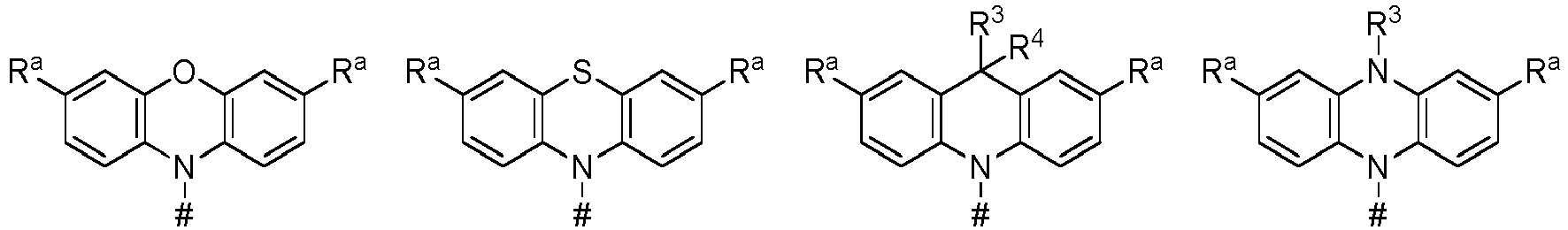


- In einer Ausführungsform weisen die erfindungsgemäßen organischen Moleküle eine Struktur der Formel III auf:

- In einer weiteren Ausführungsform weisen die erfindungsgemäßen organischen Moleküle eine Struktur der Formel lila auf:

Rc bei jedem Auftreten unabhängig voneinander ausgewählt aus der Gruppe bestehend aus Me, iPr, tBu, CN, CF3, Ph, das jeweils durch einen oder mehrere Reste ausgewählt aus Me, iPr, tBu, CN, CF3 oder Ph substituiert sein kann, Pyridinyl, das jeweils durch einen oder mehrere Reste ausgewählt aus Me, iPr, tBu, CN, CF3 oder Ph substituiert sein kann, Pyrimidinyl, das jeweils durch einen oder mehrere Reste ausgewählt aus Me, iPr, tBu, CN, CF3 oder Ph substituiert sein kann, Carbazolyl, das jeweils durch einen oder mehrere Reste ausgewählt aus Me, iPr, tBu, CN, CF3 oder Ph substituiert sein kann, Triazinyl, das jeweils durch einen oder mehrere Reste ausgewählt aus Me, iPr, tBu, CN, CF3 oder Ph substituiert sein kann, und N(Ph)2 ist. - In einer weiteren Ausführungsform weisen die erfindungsgemäßen organischen Moleküle eine Struktur der Formel IIIb auf:

- In einer weiteren Ausführungsform weisen die erfindungsgemäßen organischen Moleküle eine Struktur der Formel IIIc auf:

- In einer weiteren Ausführungsform weisen die erfindungsgemäßen organischen Moleküle eine Struktur der Formel IIId auf:

- In einer weiteren Ausführungsform weisen die erfindungsgemäßen organischen Moleküle eine Struktur der Formel IIIe auf:

- In einer weiteren Ausführungsform weisen die erfindungsgemäßen organischen Moleküle eine Struktur der Formel IIIf auf:
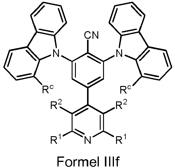
- In einer weiteren Ausführungsform weisen die erfindungsgemäßen organischen Moleküle eine Struktur der Formel IIIg auf:

- In einer weiteren Ausführungsform weisen die erfindungsgemäßen organischen Moleküle eine Struktur der Formel IIIh auf:

- In einer Ausführungsform weisen die erfindungsgemäßen organischen Moleküle eine Struktur der Formel IV auf:

- In einer weiteren Ausführungsform weisen die erfindungsgemäßen organischen Moleküle eine Struktur der Formel IVa auf:

- In einer weiteren Ausführungsform weisen die erfindungsgemäßen organischen Moleküle eine Struktur der Formel IVb auf:

- In einer weiteren Ausführungsform weisen die erfindungsgemäßen organischen Moleküle eine Struktur der Formel IVc auf:

- In einer weiteren Ausführungsform weisen die erfindungsgemäßen organischen Moleküle eine Struktur der Formel IVd auf:

- In einer weiteren Ausführungsform weisen die erfindungsgemäßen organischen Moleküle eine Struktur der Formel IVe auf:

- In einer weiteren Ausführungsform weisen die erfindungsgemäßen organischen Moleküle eine Struktur der Formel IVf auf:

- In einer weiteren Ausführungsform weisen die erfindungsgemäßen organischen Moleküle eine Struktur der Formel IVg auf:

- In einer weiteren Ausführungsform weisen die erfindungsgemäßen organischen Moleküle eine Struktur der Formel IVh auf:
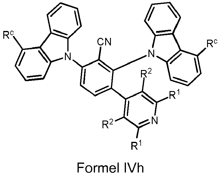
- In einer Ausführungsform weisen die erfindungsgemäßen organischen Moleküle eine Struktur der Formel V auf:

- In einer weiteren Ausführungsform weisen die erfindungsgemäßen organischen Moleküle eine Struktur der Formel Va auf:

- In einer weiteren Ausführungsform weisen die erfindungsgemäßen organischen Moleküle eine Struktur der Formel Vb auf:

- In einer weiteren Ausführungsform weisen die erfindungsgemäßen organischen Moleküle eine Struktur der Formel Vc auf:

- In einer weiteren Ausführungsform weisen die erfindungsgemäßen organischen Moleküle eine Struktur der Formel Vd auf:

- In einer weiteren Ausführungsform weisen die erfindungsgemäßen organischen Moleküle eine Struktur der Formel Ve auf:

- In einer weiteren Ausführungsform weisen die erfindungsgemäßen organischen Moleküle eine Struktur der Formel Vf auf:

- In einer weiteren Ausführungsform weisen die erfindungsgemäßen organischen Moleküle eine Struktur der Formel Vg auf:

- In einer weiteren Ausführungsform weisen die erfindungsgemäßen organischen Moleküle eine Struktur der Formel Vh auf:

- In einer Ausführungsform weisen die erfindungsgemäßen organischen Moleküle eine Struktur der Formel VI auf:

- In einer weiteren Ausführungsform weisen die erfindungsgemäßen organischen Moleküle eine Struktur der Formel VIa auf:

- In einer weiteren Ausführungsform weisen die erfindungsgemäßen organischen Moleküle eine Struktur der Formel Vlb auf:
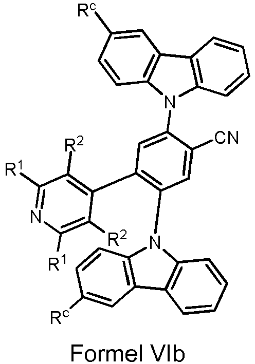
- In einer weiteren Ausführungsform weisen die erfindungsgemäßen organischen Moleküle eine Struktur der Formel Vlc auf:

- In einer weiteren Ausführungsform weisen die erfindungsgemäßen organischen Moleküle eine Struktur der Formel Vld auf:

- In einer weiteren Ausführungsform weisen die erfindungsgemäßen organischen Moleküle eine Struktur der Formel Vle auf:
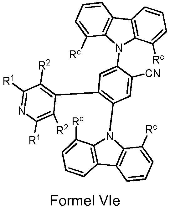
- In einer weiteren Ausführungsform weisen die erfindungsgemäßen organischen Moleküle eine Struktur der Formel VIf auf:

- In einer weiteren Ausführungsform weisen die erfindungsgemäßen organischen Moleküle eine Struktur der Formel Vlg auf:

- In einer weiteren Ausführungsform weisen die erfindungsgemäßen organischen Moleküle eine Struktur der Formel Vlh auf:

- In einer Ausführungsform weisen die erfindungsgemäßen organischen Moleküle eine Struktur der Formel VII auf:

- In einer weiteren Ausführungsform weisen die erfindungsgemäßen organischen Moleküle eine Struktur der Formel Vlla auf:

- In einer weiteren Ausführungsform weisen die erfindungsgemäßen organischen Moleküle eine Struktur der Formel VIIb auf:
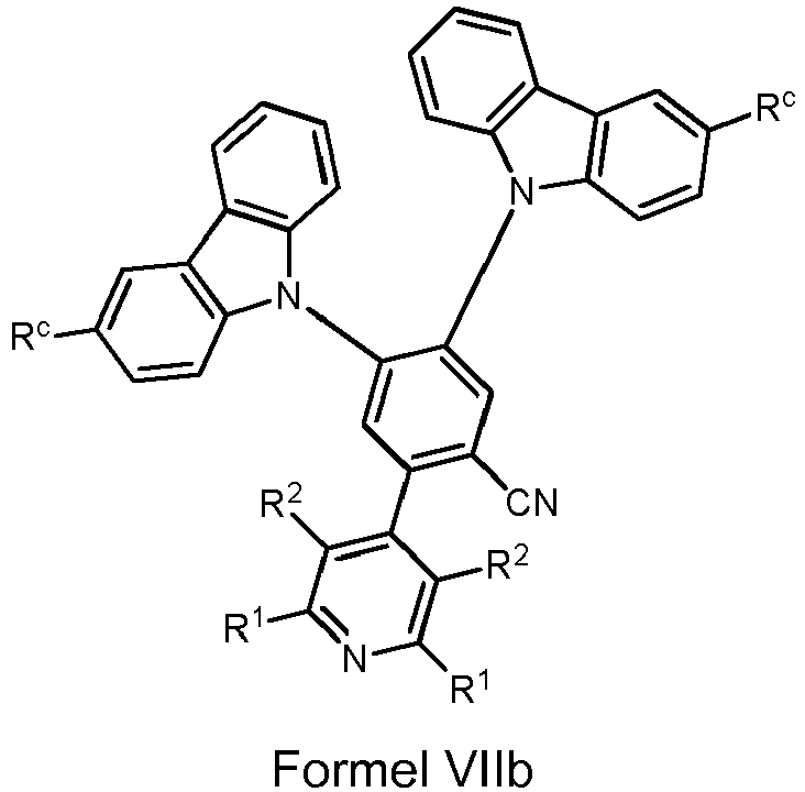
- In einer weiteren Ausführungsform weisen die erfindungsgemäßen organischen Moleküle eine Struktur der Formel VIIc auf:

- In einer weiteren Ausführungsform weisen die erfindungsgemäßen organischen Moleküle eine Struktur der Formel VIId auf:

- In einer weiteren Ausführungsform weisen die erfindungsgemäßen organischen Moleküle eine Struktur der Formel VIIe auf:

- In einer weiteren Ausführungsform weisen die erfindungsgemäßen organischen Moleküle eine Struktur der Formel VIIf auf:
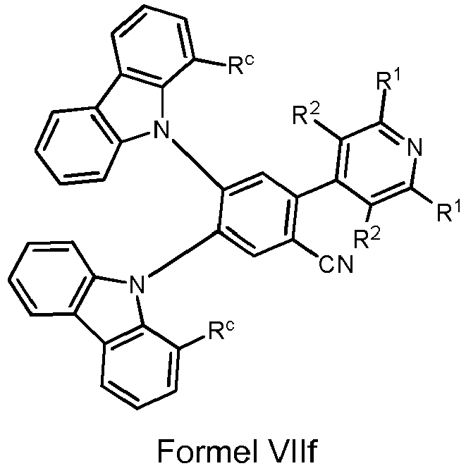
- In einer weiteren Ausführungsform weisen die erfindungsgemäßen organischen Moleküle eine Struktur der Formel VIIg auf:

- In einer weiteren Ausführungsform weisen die erfindungsgemäßen organischen Moleküle eine Struktur der Formel VIIh auf:

- In einer Ausführungsform weisen die erfindungsgemäßen organischen Moleküle eine Struktur der Formel VIII auf:

- In einer Ausführungsform der organischen Moleküle ist Rc ist bei jedem Auftreten unabhängig voneinander ausgewählt aus der Gruppe bestehend aus CN, CF3, Me, iPr, tBu, Ph, das jeweils durch einen oder mehrere Reste ausgewählt aus CN, CF3, Me, iPr, tBu, CN, CF3 oder Ph substituiert sein kann, und Carbazolyl, das jeweils durch einen oder mehrere Reste ausgewählt aus CN, CF3, Me, iPr, tBu, oder Ph substituiert sein kann.
- Im Sinne dieser Erfindung enthält eine Arylgruppe 6 bis 60 aromatische Ringatome; eine Heteroarylgruppe enthält 5 bis 60 aromatische Ringatome, von denen mindestens eines ein Heteroatom darstellt. Die Heteroatome sind insbesondere N, O und/oder S. Werden in der Beschreibung bestimmter Ausführungsformen der Erfindung andere, von der genannten Definition abweichende Definitionen angegeben, beispielsweise bezüglich der Zahl der aromatischen Ringatome oder der enthaltenen Heteroatome, so gelten diese.
- Unter einer Arylgruppe bzw. Heteroarylgruppe wird ein einfacher aromatischer Cyclus, also Benzol, oder ein einfacher heteroaromatischer Cyclus, beispielsweise Pyridin, Pyrimidin oder Thiophen, oder ein heteroaromatischer Polycyclus, beispielsweise Phenanthren, Chinolin oder Carbazol verstanden. Ein kondensierter (annelierter) aromatischer bzw. heteroaromatischer Polycyclus besteht im Sinne der vorliegenden Anmeldung aus zwei oder mehr miteinander kondensierten einfachen aromatischen bzw. heteroaromatischen Cyclen.
- Unter einer Aryl- oder Heteroarylgruppe, die jeweils mit den oben genannten Resten substituiert sein kann und die über beliebige Positionen am Aromaten bzw. Heteroaromaten verknüpft sein kann, werden insbesondere Gruppen verstanden, welche abgeleitet sind von Benzol, Naphthalin, Anthracen, Phenanthren, Pyren, Dihydropyren, Chrysen, Perylen, Fluoranthen, Benzanthracen, Benzphenanthren, Tetracen, Pentacen, Benzpyren, Furan, Benzofuran, Isobenzofuran, Dibenzofuran, Thiophen, Benzothiophen, Isobenzothiophen, Dibenzothiophen; Pyrrol, Indol, Isoindol, Carbazol, Pyridin, Chinolin, Isochinolin, Acridin, Phenanthridin, Benzo-5,6-chinolin, Isochinolin, Benzo-6,7-chinolin, Benzo-7,8-chinolin, Phenothiazin, Phenoxazin, Pyrazol, Indazol, Imidazol, Benzimidazol, Naphthimidazol, Phenanthrimidazol, Pyridimidazol, Pyrazinimidazol, Chinoxalinimidazol, Oxazol, Benzoxazol, Napthoxazol, Anthroxazol, Phenanthroxazol, Isoxazol, 1,2-Thiazol, 1,3-Thiazol, Benzothiazol, Pyridazin, Benzopyridazin, Pyrimidin, Benzpyrimidin, Chinoxalin, Pyrazin, Phenazin, Naphthyridin, Azacarbazol, Benzocarbolin, Phenanthrolin, 1,2,3-Triazol, 1,2,4-Triazol, Benztriazol, 1,2,3-Oxadiazol, 1,2,4-Oxadiazol, 1,2,5-Oxadiazol, 1,2,3,4-Tetrazin, Purin, Pteridin, Indolizin und Benzothiadiazol oder Kombinationen der genannten Gruppen.
- Unter einer cyclischen Alkyl-, Alkoxy- oder Thioalkoxygruppe wird hier eine monocyclische, eine bicyclische oder eine polycyclische Gruppe verstanden.
- Im Rahmen der vorliegenden Erfindung werden unter einer C1- bis C40-Alkylgruppe, in der auch einzelne H-Atome oder CH2-Gruppen durch die oben genannten Gruppen substituiert sein können, beispielsweise die Reste Methyl, Ethyl, n-Propyl, i-Propyl, Cyclopropyl, n-Butyl, i-Butyl, s-Butyl, t-Butyl, Cyclobutyl, 2-Methylbutyl, n-Pentyl, s-Pentyl, t-Pentyl, 2-Pentyl, neoPentyl, Cyclopentyl, n-Hexyl, s-Hexyl, t-Hexyl, 2-Hexyl, 3-Hexyl, neo-Hexyl, Cyclohexyl, 1-Methylcyclopentyl, 2-Methylpentyl, n-Heptyl, 2-Heptyl, 3-Heptyl, 4-Heptyl, Cycloheptyl, 1-Methylcyclohexyl, n-Octyl, 2-Ethylhexyl, Cyclooctyl, 1-Bicyclo[2,2,2]octyl, 2-Bicyclo[2,2,2]-octyl, 2-(2,6-Dimethyl)octyl, 3-(3,7-Dimethyl)octyl, Adamantyl, Trifluor-methyl, Pentafluorethyl, 2,2,2-Trifluorethyl, 1,1-Dimethyl-n-hex-1-yl-, 1,1-Dimethyl-n-hept-1-yl-, 1,1-Dimethyl-n-oct-1-yl-, 1,1-Dimethyl-n-dec-1-yl-, 1,1-Dimethyl-n-dodec-1-yl-, 1,1-Dimethyl-n-tetradec-1-yl-, 1,1-Dimethyl-n-hexadec-1-yl-, 1,1-Dimethyl-n-octadec-1-yl-, 1,1-Diethyl-n-hex-1-yl-, 1,1-Diethyl-n-hept-1-yl-, 1,1-Diethyl-n-oct-1-yl-, 1,1-Diethyl-n-dec-1-yl-, 1,1-Diethyl-n-dodec-1-yl-, 1,1-Diethyl-n-tetradec-1-yl-, 1,1-Diethyln-n-hexadec-1-yl-, 1,1-Diethyl-n-octadec-1-yl-, 1-(n-Propyl)-cyclohex-1-yl-, 1-(n-Butyl)-cyclohex-1-yl-, 1-(n-Hexyl)-cyclohex-1-yl-, 1-(n-Octyl)-cyclohex-1-yl- und 1-(n-Decyl)-cyclohex-1-yl- verstanden. Unter einer Alkenylgruppe werden beispielsweise Ethenyl, Propenyl, Butenyl, Pentenyl, Cyclopentenyl, Hexenyl, Cyclohexenyl, Heptenyl, Cycloheptenyl, Octenyl, Cyclooctenyl oder Cyclooctadienyl verstanden. Unter einer Alkinylgruppe werden beispielsweise Ethinyl, Propinyl, Butinyl, Pentinyl, Hexinyl, Heptinyl oder Octinyl verstanden. Unter einer C1- bis C40-Alkoxygruppe werden beispielsweise Methoxy, Trifluormethoxy, Ethoxy, n-Propoxy, i-Propoxy, n-Butoxy, i-Butoxy, s-Butoxy, t-Butoxy oder 2-Methylbutoxy verstanden.
- Eine Ausführungsform der Erfindung betrifft organische Moleküle, welche einen ΔE(S1-T1)-Wert zwischen dem untersten angeregten Singulett (S1)- und dem darunter liegenden Triplett (T1)-Zustand von nicht höher als 5000 cm-1, insbesondere nicht höher als 3000 cm-1, oder nicht höher als 1500 cm-1 oder 1000 cm-1 aufweisen und/oder eine Emissionslebensdauer von höchstens 150 µs, insbesondere von höchstens 100 µs, von höchsten 50 µs, oder von höchstens 10 µs aufweisen und/oder eine Hauptemissionsbande mit einer Halbwertsbreite kleiner als 0,55 eV, insbesondere kleiner als 0,50 eV, kleiner als 0,48 eV, oder kleiner als 0,45 eV aufweisen.
- Die erfindungsgemäßen organischen Moleküle zeigen insbesondere ein Emissionsmaximum bei zwischen 420 und 500 nm, zwischen 430 und 480 nm, oder zwischen 450 und 470 nm.
- In einer Ausführungsform weisen die Moleküle einen "blue material index" (BMI), den Quotienten aus der PLQY (in %) und ihrer CIEy-Farbkoordinate des von dem erfindungsgemäßen Molekül emittierten Lichts, von größer 150, insbesondere von größer 200, von größer 250 oder von größer 300 auf.
- In einem weiteren Aspekt betrifft die Erfindung ein Verfahren zur Herstellung eines erfindungsgemäßen organischen Moleküls der hier beschriebenen Art (optional mit einer Folgeumsetzung), wobei eine in 3,5-Position R1-substituierte und 2,6-Position R2-substituierte 4-Pyridinboronsäure oder ein entsprechender in 3,5-Position R1-substituierter und 2,6-Position R2-substituierter 4-Pyridinboronsäureester als Edukt eingesetzt wird.

- Im obigen Schema ist in einer Ausführungsform die chemische Gruppe CN durch CF3 ersetzt.
- In einer Ausführungsform wird eine in 3,5-Position R1-substituierte und in 2,6-Position R2-substituierte 4-Pyridinboronsäure oder ein entsprechender in 3,5-Position R1-substituierter und in 2,6-Position R2-substituierter 4-Pyridinboronsäureester als Edukt mit einem Bromdifluorbenzonitril in einer Palladium-katalysierten Kreuzkupplungsreaktion umgesetzt. Hierbei können erfindungsgemäß beispielhaft 4-Brom-2,6-difluorbenzonitril, 4-Brom-2,5-difluorbenzonitril, 4-Brom-3,5-difluorbenzonitril, 3-Brom-2,6-difluorbenzonitril, 3-Brom-5,6-difluorbenzonitril und 2-Brom-4,5-difluorbenzonitril eingesetzt werden. Das Produkt wird durch Deprotonierung des entsprechenden Amins und anschließender nukleophiler Substitution der zwei Fluorgruppen erhalten. Hierbei werden zwei Stickstoffheterozyklen im Sinne einer nukleophilen aromatischen Substitution mit einem Edukt E1 umgesetzt. Typische Bedingungen beinhalten die Verwendung einer Base wie beispielweise tribasisches Kaliumphosphat oder Natriumhydrid in einem aprotischen polaren Lösungsmittel wie beispielweise Dimetylsulfoxid (DMSO) oder N,N-Dimethylformamid (DMF).
- In einem weiteren Aspekt betrifft die Erfindung die Verwendung der organischen Moleküle als lumineszierender Emitter oder als Hostmaterial in einer organischen optoelektronischen Vorrichtung, insbesondere wobei die organische optoelektronische Vorrichtung ausgewählt ist aus der Gruppe bestehend aus:
- organischen lichtemittierenden Dioden (OLEDs),
- lichtemittierenden elektrochemischen Zellen,
- OLED-Sensoren, insbesondere in nicht hermetisch nach außen abgeschirmten Gas- und Dampf-Sensoren,
- organischen Dioden,
- organischen Solarzellen,
- organischen Transistoren,
- organischen Feldeffekttransistoren,
- organischen Lasern und
- Down-Konversions-Elementen.
- In einem weiteren Aspekt betrifft die Erfindung eine Zusammensetzung aufweisend oder bestehend aus:
- (a) mindestens einem erfindungsgemäßen organischen Molekül, insbesondere als Emitter und/oder Host, und
- (b) mindestens einem, d. h. einem oder mehreren (wie 2, 3, 4, ...) Emitter- und/oder Hostmaterialien, die von dem erfindungsgemäßen organischen Molekül verschiedenen ist bzw. sind und
- (c) optional einem oder mehreren Farbstoffen und/ oder einem oder mehreren organischen Lösungsmitteln.
- In einer Ausführungsform besteht die erfindungsgemäße Zusammensetzung aus einem erfindungsgemäßen organischen Molekül und einem oder mehreren Hostmaterialien. Das oder die Hostmaterialen weisen insbesondere Triplett (T1)- und Singulett (S1)- Energieniveaus auf, die energetisch höher liegen als die Triplett (T1)- und Singulett (S1)- Energieniveaus des erfindungsgemäßen organischen Moleküls. In einer Ausführungsform weist die Zusammensetzung neben dem erfindungsgemäßen organischen Molekül ein elektronendominantes und ein lochdominantes Hostmaterial auf. Das höchste besetzte Orbital (HOMO) und das niedrigste unbesetzte Orbital (LUMO) des lochdominanten Hostmaterials liegen energetisch insbesondere höher als das des elektronendominanten Hostmaterials. Das HOMO des lochdominanten Hostmaterials liegt energetisch unter dem HOMO des erfindungsgemäßen organischen Moleküls, während das LUMO des elektronendominanten Hostmaterials energetisch über dem LUMO des erfindungsgemäßen organischen Moleküls liegt. Um Exciplex-Formation zwischen Emitter und Hostmaterial oder Hostmaterialien zu vermeiden, sollten die Materialien so gewählt sein, dass die Energieabstände zwischen den jeweiligen Orbitalen gering sind. Der Abstand zwischen dem LUMO des elektronendominanten Hostmaterials und dem LUMO des erfindungsgemäßen organischen Moleküls beträgt insbesondere weniger als 0,5 eV, bevorzugt weniger als 0,3 eV, noch bevorzugter weniger als 0,2 eV. Der Abstand zwischen dem HOMO des lochdominanten Hostmaterials und dem HOMO des erfindungsgemäßen organischen Moleküls beträgt insbesondere weniger als 0,5 eV, bevorzugt weniger als 0,3 eV, noch bevorzugter weniger als 0,2 eV.
- In einem weiteren Aspekt betrifft die Erfindung eine organische optoelektronische Vorrichtung, die ein erfindungsgemäßes organisches Molekül oder eine erfindungsgemäße Zusammensetzung aufweist. Die organische optoelektronische Vorrichtung ist insbesondere ausgeformt als eine Vorrichtung ausgewählt aus der Gruppe bestehend aus organischer lichtemittierender Diode (OLED); lichtemittierender elektrochemischer Zelle; OLED-Sensor, insbesondere nicht hermetisch nach außen abgeschirmten Gas- und Dampf-Sensoren; organischer Diode; organischer Solarzelle; organischem Transistor; organischem Feldeffekttransistor; organischem Laser und Down-Konversion-Element.
- Eine organische optoelektronische Vorrichtung weist in einer Ausführungsform auf:
- ein Substrat,
- eine Anode und
- eine Kathode, wobei die Anode oder die Kathode auf das Substrat aufgebracht sind, und
- mindestens eine lichtemittierende Schicht, die zwischen Anode und Kathode angeordnet ist und die ein erfindungsgemäßes organisches Molekül aufweist, stellt einen weitere Ausführungsform der Erfindung dar.
- In einer Ausführungsform handelt es sich bei der optoelektronischen Vorrichtung um eine organische lichtemittierende Dioden (OLED). Eine typische OLED weist beispielsweise folgenden Schichtaufbau auf:
- 1. Substrat (Trägermaterial)
- 2. Anode
- 3. Lochinjektionsschicht (hole injection layer, HIL)
- 4. Lochtransportschicht (hole transport layer, HTL)
- 5. Elektronenblockierschicht (electron blocking layer, EBL)
- 6. Emitterschicht (emitting layer, EML)
- 7. Lochblockierschicht (hole blocking layer, HBL)
- 8. Elektronenleitschicht (electron transport layer, ETL)
- 9. Elektroneninjektionsschicht (electron injection layer, EIL)
- 10. Kathode.
- Dabei sind einzelne Schichten lediglich in optionaler Weise vorhanden. Weiterhin können mehrere dieser Schichten zusammenfallen. Und es können einzelne Schichten mehrfach im Bauteil vorhanden sein.
- Gemäß einer Ausführungsform ist mindestens eine Elektrode des organischen Bauelements transluzent ausgebildet. Hier wird mit "transluzent" eine Schicht bezeichnet, die durchlässig für sichtbares Licht ist. Dabei kann die transluzente Schicht klar durchscheinend, also transparent, oder zumindest teilweise Licht absorbierend und/oder teilweise Licht streuend sein, so dass die transluzente Schicht beispielsweise auch diffus oder milchig durchscheinend sein kann. Insbesondere ist eine hier als transluzent bezeichnete Schicht möglichst transparent ausgebildet, so dass insbesondere die Absorption von Licht so gering wie möglich ist.
- Gemäß einer weiteren Ausführungsform weist das organische Bauelement, insbesondere eine OLED, einen invertierten Aufbau auf. Der invertierte Aufbau zeichnet sich dadurch aus, dass sich die Kathode auf dem Substrat befindet und die anderen Schichten entsprechend invertiert aufgebracht werden:
- 1. Substrat (Trägermaterial)
- 2. Kathode
- 3. Elektroneninjektionsschicht (electron injection layer, EIL)
- 4. Elektronenleitschicht (electron transport layer, ETL)
- 5. Lochblockierschicht (hole blocking layer, HBL)
- 6. Emissionsschicht bzw. Emitterschicht (emitting layer, EML)
- 7. Elektronenblockierschicht (electron blocking layer, EBL)
- 8. Lochtransportschicht (hole transport layer, HTL)
- 9. Lochinjektionsschicht (hole injection layer, HIL)
- 10. Anode
- Dabei sind einzelne Schichten lediglich in optionaler Weise vorhanden. Weiterhin können mehrere dieser Schichten zusammenfallen. Und es können auch einzelne Schichten mehrfach im Bauteil vorhanden sein.
- In einer Ausführungsform wird bei der invertierten OLED die Anodenschicht des typischen Aufbaus, z. B. eine ITO-Schicht (Indium-Zinn-Oxid), als Kathode geschaltet.
- Gemäß einer weiteren Ausführungsform weist das organische Bauelement, insbesondere eine OLED, einen gestapelten Aufbau auf. Hierbei werden die einzelnen OLEDs übereinander und nicht wie üblich nebeneinander angeordnet. Durch einen gestapelten Aufbau kann die Erzeugung von Mischlicht ermöglicht werden. Beispielsweise kann dieser Aufbau bei der Erzeugung von weißem Licht eingesetzt werden, für dessen Erzeugung das gesamte sichtbare Spektrum typischerweise durch die Kombination des emittierten Lichts von blauen, grünen und roten Emittern abgebildet wird. Weiterhin können bei praktisch gleicher Effizienz und identischer Leuchtdichte signifikant längere Lebensdauern im Vergleich zu üblichen OLEDs erzielt werden. Für den gestapelten Aufbau wird optional eine sogenannte Ladungserzeugungsschicht (charge generation layer, CGL) zwischen zwei OLEDs eingesetzt. Diese besteht aus einer n-dotierten und einem p-dotierten Schicht, wobei die n-dotierte Schicht typischerweise näher an der Anode aufgebracht wird.
- In einer Ausführungsform - einer sogenannten Tandem-OLED - treten zwei oder mehr Emissionsschichten zwischen Anode und Kathode auf. In einer Ausführungsform sind drei Emissionsschichten übereinander angeordnet, wobei eine Emissionsschicht rotes Licht emittiert, eine Emissionsschicht grünes Licht emittiert und eine Emissionsschicht blaues Licht emittiert und optional weitere Ladungserzeugungs-, Blockier- oder Transportschichten zwischen den einzelnen Emissionsschichten aufgebracht sind. In einer weiteren Ausführungsform werden die jeweiligen Emissionsschichten direkt angrenzend aufgebracht. In einer weiteren Ausführungsform befindet sich jeweils eine Ladungserzeugungsschicht zwischen den Emissionsschichten. Weiterhin können in einer OLED direkt angrenzende und durch Ladungserzeugungsschichten getrennte Emissionsschichten kombiniert werden.
- Über den Elektroden und den organischen Schichten kann weiterhin noch eine Verkapselung angeordnet sein. Die Verkapselung kann beispielsweise in Form eines Glasdeckels oder in Form einer Dünnschichtverkapselung ausgeführt sein.
- Als Trägermaterial der optoelektronischen Vorrichtung kann beispielsweise Glas, Quarz, Kunststoff, Metall, ein Siliziumwafer oder jedes andere geeignete feste oder flexible, optional durchsichtige Material dienen. Das Trägermaterial kann beispielsweise ein oder mehrere Materialien in Form einer Schicht, einer Folie, einer Platte oder einem Laminat aufweisen.
- Als Anode der optoelektronischen Vorrichtung können beispielsweise transparente leitende Metalloxide wie beispielsweise ITO (Indium-Zinn-Oxid), Zinkoxid, Zinnoxid, Cadmiumoxid, Titanoxid, Indiumoxid oder Aluminiumzinkoxid (AZO), Zn2SnO4, CdSnO3, ZnSnO3, MgIn2O4, GaInO3, Zn2In2O5 oder In4Sn3O12 oder Mischungen unterschiedlicher transparenter leitender Oxide dienen.
- Als Materialien einer HIL können beispielsweise PEDOT:PSS (Poly-3,4-ethylendioxythiophen:Polystyrolsulfonsäure), PEDOT (Poly-3,4-ethylendioxythiophen), m-MTDATA (4,4',4"-Tris[phenyl(m-tolyl)amino]triphenylamin), Spiro-TAD (2,2',7,7'-Tetrakis(N,N-diphenylamino)-9,9-spirobifluoren), DNTPD (4,4'-Bis[N-[4-{N,N-bis(3-methylphenyl)amino}phenyl]-N-phenylamino]biphenyl), NPB (N,N'-Bis-(1-naphthalenyl)-N,N'-bis-phenyl-(1,1'-biphenyl)-4,4'-diamin), NPNPB (N,N'-Diphenyl-N,N'-di-[4-(N,N-diphenyl-amino)phenyl]benzol), MeO-TPD (N,N,N',N'-Tetrakis(4-methoxyphenyl)benzol), HAT-CN (1,4,5,8,9,11-Hexaazatriphenylen-hexacarbonitril) oder Spiro-NPD (N,N'-diphenyl-N,N'-Bis-(1-naphthyl)-9,9'-spirobifluorene-2,7-diamin) dienen. Beispielhaft ist die Schichtdicke 10-80 nm. Desweiteren können kleine Moleküle verwendet werden (z. B. Kupfer-Phthalocyanin (CuPc z. B. 10 nm dick)) oder Metalloxide wie beispielsweise MoO3, V2O5.
- Als Materialien einer HTL können tertiäre Amine, Carbazolderivate, mit Polystyrolsulfonsäure dotiertes Polyethylendioxythiophen, mit Camphersulfonsäure dotiertes Polyanilin poly-TPD (Poly(4-butylphenyl-diphenyl-amin)), [alpha]-NPD (Poly(4-butylphenyl-diphenyl-amin)), TAPC (4,4'-Cyclohexyliden-bis[N,N-bis(4-methylphenyl)benzenamin]), TCTA (Tris(4-carbazoyl-9-ylphenyl)amin), 2-TNATA (4,4',4"-Tris[2-naphthyl(phenyl)amino]triphenylamin), Spiro-TAD, DNTPD, NPB, NPNPB, MeO-TPD, HAT-CN oder TrisPcz (9,9'-Diphenyl-6-(9-phenyl-9H-carbazol-3-yl)-9H,9'H-3,3'-bicarbazol) dienen. Beispielhaft ist die Schichtdicke 10 nm bis 100 nm.
- Die HTL kann eine p-dotierte Schicht aufweisen, die einen anorganischen oder organischen Dotierstoff in einer organischen löcherleitenden Matrix aufweist. Als anorganischer Dotierstoff können beispielsweise Übergangsmetalloxide wie etwa Vanadiumoxid, Molybdänoxid oder Wolframoxid genutzt werden. Als organische Dotierstoffe können beispielsweise Tetrafluorotetracyanoquinodimethan (F4-TCNQ), Kupfer-Pentafluorobenzoat (Cu(I)pFBz) oder Übergangsmetallkomplexe verwendet werden. Beispielhaft ist die Schichtdicke 10 nm bis 100 nm.
- Als Materialien einer Elektronenblockierschicht können beispielsweise mCP (1,3-Bis(carbazol-9-yl)benzol), TCTA, 2-TNATA, mCBP (3,3-Di(9H-carbazol-9-yl)biphenyl), tris-Pcz (9,9'-Diphenyl-6-(9-phenyl-9H-carbazol-3-yl)-9H,9'H-3,3'-bicarbazol), CzSi (9-(4-tert-Butylphenyl)-3,6-bis(triphenylsilyl)-9H-carbazol) oder DCB (N,N'-Dicarbazolyl-1,4-dimethylbenzol) dienen. Beispielhaft ist die Schichtdicke 10 nm bis 50 nm.
- Die Emitter-Schicht EML oder Emissionsschicht besteht aus oder enthält Emittermaterial oder eine Mischung aufweisend mindestens zwei Emittermaterialien und optional ein oder mehreren Hostmaterialien. Geeignete Hostmaterialien sind beispielsweise mCP, TCTA, 2-TNATA, mCBP, CBP (4,4'-Bis-(N-carbazolyl)-biphenyl), Sif87 (Dibenzo[b,d]thiophen-2-yltriphenylsilan), Sif88 (Dibenzo[b,d]thiophen-2-yl)diphenylsilan), 9-[3-(Dibenzofuran-2-yl)phenyl]-9H-carbazol, 9-[3-(Dibenzofuran-2-yl)phenyl]-9H-carbazol, 9-[3-(Dibenzothiophen-2-yl)phenyl]-9H-carbazol, 9-[3,5-Bis(2-dibenzofuranyl)phenyl]-9H-carbazol, 9-[3,5-Bis(2-dibenzothiophenyl)phenyl]-9H-carbazol, T2T (2,4,6-Tris(biphenyl-3-yl)-1,3,5-triazin), T3T (2,4,6-Tris(triphenyl-3-yl)-1,3,5-triazin), TST (2,4,6-Tris(9,9'-spirobifluorene-2-yl)-1,3,5-triazin) und/oder DPEPO (Bis[2-((oxo)diphenylphosphino)phenyl]ether). In einer Ausführungsform enthält die EML 50-80 Gewichts-%, bevorzugt 60-75 Gewichts-% eines Hostmaterials ausgewählt aus der Gruppe bestehend aus CBP, mCP, mCBP, 9-[3-(Dibenzofuran-2-yl)phenyl]-9H-carbazol, 9-[3-(Dibenzofuran-2-yl)phenyl]-9H-carbazol, 9-[3-(Dibenzothiophen-2-yl)phenyl]-9H-carbazol, 9-[3,5-Bis(2-dibenzofuranyl)phenyl]-9H-carbazol und 9-[3,5-bis(2-Dibenzothiophenyl)phenyl]-9H-carbazol; 10-45 Gewichts-%, bevorzugt 15-30 Gewichts-% T2T und 5-40 Gewichts-%, bevorzugt 10-30 Gewichts-% eines erfindungsgemäßen organischen Moleküls als Emitter. Für im Grünen oder im Roten emittierendes Emittermaterial oder einer Mischung aufweisend mindestens zwei Emittermaterialien eignen sich die gängigen Matrixmaterialien wie CBP. Für im Blauen emittierendes Emittermaterial oder einer Mischung aufweisend mindestens zwei Emittermaterialien können UHG-Matrixmaterialien (Ultra-High energy Gap Materialien) (siehe z. B. M.E. Thompson et al., Chem. Mater. 2004, 16, 4743) oder andere sogenannten Wide-Gap-Matrixmaterialien eingesetzt werden. Beispielhaft ist die Schichtdicke 10 nm bis 250 nm.
- Die Lochblockierschicht HBL kann beispielsweise BCP (2,9-Dimethyl-4,7-diphenyl-1,10-phenanthrolin = Bathocuproin), Bis-(2-methyl-8-hydroxychinolinato)-(4-phenylphenolato)-aluminium(III) (BAlq), NBphen (2,9-Bis(naphthalen-2-yl)-4,7-diphenyl-1,10-phenanthrolin), Alq3 (Aluminium-tris(8-hydroxychinolin)), T2T, TSPO1 (Diphenyl-4-triphenylsilylphenyl-phosphinoxid) oder TCB/TCP (1,3,5-Tris(N-carbazolyl)benzol/ 1,3,5-tris(carbazol)-9-yl) benzol) aufweisen. Beispielhaft ist die Schichtdicke 10 nm bis 50 nm.
- Die Elektronentransportschicht ETL kann beispielsweise Materialien auf Basis von AlQ3, TSPO1, NBphen, BPyTP2 (2,7-Di(2,2'-bipyridin-5-yl)triphenyl), Sif87, Sif88, BmPyPhB (1,3-Bis[3,5-di(pyridin-3-yl)phenyl]benzol) oder BTB (4,4'-Bis-[2-(4,6-diphenyl-1,3,5-triazinyl)]-1,1'-biphenyl) aufweisen. Beispielhaft ist die Schichtdicke 10 nm bis 200 nm.
- Als Materialien einer dünnen Elektroneninjektionsschicht EIL können beispielsweise CsF, LiF, 8-Hydroxyquinolinolatolithium (Liq), Li2O, BaF2, MgO oder NaF verwendet werden.
- Als Materialien der Kathodenschicht können Metalle oder Legierungen dienen, beispielsweise Al, Al > AlF, Ag, Pt, Au, Mg, Ag:Mg. Typische Schichtdicken betragen 100 nm bis 200 nm. Insbesondere werden ein oder mehrere Metalle verwendet, die stabil an der Luft sind und/oder die selbstpassivierend, beispielsweise durch Ausbildung einer dünnen schützenden Oxidschicht, sind.
- Als Materialien zur Verkapselung sind beispielsweise Aluminiumoxid, Vanadiumoxid, Zinkoxid, Zirkoniumoxid, Titanoxid, Hafniumoxid, Lanthanoxid, Tantaloxid geeignet.
- In einer Ausführungsform der erfindungsgemäßen organischen optoelektronischen Vorrichtung ist das erfindungsgemäße organische Molekül als Emissionsmaterial in einer lichtemittierenden Schicht EML eingesetzt, wobei es entweder als Reinschicht oder in Kombination mit einem oder mehreren Hostmaterialien eingesetzt ist.
- Eine Ausführungsform der Erfindung betrifft organische optoelektronische Vorrichtungen, welche eine externe Quanteneffizienz (EQE) bei 1000 cd/m2 von größer 5 %, insbesondere von größer 8 %, insbesondere von größer 10 %, oder von größer 13 %, oder von größer 16 % und insbesondere von größer 20 % und/oder ein Emissionsmaximum bei einer Wellenlänge zwischen 420 nm und 500 nm, insbesondere zwischen 430 nm und 490 nm, oder zwischen 440 nm und 480 nm und insbesondere zwischen 450 nm und 470 nm und/oder einen LT80 Wert bei 500 cd/m2 von größer 30 h, insbesondere von größer 70 h, oder von größer 100 h, oder von größer 150 h und insbesondere von größer 200 h aufweisen.
- Der Massenanteil des erfindungsgemäßen organischen Moleküls an der Emitter-Schicht EML beträgt in einer weiteren Ausführungsform in einer lichtemittierenden Schicht in optischen Licht emittierenden Vorrichtungen, insbesondere in OLEDs, zwischen 1 % und 80 %. In einer Ausführungsform der erfindungsgemäßen organischen optoelektronischen Vorrichtung ist die lichtemittierende Schicht auf ein Substrat aufgebracht, wobei bevorzugt eine Anode und eine Kathode auf das Substrat aufgebracht sind und die lichtemittierende Schicht zwischen Anode und Kathode aufgebracht ist.
- Die lichtemittierende Schicht kann in einer Ausführungsform ausschließlich ein erfindungsgemäßes organisches Molekül in 100 % Konzentration aufweisen, wobei die Anode und die Kathode auf das Substrat aufgebracht sind, und die lichtemittierende Schicht zwischen Anode und Kathode aufgebracht ist.
- In einer Ausführungsform der erfindungsgemäßen organischen optoelektronischen Vorrichtung sind eine löcher- und elektroneninjizierende Schicht zwischen Anode und Kathode, und eine löcher- und elektronentransportierende Schicht zwischen löcher- und elektroneninjizierender Schicht, und die lichtemittierende Schicht zwischen löcher- und elektronentransportierender Schicht aufgebracht.
- Die organische optoelektronische Vorrichtung weist in einer weiteren Ausführungsform der Erfindung auf: ein Substrat, eine Anode, eine Kathode und mindestens je eine löcher- und elektroneninjizierende Schicht, und mindestens je eine löcher- und elektronentransportierende Schicht, und mindestens eine lichtemittierende Schicht, die erfindungsgemäßes organisches Molekül und ein oder mehrere Hostmaterialen aufweist, deren Triplett (T1)- und Singulett (S1)-Energieniveaus energetisch höher liegen als die Triplett (T1)- und Singulett (S1)-Energieniveaus des organischen Moleküls, wobei die Anode und die Kathode auf das Substrat aufgebracht ist, und die löcher- und elektroneninjizierende Schicht zwischen Anode und Kathode aufgebracht ist, und die löcher- und elektronentransportierende Schicht zwischen löcher- und elektroneninjizierender Schicht aufgebracht ist, und die lichtemittierende Schicht zwischen löcher- und elektronentransportierender Schicht aufgebracht ist.
- In einem weiteren Aspekt betrifft die Erfindung ein Verfahren zur Herstellung eines optoelektronischen Bauelements. Dabei wird ein erfindungsgemäßes organisches Molekül verwendet.
- In einer Ausführungsform umfasst das Herstellungsverfahren die Verarbeitung des erfindungsgemäßen organischen Moleküls mittels eines Vakuumverdampfungsverfahrens oder aus einer Lösung.
- Erfindungsgemäß ist auch ein Verfahren zur Herstellung einer erfindungsgemäßen optoelektronischen Vorrichtung, bei dem mindestens eine Schicht der optoelektronischen Vorrichtung
- mit einem Sublimationsverfahren beschichtet wird,
- mit einem OVPD (Organic Vapor Phase Deposition) Verfahren beschichtet wird,
- mit einer Trägergassublimation beschichtet wird, und/oder
- aus Lösung oder mit einem Druckverfahren hergestellt wird.
- Bei der Herstellung der erfindungsgemäßen optoelektronischen Vorrichtung werden bekannte Verfahren eingesetzt. Generell werden die Schichten einzeln auf ein geeignetes Substrat in aufeinanderfolgenden Abscheideverfahrensschritten aufgebracht. Bei der Gasphasenabscheidung können die gebräuchlichen Methoden, wie thermische Verdampfung, chemische Gasphasenabscheidung (CVD), physikalische Gasphasenabscheidung (PVD) angewendet werden. Für active matrix OLED (AMOLED) Displays erfolgt die Abscheidung auf eine AMOLED Backplane als Substrat.
- Alternativ können Schichten aus Lösungen oder Dispersionen in geeigneten Lösungsmitteln aufgebracht werden. Beispielhafte geeignete Beschichtungsverfahren sind Rotationsbeschichtung (spin-coating), Tauchbeschichtung (dip-coating) und Strahldruckmethoden. Die einzelnen Schichten können erfindungsgemäß sowohl über dasselbe als auch über jeweils verschiedene Beschichtungsmethoden hergestellt werden.
-

-

- 4-Pyridinboronsäure (1,80 Äquivalente), 4-Brom-2,6-difluorbenzonitril (1,00 Äquivalente), Pd2(dba)3 (0,02 Äquivalente), 2-Dicyclohexylphosphino-2',6'-dimethoxybiphenyl (SPhos) (0,08 Äquivalente) und tribasisches Kaliumphosphat (3,00 Äquivalente) werden unter Stickstoff in einem Toluol/Wasser-Gemisch (Verhältnis 6:1) bei 100 °C für 16 h gerührt. Anschließend wird die Reaktionsmischung in 600 mL gesättigte Natriumchlorid-Lösung gegeben und mit Ethylacetat (2 x 300 mL) extrahiert. Die vereinigten organischen Phasen werden mit gesättigte Natriumchlorid-Lösung gewaschen, über MgSO4 getrocknet und das Lösemittel entfernt. Das erhaltene Rohprodukt wird durch Flashchromatographie gereinigt und das Produkt als Feststoff erhalten.
- Erfindungsgemäß kann statt einer Boronsäure auch ein entsprechender Boronsäureester verwendet werden.
-

- Die Synthese von Z2 erfolgt analog AAV1, wobei 4-Pyridinboronsäure mit 3-Brom-2,6-difluorbenzonitril umgesetzt wird.
-
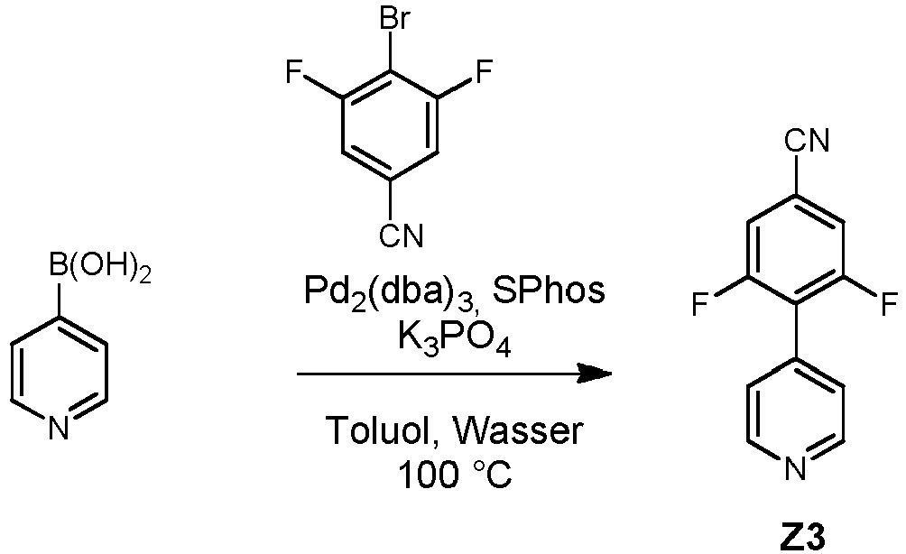
- Die Synthese von Z3 erfolgt analog AAV1, wobei 4-Pyridinboronsäure mit 4-Brom-3,5-difluorbenzonitril umgesetzt wird.
-

- Die Synthese von Z4 erfolgt analog AAV1, wobei 4-Pyridinboronsäure mit 4-Brom-2,5-difluorbenzonitril umgesetzt wird.
-

- Die Synthese von Z5 erfolgt analog AAV1, wobei 4-Pyridinboronsäure mit 2-Brom-4,5-difluorbenzonitril umgesetzt wird.
-
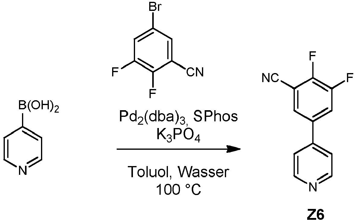
- Die Synthese von Z6 erfolgt analog AAV1, wobei 4-Pyridinboronsäure mit 3-Brom-5,6-difluorbenzonitril umgesetzt wird.
-


- Um die entsprechenden R1- und/oder R2-substituieren Produkte zu erhalten, wird statt 4-Pyridinboronsäure eine entsprechend substituierte 4-Pyridinboronsäure eingesetzt.
- Im speziellen entspricht D-H einem 3,6-substituierten Carbazol (z. B. 3,6-Dimethylcarbazol, 3,6-Diphenylcarbazol, 3,6-Di-tert-butylcarbazol), einem 2,7-substituierten Carbazol (z. B. 2,7-Dimethylcarbazol, 2,7-Diphenylcarbazol, 2,7-Di-tert-butylcarbazol), einem 1,8-substituierten Carbazol (z. B. 1,8-Dimethylcarbazol, 1,8-Diphenylcarbazol, 1,8-Di-tert-butylcarbazol), einem 1-substituierten Carbazol (z. B. 1-Methylcarbazol, 1-Phenylcarbazol, 1-tert-Butylcarbazol), einem 2-substituierten Carbazol (z. B. 2-Methylcarbazol, 2-Phenylcarbazol, 2-tert-Butylcarbazol) oder einem 3-substituierten Carbazol (z. B. 3-Methylcarbazol, 3-Phenylcarbazol, 3-tert-Butylcarbazol). Insbesondere kann ein Halogencarbazol, insbesondere 3-Bromcarbazol oder 3,6-Dibromcarbazol, als D-H eingesetzt werden, welches in einer Folgereaktion beispielsweise in eine entsprechende Boronsäure, beispielsweise (Carbazol-3-yl)boronsäure, oder in einen entsprechenden Boronsäureester, beispielsweise (Carbazol-3-yl)boronsäureester, beispielhaft durch Reaktion mit Bis(pinacol)boronsäureester (CAS-Nr. 73183-34-3), umgesetzt wird. In einer Folgereaktion können ein oder mehrere Reste Ra, welche als halogeniertes Edukt Ra-Hal, bevorzugt Ra-Cl und Ra-Br, eingesetzt werden, über eine Kupplungsreaktion an Stelle der Boronsäuregruppe oder der Boronsäureestergruppe eingeführt werden. Alternativ können ein oder mehrere Reste Ra durch Reaktion des zuvor eingeführten Halogencarbazols mit Boronsäuren des Restes Ra (Ra-B(OH)2) oder entsprechenden Boronsäureestern eingeführt werden.
- Alle Gläser (Küvetten und Substrate aus Quarzglas, Durchmesser: 1 cm) wurden nach jeder Benutzung gereinigt: Je dreimaliges Spülen mit Dichlormethan, Aceton, Ethanol, demineralisiertem Wasser, Einlegen in 5 % Hellmanex-Lösung für 24 h, gründliches Ausspülen mit demineralisiertem Wasser. Zum Trocknen wurden die optischen Gläser mit Stickstoff abgeblasen.
- Gerät: Spin150, SPS euro.
Die Probenkonzentration entsprach 10 mg/ml, angesetzt in Toluol oder Chlorbenzol. Programm: 1) 3 s bei 400 U/min; 2) 20 s bei 1000 U/min bei 1000 Upm/ s. 3) 10 s bei 4000 U/min bei 1000 Upm/s. Die Filme wurden nach dem Beschichten für 1 min bei 70 °C an Luft auf einer Präzisionsheizplatte von LHG getrocknet. - Photolumineszenzspektroskopie und TCSPC
Steady-state Emissionsspektroskopie wurde mit einem Fluoreszenzspektrometer der Horiba Scientific, Modell FluoroMax-4 durchgeführt, ausgestattet mit einer 150 W Xenon-Arc Lampe, Anregungs- und Emissionsmonochromatoren und einer Hamamatsu R928 Photomultiplier-Röhre, sowie einer "zeit-korrelierten Einphotonzähl" (Time-correlated single-photon counting, TCSPC)-Option. Emissions- und Anregungsspektren wurden korrigiert durch Standardkorrekturkurven. - Die Emissionsabklingzeiten wurden ebenfalls auf diesem System gemessen unter Verwendung der TCSPC-Methode mit dem FM-2013 Zubehör und einem TCSPC-Hub von Horiba Yvon Jobin. Anregungsquellen:
- NanoLED 370 (Wellenlänge: 371 nm, Pulsdauer: 1,1 ns)
- NanoLED 290 (Wellenlänge: 294 nm, Pulsdauer: <1 ns)
- SpectraLED 310 (Wellenlänge: 314 nm)
- SpectraLED 355 (Wellenlänge: 355 nm).
- Die Auswertung (exponentielles Fitten) erfolgte mit dem Softwarepaket DataStation und der DAS 6 Auswertungssoftware. Der Fit wurde über die Chi-Quadrat-Methode angegeben

- Die Messung der Photolumineszenzquantenausbeute (PLQY) erfolgte mittels eines Absolute PL Quantum Yield Measurement C9920-03G-Systems der Hamamatsu Photonics. Dieses besteht aus einer 150 W Xenon-Gasentladungslampe, automatisch justierbaren Czerny-Turner Monochromatoren (250 - 950 nm) und einer Ulbricht-Kugel mit hochreflektierender Spektralon-Beschichtung (einem Teflon-Derivat), die über ein Glasfaserkabel mit einem PMA-12 Vielkanaldetektor mit BT- (back thinned-) CCD-Chip mit 1024 x 122 Pixeln (Größe 24 x 24 µm) verbunden ist. Die Auswertung der Quanteneffizienz und der CIE-Koordinaten erfolgte mit Hilfe der Software U6039-05 Version 3.6.0.
- Das Emissionsmaximum wird in nm, die Quantenausbeute φ in % und die CIE-Farbkoordinaten als x,y-Werte angegeben.
- Die Photolumineszenzquantenausbeute wurde nach folgendem Protokoll bestimmt:
- 1) Durchführung der Qualitätssicherung: Als Referenzmaterial dient Anthracene in Ethanol mit bekannter Konzentration.
- 2) Ermitteln der Anregungswellenlänge: Es wurde zuerst das Absorbtionsmaximum des organischen Moleküls bestimmt und mit diesem angeregt.
- 3) Durchführung der Probenmessung:
Es wurde von entgasten Lösungen und Filmen unter Stickstoff-Atmosphäre die absolute Quantenausbeute bestimmt. - Die Berechnung erfolgte systemintern nach folgender Gleichung:

- Mit den erfindungsgemäßen organischen Molekülen können OLED-Devices mittels Vakuum-Sublimationstechnik erstellt werden.
- Diese noch nicht optimierten OLEDs können standardmäßig charakterisiert werden; hierfür werden die Elektrolumineszenzspektren, die externe Quanteneffizienz (gemessen in %) in Abhängigkeit von der Helligkeit, berechnet aus dem von der Fotodiode detektiertem Licht, den Elektrolumineszenzspektren und dem Strom aufgenommen.
- HPLC-MS Spektroskopie wurde mit einer HPLC-Anlage der Firma Agilent (1100er Serie) mit einem angeschlossenen MS-Detektor (Thermo LTQ XL) gemessen. Für die HPLC wurde eine Eclipse Plus C18 Säule von Agilent mit einer Partikelgröße von 3,5 µm, einer Länge von 150 mm und einem Innendurchmesser von 4,6 mm eingesetzt. Es wurde ohne Vorsäule und bei Raumtemperatur mit den Lösemitteln Acetonitril, Wasser und Tetrahydrofuran in diesen Konzentrationen gearbeitet:
Lösemittel A: H2O (90%) MeCN (10%) Lösemittel B: H2O (10%) MeCN (90%) Lösemittel C: THF (100%) - Es wurde mit einem Einspritzvolumen von 15 µL und einer Konzentration von 10 µg/mL mit diesem Gradienten gearbeitet:
Fluss [ml/min] Zeit [min] A[%] B[%] C[%] Druck [bar] 0,3 0 80 20 - 115 0,3 5 80 20 - 115 0,3 14 0 90 10 65 0,3 25 0 90 10 65 0,3 26 80 20 - 115 0,3 33 80 20 - 115 - Die Ionisation der Probe erfolgt durch APCI (atmospheric pressure chemical ionization).
-

- Beispiel 1 wurde nach AAV1 (Ausbeute 62 %) und AAV7 hergestellt (Ausbeute 91 %).
MS (HPLC-MS), m/z (Retentionszeit): 510, (6,18 min)
Figur 1 zeigt das Emissionsspektrum von Beispiel 1 (10 % in PMMA). Das Emissionsmaximum liegt bei 460 nm. Die Photolumineszenzquantenausbeute (PLQY) beträgt 74 % und die Halbwertsbreite beträgt 0,43 eV. -

- Beispiel 2 wurde nach AAV1 (Ausbeute 62 %) und AAV7 (Ausbeute 90 %) hergestellt.MS (HPLC-MS), m/z (Retentionszeit): 566, (13,78 min)
Figur 2 zeigt das Emissionsspektrum von Beispiel 2 (10 % in PMMA). Das Emissionsmaximum liegt bei 485 nm. Die Photolumineszenzquantenausbeute (PLQY) beträgt 75 % und die Halbwertsbreite beträgt 0,43 eV. Die Emissionsabklingzeit beträgt 8 µs. -

- Beispiel 3 wurde nach AAV1 (Ausbeute 62 %) und AAV7 (Ausbeute 25 %) hergestellt.
MS (HPLC-MS), m/z (Retentionszeit): 734, (21,78 min)
R f = 0,17 (Cyclohexan/Ethylacetat 5:1).
Figur 3 zeigt das Emissionsspektrum von Beispiel 3 (10 % in PMMA). Das Emissionsmaximum liegt bei 478 nm. Die Photolumineszenzquantenausbeute (PLQY) beträgt 72 % und die Halbwertsbreite beträgt 0,44 eV. Die Emissionsabklingzeit beträgt 12 µs. -

- Beispiel 4 wurde nach AAV1 (Ausbeute 62 %) und AAV7 hergestellt (Ausbeute 74 %).
MS (HPLC-MS), m/z (Retentionszeit): 814, (18,61 min)
R f = 0,1 (Cyclohexan/Ethylacetat 5:1).
Figur 4 zeigt das Emissionsspektrum von Beispiel 4 (10 % in PMMA). Das Emissionsmaximum liegt bei 489 nm. Die Photolumineszenzquantenausbeute (PLQY) beträgt 73 % und die Halbwertsbreite beträgt 0,44 eV. Die Emissionsabklingzeit beträgt 5 µs. -

- Beispiel 5 wurde nach AAV1 (Ausbeute 62 %) und AAV7 hergestellt (Ausbeute 66 %).
MS (HPLC-MS), m/z (Retentionszeit): 662, (15,12 min)
R f = 0,07 (Cyclohexan/Ethylacetat 5:1).
Figur 5 zeigt das Emissionsspektrum von Beispiel 5 (10 % in PMMA). Das Emissionsmaximum liegt bei 483 nm. Die Photolumineszenzquantenausbeute (PLQY) beträgt 69 % und die Halbwertsbreite beträgt 0,46 eV. Die Emissionsabklingzeit beträgt 13 µs. -

- Beispiel 6 wurde nach AAV1 (Ausbeute 62 %) und AAV7 hergestellt (Ausbeute 81 %).
MS (HPLC-MS), m/z (Retentionszeit): 840, (8,23 min)
R f = 0,24 (Cyclohexan/Ethylacetat 5:1).
Figur 6 zeigt das Emissionsspektrum von Beispiel 6 (10 % in PMMA). Das Emissionsmaximum liegt bei 497 nm. Die Photolumineszenzquantenausbeute (PLQY) beträgt 52 % und die Halbwertsbreite beträgt 0,50 eV. Die Emissionsabklingzeit beträgt 9 µs. -

- Beispiel 7 wurde nach AAV4 (Ausbeute 40 %) und AAV7 hergestellt (Ausbeute 73 %).
MS (HPLC-MS), m/z (Retentionszeit): 566, (15,39 min)
R f = 0,27 (Cyclohexan/Ethylacetat 5:1).
Figur 7 zeigt das Emissionsspektrum von Beispiel 7 (10 % in PMMA). Das Emissionsmaximum liegt bei 472 nm. Die Photolumineszenzquantenausbeute (PLQY) beträgt 84 % und die Halbwertsbreite beträgt 0,42 eV. -

- Beispiel 8 wurde nach AAV4 (Ausbeute 40 %) und AAV7 hergestellt (Ausbeute 57 %).
MS (HPLC-MS), m/z (Retentionszeit): 814, (19,46 min)
R f = 0,26 (Cyclohexan/Ethylacetat 5:1).
Figur 8 zeigt das Emissionsspektrum von Beispiel 8 (10 % in PMMA). Das Emissionsmaximum liegt bei 475 nm. Die Photolumineszenzquantenausbeute (PLQY) beträgt 84 % und die Halbwertsbreite beträgt 0,43 eV. -

- Beispiel 9 wurde nach AAV4 (Ausbeute 40 %) und AAV7 hergestellt (Ausbeute 74 %).
MS (HPLC-MS), m/z (Retentionszeit): 630, (4,93 min)
R f = 0,05 (Cyclohexan/Ethylacetat 5:1).
Figur 9 zeigt das Emissionsspektrum von Beispiel 9 (10 % in PMMA). Das Emissionsmaximum liegt bei 511 nm. Die Photolumineszenzquantenausbeute (PLQY) beträgt 41 % und die Halbwertsbreite beträgt 0,46 eV. -

- Beispiel 10 wurde nach AAV5 (Ausbeute 41 %) und AAV7 (Ausbeute 32 %) hergestellt.
MS (HPLC-MS), m/z (Retentionszeit): 630, (4,29 min)
Figur 10 zeigt das Emissionsspektrum von Beispiel 10 (10 % in PMMA). Das Emissionsmaximum liegt bei 501 nm. Die Photolumineszenzquantenausbeute (PLQY) beträgt 59% und die Halbwertsbreite beträgt 0,49 eV. -

- Beispiel 11 wurde nach AAV1 (Ausbeute 62 %) und AAV7 (Ausbeute 78 %) hergestellt.
MS (HPLC-MS), m/z (Retentionszeit): 662, (14,14 min)
Figur 11 zeigt das Emissionsspektrum von Beispiel 11 (10 % in PMMA). Das Emissionsmaximum liegt bei 462 nm. Die Photolumineszenzquantenausbeute (PLQY) beträgt 55 % und die Halbwertsbreite beträgt 0,45 eV. -
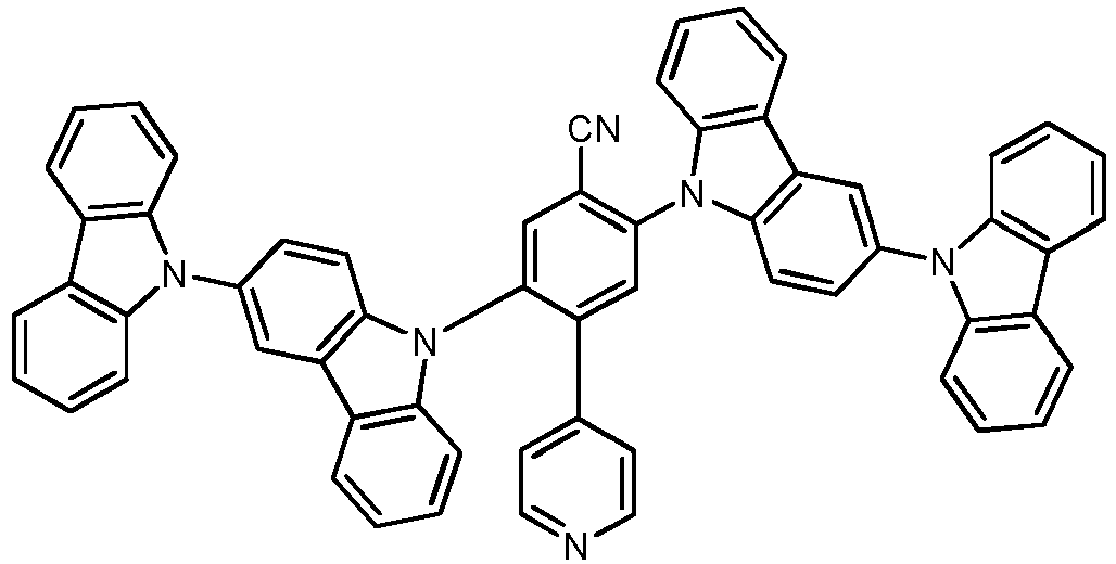
- Beispiel 12 wurde nach AAV4 (Ausbeute 40 %) und AAV7 (Ausbeute 38 %) hergestellt.
MS (HPLC-MS), m/z (Retentionszeit): 841, (20,13 min)
Figur 12 zeigt das Emissionsspektrum von Beispiel 12 (10 % in PMMA). Das Emissionsmaximum liegt bei 482 nm. Die Photolumineszenzquantenausbeute (PLQY) beträgt 61 % und die Halbwertsbreite beträgt 0,51 eV. -

- Beispiel 13 wurde nach AAV4 (Ausbeute 40 %) und AAV7 (Ausbeute 52 %) hergestellt.
MS (HPLC-MS), m/z (Retentionszeit): 735, (23,35 min)
Figur 13 zeigt das Emissionsspektrum von Beispiel 13 (10 % in PMMA). Das Emissionsmaximum liegt bei 471 nm. Die Photolumineszenzquantenausbeute (PLQY) beträgt 81 % und die Halbwertsbreite beträgt 0,42 eV. -

- Beispiel 14 wurde nach AAV4 (Ausbeute 40 %) und AAV7 (Ausbeute 66 %) hergestellt.
MS (HPLC-MS), m/z (Retentionszeit): 623, (6,65 min)
Figur 14 zeigt das Emissionsspektrum von Beispiel 14 (10 % in PMMA). Das Emissionsmaximum liegt bei 474 nm. Die Photolumineszenzquantenausbeute (PLQY) beträgt 75 % und die Halbwertsbreite beträgt 0,44 eV. Die Emissionsabklingzeit beträgt 38 µs. -
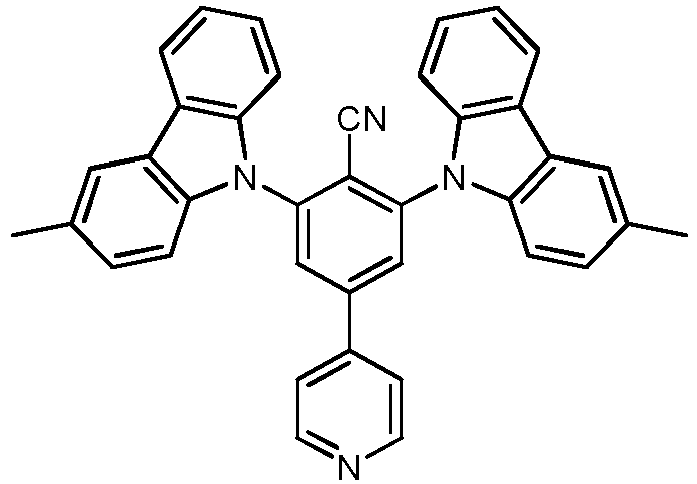
- Beispiel 15 wurde nach AAV1 (Ausbeute 62 %) und AAV7 (Ausbeute 72 %) hergestellt.
Figur 15 zeigt das Emissionsspektrum von Beispiel 15 (10% in PMMA). Das Emissionsmaximum liegt bei 475 nm. Die Photolumineszenzquantenausbeute (PLQY) beträgt 68 % und die Halbwertsbreite beträgt 0,44 eV. Die Emissionsabklingzeit beträgt 24 µs. -

- Beispiel 16 wurde nach AAV1 (Ausbeute 62 %) und AAV7 (Ausbeute 29 %) hergestellt.
Figur 16 zeigt das Emissionsspektrum von Beispiel 16 (10% in PMMA). Das Emissionsmaximum liegt bei 470 nm. Die Photolumineszenzquantenausbeute (PLQY) beträgt 65 % und die Halbwertsbreite beträgt 0,45 eV. Die Emissionsabklingzeit beträgt 56 µs. -

- Beispiel 17 wurde nach AAV1 (Ausbeute 62 %) und AAV7 (Ausbeute 51 %) hergestellt.
Figur 17 zeigt das Emissionsspektrum von Beispiel 17 (10% in PMMA). Das Emissionsmaximum liegt bei 476 nm. Die Photolumineszenzquantenausbeute (PLQY) beträgt 66 % und die Halbwertsbreite beträgt 0,43 eV. Die Emissionsabklingzeit beträgt 23 µs. -

- Beispiel 18 wurde mit einer 2-Methyl-4-Pyridinboronsäure statt einer 4-Pyridinboronsäure nach AAV1 (Ausbeute 36 %) und AAV7 (Ausbeute 90 %) hergestellt.
Figur 18 zeigt das Emissionsspektrum von Beispiel 18 (10% in PMMA). Das Emissionsmaximum liegt bei 483 nm. Die Photolumineszenzquantenausbeute (PLQY) beträgt 71 % und die Halbwertsbreite beträgt 0,44 eV. Die Emissionsabklingzeit beträgt 5 µs. -

- Beispiel 19 wurde nach AAV1 (Ausbeute 62 %) und AAV7 (Ausbeute 88 %) hergestellt.
Figur 19 zeigt das Emissionsspektrum von Beispiel 19 (10% in PMMA). Das Emissionsmaximum liegt bei 510 nm. Die Photolumineszenzquantenausbeute (PLQY) beträgt 38 % und die Halbwertsbreite beträgt 0,50 eV. Die Emissionsabklingzeit beträgt 3 µs. -

- Beispiel 20 wurde nach AAV1 (Ausbeute 62 %) und AAV7 (Ausbeute 9 %) hergestellt.
Figur 20 zeigt das Emissionsspektrum von Beispiel 20 (10% in PMMA). Das Emissionsmaximum liegt bei 498 nm. Die Photolumineszenzquantenausbeute (PLQY) beträgt 40 % und die Halbwertsbreite beträgt 0,46 eV. Die Emissionsabklingzeit beträgt 4 µs. -

- Beispiel 21 wurde mit einer 2-Methyl-4-Pyridinboronsäure statt einer 4-Pyridinboronsäure nach AAV1 (Ausbeute 36 %) und AAV7 (Ausbeute 71 %) hergestellt.
Figur 21 zeigt das Emissionsspektrum von Beispiel 21 (10 % in PMMA). Das Emissionsmaximum liegt bei 477 nm. Die Photolumineszenzquantenausbeute (PLQY) beträgt 74 % und die Halbwertsbreite beträgt 0,43 eV. Die Emissionsabklingzeit beträgt 14 µs. -

- Beispiel 22 wurde nach AAV1 (Ausbeute 62 %) und AAV7 (Ausbeute 73 %) hergestellt.
Figur 22 zeigt das Emissionsspektrum von Beispiel 22 (10% in PMMA). Das Emissionsmaximum liegt bei 493 nm. Die Photolumineszenzquantenausbeute (PLQY) beträgt 63 % und die Halbwertsbreite beträgt 0,46 eV. Die Emissionsabklingzeit beträgt 5 µs. -

- Beispiel 23 wurde mit einer 2-Methyl-4-Pyridinboronsäure statt einer 4-Pyridinboronsäure nach AAV1 (Ausbeute 36 %) und AAV7 (Ausbeute 86 %) hergestellt.
Figur 23 zeigt das Emissionsspektrum von Beispiel 23 (10 % in PMMA). Das Emissionsmaximum liegt bei 472 nm. Die Photolumineszenzquantenausbeute (PLQY) beträgt 76 % und die Halbwertsbreite beträgt 0,43 eV. Die Emissionsabklingzeit beträgt 35 µs. -

- Beispiel 24 wurde mit einer 2-Methyl-4-Pyridinboronsäure statt einer 4-Pyridinboronsäure nach AAV1 (Ausbeute 36 %) und AAV7 (Ausbeute 99 %) hergestellt.
Figur 24 zeigt das Emissionsspektrum von Beispiel 24 (10 % in PMMA). Das Emissionsmaximum liegt bei 477 nm. Die Photolumineszenzquantenausbeute (PLQY) beträgt 65 % und die Halbwertsbreite beträgt 0,44 eV. Die Emissionsabklingzeit beträgt 12 µs. -

- Beispiel 25 wurde mit einer 2-Methyl-4-Pyridinboronsäure statt einer 4-Pyridinboronsäure nach AAV1 (Ausbeute 36 %) und AAV7 (Ausbeute 42 %) hergestellt.
Figur 25 zeigt das Emissionsspektrum von Beispiel 25 (10% in PMMA). Das Emissionsmaximum liegt bei 466 nm. Die Photolumineszenzquantenausbeute (PLQY) beträgt 76 % und die Halbwertsbreite beträgt 0,45 eV. Die Emissionsabklingzeit beträgt 73 µs. -

- Beispiel 26 wurde mit einer 2-Methyl-4-Pyridinboronsäure statt einer 4-Pyridinboronsäure nach AAV1 (Ausbeute 36 %) und AAV7 (Ausbeute 78 %) hergestellt.
Figur 26 zeigt das Emissionsspektrum von Beispiel 26 (10 % in PMMA). Das Emissionsmaximum liegt bei 473 nm. Die Photolumineszenzquantenausbeute (PLQY) beträgt 71 % und die Halbwertsbreite beträgt 0,46 eV. Die Emissionsabklingzeit beträgt 65 µs. -

- Beispiel 27 wurde nach AAV3 (Ausbeute 10 %) und AAV7 (Ausbeute 2 %) hergestellt.
Figur 27 zeigt das Emissionsspektrum von Beispiel 27 (10% in PMMA). Das Emissionsmaximum liegt bei 467 nm. Die Photolumineszenzquantenausbeute (PLQY) beträgt 68 % und die Halbwertsbreite beträgt 0,45 eV. -

- Beispiel 28 wurde nach AAV1 (Ausbeute 62 %) und AAV7 (Ausbeute 23 %) hergestellt.
Figur 28 zeigt das Emissionsspektrum von Beispiel 28 (10% in PMMA). Das Emissionsmaximum liegt bei 465 nm. Die Photolumineszenzquantenausbeute (PLQY) beträgt 33 % und die Halbwertsbreite beträgt 0,52 eV. -

- Beispiel 29 wurde durch die Umsetzung von 2,6-Dichlor-4-iodpyridin (1,0 Äquivalente) mit einem 4-Cyano-3,5-difluorbenzol-boronsäureester (1,1 Äquivalente) unter Reaktionsbedingungen analog zu AAV1 (Ausbeute 80 %), anschließender Umsetzung mit Phenylboronsäure (2,5 Äquivalente) in einem 1,4-Dioxane/Wasser-Gemisch (Verhältnis 10:1) bei 100°C und einer Reaktionszeit von 24 h (Ausbeute 38 %) und anschließender Umsetzung nach AAV7 (Ausbeute 71 %) hergestellt.
Figur 29 zeigt das Emissionsspektrum von Beispiel 29 (10% in PMMA). Das Emissionsmaximum liegt bei 492 nm. Die Photolumineszenzquantenausbeute (PLQY) beträgt 76 % und die Halbwertsbreite beträgt 0,43 eV. Die Emissionsabklingzeit beträgt 6 µs. -

- Beispiel 30 wurde durch die Umsetzung von 2,6-Dichlor-4-iodpyridin (1,0 Äquivalente) mit einem 4-Cyano-3,5-difluorbenzol-boronsäureester (1,1 Äquivalente) unter Reaktionsbedingungen analog zu AAV1 (Ausbeute 80 %), anschließender Umsetzung mit Phenylboronsäure (2,5 Äquivalente) in einem 1,4-Dioxane/Wasser-Gemisch (Verhältnis 10:1) bei 100°C und einer Reaktionszeit von 24 h (Ausbeute 38 %) und anschließender Umsetzung nach AAV7 (Ausbeute 25%) hergestellt.
Figur 30 zeigt das Emissionsspektrum von Beispiel 30 (10 % in PMMA). Das Emissionsmaximum liegt bei 474 nm. Die Photolumineszenzquantenausbeute (PLQY) beträgt 81 % und die Halbwertsbreite beträgt 0,42 eV. Die Emissionsabklingzeit beträgt 27 µs. -

- Beispiel 31 wurde durch die Umsetzung von 4-Brom-2,6-dimethylpyridin (1,0 Äquivalente) mit einem 4-Cyano-3,5-difluorbenzol-boronsäureester (1,3 Äquivalente) unter Reaktionsbedingungen analog zu AAV1 (Ausbeute 45 %) und anschließender Umsetzung nach AAV7 (Ausbeute 15 %) hergestellt.
Figur 31 zeigt das Emissionsspektrum von Beispiel 31 (10% in PMMA). Das Emissionsmaximum liegt bei 479 nm. Die Photolumineszenzquantenausbeute (PLQY) beträgt 72 % und die Halbwertsbreite beträgt 0,44 eV. Die Emissionsabklingzeit beträgt 18 µs. -

- Beispiel 32 wurde AAV1 (Ausbeute 62 %) und AAV7 (Ausbeute 41 %) hergestellt.
Figur 32 zeigt das Emissionsspektrum von Beispiel 31 (10 % in PMMA). Das Emissionsmaximum liegt bei 491 nm. Die Photolumineszenzquantenausbeute (PLQY) beträgt 52 % und die Halbwertsbreite beträgt 0,48 eV. Die Emissionsabklingzeit beträgt 12 µs. -

- Beispiel 33 wurde durch die Umsetzung von 2,6-Dichlor-4-iodpyridin (1,0 Äquivalente) mit einem 4-Cyano-3,5-difluorbenzol-boronsäureester (1,1 Äquivalente) unter Reaktionsbedingungen analog zu AAV1 (Ausbeute 65 %), anschließender Umsetzung mit Phenylboronsäure (2,5 Äquivalente) in einem 1,4-Dioxane/Wasser-Gemisch (Verhältnis 10:1) bei 100°C und einer Reaktionszeit von 24 h (Ausbeute 96 %) und anschließender Umsetzung nach AAV7 (Ausbeute 57 %) hergestellt.
Figur 33 zeigt das Emissionsspektrum von Beispiel 33 (10 % in PMMA). Das Emissionsmaximum liegt bei 476 nm. Die Photolumineszenzquantenausbeute (PLQY) beträgt 71 % und die Halbwertsbreite beträgt 0,45 eV. Die Emissionsabklingzeit beträgt 186 µs. -
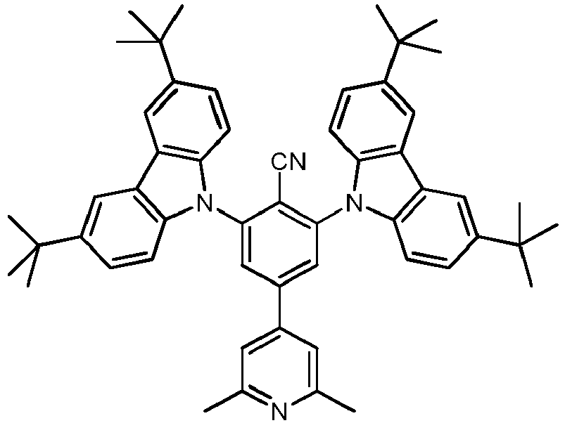
- Beispiel 34 wurde durch die Umsetzung von 4-Brom-2,6-dimethylpyridin (1,0 Äquivalente) mit einem 4-Cyano-3,5-difluorbenzol-boronsäureester (1,3 Äquivalente) unter Reaktionsbedingungen analog zu AAV1 (Ausbeute 45 %) und anschließender Umsetzung nach AAV7 (Ausbeute 50 %) hergestellt.
Figur 34 zeigt das Emissionsspektrum von Beispiel 34 (10% in PMMA). Das Emissionsmaximum liegt bei 471 nm. Die Photolumineszenzquantenausbeute (PLQY) beträgt 72 % und die Halbwertsbreite beträgt 0,42 eV. Die Emissionsabklingzeit beträgt 22 µs. -

- Beispiel 35 wurde durch die Umsetzung von 4-Brom-2,6-dimethylpyridin (1,0 Äquivalente) mit einem 4-Cyano-3,5-difluorbenzol-boronsäureester (1,3 Äquivalente) unter Reaktionsbedingungen analog zu AAV1 (Ausbeute 45 %) und anschließender Umsetzung nach AAV7 (Ausbeute 43 %) hergestellt.
Figur 35 zeigt das Emissionsspektrum von Beispiel 35 (10 % in PMMA). Das Emissionsmaximum liegt bei 450 nm. Die Photolumineszenzquantenausbeute (PLQY) beträgt 62 % und die Halbwertsbreite beträgt 0,44 eV. -

- Beispiel 36 wurde durch die Umsetzung von 4-Chlor-3-phenylpyridin (1,0 Äquivalente) mit einem 4-Cyano-3,5-difluorbenzol-boronsäureester (1,1 Äquivalente) unter Reaktionsbedingungen analog zu AAV1 (Ausbeute 77 %) und anschließender Umsetzung nach AAV7 (Ausbeute 37 %) hergestellt.
Figur 36 zeigt das Emissionsspektrum von Beispiel 36 (10% in PMMA). Das Emissionsmaximum liegt bei 468 nm. Die Photolumineszenzquantenausbeute (PLQY) beträgt 55 % und die Halbwertsbreite beträgt 0,47 eV. Die Emissionsabklingzeit beträgt 272 µs. -
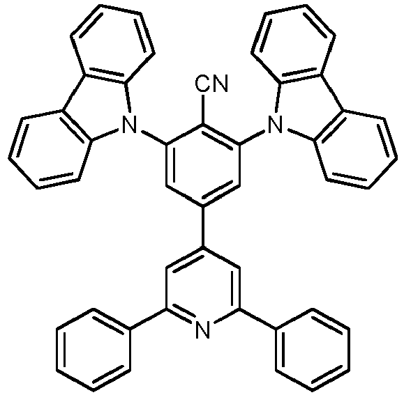
- Beispiel 37 wurde durch die Umsetzung von 2,6-Dichlor-4-iodpyridin (1,0 Äquivalente) mit einem 4-Cyano-3,5-difluorbenzol-boronsäureester (1,1 Äquivalente) unter Reaktionsbedingungen analog zu AAV1 (Ausbeute 65 %), anschließender Umsetzung mit Phenylboronsäure (2,5 Äquivalente) in einem 1,4-Dioxane/Wasser-Gemisch (Verhältnis 10:1) bei 100°C und einer Reaktionszeit von 24 h (Ausbeute 96 %) und anschließender Umsetzung nach AAV7 (Ausbeute 17 %) hergestellt.
Figur 37 zeigt das Emissionsspektrum von Beispiel 37 (10 % in PMMA). Das Emissionsmaximum liegt bei 457 nm. Die Photolumineszenzquantenausbeute (PLQY) beträgt 62 % und die Halbwertsbreite beträgt 0,43 eV. -

- Beispiel 38 wurde durch die Umsetzung von 2,6-Dichlor-4-iodpyridin (1,0 Äquivalente) mit einem 4-Cyano-3,5-difluorbenzol-boronsäureester (1,1 Äquivalente) unter Reaktionsbedingungen analog zu AAV1 (Ausbeute 65 %), anschließender Umsetzung mit Phenylboronsäure (2,5 Äquivalente) in einem 1,4-Dioxane/Wasser-Gemisch (Verhältnis 10:1) bei 100°C und einer Reaktionszeit von 24 h (Ausbeute 96 %) und anschließender Umsetzung nach AAV7 (Ausbeute 45 %) hergestellt.
Figur 38 zeigt das Emissionsspektrum von Beispiel 38 (10 % in PMMA). Das Emissionsmaximum liegt bei 496 nm. Die Photolumineszenzquantenausbeute (PLQY) beträgt 61 % und die Halbwertsbreite beträgt 0,46 eV. Die Emissionsabklingzeit beträgt 6 µs. -

- Beispiel 39 wurde durch die Umsetzung von 4-Brom-2,6-dimethylpyridin (1,0 Äquivalente) mit einem 4-Cyano-3,5-difluorbenzol-boronsäureester (1,3 Äquivalente) unter Reaktionsbedingungen analog zu AAV1 (Ausbeute 45 %) und anschließender Umsetzung nach AAV7 (Ausbeute 14 %) hergestellt.
Figur 39 zeigt das Emissionsspektrum von Beispiel 39 (10% in PMMA). Das Emissionsmaximum liegt bei 475 nm. Die Photolumineszenzquantenausbeute (PLQY) beträgt 60 % und die Halbwertsbreite beträgt 0,46 eV. Die Emissionsabklingzeit beträgt 34 µs. -

- Beispiel 40 wurde durch die Umsetzung von 2,6-Dichlor-4-iodpyridin (1,0 Äquivalente) mit einem 4-Cyano-3,5-difluorbenzol-boronsäureester (1,1 Äquivalente) unter Reaktionsbedingungen analog zu AAV1 (Ausbeute 65 %), anschließender Umsetzung mit Phenylboronsäure (2,5 Äquivalente) in einem 1,4-Dioxane/Wasser-Gemisch (Verhältnis 10:1) bei 100°C und einer Reaktionszeit von 24 h (Ausbeute 96 %) und anschließender Umsetzung nach AAV7 (Ausbeute 20 %) hergestellt.
Figur 40 zeigt das Emissionsspektrum von Beispiel 40 (10% in PMMA). Das Emissionsmaximum liegt bei 460 nm. Die Photolumineszenzquantenausbeute (PLQY) beträgt 58 % und die Halbwertsbreite beträgt 0,43 eV. -

- Beispiel 41 wurde AAV1 (Ausbeute 62 %) und AAV7 (Ausbeute 35 %) hergestellt.
Figur 41 zeigt das Emissionsspektrum von Beispiel 41 (10 % in PMMA). Das Emissionsmaximum liegt bei 465 nm. Die Photolumineszenzquantenausbeute (PLQY) beträgt 69 % und die Halbwertsbreite beträgt 0,44 eV. -

- Beispiel 42 wurde AAV1 (Ausbeute 62 %) und AAV7 (Ausbeute 87 %) hergestellt.
Figur 42 zeigt das Emissionsspektrum von Beispiel 42 (10 % in PMMA). Das Emissionsmaximum liegt bei 501 nm. Die Photolumineszenzquantenausbeute (PLQY) beträgt 47 % und die Halbwertsbreite beträgt 0,48 eV. Die Emissionsabklingzeit beträgt 4 µs. -

- Beispiel 43 wurde durch die Umsetzung von 4-Chlor-3-phenylpyridin (1,0 Äquivalente) mit einem 4-Cyano-3,5-difluorbenzol-boronsäureester (1,1 Äquivalente) unter Reaktionsbedingungen analog zu AAV1 (Ausbeute 77 %) und anschließender Umsetzung nach AAV7 (Ausbeute 43 %) hergestellt.
Figur 43 zeigt das Emissionsspektrum von Beispiel 43 (10% in PMMA). Das Emissionsmaximum liegt bei 475 nm. Die Photolumineszenzquantenausbeute (PLQY) beträgt 63 % und die Halbwertsbreite beträgt 0,45 eV. Die Emissionsabklingzeit beträgt 24 µs. -

- Beispiel 44 wurde AAV1 (Ausbeute 62 %) und AAV7 (Ausbeute 42 %) hergestellt.
Figur 44 zeigt das Emissionsspektrum von Beispiel 44 (10 % in PMMA). Das Emissionsmaximum liegt bei 466 nm. Die Photolumineszenzquantenausbeute (PLQY) beträgt 51 % und die Halbwertsbreite beträgt 0,44 eV. -

- Beispiel 45 wurde nach AAV4 (Ausbeute 40 %) und AAV7 (Ausbeute 74 %) hergestellt.
Figur 45 zeigt das Emissionsspektrum von Beispiel 45 (10% in PMMA). Das Emissionsmaximum liegt bei 474 nm. Die Photolumineszenzquantenausbeute (PLQY) beträgt 53 % und die Halbwertsbreite beträgt 0,46 eV. Die Emissionsabklingzeit beträgt 189 µs. -

- Vergleichsbeispiel 1 wurde hergestellt und das Emissionsspektrum von Vergleichsbeispiel 1 (10% in PMMA) gemessen. Das Emissionsmaximum liegt bei 387 nm. Die Photolumineszenzquantenausbeute (PLQY) beträgt 11 % und die Emissionsabklingzeit beträgt 6 ns. Die geringe PLQY und die kurze Emissionsabklingzeit zeigen, dass Vergleichsbeispiel 1 kein TADF Emitter ist.
- Molekül 2 wurde in einem OLED-Bauteil ("Bauteil D1) mit folgendem Aufbau getestet (Anteil des erfindungsgemäßen Moleküls an der Emissionsschicht ist in Massenprozent angegeben):
Schicht Dicke D1 7 100 nm Al 6 2 nm Liq 5 40 nm NBPhen 4 20 nm 2 (10%):mCBP 3 10 nm TCTA 2 80 nm NPB 1 130 nm ITO Substrat Glas Maximalwerte bei 1000 cd/m2 Leistungseffizienz: 40,9 ± 0,4 lm/W 22,4 ± 0,1 lm/W Stromeffizienz: 40,3 ± 0,4 cd/A 27,7 ± 0,1 cd/A Externe Quantenausbeute (EQE): 19,2 ± 0,2 % 13,2 ± 0,1 % - Das Emissionsmaximum liegt bei 480 nm, CIEx wurde mit 0,19 und die CIEy: 0,33 bei 6 V bestimmt.
- Molekül 3 wurde in dem OLED-Bauteil D2 mit folgendem Aufbau getestet (Anteil des erfindungsgemäßen Moleküls und der beiden Hostmoleküle an der Emissionsschicht ist jeweils in Massenprozent angegeben):
Schicht Dicke Material 9 100 nm Al 8 2 nm Liq 7 30 nm NBPhen 6 10 nm T2T 5 20 nm 3 (10%):9-[3,5-Bis(2-dibenzofuranyl)phenyl]-9H-carbazol (70%):T2T(20%) 4 10 nm 9-[3,5-Bis(2-dibenzofuranyl)phenyl]-9H-carbazol 3 10 nm TCTA 2 80 nm NPB 1 130 nm ITO Substrat Glas - Das Emissionsmaximum liegt bei 475 nm, CIEx wurde mit 0,18 und die CIEy: 0,34 bei 6 V bestimmt. Die EQE bei 1000 cd/m2 beträgt 19,4 ± 0,3 % und die LT80 bei 500 cd/m2 beträgt 79 h.
- Molekül 3 wurde in dem OLED-Bauteil D3 mit folgendem Aufbau getestet (Anteil des erfindungsgemäßen Moleküls und des Hostmoleküls an der Emissionsschicht ist jeweils in Massenprozent angegeben):
Schicht Dicke Material 8 100 nm Al 7 2 nm Liq 6 40 nm NBPhen 5 20 nm 3 (20%):9-[3,5-Bis(2-dibenzofuranyl)phenyl]-9H-carbazol (80%) 4 5 nm 9-[3,5-Bis(2-dibenzofuranyl)phenyl]-9H-carbazol 3 10 nm TCTA 2 75 nm NPB 1 130 nm ITO Substrat Glas - Das Emissionsmaximum liegt bei 475 nm, CIEx wurde mit 0,19 und die CIEy: 0,35 bei 6 V bestimmt. Die EQE bei 1000 cd/m2 beträgt 15,1 ± 0,1 % und die LT80 bei 500 cd/m2 beträgt 187 h.
-
Schicht Dicke Material 9 100 nm Al 8 2 nm Liq 7 30 nm NBPhen 6 10 nm T2T 5 20 nm Beispiel 3 (20%):mCBP (60%):T2T(20%) 4 10 nm mCBP 3 10 nm TCTA 2 80 nm NPB 1 130 nm ITO Substrat Glas -
Schicht Dicke Material 9 100 nm Al 8 2 nm Liq 7 30 nm NBPhen 6 10 nm T2T 5 20 nm Beispiel 5 (20%):mCBP (60%):T2T(20%) 4 10 nm mCBP 3 10 nm TCTA 2 80 nm NPB 1 130 nm ITO Substrat Glas - Molekül 26 wurde in dem OLED-Bauteil D4 mit folgendem Aufbau getestet (Anteil des erfindungsgemäßen Moleküls und der beiden Hostmoleküle an der Emissionsschicht ist jeweils in Massenprozent angegeben):
Schicht Dicke Material 8 100 nm Al 7 2 nm Liq 6 40 nm NBPhen 5 20 nm 26 (10%):mCBP (75%):T2T(15%) 4 5 nm mCBP 3 10 nm TCTA 2 75 nm NPB 1 130 nm ITO Substrat Glas - Das Emissionsmaximum liegt bei 472 nm, CIEx wurde mit 0,18 und die CIEy: 0,27 bei 6 V bestimmt. Die EQE bei 1000 cd/m2 beträgt 10,6 ± 0,2 % und die LT80 bei 500 cd/m2 beträgt 37 h.
- Molekül 5 wurde in dem OLED-Bauteil D5 mit folgendem Aufbau getestet (Anteil des erfindungsgemäßen Moleküls und des Hostmoleküls an der Emissionsschicht ist jeweils in Massenprozent angegeben):
Schicht Dicke Material 7 100 nm Al 6 2 nm Liq 5 40 nm NBPhen 4 20 nm 5 (20%):9-[3-(Dibenzothiophen-2-yl)phenyl]-9H-carbazol (80%) 3 10 nm TCTA 2 140 nm NPB 1 130 nm ITO Substrat Glas - Das Emissionsmaximum liegt bei 480 nm, CIEx wurde mit 0,21 und die CIEy: 0,39 bei 6 V bestimmt. Die EQE bei 1000 cd/m2 beträgt 13,3 ± 0,2 % und die LT80 bei 500 cd/m2 beträgt 233 h.
- Molekül 3 wurde in dem OLED-Bauteil D6 mit folgendem Aufbau getestet (Anteil des erfindungsgemäßen Moleküls und der beiden Hostmoleküle an der Emissionsschicht ist jeweils in Massenprozent angegeben):
Schicht Dicke Material 8 100 nm Al 7 2 nm Liq 6 40 nm NBPhen 5 30 nm 3 (10%):9-[3,5-Bis(2-dibenzofuranyl)phenyl]-9H-carbazol (70%):T2T(20%) 4 8 nm 9-[3,5-Bis(2-dibenzofuranyl)phenyl]-9H-carbazol 3 10 nm TCTA 2 62 nm NPB 1 50 nm ITO Substrat Glas - Das Emissionsmaximum liegt bei 480 nm, CIEx wurde mit 0,16 und die CIEy: 0,34 bei 6 V bestimmt. Die EQE bei 1000 cd/m2 beträgt 22,3 ± 0,2 % und die LT80 bei 500 cd/m2 beträgt 580 h.
- Molekül 22 wurde in dem OLED-Bauteil D7 mit folgendem Aufbau getestet (Anteil des erfindungsgemäßen Moleküls und des Hostmoleküls an der Emissionsschicht ist jeweils in Massenprozent angegeben):
Schicht Dicke Material 9 100 nm Al 8 2 nm Liq 7 40 nm NBPhen 6 20 nm 22 (10%):9-[3,5-Bis(2-dibenzofuranyl)phenyl]-9H-carbazol (90%) 5 10 nm TCTA 4 110 nm NPB 3 5 nm HAT-CN 2 50 nm PEDOT:PSS 1 130 nm ITO Substrat Glas - Das Emissionsmaximum liegt bei 486 nm, CIEx wurde mit 0,22 und die CIEy: 0,41 bei 6 V bestimmt. Die EQE bei 1000 cd/m2 beträgt 11,0 ± 0,3 % und die LT80 bei 500 cd/m2 beträgt 152 h.
- Molekül 43 wurde in dem OLED-Bauteil D7 mit folgendem Aufbau getestet (Anteil des erfindungsgemäßen Moleküls und des Hostmoleküls an der Emissionsschicht ist jeweils in Massenprozent angegeben):
Schicht Dicke Material 10 100 nm Al 9 2 nm Liq 8 40 nm NBPhen 7 30 nm 43 (10%) : mCBP (70%) : T2T(20%) 6 10 nm mCBP 5 10 nm TCTA 4 100 nm NPB 3 5 nm HAT-CN 2 50 nm PEDOT:PSS 1 130 nm ITO Substrat Glas - Das Emissionsmaximum liegt bei 477 nm, CIEx wurde mit 0,16 und die CIEy: 0,28 bei 6 V bestimmt. Die EQE bei 1000 cd/m2 beträgt 11,1 ± 0,4 % und die LT80 bei 500 cd/m2 beträgt 37 h.
-


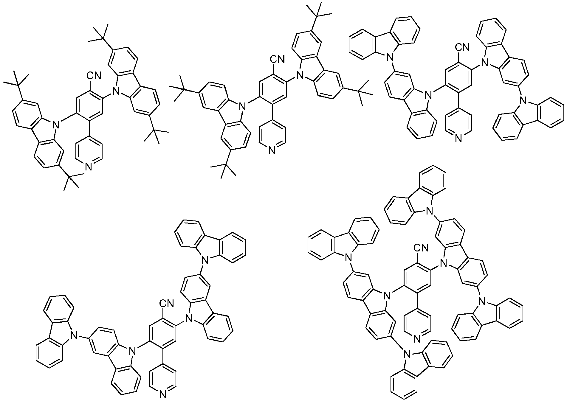


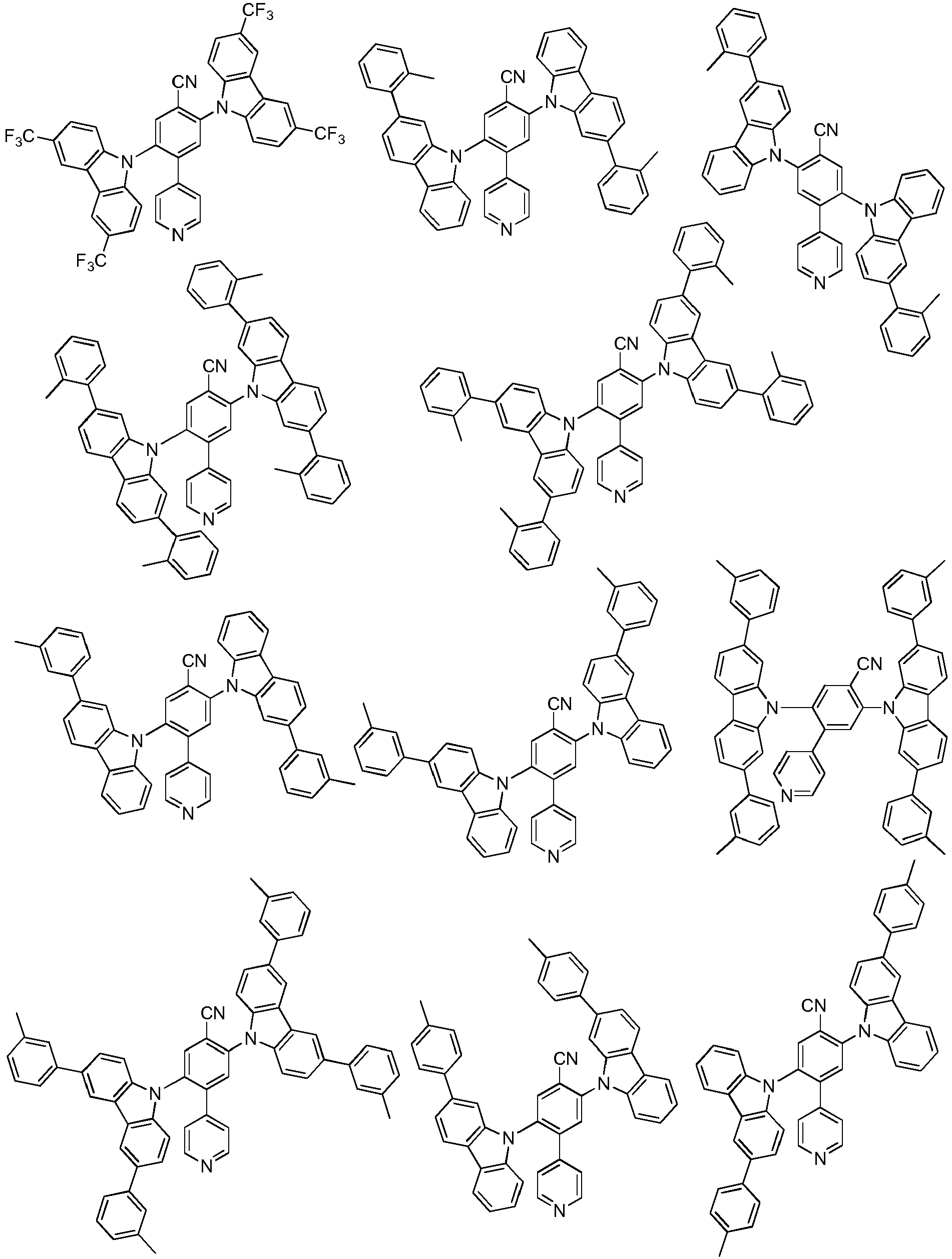


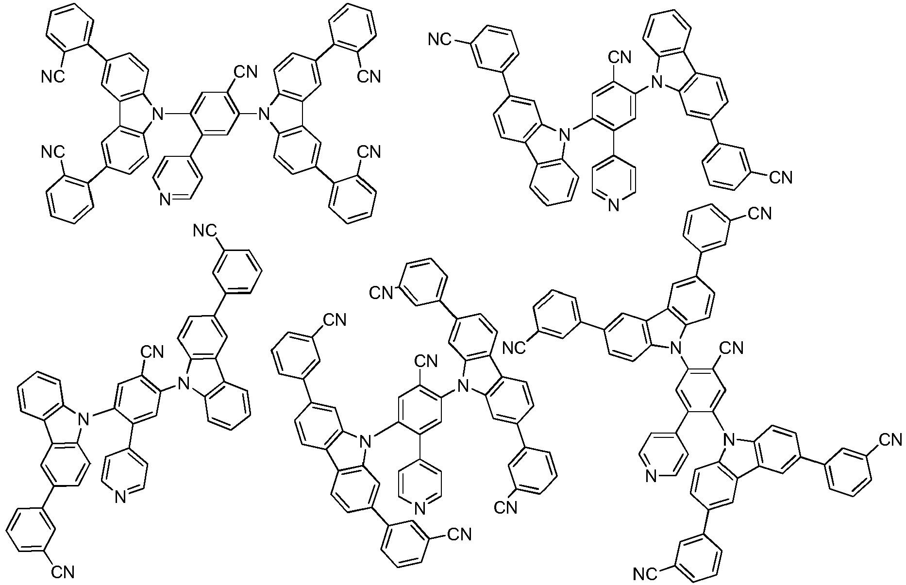


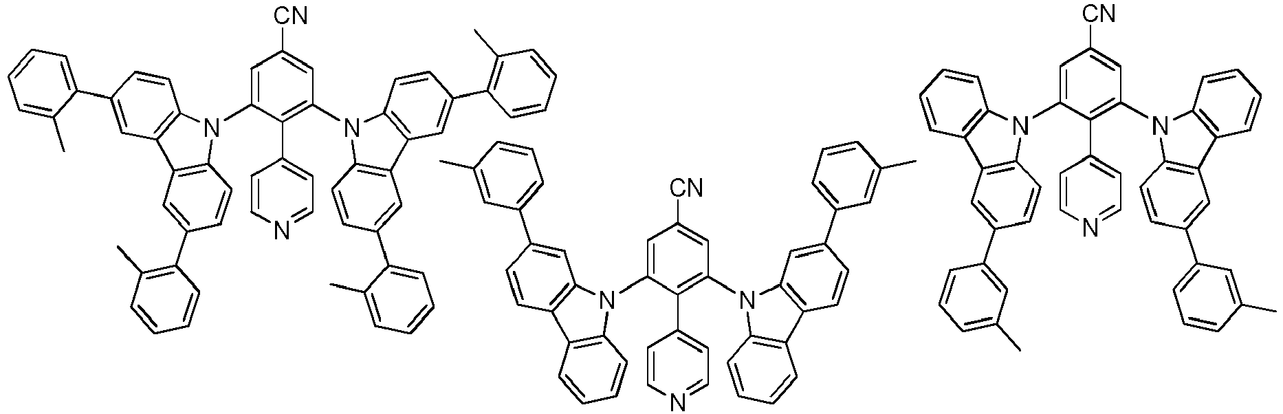


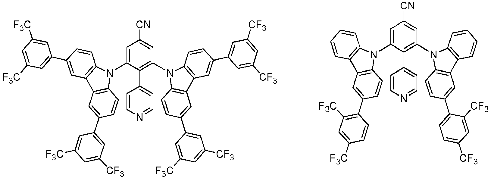


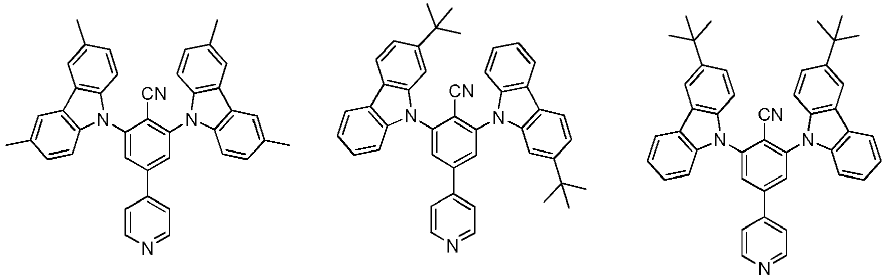


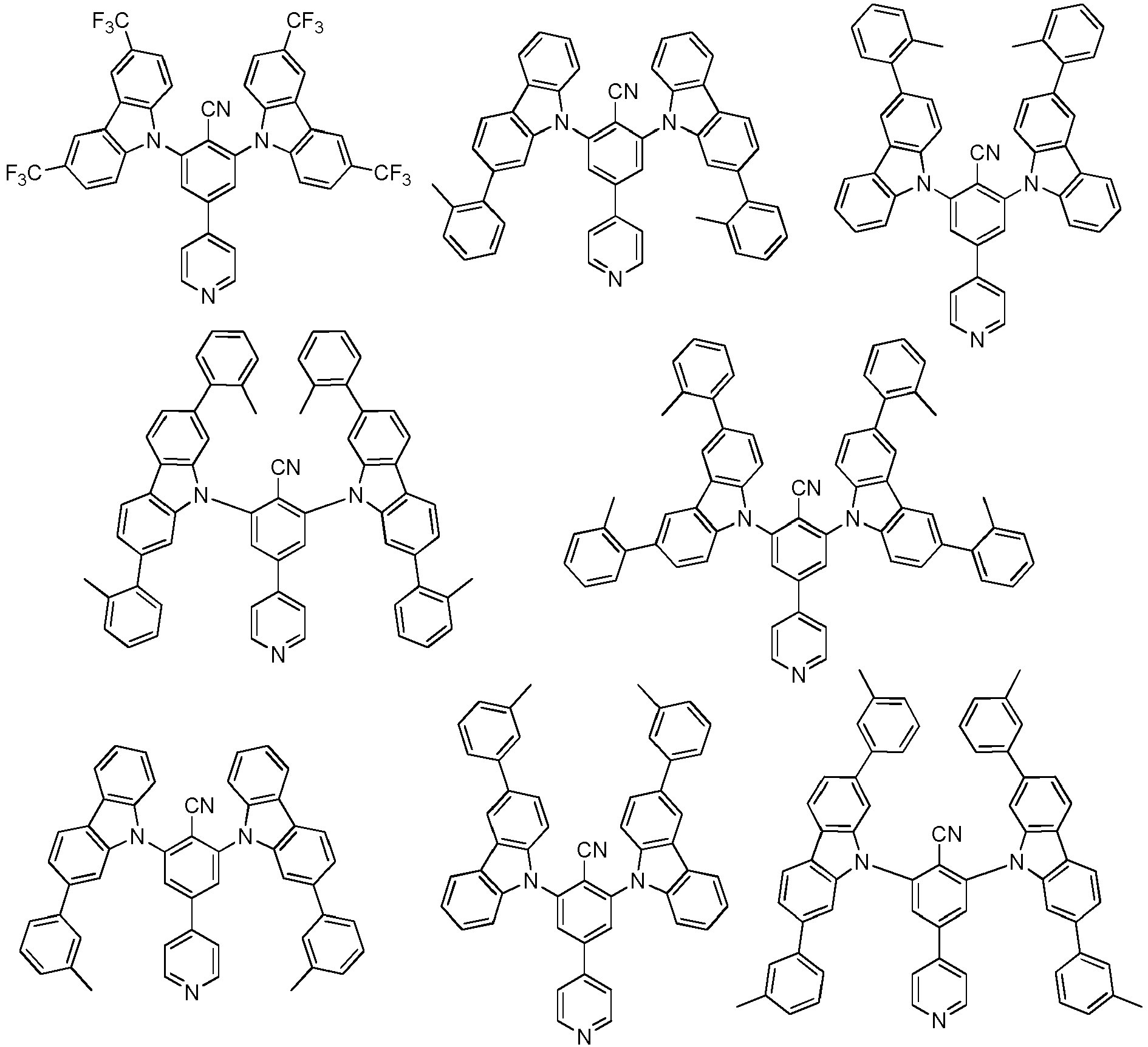


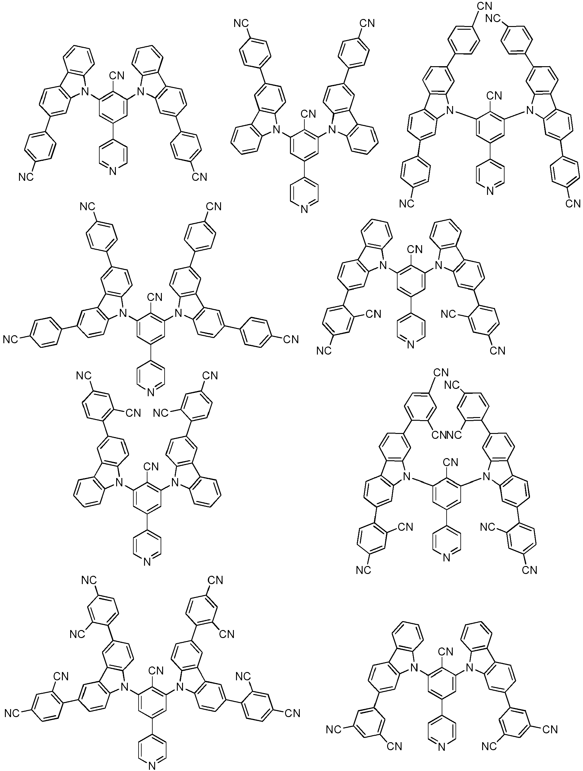

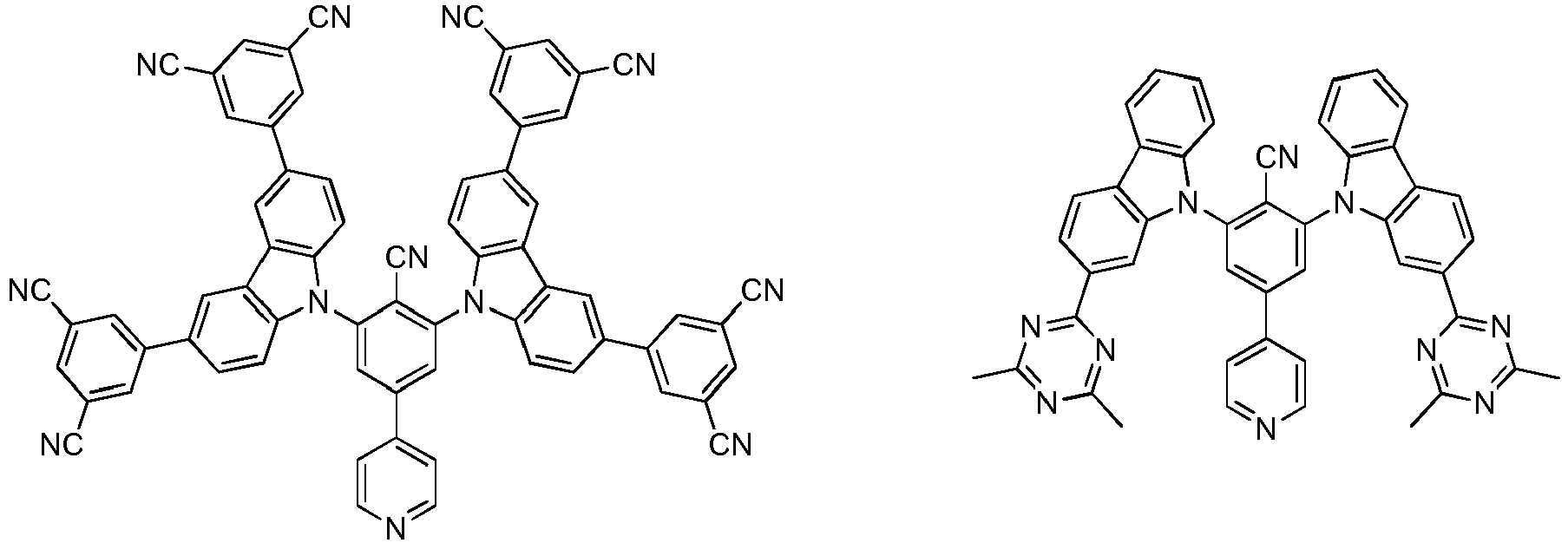


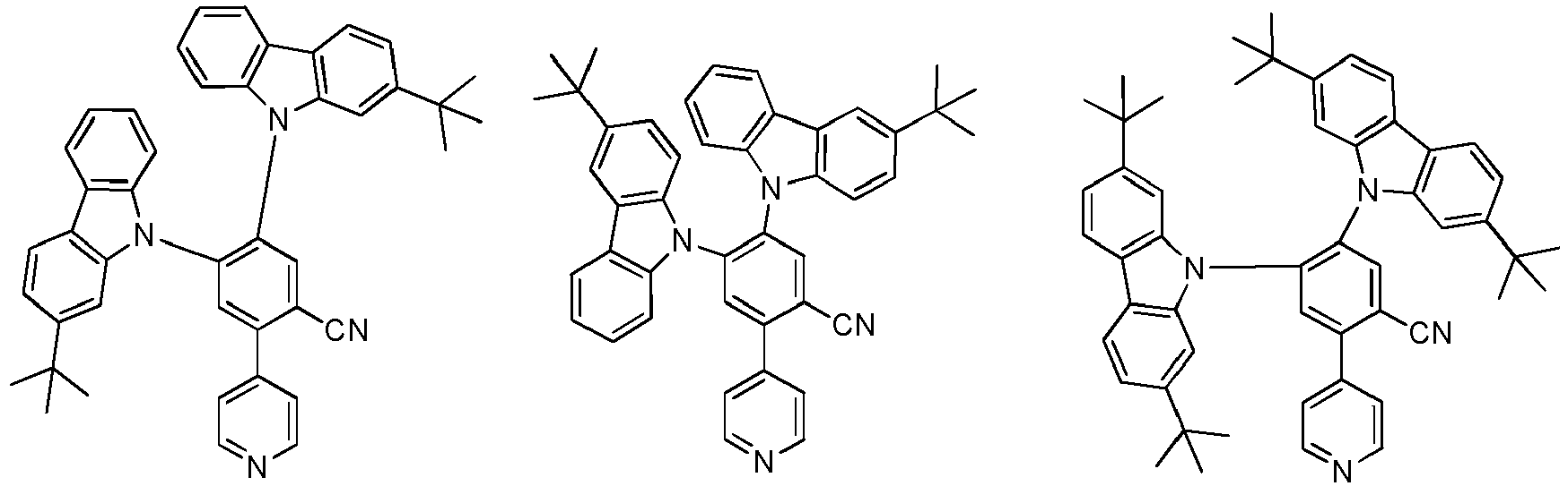

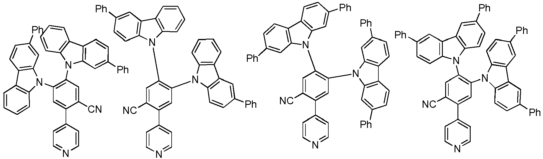


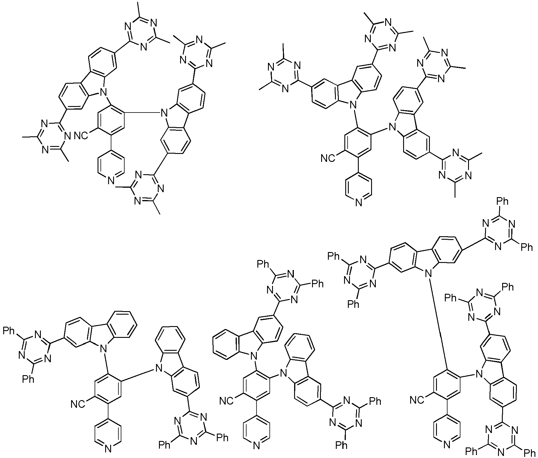
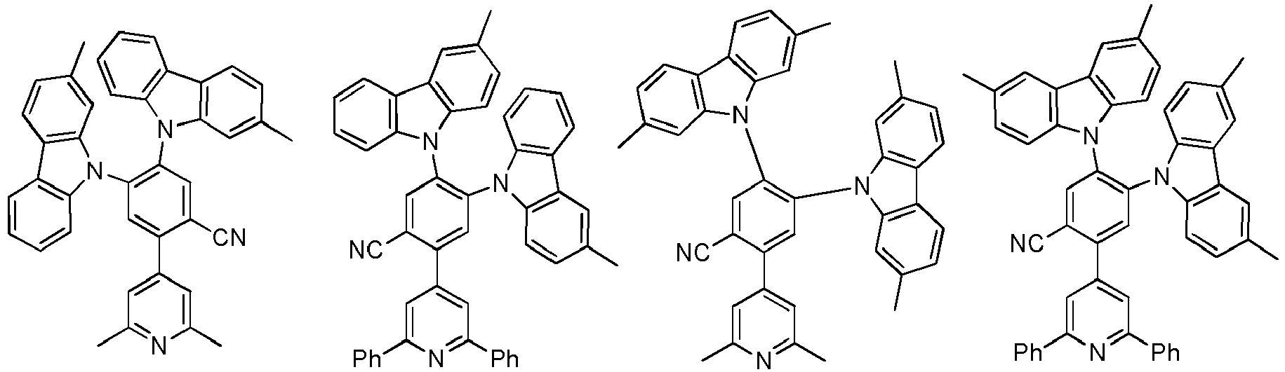


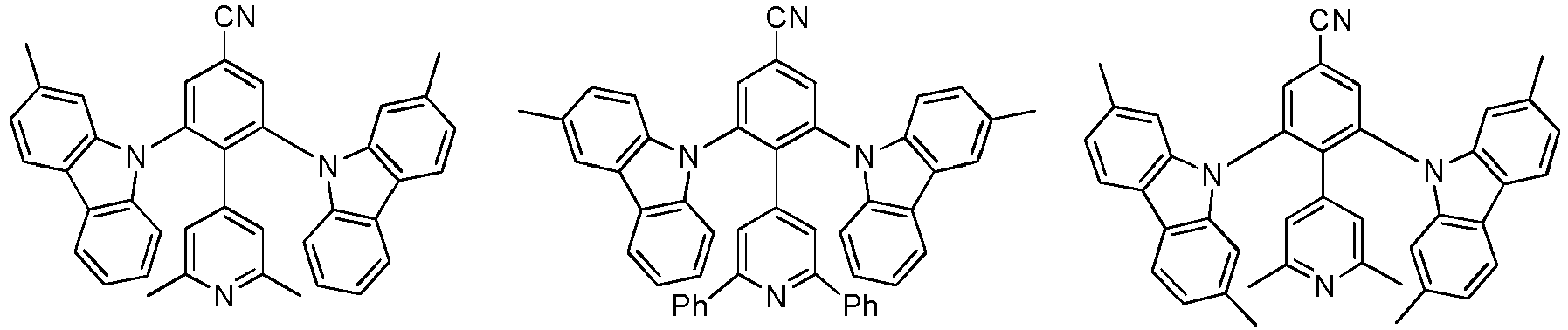


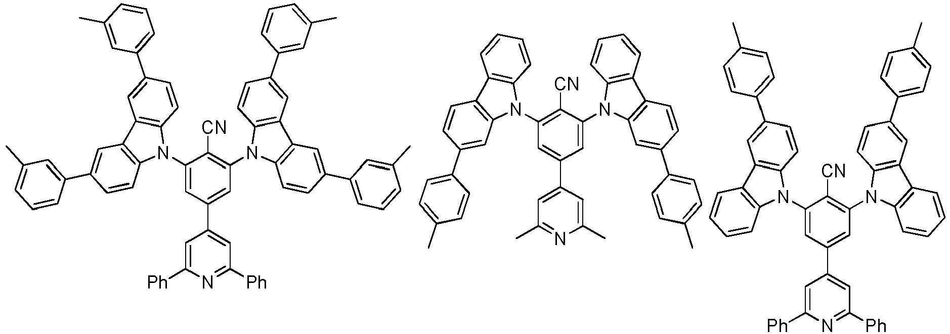


- Es zeigen:
- Figur 1
- Emissionsspektrum von Beispiel 1 (10 % in PMMA).
- Figur 2
- Emissionsspektrum von Beispiel 2 (10 % in PMMA).
- Figur 3
- Emissionsspektrum von Beispiel 3 (10 % in PMMA).
- Figur 4
- Emissionsspektrum von Beispiel 4 (10 % in PMMA).
- Figur 5
- Emissionsspektrum von Beispiel 5 (10 % in PMMA).
- Figur 6
- Emissionsspektrum von Beispiel 6 (10 % in PMMA).
- Figur 7
- Emissionsspektrum von Beispiel 7 (10 % in PMMA).
- Figur 8
- Emissionsspektrum von Beispiel 8 (10 % in PMMA).
- Figur 9
- Emissionsspektrum von Beispiel 9 (10 % in PMMA).
- Figur 10
- Emissionsspektrum von Beispiel 10 (10 % in PMMA).
- Figur 11
- Emissionsspektrum von Beispiel 11 (10 % in PMMA).
- Figur 12
- Emissionsspektrum von Beispiel 12 (10 % in PMMA).
- Figur 13
- Emissionsspektrum von Beispiel 13 (10 % in PMMA).
- Figur 14
- Emissionsspektrum von Beispiel 14 (10 % in PMMA).
- Figur 15
- Emissionsspektrum von Beispiel 15 (10 % in PMMA).
- Figur 16
- Emissionsspektrum von Beispiel 16 (10 % in PMMA).
- Figur 17
- Emissionsspektrum von Beispiel 17 (10 % in PMMA).
- Figur 18
- Emissionsspektrum von Beispiel 18 (10 % in PMMA).
- Figur 19
- Emissionsspektrum von Beispiel 19 (10 % in PMMA).
- Figur 20
- Emissionsspektrum von Beispiel 20 (10 % in PMMA).
- Figur 21
- Emissionsspektrum von Beispiel 21 (10% in PMMA).
- Figur 22
- Emissionsspektrum von Beispiel 22 (10 % in PMMA).
- Figur 23
- Emissionsspektrum von Beispiel 23 (10 % in PMMA).
- Figur 24
- Emissionsspektrum von Beispiel 24 (10 % in PMMA).
- Figur 25
- Emissionsspektrum von Beispiel 25 (10 % in PMMA).
- Figur 26
- Emissionsspektrum von Beispiel 26 (10 % in PMMA).
- Figur 27
- Emissionsspektrum von Beispiel 27 (10 % in PMMA).
- Figur 28
- Emissionsspektrum von Beispiel 28 (10 % in PMMA).
- Figur 29
- Emissionsspektrum von Beispiel 29 (10 % in PMMA).
- Figur 30
- Emissionsspektrum von Beispiel 30 (10 % in PMMA).
- Figur 31
- Emissionsspektrum von Beispiel 31 (10 % in PMMA).
- Figur 32
- Emissionsspektrum von Beispiel 32 (10 % in PMMA).
- Figur 33
- Emissionsspektrum von Beispiel 33 (10 % in PMMA).
- Figur 34
- Emissionsspektrum von Beispiel 34 (10 % in PMMA).
- Figur 35
- Emissionsspektrum von Beispiel 35 (10 % in PMMA).
- Figur 36
- Emissionsspektrum von Beispiel 36 (10 % in PMMA).
- Figur 37
- Emissionsspektrum von Beispiel 37 (10 % in PMMA).
- Figur 38
- Emissionsspektrum von Beispiel 38 (10 % in PMMA).
- Figur 39
- Emissionsspektrum von Beispiel 39 (10 % in PMMA).
- Figur 40
- Emissionsspektrum von Beispiel 40 (10 % in PMMA).
- Figur 41
- Emissionsspektrum von Beispiel 41 (10 % in PMMA).
- Figur 42
- Emissionsspektrum von Beispiel 42 (10 % in PMMA).
- Figur 43
- Emissionsspektrum von Beispiel 43 (10 % in PMMA).
- Figur 44
- Emissionsspektrum von Beispiel 44 (10 % in PMMA).
- Figur 45
- Emissionsspektrum von Beispiel 45 (10 % in PMMA).
Claims (14)
- Organisches Molekül, aufweisend- eine erste chemische Einheit aufweisend eine oder bestehend aus einer Struktur gemäß Formel I
 - zwei zweite chemische Einheiten D, jeweils bei jedem Auftreten gleich oder verschieden, aufweisend eine oder bestehend aus einer Struktur gemäß Formel II,wobei jeder der Reste Ra, R3, R4 oder R5 auch mit einem oder mehreren weiteren Resten Ra, R3, R4 oder R5 ein mono- oder polycyclisches, aliphatisches, aromatisches und/oder benzoanelliertes Ringsystem bilden kann;
mitT ist Anknüpfungspunkt der Einfachbindung zwischen der ersten chemischen Einheit und einer chemischen Einheit D oder ist H;V ist Anknüpfungspunkt der Einfachbindung zwischen der ersten chemischen Einheit und einer chemischen Einheit D oder ist H;W ist Anknüpfungspunkt der Einfachbindung zwischen der ersten chemischen Einheit und einer chemischen Einheit D oder ist ausgewählt aus der Gruppe bestehend aus H, CN und CF3;X ist Anknüpfungspunkt der Einfachbindung zwischen der ersten chemischen Einheit und einer chemischen Einheit D oder ist ausgewählt aus der Gruppe bestehend aus H, CN und CF3;Y ist Anknüpfungspunkt der Einfachbindung zwischen der ersten chemischen Einheit und einer chemischen Einheit D oder ist ausgewählt aus der Gruppe bestehend aus H, CN und CF3;# kennzeichnet den Anknüpfungspunkt der Einfachbindung zwischen einer chemischen Einheit D und der ersten chemischen Einheit;Z ist bei jedem Auftreten gleich oder verschieden eine direkte Bindung oder ausgewählt aus der Gruppe bestehend aus CR3R4, C=CR3R4, C=O, C=NR3, NR3, O, SiR3R4, S, S(O) und S(O)2;R1 und R2 ist bei jedem Auftreten gleich oder verschieden bei jedem Auftreten gleich oder verschieden ausgewählt aus der Gruppe bestehend aus:- H, Deuterium;- einer linearen Alkylgruppe mit 1 bis 5 C-Atomen, einer linearen Alkenyl- oder Alkinylgruppe mit 2 bis 8 C-Atomen, einer verzweigten oder cyclischen Alkyl-, Alkenyl- oder Alkinylgruppe mit 3 bis 10 C-Atomen, wobei ein oder mehrere H-Atome durch Deuterium ersetzt sein können; und- einem aromatischen oder heteroaromatischen Ringsystem mit 5 bis 15 aromatischen Ringatomen, das jeweils mit einem oder mehreren Reste R6 substituiert sein kann;Ra, R3 und R4 ist bei jedem Auftreten gleich oder verschieden ausgewählt aus der Gruppe bestehend aus:- H, Deuterium, N(R5)2, OH, Si(R5)3, B(OR5)2, OSO2R5, CF3, CN, F, Br, I;- einer linearen Alkyl-, Alkoxy- oder Thioalkoxygruppe mit 1 bis 40 C-Atomen, die jeweils mit einem oder mehreren Resten R5 substituiert sein kann, wobei eine oder mehrere nicht benachbarte CH2-Gruppen durch R5C=CR5, C=C, Si(R5)2, Ge(R5)2, Sn(R5)2, C=O, C=S, C=Se, C=NR5, P(=O)(R5), SO, SO2, NR5, O, S oder CONR5 ersetzt sein können und wobei ein oder mehrere H-Atome durch Deuterium, CN, CF3 oder NO2 ersetzt sein können;- einer linearen Alkenyl- oder Alkinylgruppe mit 2 bis 40 C-Atomen, die jeweils mit einem oder mehreren Resten R5 substituiert sein kann, wobei eine oder mehrere nicht benachbarte CH2-Gruppen durch R5C=CR5, C=C, Si(R5)2, Ge(R5)2, Sn(R5)2, C=O, C=S, C=Se, C=NR5, P(=O)(R5), SO, SO2, NR5, O, S oder CONR5 ersetzt sein können und wobei ein oder mehrere H-Atome durch Deuterium, CN, CF3 oder NO2 ersetzt sein können;- einer verzweigten oder cyclischen Alkyl-, Alkenyl-, Alkinyl-, Alkoxy- oder Thioalkoxygruppe mit 3 bis 40 C-Atomen, die jeweils mit einem oder mehreren Resten R5 substituiert sein kann, wobei eine oder mehrere nicht benachbarte CH2-Gruppen durch R5C=CR5, C≡C, Si(R5)2, Ge(R5)2, Sn(R5)2, C=O, C=S, C=Se, C=NR5, P(=O)(R5), SO, SO2, NR5, O, S oder CONR5 ersetzt sein können und wobei ein oder mehrere H-Atome durch Deuterium, CN, CF3 oder NO2 ersetzt sein können;- einem aromatischen oder heteroaromatischen Ringsystem mit 5 bis 60 aromatischen Ringatomen, das jeweils mit einem oder mehreren Resten R5 substituiert sein kann;- einer Aryloxy- oder Heteroaryloxygruppe mit 5 bis 60 aromatischen Ringatomen, die jeweils mit einem oder mehreren Resten R5 substituiert sein kann; und- eine Diarylaminogruppe, Diheteroarylaminogruppe oder Arylheteroarylaminogruppe mit 10 bis 40 aromatischen Ringatomen, welche jeweils mit einem oder mehreren Resten R5 substituiert sein kann;R5 ist bei jedem Auftreten gleich oder verschieden ausgewählt aus der Gruppe bestehend aus:- H, Deuterium, N(R6)2, OH, Si(R6)3, B(OR6)2, OSO2R6, CF3, CN, F, Br, I;- einer linearen Alkyl-, Alkoxy- oder Thioalkoxygruppe mit 1 bis 40 C-Atomen,die jeweils mit einem oder mehreren Resten R6 substituiert sein kann, wobei eine oder mehrere nicht benachbarte CH2-Gruppen durch R6C=CR6, C=C, Si(R6)2, Ge(R6)2, Sn(R6)2, C=O, C=S, C=Se, C=NR6, P(=O)(R6), SO, SO2, NR6, O, S oder CONR6 ersetzt sein können und wobei ein oder mehrere H-Atome durch Deuterium, CN, CF3 oder NO2 ersetzt sein können;- einer linearen Alkenyl- oder Alkinylgruppe mit 2 bis 40 C-Atomen, die jeweils mit einem oder mehreren Resten R6 substituiert sein kann, wobei eine oder mehrere nicht benachbarte CH2-Gruppen durch R6C=CR6, C≡C, Si(R6)2, Ge(R6)2, Sn(R6)2, C=O, C=S, C=Se, C=NR6, P(=O)(R6), SO, SO2, NR6, O, S oder CONR6 ersetzt sein können und wobei ein oder mehrere H-Atome durch Deuterium, CN, CF3 oder NO2 ersetzt sein können;- einer verzweigten oder cyclischen Alkyl-, Alkenyl-, Alkinyl-, Alkoxy- oder Thioalkoxygruppe mit 3 bis 40 C-Atomen, die jeweils mit einem oder mehreren Resten R6 substituiert sein kann, wobei eine oder mehrere nicht benachbarte CH2-Gruppen durch R6C=CR6, C≡C, Si(R6)2, Ge(R6)2, Sn(R6)2, C=O, C=S, C=Se, C=NR6, P(=O)(R6), SO, SO2, NR6, O, S oder CONR6 ersetzt sein können und wobei ein oder mehrere H-Atome durch Deuterium, CN, CF3 oder NO2 ersetzt sein können;- einem aromatischen oder heteroaromatischen Ringsystem mit 5 bis 60 aromatischen Ringatomen, das jeweils mit einem oder mehreren Resten R6 substituiert sein kann,- einer Aryloxy- oder Heteroaryloxygruppe mit 5 bis 60 aromatischen Ringatomen, die jeweils mit einem oder mehreren Resten R6 substituiert sein kann; und- einer Diarylaminogruppe, Diheteroarylaminogruppe oder Arylheteroarylaminogruppe mit 10 bis 40 aromatischen Ringatomen, welche jeweils mit einem oder mehreren Resten R6 substituiert sein kann;R6 ist bei jedem Auftreten gleich oder verschieden ausgewählt aus der Gruppe bestehend aus:- H, Deuterium, OH, CF3, CN, F;- einer linearen Alkyl-, Alkoxy- oder Thioalkoxygruppe mit 1 bis 5 C-Atomen, wobei ein oder mehrere H-Atome durch Deuterium, CN, CF3 oder NO2 ersetzt sein können;- einer linearen Alkenyl- oder Alkinylgruppe mit 2 bis 5 C-Atomen, wobei ein oder mehrere H-Atome durch Deuterium, CN, CF3 oder NO2 ersetzt sein können;- einer verzweigten oder cyclischen Alkyl-, Alkenyl-, Alkinyl-, Alkoxy- oder Thioalkoxygruppe mit 3 bis 5 C-Atomen, wobei ein oder mehrere H-Atome durch Deuterium, CN, CF3 oder NO2 ersetzt sein können;- einem aromatischen oder heteroaromatischen Ringsystem mit 5 bis 60 aromatischen Ringatomen;- einer Aryloxy- oder Heteroaryloxygruppe mit 5 bis 60 aromatischen Ringatomen; und- einer Diarylaminogruppe, Diheteroarylaminogruppe oder Arylheteroarylaminogruppe mit 10 bis 40 aromatischen Ringatomen;
wobei
genau ein Rest ausgewählt aus der Gruppe bestehend aus W, X und Y gleich CN oder CF3 ist und genau zwei Reste ausgewählt aus der Gruppe bestehend aus T, V, W, X und Y gleich einem Anknüpfungspunkt der Einfachbindung zwischen der ersten chemischen Einheit und einer chemischen Einheit D sind. - Organisches Molekül nach Anspruch 1, wobei R1 und R2 bei jedem Auftreten gleich oder verschieden gleich H, Methyl oder Phenyl ist.
- Organisches Molekül nach Anspruch 1 oder 2, wobei W gleich CN ist.
- Organisches Molekül nach Anspruch 1 bis 3, wobei die zweite chemische Einheit D bei jedem Auftreten gleich oder verschieden eine Struktur der Formel IIa aufweist oder aus einer Struktur der Formel IIa besteht:

- Organisches Molekül nach Anspruch 1 bis 4, wobei die zweite chemische Einheit D jeweils eine Struktur der Formel IIb aufweist oder aus einer Struktur der Formel IIb besteht:
 Rb bei jedem Auftreten gleich oder verschieden ausgewählt ist aus der Gruppe bestehend aus:- N(R5)2, OH, Si(R5)3, B(OR5)2, OSO2R5, CF3, CN, F, Br, I;- einer linearen Alkyl-, Alkoxy- oder Thioalkoxygruppe mit 1 bis 40 C-Atomen, die jeweils mit einem oder mehreren Resten R5 substituiert sein kann, wobei eine oder mehrere nicht benachbarte CH2-Gruppen durch R5C=CR5, C=C, Si(R5)2, Ge(R5)2, Sn(R5)2, C=O, C=S, C=Se, C=NR5, P(=O)(R5), SO, SO2, NR5, O, S oder CONR5 ersetzt sein können und wobei ein oder mehrere H-Atome durch Deuterium, CN, CF3 oder NO2 ersetzt sein können;- einer linearen Alkenyl- oder Alkinylgruppe mit 2 bis 40 C-Atomen, die jeweils mit einem oder mehreren Resten R5 substituiert sein kann, wobei eine oder mehrere nicht benachbarte CH2-Gruppen durch R5C=CR5, C=C, Si(R5)2, Ge(R5)2, Sn(R5)2, C=O, C=S, C=Se, C=NR5, P(=O)(R5), SO, SO2, NR5, O, S oder CONR5 ersetzt sein können und wobei ein oder mehrere H-Atome durch Deuterium, CN, CF3 oder NO2 ersetzt sein können;- einer verzweigten oder cyclischen Alkyl-, Alkenyl-, Alkinyl-, Alkoxy- oder Thioalkoxygruppe mit 3 bis 40 C-Atomen, die jeweils mit einem oder mehreren Resten R5 substituiert sein kann, wobei eine oder mehrere nicht benachbarte CH2-Gruppen durch R5C=CR5, C≡C, Si(R5)2, Ge(R5)2, Sn(R5)2, C=O, C=S, C=Se, C=NR5, P(=O)(R5), SO, SO2, NR5, O, S oder CONR5 ersetzt sein können und wobei ein oder mehrere H-Atome durch Deuterium, CN, CF3 oder NO2 ersetzt sein können;- einem aromatischem oder heteroaromatischem Ringsystem mit 5 bis 60 aromatischen Ringatomen, das jeweils mit einem oder mehreren Resten R5 substituiert sein kann;- einer Aryloxy- oder Heteroaryloxygruppe mit 5 bis 60 aromatischen Ringatomen, die jeweils mit einem oder mehreren Resten R5 substituiert sein kann; und- einer Diarylaminogruppe, Diheteroarylaminogruppe oder Arylheteroarylaminogruppe mit 10 bis 40 aromatischen Ringatomen, welche jeweils mit einem oder mehreren Resten R5 substituiert sein kann;und für # und R5 die in Anspruch 1 genannten Definitionen gelten.
 - Organisches Molekül nach Anspruch 1 bis 4, wobei die zweite chemische Einheit D jeweils eine Struktur der Formel IIc aufweist oder aus einer Struktur der Formel IIc besteht:
 Rb bei jedem Auftreten gleich oder verschieden ausgewählt ist aus der Gruppe bestehend aus:- N(R5)2, OH, Si(R5)3, B(OR5)2, OSO2R5, CF3, CN, F, Br, I;- einer linearen Alkyl-, Alkoxy- oder Thioalkoxygruppe mit 1 bis 40 C-Atomen, die jeweils mit einem oder mehreren Resten R5 substituiert sein kann, wobei eine oder mehrere nicht benachbarte CH2-Gruppen durch R5C=CR5, C=C, Si(R5)2, Ge(R5)2, Sn(R5)2, C=O, C=S, C=Se, C=NR5, P(=O)(R5), SO, SO2, NR5, O, S oder CONR5 ersetzt sein können und wobei ein oder mehrere H-Atome durch Deuterium, CN, CF3 oder NO2 ersetzt sein können;- einer linearen Alkenyl- oder Alkinylgruppe mit 2 bis 40 C-Atomen, die jeweils mit einem oder mehreren Resten R5 substituiert sein kann, wobei eine oder mehrere nicht benachbarte CH2-Gruppen durch R5C=CR5, C=C, Si(R5)2, Ge(R5)2, Sn(R5)2, C=O, C=S, C=Se, C=NR5, P(=O)(R5), SO, SO2, NR5, O, S oder CONR5 ersetzt sein können und wobei ein oder mehrere H-Atome durch Deuterium, CN, CF3 oder NO2 ersetzt sein können;- einer verzweigten oder cyclischen Alkyl-, Alkenyl-, Alkinyl-, Alkoxy- oder Thioalkoxygruppe mit 3 bis 40 C-Atomen, die jeweils mit einem oder mehreren Resten R5 substituiert sein kann, wobei eine oder mehrere nicht benachbarte CH2-Gruppen durch R5C=CR5, C≡C, Si(R5)2, Ge(R5)2, Sn(R5)2, C=O, C=S, C=Se, C=NR5, P(=O)(R5), SO, SO2, NR5, O, S oder CONR5 ersetzt sein können und wobei ein oder mehrere H-Atome durch Deuterium, CN, CF3 oder NO2 ersetzt sein können;- einem aromatischen oder heteroaromatischen Ringsystem mit 5 bis 60 aromatischen Ringatomen, das jeweils mit einem oder mehreren Resten R5 substituiert sein kann;- einer Aryloxy- oder Heteroaryloxygruppe mit 5 bis 60 aromatischen Ringatomen, die jeweils mit einem oder mehreren Resten R5 substituiert sein kann; und- einer Diarylaminogruppe, Diheteroarylaminogruppe oder Arylheteroarylaminogruppe mit 10 bis 40 aromatischen Ringatomen, welche jeweils mit einem oder mehreren Resten R5 substituiert sein kann;und im Übrigen die in Anspruch 1 genannte Definitionen gelten.
 - Organisches Molekül nach Anspruch 5 oder 6, wobei Rb bei jedem Auftreten gleich oder verschieden Me, iPr, tBu, CN, CF3 oder Ph, das jeweils mit einem oder mehreren Resten ausgewählt aus Me, iPr, tBu, CN, CF3 oder Ph substituiert sein kann, Pyridinyl, das jeweils mit einem oder mehreren Resten ausgewählt aus Me, iPr, tBu, CN, CF3 oder Ph substituiert sein kann, Pyrimidinyl, das jeweils mit einem oder mehreren Resten ausgewählt aus Me, iPr, tBu, CN, CF3 oder Ph substituiert sein kann, Triazinyl, das jeweils mit einem oder mehreren Resten ausgewählt aus Me, iPr, tBu, CN, CF3 oder Ph substituiert sein kann, Carbazolyl, das jeweils mit einem oder mehreren Resten ausgewählt aus Me, iPr, tBu, CN, CF3 oder Ph substituiert sein kann, oder N(Ph)2 ist.
- Verfahren zur Herstellung eines Organischen Moleküls nach Anspruch 1 bis 7, wobei eine in 3,5-Position R1-substituierte und in 2,6-Position R2-substituierte 4-Pyridinboronsäure oder ein in 3,5-Position R1-substituierter und in 2,6-Position R2-substituierter 4-Pyridinboronsäureester als Edukt eingesetzt wird.
- Verwendung eines organischen Moleküls nach Anspruch 1 bis 7 als lumineszierender Emitter und/oder als Hostmaterial und/oder als Elektronentransportmaterial und/oder als Lochinjektionsmaterial und/oder als Lochblockiermaterial in einer organischen optoelektronischen Vorrichtung.
- Verwendung nach Anspruch 9, wobei die organische optoelektronische Vorrichtung ausgewählt ist aus der Gruppe bestehend aus:• organischen lichtemittierenden Dioden (OLEDs),• lichtemittierenden elektrochemischen Zellen,• OLED-Sensoren, insbesondere in nicht hermetisch nach außen abgeschirmten Gas- und Dampf-Sensoren,• organischen Dioden,• organischen Solarzellen,• organischen Transistoren,• organischen Feldeffekttransistoren,• organischen Lasern und• Down-Konversions-Elementen.
- Zusammensetzung aufweisend oder bestehend aus:(a) mindestens einem organischen Molekül nach einem der Ansprüche 1 bis 7, insbesondere in Form eines Emitters und/oder Hosts, und(b) einem oder mehrerer Emitter- und/oder Hostmaterialien, die von dem Molekül nach Anspruch 1 bis 7 verschiedenen sind und(c) optional einem oder mehreren Farbstoffen und/ oder einem oder mehreren Lösungsmitteln.
- Organische optoelektronische Vorrichtung, aufweisend ein organisches Molekül nach Anspruch 1 bis 7 oder eine Zusammensetzung nach Anspruch 11, insbesondere ausgeformt als eine Vorrichtung ausgewählt aus der Gruppe bestehend aus organischer lichtemittierender Diode (OLED), lichtemittierender elektrochemischer Zelle, OLED-Sensor, insbesondere nicht hermetisch nach außen abgeschirmten Gas- und Dampf-Sensoren, organischer Diode, organischer Solarzelle, organischem Transistor, organischem Feldeffekttransistor, organischem Laser und Down-Konversion-Element.
- Organische optoelektronische Vorrichtung nach Anspruch 12, aufweisend- ein Substrat,- eine Anode und- eine Kathode, wobei die Anode oder die Kathode auf das Substrat aufgebracht sind, und- mindestens eine lichtemittierende Schicht, die zwischen Anode und Kathode angeordnet ist und die ein organisches Molekül nach Anspruch 1 bis 7 oder eine Zusammensetzung nach Anspruch 11 aufweist.
- Verfahren zur Herstellung eines optoelektronischen Bauelements, wobei ein organisches Molekül nach Anspruch 1 bis 7 verwendet wird, insbesondere umfassend die Verarbeitung des organischen Moleküls mittels eines Vakuumverdampfungsverfahrens oder aus einer Lösung.
Applications Claiming Priority (4)
| Application Number | Priority Date | Filing Date | Title |
|---|---|---|---|
| DE102016115728.7A DE102016115728B4 (de) | 2016-08-24 | 2016-08-24 | Organische Moleküle, insbesondere zur Verwendung in organischen optoelektronischen Vorrichtungen |
| DE102016119937 | 2016-10-19 | ||
| DE102017103939 | 2017-02-24 | ||
| DE102017106221 | 2017-03-22 |
Publications (2)
| Publication Number | Publication Date |
|---|---|
| EP3287451A1 EP3287451A1 (de) | 2018-02-28 |
| EP3287451B1 true EP3287451B1 (de) | 2019-12-11 |
Family
ID=59702568
Family Applications (1)
| Application Number | Title | Priority Date | Filing Date |
|---|---|---|---|
| EP17187665.9A Active EP3287451B1 (de) | 2016-08-24 | 2017-08-24 | Organische moleküle, insbesondere zur verwendung in organischen optoelektronischen vorrichtungen |
Country Status (6)
| Country | Link |
|---|---|
| US (2) | US10665792B2 (de) |
| EP (1) | EP3287451B1 (de) |
| JP (1) | JP6789195B2 (de) |
| KR (1) | KR102207689B1 (de) |
| CN (1) | CN107778294B (de) |
| TW (1) | TWI705061B (de) |
Families Citing this family (19)
| Publication number | Priority date | Publication date | Assignee | Title |
|---|---|---|---|---|
| EP3511321B1 (de) | 2016-09-09 | 2021-11-03 | Toyobo Co., Ltd. | Organisches lichtemittierendes element und lichtemittierendes material sowie darin verwendete verbindung |
| EP3398945B1 (de) * | 2017-05-04 | 2022-11-02 | Samsung Display Co., Ltd. | Pyrimidinyl-derivate zur verwendung in opto-elektronischen vorrichtungen |
| EP3645524B1 (de) * | 2017-06-28 | 2021-11-24 | cynora GmbH | Organische moleküle, insbesondere zur verwendung in optoelektronischen vorrichtungen |
| EP3645522B1 (de) * | 2017-06-29 | 2021-10-13 | cynora GmbH | Organische moleküle, insbesondere zur verwendung in optoelektronischen vorrichtungen |
| JP7165943B2 (ja) * | 2017-11-01 | 2022-11-07 | 東洋紡株式会社 | π電子共役単位とカルバゾール基を有する化合物 |
| KR102599981B1 (ko) * | 2018-03-22 | 2023-11-10 | 삼성디스플레이 주식회사 | 유기 전계 발광 소자 및 유기 전계 발광 소자용 다환 화합물 |
| DE102018108793A1 (de) * | 2018-04-13 | 2019-10-17 | Cynora Gmbh | Organische Moleküle, insbesondere zur Verwendung in optoelektronischen Vorrichtungen |
| CN110407810B (zh) * | 2018-04-27 | 2023-11-24 | 北京鼎材科技有限公司 | 一种有机电致发光材料及其应用 |
| WO2019224006A1 (en) * | 2018-05-22 | 2019-11-28 | Cynora Gmbh | Carbazole-pyridine-cyanophenyl derivatives and related compounds for use as luminescent emitters in oleds |
| EP3581570B1 (de) * | 2018-06-15 | 2021-04-21 | Cynora Gmbh | Carbazole-pyridine-trifluoromethylphenyl derivate und ähnliche verbindungen zur verwendung als tadf lumineszenzemitter in oleds |
| EP3813764A2 (de) | 2018-06-29 | 2021-05-05 | 3M Innovative Properties Company | Unter verwendung eines polycarbonatdiols hergestellte kieferorthopädische artikel, polymerisierbare zusammensetzungen und verfahren zur herstellung der artikel |
| WO2020003197A2 (en) | 2018-06-29 | 2020-01-02 | 3M Innovative Properties Company | Orthodontic articles prepared using a polycarbonate diol, polymerizable compositions, and methods of making the articles |
| US20210305517A1 (en) * | 2018-10-09 | 2021-09-30 | Kyulux, Inc. | Composition of matter for use in organic light-emitting diodes |
| EP3640999B1 (de) | 2018-10-15 | 2022-01-05 | cynora GmbH | Blaulichtemittierende organische elektrolumineszente vorrichtung |
| CN109734928B (zh) * | 2019-01-04 | 2021-08-17 | 中国科学院长春应用化学研究所 | 一种空间电荷转移树枝状荧光材料及其制备方法、有机电致发光器件 |
| CN109585668B (zh) * | 2019-01-10 | 2021-01-29 | 京东方科技集团股份有限公司 | Oled显示器件、显示面板、oled显示器件的制备方法 |
| JP7456125B2 (ja) | 2019-11-11 | 2024-03-27 | 東洋紡株式会社 | パーフルオロアルキル基を有する含窒素複素環化合物及びその利用 |
| KR102361170B1 (ko) * | 2020-02-12 | 2022-02-09 | 단국대학교 천안캠퍼스 산학협력단 | 피리딘을 포함하는 오르토터페닐 구조의 화합물 및 이를 함유하는 유기발광다이오드 |
| JPWO2021241677A1 (de) * | 2020-05-29 | 2021-12-02 |
Family Cites Families (18)
| Publication number | Priority date | Publication date | Assignee | Title |
|---|---|---|---|---|
| PL355851A1 (en) * | 1999-12-08 | 2004-05-31 | Gentian As | Substituted phthalocyanines and their precursors |
| EP2169028B1 (de) | 2002-03-22 | 2018-11-21 | Idemitsu Kosan Co., Ltd. | Material für organische Elektrolumineszenzvorrichtungen und daraus hergestellte organische Elektrolumineszenzvorrichtungen |
| EP1724323A4 (de) * | 2004-03-08 | 2008-11-05 | Idemitsu Kosan Co | Material für organische elektrolumineszenzvorrichtung und davon gebrauch machende organische elektrolumineszenzvorrichtung |
| US8178215B2 (en) * | 2004-12-10 | 2012-05-15 | Pioneer Corporation | Organic compound containing at least two carbazolyl-substituted phenyl structures; charge-transporting material and organic el element containing the compound |
| JP5050344B2 (ja) * | 2004-12-24 | 2012-10-17 | パイオニア株式会社 | 有機化合物、電荷輸送材料および有機電界発光素子 |
| JP5624270B2 (ja) * | 2007-09-18 | 2014-11-12 | ユー・ディー・シー アイルランド リミテッド | 有機電界発光素子 |
| JP4474493B1 (ja) | 2009-07-31 | 2010-06-02 | 富士フイルム株式会社 | 有機電界発光素子 |
| JP4680322B1 (ja) | 2010-07-09 | 2011-05-11 | 富士フイルム株式会社 | 有機電界発光素子 |
| JP4751955B1 (ja) | 2010-07-09 | 2011-08-17 | 富士フイルム株式会社 | 有機電界発光素子 |
| US9601708B2 (en) * | 2011-02-11 | 2017-03-21 | Universal Display Corporation | Organic light emitting device and materials for use in same |
| TW201638086A (zh) * | 2011-03-25 | 2016-11-01 | 出光興產股份有限公司 | 有機電致發光元件 |
| JP5679496B2 (ja) * | 2011-12-02 | 2015-03-04 | 国立大学法人九州大学 | 有機発光素子ならびにそれに用いる遅延蛍光材料および化合物 |
| JP2016516085A (ja) * | 2013-03-22 | 2016-06-02 | メルク パテント ゲーエムベーハー | 電子素子のための材料 |
| WO2015016200A1 (ja) * | 2013-08-01 | 2015-02-05 | 国立大学法人九州大学 | 化合物、発光材料および有機発光素子 |
| KR102100929B1 (ko) * | 2013-09-04 | 2020-04-14 | 삼성전자주식회사 | 축합환 화합물 및 이를 포함한 유기 발광 소자 |
| JP2017518281A (ja) * | 2014-05-14 | 2017-07-06 | プレジデント アンド フェローズ オブ ハーバード カレッジ | 有機発光ダイオード材料 |
| KR102147712B1 (ko) * | 2015-01-20 | 2020-08-25 | 시노라 게엠베하 | 유기 분자, 특히 광전자 구성성분에 사용하기 위한 유기 분자 |
| CN104693185A (zh) * | 2015-03-31 | 2015-06-10 | 南京工业大学 | 一类三氟甲基衍生物的合成及其在有机电致发光中应用 |
-
2017
- 2017-08-24 EP EP17187665.9A patent/EP3287451B1/de active Active
- 2017-08-24 KR KR1020170107155A patent/KR102207689B1/ko active IP Right Grant
- 2017-08-24 US US15/685,101 patent/US10665792B2/en active Active
- 2017-08-24 CN CN201710770684.7A patent/CN107778294B/zh active Active
- 2017-08-24 JP JP2017160988A patent/JP6789195B2/ja active Active
- 2017-08-24 TW TW106128789A patent/TWI705061B/zh active
-
2020
- 2020-03-11 US US16/815,342 patent/US11588114B2/en active Active
Non-Patent Citations (1)
| Title |
|---|
| None * |
Also Published As
| Publication number | Publication date |
|---|---|
| US10665792B2 (en) | 2020-05-26 |
| JP2018065784A (ja) | 2018-04-26 |
| TW201819367A (zh) | 2018-06-01 |
| JP6789195B2 (ja) | 2020-11-25 |
| EP3287451A1 (de) | 2018-02-28 |
| TWI705061B (zh) | 2020-09-21 |
| US20180062085A1 (en) | 2018-03-01 |
| CN107778294A (zh) | 2018-03-09 |
| US11588114B2 (en) | 2023-02-21 |
| US20200212316A1 (en) | 2020-07-02 |
| CN107778294B (zh) | 2021-07-09 |
| KR102207689B1 (ko) | 2021-01-25 |
| KR20180022616A (ko) | 2018-03-06 |
Similar Documents
| Publication | Publication Date | Title |
|---|---|---|
| EP3315581B1 (de) | Organische moleküle, insbesondere zur verwendung in organischen optoelektronischen vorrichtungen | |
| EP3287451B1 (de) | Organische moleküle, insbesondere zur verwendung in organischen optoelektronischen vorrichtungen | |
| EP3287450B1 (de) | Organische moleküle, insbesondere zur verwendung in organischen optoelektronischen vorrichtungen | |
| EP3507285B1 (de) | Organische moleküle, insbesondere zur verwendung in organischen optoelektronischen vorrichtungen | |
| EP3504200B1 (de) | Heterozyklisch substituierte biphenyle,insbesondere zur verwendung in optoelektronischen vorrichtungen | |
| DE102016120373B3 (de) | Organische Moleküle, insbesondere zur Verwendung in organischen optoelektronischen Vorrichtungen | |
| EP3585777B1 (de) | Organische moleküle, insbesondere zur verwendung in organischen optoelektronischen vorrichtungen | |
| EP3478657B1 (de) | Dicarbazolbiphenylderivate zur verwendung in optoelektronischen vorrichtungen | |
| EP3478656B1 (de) | Dicarbazolbiphenylderivate zur verwendung in optoelektronischen vorrichtungen | |
| EP3266772B1 (de) | Organische moleküle, insbesondere zur verwendung in optoelektronischen vorrichtungen | |
| DE102016112082A1 (de) | Organische Moleküle, insbesondere zur Verwendung in organischen optoelektronischen Vorrichtungen | |
| DE102017102363B4 (de) | Organische Moleküle, insbesondere zur Verwendung in organischen optoelektronischen Vorrichtungen | |
| DE102016115851B3 (de) | Organische Moleküle, insbesondere zur Verwendung in organischen optoelektronischen Vorrichtungen | |
| EP3581632B1 (de) | Organische moleküle für optoelektronische vorrichtungen | |
| EP3580300B1 (de) | Organische moleküle, insbesondere zur verwendung in organischen optoelektronischen vorrichtungen | |
| EP3399004B1 (de) | Organische moleküle, insbesondere zur verwendung in optoelektronischen vorrichtungen | |
| EP3645523B1 (de) | Organische moleküle, insbesondere zur verwendung in optoelektronischen vorrichtungen | |
| EP3290411B1 (de) | Organische moleküle, insbesondere zur verwendung in organischen optoelektronischen vorrichtungen | |
| DE102016123105B4 (de) | Organische Moleküle, insbesondere zur Verwendung in organischen optoelektronischen Vorrichtungen | |
| DE102016121562B4 (de) | Organische Moleküle, insbesondere zur Verwendung in organischen optoelektronischen Vorrichtungen | |
| WO2018077492A1 (de) | Organische moleküle, insbesondere zur verwendung in organischen optoelektronischen vorrichtungen | |
| EP3774774B1 (de) | Pyridin-substituierte 2,2'-di-9h-carbazol-9-yl-[1,1'-biphenyl]-dicarbonitril-derivate und verwandte verbindungen zur verwendung in optoelektronischen vorrichtungen | |
| DE102016115728B4 (de) | Organische Moleküle, insbesondere zur Verwendung in organischen optoelektronischen Vorrichtungen | |
| DE102016115854B3 (de) | Organische Moleküle, insbesondere zur Verwendung in organischen optoelektronischen Vorrichtungen |
Legal Events
| Date | Code | Title | Description |
|---|---|---|---|
| PUAI | Public reference made under article 153(3) epc to a published international application that has entered the european phase |
Free format text: ORIGINAL CODE: 0009012 |
|
| STAA | Information on the status of an ep patent application or granted ep patent |
Free format text: STATUS: THE APPLICATION HAS BEEN PUBLISHED |
|
| AK | Designated contracting states |
Kind code of ref document: A1 Designated state(s): AL AT BE BG CH CY CZ DE DK EE ES FI FR GB GR HR HU IE IS IT LI LT LU LV MC MK MT NL NO PL PT RO RS SE SI SK SM TR |
|
| AX | Request for extension of the european patent |
Extension state: BA ME |
|
| STAA | Information on the status of an ep patent application or granted ep patent |
Free format text: STATUS: REQUEST FOR EXAMINATION WAS MADE |
|
| 17P | Request for examination filed |
Effective date: 20180827 |
|
| RBV | Designated contracting states (corrected) |
Designated state(s): AL AT BE BG CH CY CZ DE DK EE ES FI FR GB GR HR HU IE IS IT LI LT LU LV MC MK MT NL NO PL PT RO RS SE SI SK SM TR |
|
| GRAP | Despatch of communication of intention to grant a patent |
Free format text: ORIGINAL CODE: EPIDOSNIGR1 |
|
| STAA | Information on the status of an ep patent application or granted ep patent |
Free format text: STATUS: GRANT OF PATENT IS INTENDED |
|
| INTG | Intention to grant announced |
Effective date: 20190708 |
|
| GRAS | Grant fee paid |
Free format text: ORIGINAL CODE: EPIDOSNIGR3 |
|
| GRAA | (expected) grant |
Free format text: ORIGINAL CODE: 0009210 |
|
| STAA | Information on the status of an ep patent application or granted ep patent |
Free format text: STATUS: THE PATENT HAS BEEN GRANTED |
|
| AK | Designated contracting states |
Kind code of ref document: B1 Designated state(s): AL AT BE BG CH CY CZ DE DK EE ES FI FR GB GR HR HU IE IS IT LI LT LU LV MC MK MT NL NO PL PT RO RS SE SI SK SM TR |
|
| REG | Reference to a national code |
Ref country code: GB Ref legal event code: FG4D Free format text: NOT ENGLISH |
|
| REG | Reference to a national code |
Ref country code: CH Ref legal event code: EP |
|
| REG | Reference to a national code |
Ref country code: AT Ref legal event code: REF Ref document number: 1212073 Country of ref document: AT Kind code of ref document: T Effective date: 20191215 |
|
| REG | Reference to a national code |
Ref country code: IE Ref legal event code: FG4D Free format text: LANGUAGE OF EP DOCUMENT: GERMAN |
|
| REG | Reference to a national code |
Ref country code: DE Ref legal event code: R096 Ref document number: 502017003099 Country of ref document: DE |
|
| REG | Reference to a national code |
Ref country code: NL Ref legal event code: MP Effective date: 20191211 |
|
| REG | Reference to a national code |
Ref country code: LT Ref legal event code: MG4D |
|
| PG25 | Lapsed in a contracting state [announced via postgrant information from national office to epo] |
Ref country code: GR Free format text: LAPSE BECAUSE OF FAILURE TO SUBMIT A TRANSLATION OF THE DESCRIPTION OR TO PAY THE FEE WITHIN THE PRESCRIBED TIME-LIMIT Effective date: 20200312 Ref country code: FI Free format text: LAPSE BECAUSE OF FAILURE TO SUBMIT A TRANSLATION OF THE DESCRIPTION OR TO PAY THE FEE WITHIN THE PRESCRIBED TIME-LIMIT Effective date: 20191211 Ref country code: LT Free format text: LAPSE BECAUSE OF FAILURE TO SUBMIT A TRANSLATION OF THE DESCRIPTION OR TO PAY THE FEE WITHIN THE PRESCRIBED TIME-LIMIT Effective date: 20191211 Ref country code: BG Free format text: LAPSE BECAUSE OF FAILURE TO SUBMIT A TRANSLATION OF THE DESCRIPTION OR TO PAY THE FEE WITHIN THE PRESCRIBED TIME-LIMIT Effective date: 20200311 Ref country code: SE Free format text: LAPSE BECAUSE OF FAILURE TO SUBMIT A TRANSLATION OF THE DESCRIPTION OR TO PAY THE FEE WITHIN THE PRESCRIBED TIME-LIMIT Effective date: 20191211 Ref country code: LV Free format text: LAPSE BECAUSE OF FAILURE TO SUBMIT A TRANSLATION OF THE DESCRIPTION OR TO PAY THE FEE WITHIN THE PRESCRIBED TIME-LIMIT Effective date: 20191211 Ref country code: NO Free format text: LAPSE BECAUSE OF FAILURE TO SUBMIT A TRANSLATION OF THE DESCRIPTION OR TO PAY THE FEE WITHIN THE PRESCRIBED TIME-LIMIT Effective date: 20200311 |
|
| PG25 | Lapsed in a contracting state [announced via postgrant information from national office to epo] |
Ref country code: HR Free format text: LAPSE BECAUSE OF FAILURE TO SUBMIT A TRANSLATION OF THE DESCRIPTION OR TO PAY THE FEE WITHIN THE PRESCRIBED TIME-LIMIT Effective date: 20191211 Ref country code: RS Free format text: LAPSE BECAUSE OF FAILURE TO SUBMIT A TRANSLATION OF THE DESCRIPTION OR TO PAY THE FEE WITHIN THE PRESCRIBED TIME-LIMIT Effective date: 20191211 |
|
| PG25 | Lapsed in a contracting state [announced via postgrant information from national office to epo] |
Ref country code: AL Free format text: LAPSE BECAUSE OF FAILURE TO SUBMIT A TRANSLATION OF THE DESCRIPTION OR TO PAY THE FEE WITHIN THE PRESCRIBED TIME-LIMIT Effective date: 20191211 |
|
| PG25 | Lapsed in a contracting state [announced via postgrant information from national office to epo] |
Ref country code: PT Free format text: LAPSE BECAUSE OF FAILURE TO SUBMIT A TRANSLATION OF THE DESCRIPTION OR TO PAY THE FEE WITHIN THE PRESCRIBED TIME-LIMIT Effective date: 20200506 Ref country code: RO Free format text: LAPSE BECAUSE OF FAILURE TO SUBMIT A TRANSLATION OF THE DESCRIPTION OR TO PAY THE FEE WITHIN THE PRESCRIBED TIME-LIMIT Effective date: 20191211 Ref country code: CZ Free format text: LAPSE BECAUSE OF FAILURE TO SUBMIT A TRANSLATION OF THE DESCRIPTION OR TO PAY THE FEE WITHIN THE PRESCRIBED TIME-LIMIT Effective date: 20191211 Ref country code: NL Free format text: LAPSE BECAUSE OF FAILURE TO SUBMIT A TRANSLATION OF THE DESCRIPTION OR TO PAY THE FEE WITHIN THE PRESCRIBED TIME-LIMIT Effective date: 20191211 Ref country code: ES Free format text: LAPSE BECAUSE OF FAILURE TO SUBMIT A TRANSLATION OF THE DESCRIPTION OR TO PAY THE FEE WITHIN THE PRESCRIBED TIME-LIMIT Effective date: 20191211 Ref country code: EE Free format text: LAPSE BECAUSE OF FAILURE TO SUBMIT A TRANSLATION OF THE DESCRIPTION OR TO PAY THE FEE WITHIN THE PRESCRIBED TIME-LIMIT Effective date: 20191211 |
|
| PG25 | Lapsed in a contracting state [announced via postgrant information from national office to epo] |
Ref country code: SM Free format text: LAPSE BECAUSE OF FAILURE TO SUBMIT A TRANSLATION OF THE DESCRIPTION OR TO PAY THE FEE WITHIN THE PRESCRIBED TIME-LIMIT Effective date: 20191211 Ref country code: SK Free format text: LAPSE BECAUSE OF FAILURE TO SUBMIT A TRANSLATION OF THE DESCRIPTION OR TO PAY THE FEE WITHIN THE PRESCRIBED TIME-LIMIT Effective date: 20191211 Ref country code: IS Free format text: LAPSE BECAUSE OF FAILURE TO SUBMIT A TRANSLATION OF THE DESCRIPTION OR TO PAY THE FEE WITHIN THE PRESCRIBED TIME-LIMIT Effective date: 20200411 |
|
| REG | Reference to a national code |
Ref country code: DE Ref legal event code: R097 Ref document number: 502017003099 Country of ref document: DE |
|
| PLBE | No opposition filed within time limit |
Free format text: ORIGINAL CODE: 0009261 |
|
| STAA | Information on the status of an ep patent application or granted ep patent |
Free format text: STATUS: NO OPPOSITION FILED WITHIN TIME LIMIT |
|
| PG25 | Lapsed in a contracting state [announced via postgrant information from national office to epo] |
Ref country code: DK Free format text: LAPSE BECAUSE OF FAILURE TO SUBMIT A TRANSLATION OF THE DESCRIPTION OR TO PAY THE FEE WITHIN THE PRESCRIBED TIME-LIMIT Effective date: 20191211 |
|
| 26N | No opposition filed |
Effective date: 20200914 |
|
| PG25 | Lapsed in a contracting state [announced via postgrant information from national office to epo] |
Ref country code: SI Free format text: LAPSE BECAUSE OF FAILURE TO SUBMIT A TRANSLATION OF THE DESCRIPTION OR TO PAY THE FEE WITHIN THE PRESCRIBED TIME-LIMIT Effective date: 20191211 |
|
| PG25 | Lapsed in a contracting state [announced via postgrant information from national office to epo] |
Ref country code: IT Free format text: LAPSE BECAUSE OF FAILURE TO SUBMIT A TRANSLATION OF THE DESCRIPTION OR TO PAY THE FEE WITHIN THE PRESCRIBED TIME-LIMIT Effective date: 20191211 |
|
| PG25 | Lapsed in a contracting state [announced via postgrant information from national office to epo] |
Ref country code: PL Free format text: LAPSE BECAUSE OF FAILURE TO SUBMIT A TRANSLATION OF THE DESCRIPTION OR TO PAY THE FEE WITHIN THE PRESCRIBED TIME-LIMIT Effective date: 20191211 |
|
| PG25 | Lapsed in a contracting state [announced via postgrant information from national office to epo] |
Ref country code: MC Free format text: LAPSE BECAUSE OF FAILURE TO SUBMIT A TRANSLATION OF THE DESCRIPTION OR TO PAY THE FEE WITHIN THE PRESCRIBED TIME-LIMIT Effective date: 20191211 |
|
| PG25 | Lapsed in a contracting state [announced via postgrant information from national office to epo] |
Ref country code: LU Free format text: LAPSE BECAUSE OF NON-PAYMENT OF DUE FEES Effective date: 20200824 |
|
| REG | Reference to a national code |
Ref country code: BE Ref legal event code: MM Effective date: 20200831 |
|
| PG25 | Lapsed in a contracting state [announced via postgrant information from national office to epo] |
Ref country code: IE Free format text: LAPSE BECAUSE OF NON-PAYMENT OF DUE FEES Effective date: 20200824 Ref country code: BE Free format text: LAPSE BECAUSE OF NON-PAYMENT OF DUE FEES Effective date: 20200831 |
|
| PG25 | Lapsed in a contracting state [announced via postgrant information from national office to epo] |
Ref country code: TR Free format text: LAPSE BECAUSE OF FAILURE TO SUBMIT A TRANSLATION OF THE DESCRIPTION OR TO PAY THE FEE WITHIN THE PRESCRIBED TIME-LIMIT Effective date: 20191211 Ref country code: MT Free format text: LAPSE BECAUSE OF FAILURE TO SUBMIT A TRANSLATION OF THE DESCRIPTION OR TO PAY THE FEE WITHIN THE PRESCRIBED TIME-LIMIT Effective date: 20191211 Ref country code: CY Free format text: LAPSE BECAUSE OF FAILURE TO SUBMIT A TRANSLATION OF THE DESCRIPTION OR TO PAY THE FEE WITHIN THE PRESCRIBED TIME-LIMIT Effective date: 20191211 |
|
| REG | Reference to a national code |
Ref country code: DE Ref legal event code: R081 Ref document number: 502017003099 Country of ref document: DE Owner name: SAMSUNG DISPLAY CO., LTD., YONGIN-SI, KR Free format text: FORMER OWNER: CYNORA GMBH, 76646 BRUCHSAL, DE Ref country code: DE Ref legal event code: R082 Ref document number: 502017003099 Country of ref document: DE Representative=s name: DR. WEITZEL & PARTNER PATENT- UND RECHTSANWAEL, DE |
|
| PG25 | Lapsed in a contracting state [announced via postgrant information from national office to epo] |
Ref country code: MK Free format text: LAPSE BECAUSE OF FAILURE TO SUBMIT A TRANSLATION OF THE DESCRIPTION OR TO PAY THE FEE WITHIN THE PRESCRIBED TIME-LIMIT Effective date: 20191211 |
|
| REG | Reference to a national code |
Ref country code: GB Ref legal event code: 732E Free format text: REGISTERED BETWEEN 20220609 AND 20220615 |
|
| P01 | Opt-out of the competence of the unified patent court (upc) registered |
Effective date: 20230516 |
|
| REG | Reference to a national code |
Ref country code: AT Ref legal event code: MM01 Ref document number: 1212073 Country of ref document: AT Kind code of ref document: T Effective date: 20220824 |
|
| PG25 | Lapsed in a contracting state [announced via postgrant information from national office to epo] |
Ref country code: AT Free format text: LAPSE BECAUSE OF NON-PAYMENT OF DUE FEES Effective date: 20220824 |
|
| PGFP | Annual fee paid to national office [announced via postgrant information from national office to epo] |
Ref country code: GB Payment date: 20230720 Year of fee payment: 7 Ref country code: CH Payment date: 20230902 Year of fee payment: 7 |
|
| PGFP | Annual fee paid to national office [announced via postgrant information from national office to epo] |
Ref country code: FR Payment date: 20230725 Year of fee payment: 7 Ref country code: DE Payment date: 20230720 Year of fee payment: 7 |