EP3285378B1 - Bürstenloser wischermotor - Google Patents
Bürstenloser wischermotor Download PDFInfo
- Publication number
- EP3285378B1 EP3285378B1 EP16779959.2A EP16779959A EP3285378B1 EP 3285378 B1 EP3285378 B1 EP 3285378B1 EP 16779959 A EP16779959 A EP 16779959A EP 3285378 B1 EP3285378 B1 EP 3285378B1
- Authority
- EP
- European Patent Office
- Prior art keywords
- wiper motor
- motor
- vehicle
- rotor
- brushless
- Prior art date
- Legal status (The legal status is an assumption and is not a legal conclusion. Google has not performed a legal analysis and makes no representation as to the accuracy of the status listed.)
- Active
Links
Images






Classifications
-
- B—PERFORMING OPERATIONS; TRANSPORTING
- B60—VEHICLES IN GENERAL
- B60S—SERVICING, CLEANING, REPAIRING, SUPPORTING, LIFTING, OR MANOEUVRING OF VEHICLES, NOT OTHERWISE PROVIDED FOR
- B60S1/00—Cleaning of vehicles
- B60S1/02—Cleaning windscreens, windows or optical devices
- B60S1/04—Wipers or the like, e.g. scrapers
- B60S1/06—Wipers or the like, e.g. scrapers characterised by the drive
- B60S1/08—Wipers or the like, e.g. scrapers characterised by the drive electrically driven
- B60S1/0818—Wipers or the like, e.g. scrapers characterised by the drive electrically driven including control systems responsive to external conditions, e.g. by detection of moisture, dirt or the like
- B60S1/0822—Wipers or the like, e.g. scrapers characterised by the drive electrically driven including control systems responsive to external conditions, e.g. by detection of moisture, dirt or the like characterized by the arrangement or type of detection means
-
- B—PERFORMING OPERATIONS; TRANSPORTING
- B60—VEHICLES IN GENERAL
- B60S—SERVICING, CLEANING, REPAIRING, SUPPORTING, LIFTING, OR MANOEUVRING OF VEHICLES, NOT OTHERWISE PROVIDED FOR
- B60S1/00—Cleaning of vehicles
- B60S1/02—Cleaning windscreens, windows or optical devices
- B60S1/04—Wipers or the like, e.g. scrapers
- B60S1/06—Wipers or the like, e.g. scrapers characterised by the drive
- B60S1/08—Wipers or the like, e.g. scrapers characterised by the drive electrically driven
-
- B—PERFORMING OPERATIONS; TRANSPORTING
- B60—VEHICLES IN GENERAL
- B60S—SERVICING, CLEANING, REPAIRING, SUPPORTING, LIFTING, OR MANOEUVRING OF VEHICLES, NOT OTHERWISE PROVIDED FOR
- B60S1/00—Cleaning of vehicles
- B60S1/02—Cleaning windscreens, windows or optical devices
- B60S1/04—Wipers or the like, e.g. scrapers
- B60S1/06—Wipers or the like, e.g. scrapers characterised by the drive
- B60S1/16—Means for transmitting drive
- B60S1/166—Means for transmitting drive characterised by the combination of a motor-reduction unit and a mechanism for converting rotary into oscillatory movement
-
- H—ELECTRICITY
- H02—GENERATION; CONVERSION OR DISTRIBUTION OF ELECTRIC POWER
- H02K—DYNAMO-ELECTRIC MACHINES
- H02K11/00—Structural association of dynamo-electric machines with electric components or with devices for shielding, monitoring or protection
- H02K11/30—Structural association with control circuits or drive circuits
- H02K11/33—Drive circuits, e.g. power electronics
-
- H—ELECTRICITY
- H02—GENERATION; CONVERSION OR DISTRIBUTION OF ELECTRIC POWER
- H02K—DYNAMO-ELECTRIC MACHINES
- H02K21/00—Synchronous motors having permanent magnets; Synchronous generators having permanent magnets
- H02K21/12—Synchronous motors having permanent magnets; Synchronous generators having permanent magnets with stationary armatures and rotating magnets
- H02K21/14—Synchronous motors having permanent magnets; Synchronous generators having permanent magnets with stationary armatures and rotating magnets with magnets rotating within the armatures
-
- H—ELECTRICITY
- H02—GENERATION; CONVERSION OR DISTRIBUTION OF ELECTRIC POWER
- H02K—DYNAMO-ELECTRIC MACHINES
- H02K29/00—Motors or generators having non-mechanical commutating devices, e.g. discharge tubes or semiconductor devices
- H02K29/06—Motors or generators having non-mechanical commutating devices, e.g. discharge tubes or semiconductor devices with position sensing devices
- H02K29/08—Motors or generators having non-mechanical commutating devices, e.g. discharge tubes or semiconductor devices with position sensing devices using magnetic effect devices, e.g. Hall-plates, magneto-resistors
-
- H—ELECTRICITY
- H02—GENERATION; CONVERSION OR DISTRIBUTION OF ELECTRIC POWER
- H02K—DYNAMO-ELECTRIC MACHINES
- H02K7/00—Arrangements for handling mechanical energy structurally associated with dynamo-electric machines, e.g. structural association with mechanical driving motors or auxiliary dynamo-electric machines
- H02K7/08—Structural association with bearings
- H02K7/081—Structural association with bearings specially adapted for worm gear drives
-
- H—ELECTRICITY
- H02—GENERATION; CONVERSION OR DISTRIBUTION OF ELECTRIC POWER
- H02K—DYNAMO-ELECTRIC MACHINES
- H02K7/00—Arrangements for handling mechanical energy structurally associated with dynamo-electric machines, e.g. structural association with mechanical driving motors or auxiliary dynamo-electric machines
- H02K7/14—Structural association with mechanical loads, e.g. with hand-held machine tools or fans
-
- B—PERFORMING OPERATIONS; TRANSPORTING
- B60—VEHICLES IN GENERAL
- B60S—SERVICING, CLEANING, REPAIRING, SUPPORTING, LIFTING, OR MANOEUVRING OF VEHICLES, NOT OTHERWISE PROVIDED FOR
- B60S1/00—Cleaning of vehicles
- B60S1/02—Cleaning windscreens, windows or optical devices
- B60S1/04—Wipers or the like, e.g. scrapers
- B60S1/043—Attachment of the wiper assembly to the vehicle
- B60S1/0438—Attachement of separate wiper motor assembly to the vehicle
-
- B—PERFORMING OPERATIONS; TRANSPORTING
- B60—VEHICLES IN GENERAL
- B60S—SERVICING, CLEANING, REPAIRING, SUPPORTING, LIFTING, OR MANOEUVRING OF VEHICLES, NOT OTHERWISE PROVIDED FOR
- B60S1/00—Cleaning of vehicles
- B60S1/02—Cleaning windscreens, windows or optical devices
- B60S1/04—Wipers or the like, e.g. scrapers
- B60S1/043—Attachment of the wiper assembly to the vehicle
- B60S1/0441—Attachment of the wiper assembly to the vehicle characterised by the attachment means
- B60S1/0444—Attachment of the wiper assembly to the vehicle characterised by the attachment means comprising vibration or noise absorbing means
-
- H—ELECTRICITY
- H02—GENERATION; CONVERSION OR DISTRIBUTION OF ELECTRIC POWER
- H02P—CONTROL OR REGULATION OF ELECTRIC MOTORS, ELECTRIC GENERATORS OR DYNAMO-ELECTRIC CONVERTERS; CONTROLLING TRANSFORMERS, REACTORS OR CHOKE COILS
- H02P6/00—Arrangements for controlling synchronous motors or other dynamo-electric motors using electronic commutation dependent on the rotor position; Electronic commutators therefor
- H02P6/08—Arrangements for controlling the speed or torque of a single motor
-
- Y—GENERAL TAGGING OF NEW TECHNOLOGICAL DEVELOPMENTS; GENERAL TAGGING OF CROSS-SECTIONAL TECHNOLOGIES SPANNING OVER SEVERAL SECTIONS OF THE IPC; TECHNICAL SUBJECTS COVERED BY FORMER USPC CROSS-REFERENCE ART COLLECTIONS [XRACs] AND DIGESTS
- Y02—TECHNOLOGIES OR APPLICATIONS FOR MITIGATION OR ADAPTATION AGAINST CLIMATE CHANGE
- Y02T—CLIMATE CHANGE MITIGATION TECHNOLOGIES RELATED TO TRANSPORTATION
- Y02T10/00—Road transport of goods or passengers
- Y02T10/60—Other road transportation technologies with climate change mitigation effect
- Y02T10/64—Electric machine technologies in electromobility
Definitions
- the present invention relates to a brushless wiper motor that causes a wiper member provided above a windshield of a vehicle to swing.
- a wiper motor with a decelerating mechanism which has a small size and from which a large output power can be obtained, is adopted as a driving source for a wiper device that is mounted in a vehicle, such as an automobile.
- a brushless wiper motor that does not have a commutator and a brush may be adopted.
- adoption of the brushless wiper motor allows generation of electric noises to be suppressed. Since the brushless wiper motor does not have a commutator and/or a brush, it is possible to improve quietness further, and to reduce a size and a weight thereof.
- Patent Document 1 describes such a brushless wiper motor with a decelerating mechanism, for example.
- the brushless wiper motor described in Patent Document 1 includes a motor unit and a decelerating mechanism unit.
- the motor unit has a yoke, and the decelerating mechanism has a gear housing.
- a stator in which a U-phase coil, a V-phase coil, and a W-phase coil are wound is fixed inside the yoke.
- a rotor is rotatably disposed inside the stator. Further, six magnetic poles of a permanent magnet are embedded inside the rotor.
- the brushless wiper motor having a so-called interior permanent magnet (IPM) structure is adopted.
- the decelerating mechanism which is composed of a worm and a worm wheel, is housed inside the gear housing.
- the worm is rotated by the rotor, and thus, turning force with a high torque is outputted from an output shaft of the worm wheel.
- Patent Document 2 describes a brushless motor 19 that includes a permanent magnet 22b having four magnetic poles and six slots.
- the brushless motor 19 can be applied to a wiper apparatus 12.
- the brushless motor 19 includes a case 23 in which a stator 21 is fixed. This document is considered to be the prior art closest to the subject-matter of claim 1.
- FIG. 10 shows a diagram for explaining a fixing structure of a brushless wiper motor fixed to a vehicle and a graph for explaining acoustic sensitivity thereof.
- the brushless wiper motor is installed in a mounting space shown in FIG. 10 . More specifically, a first bracket 3 and a second bracket 4 are provided in the vicinity of a front end portion of a windshield 2 provided in a vehicle 1.
- the brushless wiper motor (not shown in the drawing) is fixed to the first bracket 3 and the second bracket 4.
- One end of the first bracket 3 in a longitudinal direction thereof is fixed to a cowl top panel 5 extending in a right-to-left direction of the vehicle 1.
- first bracket 3 in the longitudinal direction thereof is fixed to a front side member 6 extending in a front-to-rear direction of the vehicle 1.
- second bracket 4 is disposed at a front side of the cowl top panel 5, and is fixed to a dash panel upper 7 extending in the right-to-left direction of the vehicle 1.
- the acoustic sensitivity (dB) of the brushless wiper motor during an operation has been measured at a location near the first bracket 3 placed closer to the vehicle interior of the vehicle 1.
- This measurement has provided results as shown in FIG. 10 . Namely, a center frequency in an octave band measured at a portion (B) at the cowl top panel 5 side, which is particularly audible, becomes the maximum near a frequency "1 kHz" compared with the center frequency measured at a fixed portion (A) of the brushless wiper motor.
- the center frequency measured at a portion (C) closer to the front side member 6 than the portion (B) on the cowl top panel 5 side and the center frequency measured at portions (D) and (E) further closer to the front side member 6 than the portion (C) becomes smaller than the center frequency measured at the portion (B) around "1 kHz".
- the acoustic sensitivity (dB) of the vehicle interior can be reduced to a certain extent even in the case of the conventional brushless wiper motor.
- this causes a degree of freedom in designing the vehicle (designability and the like) to be reduced. Thus, it is considered to be unrealistic.
- a brushless wiper motor configured to cause a wiper member to swing, the wiper member wiping an object attached onto a windshield of a vehicle away from the windshield
- the brushless wiper motor including: a stator fixed inside a housing, six teeth being integrally provided in an inside of the stator in a radial direction; a coil wound around each of the teeth; a rotor configured to rotate with respect to the stator; a permanent magnet provided on the rotor, the permanent magnet having four magnetic poles arranged alternately along a direction of rotation of the rotor; a decelerating mechanism housed in the housing, the decelerating mechanism being configured to reduce speed of rotation of the rotor; an output shaft configured to transmit rotation of the decelerating mechanism to the wiper member; and a plurality of fixing legs provided on the housing, wherein the housing is formed into a predetermined shape by casting a molten aluminum material or the like, and the housing includes a motor housing unit in which the stator
- frequencies of noises generated by the brushless wiper motor is made equal to or lower than 500 Hz.
- the decelerating mechanism includes: a worm rotated by the rotor; and a worm wheel provided with teeth, the teeth being configured to engage with the worm, the output shaft being provided on a center of rotation of the worm wheel, wherein an axial dimension of the rotor is smaller than an axial dimension of the worm.
- At least one of the plurality of fixing legs is fixed to the vehicle body fixed portion via a buffering member.
- each of the teeth of the stator faces other one with respect to the rotor.
- a shape of the stator can be made mirror symmetric with respect to the rotor. Therefore, rotational deflection of the rotor can be suppressed. Further, as the minimum number of poles and the minimum number of slots that can suppress rotational deflection of the rotor, a frequency of magnetic noises generated during the rotation of the rotor can approach a frequency of mechanical noises of the decelerating mechanism (low frequency around about 300 Hz). This makes it possible to integrate each of frequencies of magnetic noises and mechanical noises generated by the brushless wiper motor into a low frequency range thereof .
- the brushless wiper motor can easily be applied to light vehicles and luxury vehicles, and it can also be applied to electric vehicles, hybrid vehicles and the like (improvement in general versatility).
- the fixing legs fixed to the vehicle body fixed portion are provided in the housing while fixing the stator inside the housing.
- the stator which is a source of the magnetic noises, can be fixed to the vehicle body fixed portion only via the housing. Therefore, the acoustic sensitivity (dB) of the vehicle interior can be estimated easily by merely calculating rigidity of the housing, for example.
- dB acoustic sensitivity
- FIG. 1 is a schematic diagram showing a mounting state of a wiper device on a vehicle.
- FIG. 2 is a perspective view of a DR-side wiper motor of FIG. 1 when viewed from an output shaft side.
- FIG. 3 is a partially enlarged sectional view for explaining a structure of a motor unit.
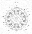
- FIG. 4 is a sectional view taken along an A-A line of FIG. 3 .
- FIG. 5 is a perspective view showing detail inside a housing (without a gear cover) .
- FIG. 6 is a perspective view showing a decelerating mechanism, a rotating shaft, and a rotor.
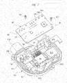
- FIG. 7 is an exploded perspective view showing the interior of the gear cover.
- FIG. 8 is a graph in which acoustic sensitivity (dB) of a vehicle interior (vicinity of a driver's seat) of each of a light vehicle, a midsize vehicle and a luxury vehicle is compared with each other.
- dB acous
- a windshield (front windshield) 11 is provided at a front side of a vehicle 10, such as an automobile.
- a DR-side wiper device 20 and an AS-side wiper device 30 are mounted on the driver's seat side and a passenger's seat side along a vehicle width direction of the vehicle 10 (a right-to-left direction in FIG. 1 ) and at a front end portion of the windshield 11 (a lower side in FIG. 1 ), respectively.
- an opposite wiping type wiper apparatus that includes a wiper device on the driver's seat side and a wiper device on the passenger's seat side is adopted.
- the word "DR-side” denotes a "driver's seat side”
- the word "AS-side” denotes a "passenger's (assistant driver's) seat side”.
- the DR-side wiper device 20 and the AS-side wiper device 30 have a DR-side wiper motor 21 and an AS-side wiper motor 31, respectively.
- the DR-side wiper motor 21 and the AS-side wiper motor 31 respectively drive a DR-side wiper arm 22 and an AS-side wiper arm 32 (not shown in detail in the drawing), which are disposed on the windshield 11, so as to swing at predetermined swing angles.
- wiper blades respectively provided to front ends of the wiper arms 22, 32 carry out a reciprocating wiping-out operation on the windshield 11, whereby rainwater or the like (attached object) is wiped away from the windshield 11 to secure a fine field of view.
- the wiper arms 22, 32 and wiper blades constitute a wiper member of the present invention.
- a cowl top panel 12, which forms a vehicle body of the vehicle 10, is provided at a front end side of the vehicle 10 and in the vicinity of the front end portion of the windshield 11.
- the cowl top panel 12 extends between the DR side and the AS side of the vehicle 10, that is, extends so as to traverse the vehicle 10 in the right-to-left direction, and constitutes a vehicle body fixed portion of the present invention.
- front side members 13 are provided on the DR side and the AS side of the vehicle 10, respectively. Each of the front side members 13 extends in the front-to-rear direction of the vehicle 10 (an up-and-down direction in FIG. 1 ), and constitutes the vehicle body.
- a dash panel upper 14 is provided on a front side of the cowl top panel 12. The dash panel upper 14 also extends so as to traverse the vehicle 10 in the right-to-left direction, and constitutes the vehicle body fixed portion of the present invention.
- both sides in a longitudinal direction of the cowl top panel 12 and both sides in a longitudinal direction of the dash panel upper 14 are firmly fixed to the front side members 13 of the DR side and AS side by welding or the like, respectively.
- Each of the cowl top panel 12, the front side member 13, and the dash panel upper 14 is made of a high-tensile steel plate (high strength material) in the form of a predetermined shape.
- the DR-side wiper device 20 is fixed to a DR-side insertion fixing portion 14a, a DR-side first screw fixing portion 13a and a DR-side second screw fixing portion 13b.
- the DR-side insertion fixing portion 14a is fixed to the dash panel upper 14 by welding or the like.
- the DR-side first screw fixing portion 13a and the DR-side second screw fixing portion 13b are fixed to the front side member 13 of the DR side by welding or the like.
- the AS-side wiper device 30 is fixed to an AS-side first screw fixing portion 14b, an AS-side second screw fixing portion 13c, and an AS-side insertion fixing portion 12a.
- the AS-side first screw fixing portion 14b is fixed to the dash panel upper 14 by welding or the like.
- the AS-side second screw fixing portion 13c is fixed to the front side member 13 of the AS side by welding or the like.
- the AS-side insertion fixing portion 12a is fixed to both the front side member 13 of the AS side and the cowl top panel 12 by welding or the like.
- the AS-side insertion fixing portion 12a has the similar shape to that of a first bracket 3 shown in FIG. 10 .
- each of the DR-side wiper device 20 and AS-side wiper device 30 is fixed to the vehicle body of the vehicle 10 by being supported at three points.
- the same one is used as each of the DR-side wiper motor 21 and the AS-side wiper motor 31.
- Each of the wiper motors 21, 31 has three mounting portions "a”, “b”, and “c”. The mounting portion “a” of the mounting portions “a”, “b”, and “c” is fixed to the vehicle body by being inserted therein.
- each of the mounting portions "b” and “c” of the mounting portions "a", "b", and “c” is fixed to the vehicle body via a fixing bolt (not shown in the drawing).
- the DR-side wiper motor (brushless wiper motor) 21 includes a housing 40 made of aluminum, a motor cover 60 made of plastic, and a gear cover 80 made of plastic.
- the housing 40, the motor cover 60, and the gear cover 80 are coupled to each other with a plurality of fastening screws S (two of them are shown in FIG. 2 ).
- sealing members are provided between the housing 40 and the motor cover 60 and between the housing 40 and the gear cover 80, respectively. They prevent rainwater or the like from entering into the inside of the DR-side wiper motor 21.
- the housing 40 is formed into a predetermined shape by casting a molten aluminum material or the like.
- the housing 40 includes a motor housing unit 41 and a decelerating mechanism housing unit 42.
- the motor housing unit 41 is formed into a bottomed cylindrical shape, as shown in FIG. 3 .
- One end of the motor housing unit 41 in an axial direction (at a right side in FIG. 3 ) is formed as an opening portion.
- a stepped and annular cover fitting portion 41a, on which a fitting portion 62a of the motor cover 60 is mounted, is provided at the opening portion.
- an annular bottom 41b is provided at the other end of the motor housing unit 41 in the axial direction (at a left side in FIG. 3 ).
- a through hole 41c through which a rotating shaft 46 goes rotatably, is formed at a central portion of the annular bottom 41b.
- An annular stepped portion 43 is formed on the interior of the motor housing unit 41.
- the stepped portion 43 is composed of an annular bottom wall 43a and a cylindrical side wall 43b.
- a stator 44 is housed inside the stepped portion 43.
- the stator 44 is formed into a substantially cylindrical shape by stacking a plurality of steel plates 44a made of a magnetic material and bonding them together. A roughly half of an outer periphery of the stator 44 that is positioned closer to the decelerating mechanism housing unit 42 along the axial direction is pressed into the side wall 43b that forms an inner periphery of the motor housing unit 41, whereby both the stator 44 and the motor housing unit 41 are fixed firmly together.
- An uneven engaging portion (not shown in the drawing) is formed between the outer periphery of the stator 44 and the inner periphery of the side wall 43b. This prevents the stator 44 from rotating relative to the housing 40 when the DR-side wiper motor 21 is driven.
- Coil bobbins 44b made of resin, which is an insulator, are provided on both sides of the stator 44 in an axial direction so as to project from the stator 44.
- Coils 44c of a U phase, a V phase, and a W phase (three phases) are wound in the coil bobbins 44b by the predetermined winding number of times.
- An end portion of each of these coils 44c of the U phase, V phase, and W (not shown in the drawing) is electrically connected to the others to form a star connection (Y connection) pattern.
- the connection pattern of the coils 44c is not limited to the star connection pattern as a method of connecting the respective coils 44c.
- Other connecting method such as delta connection (triangular connection) pattern and the like may be adopted, for example.
- each of the plurality of steel plates 44a forming the stator 44 has an annular body portion 44d.
- An outer diameter dimension of the body portion 44d is set to be slightly larger than an inner diameter dimension of the motor housing unit 41. As a result, the stator 44 is pressed into the inside of the motor housing unit 41.
- Six teeth 44e around which the coils 44c are wound are integrally provided in the inside of the body portion 44d in a radial direction. These teeth 44e are arranged at equal intervals (60o intervals) in a circumferential direction of the body portion 44d. Further, six slots SL1 to SL6, in each of which the coils 44c are arranged via the coil bobbin 44b serving as the insulator, are arranged such that each slot is located between a pair of teeth 44e adjacent to each other.
- Each of the coils 44c is electrically connected to a control board 90 (see FIG. 7 ) fixed inside the gear cover 80 via a wiring unit (not shown in the drawing), which is provided in the housing 40.
- a driving current is supplied to each of the coils 44c at predetermined timing from a FET module 96 (see FIG. 7 ) mounted on the control board 90. This causes an electromagnetic force to be generated at the stator 44, whereby a rotor 45 provided inside the stator 44 is driven by a predetermined driving torque (driving force) so as to rotate in a predetermined direction.
- the rotor 45 is rotatably provided inside the stator 44 in the radial direction via a predetermined gap (air gap).
- the rotor 45 is formed into a substantially columnar shape by stacking a plurality of steel plates made of a magnetic material (not shown in the drawing) and bonding them together.
- a permanent magnet 45a formed in a substantially cylindrical shape is mounted on an outer surface of the rotor 45 in its radial direction.
- the permanent magnet 45a is magnetized as four magnetic poles such that the four magnetic poles are arranged alternately (N pole ⁇ S pole ⁇ N pole ⁇ S pole) along a direction of rotation of the rotor 45.
- a brushless motor with a surface permanent magnet (SPM) structure in which the permanent magnet 45a is attached to the surface of the rotor 45 is adopted.
- the DR-side wiper motor 21 is not limited to the brushless motor with the SPM structure.
- a brushless motor with an IPM structure, in which a plurality of permanent magnets is embedded in the rotor 45, may also be adopted as the DR-side wiper motor 21.
- the DR-side wiper motor 21 uses a 4-pole/6-slot type brushless motor as a driving source.
- a shape of the stator 44 becomes mirror symmetric with respect to the rotor 45. Therefore, as indicated by arrows with heavy lines in FIG. 4 , magnetic attractive forces F of the stator 44, which are generated when the rotor 45 is rotated, act so as to cancel each other along the direction of rotation of the rotor 45. This suppresses excitation of the rotor 45, and suppresses the rotational deflection of the rotor 45 and rotating shaft 46. As a result, generation of mechanical noises can be suppressed effectively.
- a frequency of the magnetic noises generated when the rotor 45 is rotated falls within a low frequency range of about 160 Hz to 400 Hz when the DR-side wiper motor 21 operates in a normal mode (at the time of a Lo-level operation).
- a frequency of the magnetic noises generated when the rotor 45 is rotated falls within a low frequency range of about 160 Hz to 400 Hz when the DR-side wiper motor 21 operates in a normal mode (at the time of a Lo-level operation).
- a sense of hearing of a human more readily catches and perceives noise with a high frequency than noise with a low frequency.
- a 2-pole/3-slot type brushless motor becomes an ideal type as the DR-side wiper motor 21.
- the DR-side wiper motor 21 is also required to suppress mechanical noises from being generated as described above.
- the 4-pole/6-slot type brushless motor is adopted as the minimum combination of poles and slots that can satisfy both suppression of generation of mechanical noise and suppression of generation of magnetic noise.
- one end side of the rotating shaft 46 in an axial direction is fixed at a shaft center of the rotor 45.
- a worm 46b provided with spiral teeth 46a formed by rolling or the like is integrally provided at the other end side of the rotating shaft 46 in the axial direction (at a left side in FIG. 6 ).
- the worm 46b formed on the rotating shaft 46 is disposed closer to the decelerating mechanism housing unit 42 than the through hole 41c.
- the worm 46b and a worm wheel 50 engaging with the worm 46b constitute a decelerating mechanism SD.
- a first ball bearing 47 is disposed between the rotor 45 and the worm 46b along the axial direction of the rotating shaft 46.
- the first ball bearing 47 is composed of an outer ring 47a and an inner ring 47b, which are made of steel, and a plurality of steel balls 47c, which are provided between the outer ring 47a and the inner ring 47b.
- the inner ring 47b is fixed to the rotating shaft 46 by fixing means (not shown in the drawing), such as a retaining ring and caulking.
- the outer ring 47a is fitted in a first bearing fitting portion 48 provided between the motor housing unit 41 and the decelerating mechanism housing unit 42 of the housing 40.
- the first ball bearing 47 is fixed to the first bearing fitting portion 48 by pressing it to the first bearing fitting portion 48 by means of a stopper member 48a having elasticity.
- the rotating shaft 46 cannot move in the axial direction. Therefore, the rotating shaft 46 is allowed to smoothly rotate inside the housing 40 without rattling in the axial direction.
- a second ball bearing 49 is fitted to the other end side of the rotating shaft 46 in the axial direction. Similar to the first ball bearing 47, the second ball bearing 49 is composed of an outer ring 49a and an inner ring 49b, which are made of steel, and a plurality of steel balls (not shown in the drawing), which are provided between the outer ring 49a and the inner ring 49b. As the second ball bearing 49, a ball bearing smaller than the first ball bearing 47 is adopted.
- the first ball bearing 47 has a function to rotatably support the rotating shaft 46 and support the rotating shaft 46 so that the rotating shaft 46 cannot move in the axial direction. For this reason, the first ball bearing 47 is provided so as to become large and sturdy.
- the second ball bearing 49 has only a function to suppress the rotational deflection of the other end side of the rotating shaft 46 in the axial direction. For this reason, the second ball bearing 49 with a small size can exert this function adequately.
- miniaturization of the DR-side wiper motor 21 is realized by adopting a brushless motor as the DR-side wiper motor 21 and increasing a reduction gear ratio of the decelerating mechanism SD. Therefore, a pitch of the teeth 46a of the worm 46b becomes narrow, and the worm 46b rotates at a high speed.
- the second ball bearing 49 is provided in order to suppress the rotational deflection of the rotating shaft 46 at the worm 46b side to improve quietness as well as rotation efficiency.
- the second ball bearing 49 may be omitted from the DR-side wiper motor 21.
- an annular first sensor magnet MG1 is fixed between the worm 46b and the first ball bearing 47 along the axial direction of the rotating shaft 46.
- both the worm 46b and the first sensor magnet MG1 are disposed between the first ball bearing 47 and the second ball bearing 49.
- an axial dimension L1 of the rotor 45 (permanent magnet 45a) is made smaller than an axial dimension L2 of the worm 46b (L1 ⁇ L2). This reduces a size of the DR-side wiper motor 21 along the axial direction of the rotating shaft 46 thereof. Further, since the DR-side wiper motor 21 is a brushless motor, it has no commutator or brush. This feature also contributes to a reduction in the size of the DR-side wiper motor 21 along the axial direction of the rotating shaft 46 thereof.
- the first sensor magnet MG1 is magnetized so as to have a plurality of magnetic poles (S poles and N poles) arranged along the direction of rotation of the rotating shaft 46.
- a first Hall IC 94a, a second Hall IC 94b, and a third Hall IC 94c are arranged on an opposing portion to the first sensor magnet MG1 on the control board 90 (see FIG. 7 ). These Hall ICs 94a, 94b, and 94c detect a rotation status of the rotating shaft 46 (the number of rotations, the direction of rotation, and the like).
- the decelerating mechanism housing unit 42 is formed substantially into a bottomed, bathtub shape.
- a bottom 42a and a side wall 42b formed so as to enclose the bottom 42a are provided in the decelerating mechanism housing unit 42.
- an opening 42c is provided on a side of the side wall 42b that is opposite to the bottom 42a (an upper side in FIG. 5 ).
- the bottom 42a and the opening 42c are opposite to each other in an axial direction of the worm wheel 50.
- the opening 42c is sealed by the gear cover 80 (see FIG. 7 ).
- a boss 42d is integrally provided on the bottom 42a of the decelerating mechanism housing unit 42 so that the boss 42d projects toward the outside of the decelerating mechanism housing unit 42 (at an upper side in FIG. 2 ).
- Three mounting legs (fixing legs) 42e are integrally provided on the side wall 42b of the decelerating mechanism housing unit 42 so that the mounting legs 42e project radially from the boss 42d as a central portion.
- Rubber bushes RB through each of which a fixing bolt (not shown in the drawing) is configured to put, are attached to two of these mounting legs 42e, respectively.
- an insertion rubber IR which is configured to be inserted in the DR-side insertion fixing portion 14a (see FIG. 1 ), is attached to the remaining one of the mounting legs 42e.
- the DR-side wiper motor 21 is fixed to the vehicle 10 via the rubber bushes RB and the insertion rubber IR, and each of the rubber bushes RB and the insertion rubber IR function as buffering members. Therefore, when the DR-side wiper motor 21 is fixed to the vehicle 10 (see FIG. 1 ), vibration of the DR-side wiper motor 21 is hardly transmitted to the vehicle 10, and this further improves the quietness of the vehicle 10. Conversely, since vibration of the vehicle 10 is hardly transmitted to the DR-side wiper motor 21, it is possible to protect the DR-side wiper motor 21 from the vibration.
- the worm wheel 50 is rotatably housed inside the decelerating mechanism housing unit 42.
- the worm wheel 50 is made of, for example, polyacetal (POM) resin and is formed into a substantially disc shape.
- Gear teeth (teeth) 50a are formed on the outer periphery of the worm wheel 50.
- the teeth 46a of the worm 46b engage with the gear teeth 50a of the worm wheel 50.
- One end side of an output shaft 51 in an axial direction is fixed to a center of rotation of the worm wheel 50.
- the output shaft 51 is rotatably supported by the boss 42d of the decelerating mechanism housing unit 42.
- the other end side of the output shaft 51 in the axial direction extends to the outside of the decelerating mechanism housing unit 42, and a base end of the DR-side wiper arm 22 (see FIG. 1 ) is fixed to the other end of the output shaft 51 in the axial direction. This causes the output shaft 51 to be rotated by means of the rotor 45 (see FIG. 3 ).
- speed of rotation of the rotating shaft 46 is reduced by the decelerating mechanism SD to create a high torque, whereby turning force with the high torque thus reduced is transmitted from the output shaft 51 to the DR-side wiper arm 22 provided outside the decelerating mechanism housing unit 42.
- the decelerating mechanism SD reduces the speed of rotation of the rotor 45, and transmits the turning force with the high torque, which is created by reducing the speed of rotation, to the DR-side wiper arm 22.
- a disc-shaped second sensor magnet MG2 is fixed at the center of rotation of the worm wheel 50 and at a side opposite to the side on which the output shaft 51 is provided.
- the second sensor magnet MG2 is magnetized so as to have a plurality of magnetic poles (S poles and N poles) arranged along the direction of rotation of the output shaft 51.
- the second sensor magnet MG2 is provided at one end side of the output shaft 51 in the axial direction, and is rotated together with the output shaft 51 and worm wheel 50.
- An MR sensor 95 is disposed on an opposing portion to the second sensor magnet MG2 on the control board 90 (see FIG. 7 ). The MR sensor 95 thus detects rotation statuses (the direction of rotation, a rotational position, and the like) of the output shaft 51 and the worm wheel 50.
- a second bearing fitting portion 52 is provided on the side wall 42b of the decelerating mechanism housing unit 42.
- the second bearing fitting portion 52 is disposed coaxially with the first bearing fitting portion 48 (see FIG. 3 ), and a second ball bearing 49 is housed in the second bearing fitting portion 52.
- the second ball bearing 49 is fitted in the second bearing fitting portion 52 by putting the second ball bearing 49 through the through hole 41c and the first bearing fitting portion 48 in a state where the second ball bearing 49 is mounted on the other end side of the rotating shaft 46 in the axial direction.
- the second ball bearing 49 is not pressed into the second bearing fitting portion 52, but is fitted loosely therein with a small clearance. As a result, for example, even if imperfect alignment between the first bearing fitting portion 48 and the second bearing fitting portion 52 occurs slightly at the time of manufacturing the housing 40, rotational resistance of the rotating shaft 46 does not increase. This also suppresses mechanical noises generated by the DR-side wiper motor 21, whereby it is possible to improve its quietness.
- the motor cover 60 is formed into a bottomed, cylindrical shape.
- the motor cover 60 includes a bottom 61 formed into a substantially disc shape and a cylindrical wall 62 that encircles the bottom 61.
- a concave portion 61a hollowed toward the cylindrical wall 62 is provided at a central portion of the bottom 61.
- the concave portion 61a is provided in order to enhance the strength of the bottom 61. In other words, by providing the concave portion 61a on the bottom 61, the bottom 61 is hardly bended. This prevents the motor cover 60 from resonating with the vibration or the like when the DR-side wiper motor 21 is operated, whereby the quietness of the DR-side wiper motor 21 is improved.
- the fitting portion 62a which is fitted on the cover fitting portion 41a of the motor housing unit 41, is provided at a portion of the cylindrical wall 62 that is closer to the motor housing unit 41.
- This fitting portion 62a is formed into an annular shape, and is also formed into a stepped shape in the same manner as the cover fitting portion 41a so that the fitting portion 62a fits with the cover fitting portion 41a.
- the gear cover 80 seals the opening 42c (see FIG. 5 ) of the decelerating mechanism housing unit 42, and has an outline shape slimier to that of the opening 42c.
- the gear cover 80 includes a bottom wall 81 and a side wall 82.
- the control board (board) 90 is fixed to the bottom wall 81 inside the gear cover 80 by means of first fixing screws SC1.
- a connector connecting portion 82a to which an outer connector (not shown in the drawing) on the vehicle 10 side is connected, is integrally provided on the side wall 82 of the gear cover 80. Terminals (not shown in the drawing) at one end sides of a plurality of conductive members CM are exposed inside the connector connecting portion 82a. On the other hand, terminals TM at the other end sides of the conductive members CM are electrically connected to the control board 90. An on-vehicle battery and a wiper switch (not shown in the drawing) are electrically connected to the outer connector on the vehicle 10 side.
- the control board 90 includes a first surface 91 and a second surface 92.
- the first surface 91 faces a side of the gear cover 80 opposite to the bottom wall 81, that is, the side on which the rotating shaft 46 and output shaft 51 are arranged (an upper side in FIG. 7 ).
- the second surface 92 faces the bottom wall 81 side of the gear cover 80, that is, the side opposite to the first surface 91 (a lower side in FIG. 7 ).
- a CPU 93, the first Hall IC 94a, the second Hall IC 94b, and the third Hall IC 94c, and the MR sensor 95 are provided on the first surface 91 of the control board 90.
- the CPU 93 is configured to totally control the DR-side wiper motor 21.
- the first, second, and third Hall ICs 94a, 94b, and 94c face the first sensor magnet MG1 (see FIG. 6 ).
- the MR sensor 95 faces the second sensor magnet MG2 (see FIG. 5 ).
- the three Hall ICs 94a, 94b, and 94c are arranged at predetermined intervals along the direction of rotation of the first sensor magnet MG1.
- an FET module 96 and a capacitor CP are provided on the second surface 92 of the control board 90.
- the FET module 96 is an electronic component for a driving system.
- the capacitor CP is another electronic component.
- the FET module 96 is composed of a plurality of switching elements that switch energized states of the respective coils 44c of three phases (see FIG. 4 ) at a high speed. Therefore, the FET module 96 tends to generate heat. Accordingly, in order to improve a heat dissipation property of the FET module 96, the FET module 96 is connected to the housing 40 via a heat conductive member 97a and a heat conductive sheet 97b.
- the FET module 96 is fixed to the bottom wall 81 of the gear cover 80 by means of a pair of second fixing screws SC2 before the control board 90 is mounted on the bottom wall 81 of the gear cover 80. Then, the FET module 96 is actually mounted on the second surface 92 of the control board 90 by connecting means such as soldering.
- the CPU 93 and the FET module 96 are configured to supply a drive current to the DR-side wiper motor 21 to control the rotation of the rotor 45 (see FIG. 4 ).
- the CPU 93 controls the FET module 96 on the basis of values (rectangular wave signals) detected by each of the Hall ICs 94a, 94b, and 94c and the MR sensor 95. Thus, the rotation of the rotor 45 is controlled.
- the luxury vehicle a weight of the vehicle is a 2-ton class and the like
- the luxury vehicle since the case of the luxury vehicle (a weight of the vehicle is a 2-ton class and the like) is designed with emphasis on the quietness of its vehicle interior, the luxury vehicle often adopts lots of steel plates with high rigidity and adds a noise-proofing sheet. For this reason, in the case of the luxury vehicle, noises with high frequencies of about 1 kHz hardly echo in the vehicle interior thereof.
- the midsize vehicle (a weight of the vehicle is less than 1.5 ton and the like) has acoustic sensitivity (dB) of the vehicle interior between that of the light vehicle and that of the luxury vehicle.
- each of the light vehicle, the midsize vehicle, and the luxury vehicle has the acoustic sensitivities (dB) that is not that different to each other.
- the noises with a low frequency range of about 150 Hz to 300 Hz are noises that hardly echo in the vehicle interior and are hardly heard regardless of the rigidity of the vehicle body or the like.
- the DR-side wiper motor 21 is the 4-pole/6-slot type brushless motor in which the stator 44 is fixed to the housing 40, which is fixed to the vehicle 10. Therefore, this structure allows the magnetic noises, which has low frequencies of about 150 Hz to 500 Hz, from the DR-side wiper motor 21 to be easily matched with a low frequency range of about 160 Hz to 400 Hz.
- the DR-side wiper motor 21 by matching both the frequencies of magnetic noises and the frequencies of mechanical noises generated by the DR-side wiper motor 21 to be integrated into a low frequency range of about 150 Hz to 500 Hz, more preferably, to a narrower low frequency range of about 160 Hz to 400 Hz, it is possible to reduce a difference in the acoustic sensitivity (dB) between the light vehicle and the luxury vehicle (which is indicated by the area of a hatched portion (a) in FIG. 8 , that is, a difference between the maximum acoustic sensitivity and the minimum acoustic sensitivity) .
- This allows the DR-side wiper motor 21 to be applied to the light vehicle as well as to the luxury vehicle without any problem.
- the DR-side wiper motor 21 of the present invention its versatility can be improved widely by integrating the frequency range of noises generated by the DR-side wiper motor 21 into a low frequency range.
- a target for noise suppression is generally determined to some extent according to a material making up the buffering member such as buffering members dedicated to suppress noises with high frequencies, buffering members dedicated to suppress noises with low frequencies, and the like. For that reason, in a case where frequency variation of targeted motors (the width of the overall frequency range of the motor) is wide, it becomes difficult to carry out measure against the whole noises for the motor.
- a motor with a brush described as a reference example has many magnetic poles (for example, four magnetic poles) in association with reduction in its size and weight.
- Such a motor is provided with three brushes in order to be capable of changing its wiping speed between a "Hi level” and a "Lo level”.
- This motor with the brushes generates magnetic noises with high frequencies, especially frequencies around 1 kHz. For that reason, a difference in the acoustic sensitivity (dB) between the light vehicle and the luxury vehicle (which is indicated by the area of a hatched portion (b) in FIG. 8 , that is, a difference between the maximum acoustic sensitivity and the minimum acoustic sensitivity) becomes large, and it becomes difficult to apply the motor to the light vehicle.
- dB acoustic sensitivity
- the conventional technique described in Background of the Invention adopted a brushless motor (6-pole/9-slot type motor) having more magnetic poles and slots than those of the motor according to the present invention.
- a stator is fixed to a yoke that is a separate element to a gear housing. Therefore, magnetic noises from the motor according to the conventional technique are higher in frequency than the magnetic noises from the motor according to the present invention, and have a frequency around 600 Hz. For that reason, in the case of the motor of the conventional technique, a difference in the acoustic sensitivity (dB) between the light vehicle and the luxury vehicle (which is indicated by the area of a hatched portion (c) in FIG.
- dB acoustic sensitivity
- the shape of the stator 44 can be made mirror symmetric with respect to the rotor 45. Therefore, rotational deflection of the rotor 45 can be suppressed. Further, as the minimum number of poles and the minimum number of slots that can suppress the rotational deflection of the rotor 45, a frequency of magnetic noises generated during the rotation of the rotor can approach a frequency of mechanical noises of the decelerating mechanism SD (low frequency around a frequency range of about 150 Hz to 300 Hz). This makes it possible to integrate each of frequencies of magnetic noises and mechanical noises generated by the DR-side wiper motor 21 into a low frequency range thereof.
- the brushless wiper motor can easily be applied to light vehicles and luxury vehicles, and it can also be applied to electric vehicles, hybrid vehicles and the like (improvement in general versatility) .
- the mounting legs 42e that are respectively fixed to the cowl top panel 12, the front side member 13, and the dash panel upper 14 are provided in the housing 40 while fixing the stator 44 inside the housing 40.
- the stator 40 which is a source of the magnetic noises, can be fixed to the vehicle 10 only via the housing 40. Therefore, the acoustic sensitivity (dB) of the vehicle interior can be estimated easily by merely calculating rigidity of the housing 40, for example.
- dB acoustic sensitivity
- the decelerating mechanism SD has the worm 46b rotated by the rotor 45, and the worm wheel 50 provided with the gear teeth 50a that is configured to engage with the worm 46b wherein the output shaft 51 is provided on the center of rotation of the worm wheel.
- the axial dimension L1 of the rotor 45 is made smaller than the axial dimension L2 of the worm 46b (L1 ⁇ L2). This makes it possible to make the size of the DR-side wiper motor 21 along the axial direction of the rotating shaft 46 smaller, and it is possible to reduce weight thereof further. Thus, it is possible to apply the DR-side wiper motor 21 to light vehicles easily.
- the mounting legs 42e are fixed to the cowl top panel 12, the front side member 13, and the dash panel upper 14 via the rubber bush RB, the rubber bush RB, and the insertion rubber IR, respectively. Therefore, the vibration of the DR-side wiper motor 21 is hardly transmitted to the vehicle 10. This makes it possible to make the acoustic sensitivity (dB) of the vehicle interior smaller. Further, the DR-side wiper motor 21 is protected from the vibration of the vehicle 10. This makes it possible to prevent the DR-side wiper motor 21 from being damaged quickly.
- the frequencies of noises generated by the DR-side wiper motor 21 can be integrated into a low frequency range. This makes it possible to improve the versatility of the DR-side wiper motor 21 significantly. Furthermore, reduction in variation of the frequencies (the width of the overall frequency range of the motor) allows the frequency range for implementing measure against noise to be limited. For this reason, further measure against noise using buffering members (insertion rubbers IR, rubber bushes RB, and the like) becomes easy.
- the frequencies of noises generated by the DR-side wiper motor 21 can be integrated into a low frequency range. For this reason, an influence of operating noise by the vehicle can be reduced.
- the DR-side wiper motor 21 is hardly influenced by vibration or the like from the vehicle by narrowing the width of the overall frequency range of the motor. For this reason, it is possible to suppress a resonance and/or vibration amplification from being generated, and as a result, the operating noise of the DR-side wiper motor 21 can be reduced.
- the frequency (Hz) is calculated by a formula: ⁇ (the number of slots or the number of teeth) ⁇ (the number of rotations of the output shaft (rpm) ) ⁇ (the reduction gear ratio) ⁇ / 60.
- This formula puts emphasis on a frequency component caused by the slots or teeth.
- FIG. 9 shows a perspective view of a wiper device according to the second embodiment.
- the so-called twin wiper apparatus has been described in which the DR-side wiper device 20 and the AS-side wiper device 30 are mounted on the driver's seat side and the passenger's seat side along the vehicle width direction of the vehicle 10, respectively, and the DR-side wiper arm 22 and the AS-side wiper arm 32 are driven to swing at their respective swing angles, respectively.
- FIG. 9 a case where a brushless wiper motor 100 is applied to a modular wiper device 101 is shown in the second embodiment.
- the modular wiper device 101 includes a pipe frame 102.
- a portion of the brushless wiper motor 100 that substantially serves as the center of gravity is fixed to an approximate central part of the pipe frame 102 in its longitudinal direction (not shown in the drawing in detail). Therefore, the modular wiper device 101 is well balanced in weight, thereby easily carrying it as a single wiper device.
- the brushless wiper motor 100 applied to the modular wiper device 101 includes one mounting leg 42e that is fixed by a fixing bolt (not shown in the drawing) .
- This mounting leg 42e is fixed to a dash panel upper 14 (see FIG. 1 ), which serves as a vehicle body fixed portion, via a rubber bush RB.
- the rubber bush RB provided on the mounting leg 42e may be replaced by an insertion rubber IR to fix the mounting leg 42e to a vehicle.
- Structural elements of the brushless wiper motor 100 other than the structural elements described above are the same as the structural elements of the DR-side wiper motor 21 according to the first embodiment.
- a first pivot holder 103a and a second pivot holder 103b are fixed to both sides of the pipe frame 102 in the longitudinal direction, respectively.
- the first and second pivot holders 103a, 103b rotatably support a first pivot 104a and a second pivot 104b, respectively.
- a first mounting portion 105a and a second mounting portion 105b which are respectively fixed to front side members 13 (see FIG. 1 ), are provided on the first pivot holder 103a and the second pivot holder 103b.
- a link mechanism 106 is provided between base ends of the first and second pivots 104a, 104b.
- the link mechanism 106 is configured to transmit a swinging motion of an output shaft 51 to the first and second pivots 104a, 104b.
- Base ends of wiper arms 22, 32 are fixed to front ends of the first and second pivots 104a, 104b, respectively.
- the link mechanism 106 is disposed between the output shaft 51 and the wiper arms 22, 32.
- the link mechanism 106 is composed of a crank arm 106a, a pair of drive levers 106b, 106c, a connection rod 106d, and a drive rod 106e.
- the crank arm 106a is fixed to the output shaft 51.
- the pair of drive levers 106b, 106c is fixed to the base ends of the first and second pivots 104a, 104b, respectively.
- the connection rod 106d is provided between the drive lever 106b and the drive lever 106c.
- the drive rod 106e provided between the drive lever 106c and the crank arm 106a.
- each of the crank arm 106a, the drive levers 106b, 106c, the connection rod 106d, and drive rod 106e, which constitute the link mechanism 106 is formed into a predetermined shape by pressing a steel plate. This process also contributes to weight saving.
- the second embodiment configured as described above can achieve the same effects as those of the first embodiment.
- the present invention is not limited to each of the above embodiments.
- the three mounting legs 42e are provided in the DR-side wiper motor 21, one of the three mounting legs 42e is provided as an insertion type mounting leg, and the other two of them are provided as bolt-fixed type mounting legs.
- the present invention is not limited to this, and all of the three mounting legs 42e may be provided as the bolt-fixed type mounting legs.
- the DR-side wiper motor 21 and the brushless wiper motor 100 drives the DR-side wiper arm 22 and AS-side wiper arm 32 so as to swing on the windshield 11, respectively.
- the present invention is not limited to this, and can also be adopted as a wiper motor that drives a wiper arm so as to swing on the rear window.
- the present invention is applied to an inner rotor type brushless wiper motor in which the rotor 45 is rotatably disposed inside the stator 44.
- the present invention is not limited to such a wiper motor, but can also be applied to an outer rotor type brushless wiper motor in which a rotor is disposed outside a stator.
- a brushless wiper motor is used as a driving source for a wiper device that is mounted on a vehicle such as an automobile, and is used to drive a wiper arm to swing and wipe rainwater and the like attached onto a windshield away from the windshield.
Landscapes
- Engineering & Computer Science (AREA)
- Power Engineering (AREA)
- Mechanical Engineering (AREA)
- Microelectronics & Electronic Packaging (AREA)
- Automation & Control Theory (AREA)
- Motor Or Generator Frames (AREA)
- Connection Of Motors, Electrical Generators, Mechanical Devices, And The Like (AREA)
- Permanent Magnet Type Synchronous Machine (AREA)
Claims (5)
- Bürstenloser Wischermotor (21, 31), der so konfiguriert ist, dass er ein Wischerelement zum Schwingen veranlasst, wobei das Wischerelement einen an einer Windschutzscheibe (11) eines Fahrzeugs (10) angebrachten Gegenstand von der Windschutzscheibe (11) weg wischt, wobei der bürstenlose Wischermotor (21, 31) umfasst:einen Stator (44), der innerhalb eines Gehäuses befestigt ist, wobei sechs Zähne (44e) integral in einem Inneren des Stators (44) in einer radialen Richtung vorgesehen sind;eine Spule (44c), die um jeden der Zähne (44e) gewickelt ist;einen Rotor (45), der so konfiguriert ist, dass er in Bezug auf den Stator (44) rotiert;einen Permanentmagneten (45a), der auf dem Rotor (45) vorgesehen ist, wobei der Permanentmagnet (45a) vier Magnetpole aufweist, die abwechselnd entlang einer Rotationsrichtung des Rotors (45) angeordnet sind;einen Verzögerungsmechanismus (SD), der in dem Gehäuse (40) untergebracht ist, wobei der Verzögerungsmechanismus (SD) so konfiguriert ist, dass er die Rotationsgeschwindigkeit des Rotors (45) reduziert;eine Abtriebswelle (51), die so konfiguriert ist, dass sie die Rotation des Verzögerungsmechanismus (SD) auf das Wischerelement überträgt,dadurch gekennzeichnet, dassdas Gehäuse (40) durch Gießen eines geschmolzenen Aluminiummaterials oder dergleichen in eine vorbestimmte Form ausgebildet wird, und das Gehäuse (40) eine Motorgehäuseeinheit (41), in der der Stator (44) untergebracht ist, und eine Verzögerungsmechanismus-Gehäuseeinheit (42) umfasst, in der der Verzögerungsmechanismus (SD) untergebracht ist,wobei die Motorgehäuseeinheit (41) zu einer zylindrischen Form mit Boden ausgebildet ist, wobei der bürstenlose Wischermotor (21, 31) eine Vielzahl von Befestigungsschenkeln (42e) aufweist, die an dem Gehäuse (40) vorgesehen sind undwenigstens einer der Vielzahl von Befestigungsschenkeln (42e) an einem festen Abschnitt (14) der Fahrzeugkarosserie befestigbar ist, der sich in einer Rechts-nach-Links-Richtung des Fahrzeugs erstreckt (10).
- Bürstenloser Wischermotor (21, 31) nach Anspruch 1,
wobei Frequenzen von Geräuschen, die durch den bürstenlosen Wischermotor (21, 31) erzeugt werden, gleich oder niedriger als 500 Hz auftreten. - Bürstenloser Wischermotor (21, 31) nach Anspruch 1,
wobei der Verzögerungsmechanismus (SD) umfasst:eine Schnecke (46b), die durch den Rotor (45) rotiert wird; undein Schneckenrad (50), das mit Zähnen (50a) versehen ist, wobei die Zähne (50a) so konfiguriert sind, dass sie in die Schnecke (46b) eingreifen, wobei die Abtriebswelle (51) an einem Rotationszentrum des Schneckenrads (50) vorgesehen ist, undwobei eine axiale Abmessung des Rotors (45) kleiner als eine axiale Abmessung der Schnecke (46b) ist. - Bürstenloser Wischermotor (21, 31) nach Anspruch 1,
wobei mindestens einer der Vielzahl von Befestigungsschenkeln (42e) über ein Pufferelement an einem festen Abschnitt (14) der Fahrzeugkarosserie befestigbar ist. - Bürstenloser Wischermotor (21, 31) nach Anspruch 1,
wobei jeder der Zähne (44e) des Stators (44) in Bezug auf den Rotor (45) dem anderen gegenüberliegt.
Applications Claiming Priority (2)
| Application Number | Priority Date | Filing Date | Title |
|---|---|---|---|
| JP2015083856A JP6495080B2 (ja) | 2015-04-16 | 2015-04-16 | ブラシレスワイパモータ |
| PCT/JP2016/061295 WO2016167168A1 (ja) | 2015-04-16 | 2016-04-06 | ブラシレスワイパモータ |
Publications (3)
| Publication Number | Publication Date |
|---|---|
| EP3285378A1 EP3285378A1 (de) | 2018-02-21 |
| EP3285378A4 EP3285378A4 (de) | 2018-11-14 |
| EP3285378B1 true EP3285378B1 (de) | 2020-10-28 |
Family
ID=57125887
Family Applications (1)
| Application Number | Title | Priority Date | Filing Date |
|---|---|---|---|
| EP16779959.2A Active EP3285378B1 (de) | 2015-04-16 | 2016-04-06 | Bürstenloser wischermotor |
Country Status (5)
| Country | Link |
|---|---|
| US (2) | US10040426B2 (de) |
| EP (1) | EP3285378B1 (de) |
| JP (1) | JP6495080B2 (de) |
| CN (1) | CN107431422B (de) |
| WO (1) | WO2016167168A1 (de) |
Families Citing this family (7)
| Publication number | Priority date | Publication date | Assignee | Title |
|---|---|---|---|---|
| FR3066968B1 (fr) * | 2017-06-02 | 2021-01-01 | Valeo Systemes Dessuyage | Moto-reducteur pour systeme d'essuyage de vehicule automobile |
| US20190068025A1 (en) * | 2017-08-30 | 2019-02-28 | GM Global Technology Operations LLC | Magnetically-Driven Actuator Assembly |
| FR3074887B1 (fr) * | 2017-12-08 | 2020-02-14 | Valeo Systemes D'essuyage | Moto-reducteur pour systeme d'essuyage de vehicule automobile |
| FR3074888B1 (fr) * | 2017-12-08 | 2019-12-06 | Valeo Systemes D'essuyage | Moto-reducteur pour systeme d'essuyage de vehicule automobile |
| JP7490602B2 (ja) | 2021-03-10 | 2024-05-27 | 株式会社東芝 | ブラシレスモータ駆動装置 |
| CN115912843A (zh) * | 2023-01-04 | 2023-04-04 | 南京信息工程大学 | 一种组合型两自由度永磁式步进电机 |
| CN119945211B (zh) * | 2025-04-10 | 2025-07-01 | 上海禹点电子科技有限公司 | 一种基于正余弦位置信号的无刷雨刮电机控制方法、系统及装置 |
Family Cites Families (13)
| Publication number | Priority date | Publication date | Assignee | Title |
|---|---|---|---|---|
| US5355061A (en) * | 1992-01-24 | 1994-10-11 | Grimes Aerospace Company | Windshield wiper system |
| US7676880B2 (en) * | 2002-05-15 | 2010-03-16 | Trico Products Corporation | Direct drive windshield wiper assembly |
| US7389561B2 (en) * | 2002-05-15 | 2008-06-24 | Trico Products Corporation | Tandem windshield wiper system with direct drive motor |
| JP4161833B2 (ja) * | 2003-07-24 | 2008-10-08 | 三菱自動車工業株式会社 | ワイパモータの取り付け構造 |
| CA2536676A1 (en) * | 2003-09-15 | 2005-03-24 | Intier Automotive Closures Inc. | Reversing-motor windshield wiper system |
| DE102008043173A1 (de) * | 2008-07-04 | 2010-01-07 | Robert Bosch Gmbh | Getriebe-Antriebseinheit mit einer Selbsthemmvorrichtung |
| CN201263107Y (zh) * | 2008-08-28 | 2009-06-24 | 成都华川电装有限责任公司 | 雨刮电机总成 |
| CN201518442U (zh) * | 2009-09-23 | 2010-06-30 | 湖北钱潮汽车零部件有限公司 | 一种后雨刮电机总成 |
| JP2013223317A (ja) | 2012-04-16 | 2013-10-28 | Mitsuba Corp | ブラシレスワイパモータ |
| DE102012223835A1 (de) * | 2012-12-19 | 2014-06-26 | Robert Bosch Gmbh | Entkoppelter Wischerantrieb |
| JP6302638B2 (ja) * | 2013-02-26 | 2018-03-28 | 株式会社ミツバ | ワイパ装置 |
| CN105102280B (zh) * | 2013-03-29 | 2018-01-02 | 株式会社美姿把 | 无刷雨刮器电动机 |
| JP2015037331A (ja) * | 2013-08-10 | 2015-02-23 | 株式会社ミツバ | ブラシレスモータ |
-
2015
- 2015-04-16 JP JP2015083856A patent/JP6495080B2/ja active Active
-
2016
- 2016-04-06 EP EP16779959.2A patent/EP3285378B1/de active Active
- 2016-04-06 CN CN201680021699.7A patent/CN107431422B/zh active Active
- 2016-04-06 US US15/565,531 patent/US10040426B2/en active Active
- 2016-04-06 WO PCT/JP2016/061295 patent/WO2016167168A1/ja not_active Ceased
-
2018
- 2018-07-09 US US16/029,989 patent/US10442401B2/en active Active
Non-Patent Citations (1)
| Title |
|---|
| None * |
Also Published As
| Publication number | Publication date |
|---|---|
| WO2016167168A1 (ja) | 2016-10-20 |
| JP2016208573A (ja) | 2016-12-08 |
| US20180086308A1 (en) | 2018-03-29 |
| CN107431422B (zh) | 2020-02-14 |
| CN107431422A (zh) | 2017-12-01 |
| US10442401B2 (en) | 2019-10-15 |
| JP6495080B2 (ja) | 2019-04-03 |
| EP3285378A4 (de) | 2018-11-14 |
| US20180312138A1 (en) | 2018-11-01 |
| US10040426B2 (en) | 2018-08-07 |
| EP3285378A1 (de) | 2018-02-21 |
Similar Documents
| Publication | Publication Date | Title |
|---|---|---|
| EP3285378B1 (de) | Bürstenloser wischermotor | |
| CN106663991B (zh) | 无刷雨刮电机 | |
| JP6634372B2 (ja) | ブラシレスワイパモータ | |
| US10336299B2 (en) | Brushless wiper motor | |
| JP6650302B2 (ja) | ブラシレスモータおよびワイパ装置 | |
| US10116186B2 (en) | Brushless wiper motor | |
| JP6681490B2 (ja) | ブラシレスワイパモータおよびワイパ装置 | |
| JP7080704B2 (ja) | ロータ、モータ及びブラシレスワイパーモータ | |
| JP2012090496A (ja) | モータ及び電動パワーステアリング装置 | |
| JP2013223317A (ja) | ブラシレスワイパモータ | |
| JP6640586B2 (ja) | ブラシレスモータ | |
| JP5446045B2 (ja) | 回転電機及び電動パワーステアリング装置 | |
| JP6552422B2 (ja) | ブラシレスモータ | |
| JP6095662B2 (ja) | ワイパモータ | |
| WO2018012074A1 (ja) | ブラシレスワイパモータ | |
| JP2021048661A (ja) | ブラシレスモータ | |
| JP2017189110A (ja) | モータ装置 | |
| JP2017225239A (ja) | モータハウジング、モータ、減速機付モータ | |
| JP6174416B2 (ja) | モータ装置 | |
| JP2011157037A (ja) | 電動パワーステアリング装置 |
Legal Events
| Date | Code | Title | Description |
|---|---|---|---|
| STAA | Information on the status of an ep patent application or granted ep patent |
Free format text: STATUS: THE INTERNATIONAL PUBLICATION HAS BEEN MADE |
|
| PUAI | Public reference made under article 153(3) epc to a published international application that has entered the european phase |
Free format text: ORIGINAL CODE: 0009012 |
|
| STAA | Information on the status of an ep patent application or granted ep patent |
Free format text: STATUS: REQUEST FOR EXAMINATION WAS MADE |
|
| 17P | Request for examination filed |
Effective date: 20171116 |
|
| AK | Designated contracting states |
Kind code of ref document: A1 Designated state(s): AL AT BE BG CH CY CZ DE DK EE ES FI FR GB GR HR HU IE IS IT LI LT LU LV MC MK MT NL NO PL PT RO RS SE SI SK SM TR |
|
| AX | Request for extension of the european patent |
Extension state: BA ME |
|
| DAV | Request for validation of the european patent (deleted) | ||
| DAX | Request for extension of the european patent (deleted) | ||
| A4 | Supplementary search report drawn up and despatched |
Effective date: 20181015 |
|
| RIC1 | Information provided on ipc code assigned before grant |
Ipc: B60S 1/16 20060101ALI20181009BHEP Ipc: B60S 1/24 20060101ALI20181009BHEP Ipc: H02K 7/14 20060101ALI20181009BHEP Ipc: B60S 1/04 20060101ALI20181009BHEP Ipc: B60S 1/08 20060101ALI20181009BHEP Ipc: H02K 21/14 20060101AFI20181009BHEP |
|
| STAA | Information on the status of an ep patent application or granted ep patent |
Free format text: STATUS: EXAMINATION IS IN PROGRESS |
|
| 17Q | First examination report despatched |
Effective date: 20190925 |
|
| GRAP | Despatch of communication of intention to grant a patent |
Free format text: ORIGINAL CODE: EPIDOSNIGR1 |
|
| STAA | Information on the status of an ep patent application or granted ep patent |
Free format text: STATUS: GRANT OF PATENT IS INTENDED |
|
| INTG | Intention to grant announced |
Effective date: 20200519 |
|
| GRAS | Grant fee paid |
Free format text: ORIGINAL CODE: EPIDOSNIGR3 |
|
| GRAA | (expected) grant |
Free format text: ORIGINAL CODE: 0009210 |
|
| STAA | Information on the status of an ep patent application or granted ep patent |
Free format text: STATUS: THE PATENT HAS BEEN GRANTED |
|
| AK | Designated contracting states |
Kind code of ref document: B1 Designated state(s): AL AT BE BG CH CY CZ DE DK EE ES FI FR GB GR HR HU IE IS IT LI LT LU LV MC MK MT NL NO PL PT RO RS SE SI SK SM TR |
|
| REG | Reference to a national code |
Ref country code: GB Ref legal event code: FG4D |
|
| REG | Reference to a national code |
Ref country code: CH Ref legal event code: EP |
|
| REG | Reference to a national code |
Ref country code: AT Ref legal event code: REF Ref document number: 1329227 Country of ref document: AT Kind code of ref document: T Effective date: 20201115 |
|
| REG | Reference to a national code |
Ref country code: DE Ref legal event code: R096 Ref document number: 602016046770 Country of ref document: DE |
|
| REG | Reference to a national code |
Ref country code: IE Ref legal event code: FG4D |
|
| REG | Reference to a national code |
Ref country code: AT Ref legal event code: MK05 Ref document number: 1329227 Country of ref document: AT Kind code of ref document: T Effective date: 20201028 |
|
| REG | Reference to a national code |
Ref country code: NL Ref legal event code: MP Effective date: 20201028 |
|
| PG25 | Lapsed in a contracting state [announced via postgrant information from national office to epo] |
Ref country code: PT Free format text: LAPSE BECAUSE OF FAILURE TO SUBMIT A TRANSLATION OF THE DESCRIPTION OR TO PAY THE FEE WITHIN THE PRESCRIBED TIME-LIMIT Effective date: 20210301 Ref country code: RS Free format text: LAPSE BECAUSE OF FAILURE TO SUBMIT A TRANSLATION OF THE DESCRIPTION OR TO PAY THE FEE WITHIN THE PRESCRIBED TIME-LIMIT Effective date: 20201028 Ref country code: NL Free format text: LAPSE BECAUSE OF FAILURE TO SUBMIT A TRANSLATION OF THE DESCRIPTION OR TO PAY THE FEE WITHIN THE PRESCRIBED TIME-LIMIT Effective date: 20201028 Ref country code: NO Free format text: LAPSE BECAUSE OF FAILURE TO SUBMIT A TRANSLATION OF THE DESCRIPTION OR TO PAY THE FEE WITHIN THE PRESCRIBED TIME-LIMIT Effective date: 20210128 Ref country code: FI Free format text: LAPSE BECAUSE OF FAILURE TO SUBMIT A TRANSLATION OF THE DESCRIPTION OR TO PAY THE FEE WITHIN THE PRESCRIBED TIME-LIMIT Effective date: 20201028 Ref country code: GR Free format text: LAPSE BECAUSE OF FAILURE TO SUBMIT A TRANSLATION OF THE DESCRIPTION OR TO PAY THE FEE WITHIN THE PRESCRIBED TIME-LIMIT Effective date: 20210129 |
|
| REG | Reference to a national code |
Ref country code: LT Ref legal event code: MG4D |
|
| PG25 | Lapsed in a contracting state [announced via postgrant information from national office to epo] |
Ref country code: SE Free format text: LAPSE BECAUSE OF FAILURE TO SUBMIT A TRANSLATION OF THE DESCRIPTION OR TO PAY THE FEE WITHIN THE PRESCRIBED TIME-LIMIT Effective date: 20201028 Ref country code: AT Free format text: LAPSE BECAUSE OF FAILURE TO SUBMIT A TRANSLATION OF THE DESCRIPTION OR TO PAY THE FEE WITHIN THE PRESCRIBED TIME-LIMIT Effective date: 20201028 Ref country code: ES Free format text: LAPSE BECAUSE OF FAILURE TO SUBMIT A TRANSLATION OF THE DESCRIPTION OR TO PAY THE FEE WITHIN THE PRESCRIBED TIME-LIMIT Effective date: 20201028 Ref country code: BG Free format text: LAPSE BECAUSE OF FAILURE TO SUBMIT A TRANSLATION OF THE DESCRIPTION OR TO PAY THE FEE WITHIN THE PRESCRIBED TIME-LIMIT Effective date: 20210128 Ref country code: LV Free format text: LAPSE BECAUSE OF FAILURE TO SUBMIT A TRANSLATION OF THE DESCRIPTION OR TO PAY THE FEE WITHIN THE PRESCRIBED TIME-LIMIT Effective date: 20201028 Ref country code: IS Free format text: LAPSE BECAUSE OF FAILURE TO SUBMIT A TRANSLATION OF THE DESCRIPTION OR TO PAY THE FEE WITHIN THE PRESCRIBED TIME-LIMIT Effective date: 20210228 Ref country code: PL Free format text: LAPSE BECAUSE OF FAILURE TO SUBMIT A TRANSLATION OF THE DESCRIPTION OR TO PAY THE FEE WITHIN THE PRESCRIBED TIME-LIMIT Effective date: 20201028 |
|
| PG25 | Lapsed in a contracting state [announced via postgrant information from national office to epo] |
Ref country code: HR Free format text: LAPSE BECAUSE OF FAILURE TO SUBMIT A TRANSLATION OF THE DESCRIPTION OR TO PAY THE FEE WITHIN THE PRESCRIBED TIME-LIMIT Effective date: 20201028 |
|
| REG | Reference to a national code |
Ref country code: DE Ref legal event code: R097 Ref document number: 602016046770 Country of ref document: DE |
|
| PG25 | Lapsed in a contracting state [announced via postgrant information from national office to epo] |
Ref country code: RO Free format text: LAPSE BECAUSE OF FAILURE TO SUBMIT A TRANSLATION OF THE DESCRIPTION OR TO PAY THE FEE WITHIN THE PRESCRIBED TIME-LIMIT Effective date: 20201028 Ref country code: SK Free format text: LAPSE BECAUSE OF FAILURE TO SUBMIT A TRANSLATION OF THE DESCRIPTION OR TO PAY THE FEE WITHIN THE PRESCRIBED TIME-LIMIT Effective date: 20201028 Ref country code: CZ Free format text: LAPSE BECAUSE OF FAILURE TO SUBMIT A TRANSLATION OF THE DESCRIPTION OR TO PAY THE FEE WITHIN THE PRESCRIBED TIME-LIMIT Effective date: 20201028 Ref country code: EE Free format text: LAPSE BECAUSE OF FAILURE TO SUBMIT A TRANSLATION OF THE DESCRIPTION OR TO PAY THE FEE WITHIN THE PRESCRIBED TIME-LIMIT Effective date: 20201028 Ref country code: SM Free format text: LAPSE BECAUSE OF FAILURE TO SUBMIT A TRANSLATION OF THE DESCRIPTION OR TO PAY THE FEE WITHIN THE PRESCRIBED TIME-LIMIT Effective date: 20201028 Ref country code: LT Free format text: LAPSE BECAUSE OF FAILURE TO SUBMIT A TRANSLATION OF THE DESCRIPTION OR TO PAY THE FEE WITHIN THE PRESCRIBED TIME-LIMIT Effective date: 20201028 |
|
| PG25 | Lapsed in a contracting state [announced via postgrant information from national office to epo] |
Ref country code: DK Free format text: LAPSE BECAUSE OF FAILURE TO SUBMIT A TRANSLATION OF THE DESCRIPTION OR TO PAY THE FEE WITHIN THE PRESCRIBED TIME-LIMIT Effective date: 20201028 |
|
| PLBE | No opposition filed within time limit |
Free format text: ORIGINAL CODE: 0009261 |
|
| STAA | Information on the status of an ep patent application or granted ep patent |
Free format text: STATUS: NO OPPOSITION FILED WITHIN TIME LIMIT |
|
| 26N | No opposition filed |
Effective date: 20210729 |
|
| PG25 | Lapsed in a contracting state [announced via postgrant information from national office to epo] |
Ref country code: AL Free format text: LAPSE BECAUSE OF FAILURE TO SUBMIT A TRANSLATION OF THE DESCRIPTION OR TO PAY THE FEE WITHIN THE PRESCRIBED TIME-LIMIT Effective date: 20201028 Ref country code: IT Free format text: LAPSE BECAUSE OF FAILURE TO SUBMIT A TRANSLATION OF THE DESCRIPTION OR TO PAY THE FEE WITHIN THE PRESCRIBED TIME-LIMIT Effective date: 20201028 |
|
| PG25 | Lapsed in a contracting state [announced via postgrant information from national office to epo] |
Ref country code: SI Free format text: LAPSE BECAUSE OF FAILURE TO SUBMIT A TRANSLATION OF THE DESCRIPTION OR TO PAY THE FEE WITHIN THE PRESCRIBED TIME-LIMIT Effective date: 20201028 Ref country code: MC Free format text: LAPSE BECAUSE OF FAILURE TO SUBMIT A TRANSLATION OF THE DESCRIPTION OR TO PAY THE FEE WITHIN THE PRESCRIBED TIME-LIMIT Effective date: 20201028 |
|
| GBPC | Gb: european patent ceased through non-payment of renewal fee |
Effective date: 20210406 |
|
| PG25 | Lapsed in a contracting state [announced via postgrant information from national office to epo] |
Ref country code: LU Free format text: LAPSE BECAUSE OF NON-PAYMENT OF DUE FEES Effective date: 20210406 |
|
| REG | Reference to a national code |
Ref country code: BE Ref legal event code: MM Effective date: 20210430 |
|
| PG25 | Lapsed in a contracting state [announced via postgrant information from national office to epo] |
Ref country code: GB Free format text: LAPSE BECAUSE OF NON-PAYMENT OF DUE FEES Effective date: 20210406 Ref country code: CH Free format text: LAPSE BECAUSE OF NON-PAYMENT OF DUE FEES Effective date: 20210430 Ref country code: LI Free format text: LAPSE BECAUSE OF NON-PAYMENT OF DUE FEES Effective date: 20210430 |
|
| PG25 | Lapsed in a contracting state [announced via postgrant information from national office to epo] |
Ref country code: IE Free format text: LAPSE BECAUSE OF NON-PAYMENT OF DUE FEES Effective date: 20210406 |
|
| PG25 | Lapsed in a contracting state [announced via postgrant information from national office to epo] |
Ref country code: IS Free format text: LAPSE BECAUSE OF FAILURE TO SUBMIT A TRANSLATION OF THE DESCRIPTION OR TO PAY THE FEE WITHIN THE PRESCRIBED TIME-LIMIT Effective date: 20210228 |
|
| PGFP | Annual fee paid to national office [announced via postgrant information from national office to epo] |
Ref country code: FR Payment date: 20220308 Year of fee payment: 7 |
|
| PG25 | Lapsed in a contracting state [announced via postgrant information from national office to epo] |
Ref country code: BE Free format text: LAPSE BECAUSE OF NON-PAYMENT OF DUE FEES Effective date: 20210430 |
|
| PG25 | Lapsed in a contracting state [announced via postgrant information from national office to epo] |
Ref country code: HU Free format text: LAPSE BECAUSE OF FAILURE TO SUBMIT A TRANSLATION OF THE DESCRIPTION OR TO PAY THE FEE WITHIN THE PRESCRIBED TIME-LIMIT; INVALID AB INITIO Effective date: 20160406 |
|
| PG25 | Lapsed in a contracting state [announced via postgrant information from national office to epo] |
Ref country code: CY Free format text: LAPSE BECAUSE OF FAILURE TO SUBMIT A TRANSLATION OF THE DESCRIPTION OR TO PAY THE FEE WITHIN THE PRESCRIBED TIME-LIMIT Effective date: 20201028 |
|
| PG25 | Lapsed in a contracting state [announced via postgrant information from national office to epo] |
Ref country code: FR Free format text: LAPSE BECAUSE OF NON-PAYMENT OF DUE FEES Effective date: 20230430 |
|
| PG25 | Lapsed in a contracting state [announced via postgrant information from national office to epo] |
Ref country code: MK Free format text: LAPSE BECAUSE OF FAILURE TO SUBMIT A TRANSLATION OF THE DESCRIPTION OR TO PAY THE FEE WITHIN THE PRESCRIBED TIME-LIMIT Effective date: 20201028 |
|
| PG25 | Lapsed in a contracting state [announced via postgrant information from national office to epo] |
Ref country code: MT Free format text: LAPSE BECAUSE OF FAILURE TO SUBMIT A TRANSLATION OF THE DESCRIPTION OR TO PAY THE FEE WITHIN THE PRESCRIBED TIME-LIMIT Effective date: 20201028 |
|
| PGFP | Annual fee paid to national office [announced via postgrant information from national office to epo] |
Ref country code: DE Payment date: 20250305 Year of fee payment: 10 |
|
| PG25 | Lapsed in a contracting state [announced via postgrant information from national office to epo] |
Ref country code: TR Free format text: LAPSE BECAUSE OF FAILURE TO SUBMIT A TRANSLATION OF THE DESCRIPTION OR TO PAY THE FEE WITHIN THE PRESCRIBED TIME-LIMIT Effective date: 20201028 |