EP3283341B1 - Verfahren und steuergerät zum vermeiden von überhitzen einer bremse eines fahrzeugs - Google Patents
Verfahren und steuergerät zum vermeiden von überhitzen einer bremse eines fahrzeugs Download PDFInfo
- Publication number
- EP3283341B1 EP3283341B1 EP16716574.5A EP16716574A EP3283341B1 EP 3283341 B1 EP3283341 B1 EP 3283341B1 EP 16716574 A EP16716574 A EP 16716574A EP 3283341 B1 EP3283341 B1 EP 3283341B1
- Authority
- EP
- European Patent Office
- Prior art keywords
- brake
- temperature
- vehicle
- temperature signal
- signal
- Prior art date
- Legal status (The legal status is an assumption and is not a legal conclusion. Google has not performed a legal analysis and makes no representation as to the accuracy of the status listed.)
- Active
Links
Images

Classifications
-
- B—PERFORMING OPERATIONS; TRANSPORTING
- B60—VEHICLES IN GENERAL
- B60T—VEHICLE BRAKE CONTROL SYSTEMS OR PARTS THEREOF; BRAKE CONTROL SYSTEMS OR PARTS THEREOF, IN GENERAL; ARRANGEMENT OF BRAKING ELEMENTS ON VEHICLES IN GENERAL; PORTABLE DEVICES FOR PREVENTING UNWANTED MOVEMENT OF VEHICLES; VEHICLE MODIFICATIONS TO FACILITATE COOLING OF BRAKES
- B60T17/00—Component parts, details, or accessories of power brake systems not covered by groups B60T8/00, B60T13/00 or B60T15/00, or presenting other characteristic features
- B60T17/18—Safety devices; Monitoring
- B60T17/22—Devices for monitoring or checking brake systems; Signal devices
- B60T17/221—Procedure or apparatus for checking or keeping in a correct functioning condition of brake systems
-
- B—PERFORMING OPERATIONS; TRANSPORTING
- B60—VEHICLES IN GENERAL
- B60T—VEHICLE BRAKE CONTROL SYSTEMS OR PARTS THEREOF; BRAKE CONTROL SYSTEMS OR PARTS THEREOF, IN GENERAL; ARRANGEMENT OF BRAKING ELEMENTS ON VEHICLES IN GENERAL; PORTABLE DEVICES FOR PREVENTING UNWANTED MOVEMENT OF VEHICLES; VEHICLE MODIFICATIONS TO FACILITATE COOLING OF BRAKES
- B60T17/00—Component parts, details, or accessories of power brake systems not covered by groups B60T8/00, B60T13/00 or B60T15/00, or presenting other characteristic features
- B60T17/18—Safety devices; Monitoring
-
- B—PERFORMING OPERATIONS; TRANSPORTING
- B60—VEHICLES IN GENERAL
- B60Q—ARRANGEMENT OF SIGNALLING OR LIGHTING DEVICES, THE MOUNTING OR SUPPORTING THEREOF OR CIRCUITS THEREFOR, FOR VEHICLES IN GENERAL
- B60Q5/00—Arrangement or adaptation of acoustic signal devices
- B60Q5/005—Arrangement or adaptation of acoustic signal devices automatically actuated
-
- B—PERFORMING OPERATIONS; TRANSPORTING
- B60—VEHICLES IN GENERAL
- B60T—VEHICLE BRAKE CONTROL SYSTEMS OR PARTS THEREOF; BRAKE CONTROL SYSTEMS OR PARTS THEREOF, IN GENERAL; ARRANGEMENT OF BRAKING ELEMENTS ON VEHICLES IN GENERAL; PORTABLE DEVICES FOR PREVENTING UNWANTED MOVEMENT OF VEHICLES; VEHICLE MODIFICATIONS TO FACILITATE COOLING OF BRAKES
- B60T17/00—Component parts, details, or accessories of power brake systems not covered by groups B60T8/00, B60T13/00 or B60T15/00, or presenting other characteristic features
- B60T17/18—Safety devices; Monitoring
- B60T17/22—Devices for monitoring or checking brake systems; Signal devices
-
- B—PERFORMING OPERATIONS; TRANSPORTING
- B60—VEHICLES IN GENERAL
- B60T—VEHICLE BRAKE CONTROL SYSTEMS OR PARTS THEREOF; BRAKE CONTROL SYSTEMS OR PARTS THEREOF, IN GENERAL; ARRANGEMENT OF BRAKING ELEMENTS ON VEHICLES IN GENERAL; PORTABLE DEVICES FOR PREVENTING UNWANTED MOVEMENT OF VEHICLES; VEHICLE MODIFICATIONS TO FACILITATE COOLING OF BRAKES
- B60T7/00—Brake-action initiating means
- B60T7/12—Brake-action initiating means for automatic initiation; for initiation not subject to will of driver or passenger
- B60T7/20—Brake-action initiating means for automatic initiation; for initiation not subject to will of driver or passenger specially for trailers, e.g. in case of uncoupling of or overrunning by trailer
-
- B—PERFORMING OPERATIONS; TRANSPORTING
- B60—VEHICLES IN GENERAL
- B60T—VEHICLE BRAKE CONTROL SYSTEMS OR PARTS THEREOF; BRAKE CONTROL SYSTEMS OR PARTS THEREOF, IN GENERAL; ARRANGEMENT OF BRAKING ELEMENTS ON VEHICLES IN GENERAL; PORTABLE DEVICES FOR PREVENTING UNWANTED MOVEMENT OF VEHICLES; VEHICLE MODIFICATIONS TO FACILITATE COOLING OF BRAKES
- B60T8/00—Arrangements for adjusting wheel-braking force to meet varying vehicular or ground-surface conditions, e.g. limiting or varying distribution of braking force
- B60T8/17—Using electrical or electronic regulation means to control braking
- B60T8/1701—Braking or traction control means specially adapted for particular types of vehicles
- B60T8/1708—Braking or traction control means specially adapted for particular types of vehicles for lorries or tractor-trailer combinations
-
- B—PERFORMING OPERATIONS; TRANSPORTING
- B60—VEHICLES IN GENERAL
- B60T—VEHICLE BRAKE CONTROL SYSTEMS OR PARTS THEREOF; BRAKE CONTROL SYSTEMS OR PARTS THEREOF, IN GENERAL; ARRANGEMENT OF BRAKING ELEMENTS ON VEHICLES IN GENERAL; PORTABLE DEVICES FOR PREVENTING UNWANTED MOVEMENT OF VEHICLES; VEHICLE MODIFICATIONS TO FACILITATE COOLING OF BRAKES
- B60T8/00—Arrangements for adjusting wheel-braking force to meet varying vehicular or ground-surface conditions, e.g. limiting or varying distribution of braking force
- B60T8/17—Using electrical or electronic regulation means to control braking
- B60T8/171—Detecting parameters used in the regulation; Measuring values used in the regulation
-
- F—MECHANICAL ENGINEERING; LIGHTING; HEATING; WEAPONS; BLASTING
- F16—ENGINEERING ELEMENTS AND UNITS; GENERAL MEASURES FOR PRODUCING AND MAINTAINING EFFECTIVE FUNCTIONING OF MACHINES OR INSTALLATIONS; THERMAL INSULATION IN GENERAL
- F16D—COUPLINGS FOR TRANSMITTING ROTATION; CLUTCHES; BRAKES
- F16D66/00—Arrangements for monitoring working conditions, e.g. wear, temperature
-
- G—PHYSICS
- G07—CHECKING-DEVICES
- G07C—TIME OR ATTENDANCE REGISTERS; REGISTERING OR INDICATING THE WORKING OF MACHINES; GENERATING RANDOM NUMBERS; VOTING OR LOTTERY APPARATUS; ARRANGEMENTS, SYSTEMS OR APPARATUS FOR CHECKING NOT PROVIDED FOR ELSEWHERE
- G07C5/00—Registering or indicating the working of vehicles
- G07C5/006—Indicating maintenance
-
- G—PHYSICS
- G07—CHECKING-DEVICES
- G07C—TIME OR ATTENDANCE REGISTERS; REGISTERING OR INDICATING THE WORKING OF MACHINES; GENERATING RANDOM NUMBERS; VOTING OR LOTTERY APPARATUS; ARRANGEMENTS, SYSTEMS OR APPARATUS FOR CHECKING NOT PROVIDED FOR ELSEWHERE
- G07C5/00—Registering or indicating the working of vehicles
- G07C5/008—Registering or indicating the working of vehicles communicating information to a remotely located station
-
- G—PHYSICS
- G07—CHECKING-DEVICES
- G07C—TIME OR ATTENDANCE REGISTERS; REGISTERING OR INDICATING THE WORKING OF MACHINES; GENERATING RANDOM NUMBERS; VOTING OR LOTTERY APPARATUS; ARRANGEMENTS, SYSTEMS OR APPARATUS FOR CHECKING NOT PROVIDED FOR ELSEWHERE
- G07C5/00—Registering or indicating the working of vehicles
- G07C5/08—Registering or indicating performance data other than driving, working, idle, or waiting time, with or without registering driving, working, idle or waiting time
- G07C5/0808—Diagnosing performance data
-
- G—PHYSICS
- G07—CHECKING-DEVICES
- G07C—TIME OR ATTENDANCE REGISTERS; REGISTERING OR INDICATING THE WORKING OF MACHINES; GENERATING RANDOM NUMBERS; VOTING OR LOTTERY APPARATUS; ARRANGEMENTS, SYSTEMS OR APPARATUS FOR CHECKING NOT PROVIDED FOR ELSEWHERE
- G07C5/00—Registering or indicating the working of vehicles
- G07C5/08—Registering or indicating performance data other than driving, working, idle, or waiting time, with or without registering driving, working, idle or waiting time
- G07C5/0816—Indicating performance data, e.g. occurrence of a malfunction
-
- B—PERFORMING OPERATIONS; TRANSPORTING
- B60—VEHICLES IN GENERAL
- B60T—VEHICLE BRAKE CONTROL SYSTEMS OR PARTS THEREOF; BRAKE CONTROL SYSTEMS OR PARTS THEREOF, IN GENERAL; ARRANGEMENT OF BRAKING ELEMENTS ON VEHICLES IN GENERAL; PORTABLE DEVICES FOR PREVENTING UNWANTED MOVEMENT OF VEHICLES; VEHICLE MODIFICATIONS TO FACILITATE COOLING OF BRAKES
- B60T2270/00—Further aspects of brake control systems not otherwise provided for
- B60T2270/40—Failsafe aspects of brake control systems
- B60T2270/406—Test-mode; Self-diagnosis
-
- B—PERFORMING OPERATIONS; TRANSPORTING
- B60—VEHICLES IN GENERAL
- B60Y—INDEXING SCHEME RELATING TO ASPECTS CROSS-CUTTING VEHICLE TECHNOLOGY
- B60Y2200/00—Type of vehicle
- B60Y2200/10—Road Vehicles
- B60Y2200/14—Trucks; Load vehicles, Busses
-
- B—PERFORMING OPERATIONS; TRANSPORTING
- B60—VEHICLES IN GENERAL
- B60Y—INDEXING SCHEME RELATING TO ASPECTS CROSS-CUTTING VEHICLE TECHNOLOGY
- B60Y2400/00—Special features of vehicle units
- B60Y2400/81—Braking systems
-
- F—MECHANICAL ENGINEERING; LIGHTING; HEATING; WEAPONS; BLASTING
- F16—ENGINEERING ELEMENTS AND UNITS; GENERAL MEASURES FOR PRODUCING AND MAINTAINING EFFECTIVE FUNCTIONING OF MACHINES OR INSTALLATIONS; THERMAL INSULATION IN GENERAL
- F16D—COUPLINGS FOR TRANSMITTING ROTATION; CLUTCHES; BRAKES
- F16D66/00—Arrangements for monitoring working conditions, e.g. wear, temperature
- F16D2066/001—Temperature
-
- G—PHYSICS
- G06—COMPUTING OR CALCULATING; COUNTING
- G06Q—INFORMATION AND COMMUNICATION TECHNOLOGY [ICT] SPECIALLY ADAPTED FOR ADMINISTRATIVE, COMMERCIAL, FINANCIAL, MANAGERIAL OR SUPERVISORY PURPOSES; SYSTEMS OR METHODS SPECIALLY ADAPTED FOR ADMINISTRATIVE, COMMERCIAL, FINANCIAL, MANAGERIAL OR SUPERVISORY PURPOSES, NOT OTHERWISE PROVIDED FOR
- G06Q10/00—Administration; Management
- G06Q10/20—Administration of product repair or maintenance
Definitions
- the invention relates to a method for avoiding overheating of a brake of a vehicle according to the preamble of claim 1.
- the invention also relates to a corresponding control device.
- a number of, in particular safety-relevant, functional parts of brakes are subject to thermal loads that result from the friction between brake linings and a brake disc. This can also be caused by the temperature changes that usually occur during driving.
- thermal loads can lead to mechanical and / or chemical changes in the materials of the functional parts, so-called glazing of the friction linings of brake linings, for example, leading to a loss of the coefficient of friction on their friction surface.
- Thermal overloading of the functional parts involved can also result from so-called overheating. There is no conscious braking, but the overheating takes place by gently applying the brake pads, which can permanently lead to thermal damage to the brake pads and the mechanical parts of the disc brake, such as guides, seals or the like.
- an inductive signal transmitter as a multifunctional element, with which, among other things, temperature-dependent signals are generated that are compared in an evaluation device with a setpoint value, when exceeded, for example, an acoustic signal is given.
- the document DE 44 31 045 C2 describes a sensor arrangement for the joint measurement of two variables, for example the speed of a wheel of a motor vehicle having a brake and the temperature of the brake by means of an inductive sensor.
- the invention is based on the object of developing a method that increases the service life of the disc brake and optimizes its functional reliability.
- the method according to the invention is, so to speak, a thermal management system that not only detects the operational temperatures by means of sensors, provides and evaluates the operational temperatures as a temperature signal representing the temperature, but also readjusts the functional parts if necessary, as far as possible.
- a control signal is provided which represents a reference variable for at least one functional part.
- the readjustment is computer-controlled.
- the procedure can be on a brake or in one Brake system are running.
- the brake can be, for example, a disc brake or a drum brake.
- the invention achieves a new operationally safe state for these functional parts without replacing the corresponding component immediately. This advantageously increases the economy, since the service life of the wheel brakes or the relevant functional parts are increased.
- the brake can be arranged on one axis and the further brake can be arranged on the same axis or on a further axis. It is thus advantageously possible to use different brakes for the investigation.
- a temperature difference is determined as a difference between the temperature signal and the further temperature signal, and the error state is determined when the temperature difference exceeds a difference threshold value.
- the difference threshold value can be specified beforehand, e.g. based on a series of measurements carried out previously.
- Another embodiment provides for an additional temperature signal to be read in in the reading-in step, which represents an additional temperature of an additional brake and / or a functional part of the additional brake, and in the ascertaining step to determine the error state using the additional temperature signal. Accuracy can thus be increased.
- the temperature difference in the ascertaining step, can be ascertained as the difference between the temperature signal or the temperature and a mean value of the temperature signals or the temperatures represented by the temperature signals, in particular the mean value being the median, trimmed mean, arithmetic mean and / or Expected value is defined. This is advantageous because it can increase reliability.
- the signal can be passed on wirelessly. This means that signal transmission from the sensor to the evaluation device and from there, if necessary, to an actuator takes place wirelessly, that is to say via radio or the like, with the control of the functional parts taking into account the state of the disc brake.
- the temperature can be measured directly or indirectly on different functional parts.
- the temperature signal representing at least one temperature of at least one functional part can be provided by a temperature sensor, such as a thermocouple, a resistance thermometer or a non-contact measuring thermometer, such as a radiation thermometer, or derived from another sensor signal.
- a corresponding sensor can be arranged, for example, on a pole wheel, on the brake disc of the disc brake, on one or both brake pads or on a brake caliper part, as well as on electronic components in the manner of separate or integrated thermocouples, such as those used for temperature compensation.
- the temperature is measured using pad wear sensors that are integrated in the brake pads.
- the temperature can be measured using a pole wheel and / or an ABS sensor.
- One sensor can thus advantageously be used for two functions.
- a signal amplitude of the pole wheel sensor can represent a temperature of a functional part, the frequency corresponding to the speed and the amplitude corresponding to the temperature.
- the method can detect these differences through a plausibility check of the data with an electronic brake system (EBS), with brake pressure, braking duration and speed being used to determine the braking energy converted.
- EBS electronic brake system
- Radiation pyrometers can be used as contactless temperature sensors, with a radiation pyrometer preferably being provided on both sides of the brake disc in the case of a disc brake.
- thermometer in the form of, for example, a narrow-band pyrometer, with a germanium photodiode or indium-gallium-arsenide photodiode or band radiation pyrometer can be used as the radiation pyrometer, as can a quotient pyrometer.
- Thermally impaired conditions of the brake result, for example, from glazing brake linings, which result from insufficient contact pressure and insufficient temperature on the brake linings, with a loss of the friction coefficient of the brake linings.
- This can result, for example, from the predominant use of continuous braking systems, such as retarders and other secondary auxiliary braking systems with braking energy recovery, such as those used in hybrid vehicles.
- continuous braking systems such as retarders and other secondary auxiliary braking systems with braking energy recovery, such as those used in hybrid vehicles.
- only a low brake pressure is applied during the braking process and only low temperatures are reached.
- a control unit can send a request to a control device, so that in the event of Brakes supporting glazed linings are switched off in order to increase the braking force and consequently the temperature at the brakes with glazing linings.
- Supportive brakes can be retarders or regenerative brakes attached to the axle or wheel. This means that in some cases the service brakes are used in front of an engine brake and / or the retarders or regenerative brakes.
- the basic temperature of the brake such as a disc brake
- the basic temperature of the brake is kept at a defined increased level, so that the aforementioned cold wear or glazing of the brake linings is avoided.
- a slightly constant increase in the temperature of the brake pads while the wheel is turning can indicate a temporary malfunction of the mechanical brake, e.g. the guide of the brake pad or the brake caliper guide.
- a higher brake pressure can be applied to the disc brake the next time the brakes are applied, in order to release the jammed guide.
- the brake can be actuated in order to release a jammed guide. If this does not lead to an improvement in the malfunction, the brake request can be reduced to the disc brake and an optical and / or acoustic warning can be triggered.
- the brake may overheat due to a malfunction resulting from insufficient clearance for the freedom of movement of the brake disc and a residual braking torque that arises. Heat occurring in such a condition of a brake can lead to a self-reinforcing effect.
- This residual braking torque, caused by thermal expansion of the brake disc and / or brake pads, can be compensated for by actively moving the brake pads away from the brake disc (increased clearance), e.g. with the help of a bidirectional adjuster. With the aid of the invention, this actively controlled increase in clearance can be initiated. In this way, the brake can be put back into a functional state by a one-time large braking request and / or by reducing the braking request, or undesired malfunction can be avoided.
- the thermal brake status can be optimized by distributing the brake request only in a stable driving range, i.e. in the low brake pressure and deceleration range.
- the braking power can be balanced between a plurality of brakes on an axle. In this case, the braking power can be balanced between brakes on a plurality of axles.
- the braking demand distribution can be used limited to the stable driving area.
- the driving stable area can be arranged in the low braking pressure and deceleration area. In this way, the effectiveness of the brake can be optimized as a function of the thermal operating state.
- a so-called cleaning brake can be initiated.
- the condition described can be caused by a previous high thermal load, e.g. on a disc brake, in particular with material transfer to the brake disc or by a brake that is little used over a longer period of time, which is also known as "falling asleep" pads.
- braking can be distributed unevenly to the brakes, i.e. within stable driving parameters, so that the thermally impaired brake contains a brake pressure request that causes the brake lining surface to be cleaned. Brakes that are not thermally stressed receive a braking requirement that is reduced by this amount.
- the braking request is not distributed.
- the braking request can also be balanced diagonally, i.e. for example front right and rear left. In this way, a stable driving condition can advantageously be maintained.
- the level of temperature and the temporal course of the temperature increase and temperature decrease after braking can differ between two vehicles due to the most varied vehicle configurations and wheel housing designs, for example in buses and trucks. This can be mapped in a substitute model. In order to obtain the relevant parameters here, after the brake pressure has been applied, it is possible to check the time within which which temperature is established.
- the output signal can be checked by comparing it with other wheels or brakes of the vehicle.
- the substitute model can represent the heat conduction or the heat transfer and additionally or alternatively the heat capacity and cooling of the brake, the adjacent components and additionally or alternatively the environment.
- a control device for carrying out the method for avoiding overheating of a brake of a vehicle, in particular a commercial vehicle and / or a trailer, has the following devices: Interface for reading in a first temperature signal and at least one second temperature signal, the first temperature signal being a temperature of the brake and / or a functional part of the brake and wherein the at least second temperature signal represents at least one further temperature of at least one further brake of the vehicle; and means for determining a fault condition of the brake using the first temperature signal and the second temperature signal in order to avoid overheating of the brake.
- the control device can be designed to carry out or implement the steps of a variant of a method presented here in corresponding devices.
- An electrical device or an electrical circuit for example an integrated circuit, can be understood.
- a control device can also be understood as a regulating device, an ECU or a control device.
- the control unit can be part of an electronic braking system.
- the control device can be designed to receive and output signals via suitable interfaces. The idea on which the invention is based can also be efficiently implemented by the control device.
- a control device can be understood to mean an electrical device that processes sensor signals and outputs control and / or data signals as a function of the sensor signals.
- the interfaces of the control device can be designed in terms of hardware and / or software.
- the interfaces can, for example, be part of a so-called system ASIC, which contains a wide variety of functions of the control device.
- the interfaces can also be designed as separate, integrated circuits or at least partially consist of discrete components.
- the interfaces can be software modules that are present, for example, on a microcontroller in addition to other software modules.
- a brake for a vehicle in particular a utility vehicle and / or a trailer, which is designed to provide a temperature signal to prevent the brake from overheating.
- a brake system for a vehicle in particular a utility vehicle and / or a trailer, comprises the control device described above, a first brake described above arranged on an axle and a second brake described above, which is arranged on the same axle and / or on a further axle is.
- a vehicle in particular a utility vehicle and / or a trailer, has the braking system described above.
- a computer program product with program code which can be stored on a machine-readable carrier such as a semiconductor memory and is used to carry out the method according to one of the embodiments described above, is also advantageous when the computer program product is executed on a control device or the control device described above.
- the method according to the invention can be updated in such a way that new error states, such as those determined in field operation or in field tests, are stored.
- the information on the temperature and the wear enables the brakes to be operated in such a way that the braking performance, including the brake wear, is optimized.
- the idle times, in particular the brake linings, of the individual brakes used on a vehicle can thus be adjusted.
- an acoustic signal and, additionally or alternatively, an optical signal can be output in one exemplary embodiment.
- a driver can be made aware of the fault condition at an early stage, which can reduce the time interval until the fault is rectified.
- Another advantage is that the determined error status can be transmitted via a logbook or geolocation system to a workshop for the provision of a spare part or the planning of a service interval.
- predictive spare parts delivery can be made possible via a logbook or geolocation system and information can be passed on to workshops via telecommunications.
- Fig. 1 shows a schematic block diagram of a vehicle 100 with a braking system according to an exemplary embodiment of the present invention.
- the vehicle 100 comprises a utility vehicle 102 and a trailer 104.
- a forward direction of travel is indicated by an arrow.
- the utility vehicle 102 has three axles 110, 120, 130 each with two brakes 112, 114, 122, 124, 132, 134, with one brake 112, 122, 132 on the right side of the vehicle in the direction of travel of the utility vehicle 102 and one brake 114 , 124, 134 is arranged on the left side of the vehicle.
- the utility vehicle 102 also has a control device 140.
- the brakes are designed to provide at least one temperature signal t112, t114, t122, t124, t132, t134, which is fed to control device 140 via a respective signal line and read in by control device 140.
- the control unit 140 is designed to provide at least one brake request signal 142.
- the brake request signal 142 is transmitted to each brake 112, 114, 122, 124, 132, 134 via an associated signal line.
- a brake request signal 142 is provided for each axle 110, 120, 130.
- the trailer 104 has two axles 150, 160 each with two brakes 152, 154, 162, 164, one brake 152, 162 being arranged on the right side of the vehicle in the direction of travel of the trailer 104 and a brake 154, 164 being arranged on the left side of the vehicle .
- the trailer 104 also has a trailer control device 170.
- the brakes 152, 154, 162, 164 are designed to provide at least one temperature signal t152, t154, t162, t164, which is fed to the trailer control device 170 via a respective signal line and read in by the trailer control device 170.
- the trailer control device 170 is designed to provide at least one brake request signal 172.
- the brake request signal 172 is transmitted to each brake 152, 154, 162, 164 via an associated signal line.
- a brake request signal 172 is provided for each axle 150, 160.
- the control device 140 for avoiding overheating of a brake of a vehicle comprises an interface 144 for reading in a first temperature signal and at least one second temperature signal, the first temperature signal being a temperature of the brake and / or a functional part of the Brake represents and wherein the at least second temperature signal represents at least one further temperature of at least one further brake of the vehicle and a determination device 146 for determining a fault state of the brake using the first temperature signal and the second temperature signal in order to avoid overheating of the brake Fig.
- the interface 144 is designed to read in the temperature signals t112, t114, t122, t124, t132, t134 of the brakes of the commercial vehicle 102.
- the control device 140 is designed to recognize a fault state of a brake when the relevant temperature of this brake deviates by a temperature deviation greater than a threshold value from an average value of the temperatures of all brakes.
- the trailer control unit 170 of the trailer 104 essentially corresponds functionally to the control unit 140 of the commercial vehicle, with the difference that the temperature signals t152, t154, t162, t164 of the brakes 152, 154, 162, 164 of the trailer 104 are read in and monitored.
- the functionality of the trailer control device 170 of the trailer 104 is integrated into the control device 140 of the commercial vehicle 102.
- control device 140 of the commercial vehicle 102 and the trailer control device 170 of the trailer 104 are coupled to one another. In this way, when a fault condition occurs and is recognized, a braking request can be distributed between the trailer 104 and the commercial vehicle 102.
- the two control units 140, 170 work independently of one another.
- the vehicle 100 has a control unit 140 which distributes a braking request to the axles 110, 120, 130 of the commercial vehicle 102 and the axles 150, 160 of the trailer 104 in the event of a detected error state.
- the control unit 140 can, in the case of a normal brake request, the relevant Do not consider the brake or, alternatively, the brakes of the affected axis with a brake that is running hot and distribute the braking request to the remaining brakes. Only when the required deceleration exceeds a comparison value, regardless of the overheating brake, the braking request is sent to all brakes in order to achieve maximum deceleration.
- an ABS sensor or a pole wheel is used to determine the temperature.
- a pole wheel is used with an inductive sensor, wherein in one embodiment, the amplitude of the sensor signal is evaluated in order to determine a temperature.
- a change in resistance of the relevant sensor is monitored in order to determine the temperature. To do this, refer to the document DE 44 31 045 C2 referenced. Alternatively, other measurement methods are used to determine and record the temperature.
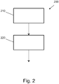
- Fig. 2 shows a method 200 according to an embodiment of the present invention.
- the method 200 for avoiding overheating of a brake of a vehicle, in particular a utility vehicle and / or a trailer, comprises a step 210 of reading in and a step 220 of determining.
- the vehicle can be a variant of an in Fig. 1 Acting embodiment of a vehicle 100 shown.
- step 210 of reading in a first temperature signal of a first brake of the brakes 112, 114, 122, 124, 132, 134, 152, 154, 162, 164 of the vehicle 100 and a second temperature signal of a second brake of the brakes 112, 114, 122 , 124, 132, 134, 152, 154, 162, 164 of the vehicle 100 are read in.
- an error state is determined using the temperature signals.
- a fault condition is determined when one of the brakes 112, 114, 122, 124, 132, 134, 152, 154, 162, 164 of the vehicle 100 becomes hot.
- the absolute measured Temperature are compared with a threshold value or comparison or reference value in order to detect an error condition.
- a brake is identified if the temperature deviates from the mean of all brakes by more than a defined tolerance range.
- the brake concerned is not actuated during braking processes below a defined braking delay. If the required deceleration exceeds the defined deceleration threshold value, for example in the event of an emergency stop or full braking, all brakes are actuated regardless of a detected fault condition.
- an acoustic signal and, additionally or alternatively, an optical signal are output in one embodiment.
- the error status is transmitted to an infrastructure facility for service purposes, for example for maintenance purposes or for the procurement of spare parts. This can be done in parallel to the transmission of other parameters of an electronic logbook.
- a further method step can be provided in order to eliminate or reduce the error state.
- the braking request on the brake concerned can be increased, for example, in order to free up a jamming guide again.
- the brake concerned can be actuated when the vehicle 100 is at a standstill, in particular repeatedly actuated, in order to bring about a movement of the moving parts of the brake without braking torque and thus to achieve a fault-free state of the brake again.
Landscapes
- Engineering & Computer Science (AREA)
- Mechanical Engineering (AREA)
- Transportation (AREA)
- General Engineering & Computer Science (AREA)
- Physics & Mathematics (AREA)
- General Physics & Mathematics (AREA)
- Acoustics & Sound (AREA)
- Valves And Accessory Devices For Braking Systems (AREA)
- Braking Arrangements (AREA)
- Regulating Braking Force (AREA)
Applications Claiming Priority (2)
| Application Number | Priority Date | Filing Date | Title |
|---|---|---|---|
| DE102015105862.6A DE102015105862A1 (de) | 2015-04-17 | 2015-04-17 | Verfahren zur Erhöhung der Betriebssicherheit thermisch belasteter Funktionsteile einer Scheibenbremse |
| PCT/EP2016/058335 WO2016166277A1 (de) | 2015-04-17 | 2016-04-15 | Verfahren und steuergerät zum vermeiden von überhitzen einer bremse eines fahrzeugs |
Publications (2)
| Publication Number | Publication Date |
|---|---|
| EP3283341A1 EP3283341A1 (de) | 2018-02-21 |
| EP3283341B1 true EP3283341B1 (de) | 2021-03-03 |
Family
ID=55754296
Family Applications (2)
| Application Number | Title | Priority Date | Filing Date |
|---|---|---|---|
| EP16716574.5A Active EP3283341B1 (de) | 2015-04-17 | 2016-04-15 | Verfahren und steuergerät zum vermeiden von überhitzen einer bremse eines fahrzeugs |
| EP16716865.7A Active EP3283342B1 (de) | 2015-04-17 | 2016-04-15 | Verfahren zum erhöhen der betriebssicherheit thermisch belasteter funktionsteile einer bremse eines fahrzeugs |
Family Applications After (1)
| Application Number | Title | Priority Date | Filing Date |
|---|---|---|---|
| EP16716865.7A Active EP3283342B1 (de) | 2015-04-17 | 2016-04-15 | Verfahren zum erhöhen der betriebssicherheit thermisch belasteter funktionsteile einer bremse eines fahrzeugs |
Country Status (9)
| Country | Link |
|---|---|
| US (2) | US10661774B2 (enExample) |
| EP (2) | EP3283341B1 (enExample) |
| JP (2) | JP6734863B2 (enExample) |
| KR (2) | KR102534552B1 (enExample) |
| CN (2) | CN107636342B (enExample) |
| BR (2) | BR112017022007A2 (enExample) |
| DE (1) | DE102015105862A1 (enExample) |
| RU (2) | RU2682434C1 (enExample) |
| WO (2) | WO2016166278A1 (enExample) |
Families Citing this family (29)
| Publication number | Priority date | Publication date | Assignee | Title |
|---|---|---|---|---|
| EP3379222B1 (en) | 2017-03-22 | 2020-12-30 | Methode Electronics Malta Ltd. | Magnetoelastic based sensor assembly |
| DE102017218675A1 (de) * | 2017-04-27 | 2018-10-31 | Robert Bosch Gmbh | Kombinierte Erfassung eines Verschleißes von Komponenten einer Bremsanlage, insbesondere eines Kraftfahrzeugs |
| US20190009831A1 (en) * | 2017-07-07 | 2019-01-10 | International Business Machines Corporation | Actively deployable and retractable fender skirts for increased fuel efficiency |
| US10539200B2 (en) * | 2017-09-27 | 2020-01-21 | Robert Bosch Gmbh | Sound-based brake wear detection for vehicle braking systems |
| US10670479B2 (en) | 2018-02-27 | 2020-06-02 | Methode Electronics, Inc. | Towing systems and methods using magnetic field sensing |
| US11491832B2 (en) | 2018-02-27 | 2022-11-08 | Methode Electronics, Inc. | Towing systems and methods using magnetic field sensing |
| US11084342B2 (en) | 2018-02-27 | 2021-08-10 | Methode Electronics, Inc. | Towing systems and methods using magnetic field sensing |
| US11221262B2 (en) | 2018-02-27 | 2022-01-11 | Methode Electronics, Inc. | Towing systems and methods using magnetic field sensing |
| US11014417B2 (en) | 2018-02-27 | 2021-05-25 | Methode Electronics, Inc. | Towing systems and methods using magnetic field sensing |
| US11135882B2 (en) | 2018-02-27 | 2021-10-05 | Methode Electronics, Inc. | Towing systems and methods using magnetic field sensing |
| US12197963B2 (en) * | 2018-03-02 | 2025-01-14 | Sumitomo Electric Industries, Ltd. | On-vehicle control device, control system, control method, and control program |
| JP7053359B2 (ja) * | 2018-04-23 | 2022-04-12 | 株式会社デンソー | 異常検知装置 |
| US11383689B2 (en) | 2018-05-23 | 2022-07-12 | Haldex Brake Products Corporation | Brake monitoring system with temperature monitoring |
| US10767717B2 (en) * | 2018-08-01 | 2020-09-08 | Bendix Commercial Vehicle Systems Llc | Method for using brake pad information in braking applications |
| US11938909B2 (en) * | 2018-09-13 | 2024-03-26 | Volvo Truck Corporation | Operating a vehicle comprising vehicle retarding subsystem |
| US11047439B2 (en) * | 2019-01-23 | 2021-06-29 | GM Global Technology Operations LLC | Intelligent brake system health monitoring |
| BR102019015930A2 (pt) * | 2019-08-01 | 2020-08-25 | Toigo Importadora E Distribuidora De Sistemas Automotivos Ltda | sistema centralizado de resfriamento de freios, rodas, pneus e rolamentos de veículos |
| DE102020100274A1 (de) * | 2020-01-09 | 2021-07-15 | Knorr-Bremse Systeme für Nutzfahrzeuge GmbH | Verfahren zur Fehlererkennung in einer Bremsanlage eines Kraftfahrzeugs und Kraftfahrzeug-Bremssystem |
| JP7322828B2 (ja) * | 2020-07-06 | 2023-08-08 | 株式会社デンソー | ブレーキ異常判定装置 |
| CN111959471A (zh) * | 2020-08-21 | 2020-11-20 | 上海拿森汽车电子有限公司 | 一种基于解耦式电子助力器的制动力补偿方法和装置 |
| DE102020129799A1 (de) * | 2020-11-11 | 2022-05-12 | Mando Corporation | Bremssystem und Verfahren zum Steuern eines Bremssystems |
| US11938911B2 (en) * | 2021-04-08 | 2024-03-26 | Arvinmeritor Technology, Llc | Brake system and method of monitoring |
| EP4166398B1 (en) * | 2021-10-15 | 2025-07-16 | KNORR-BREMSE Systeme für Nutzfahrzeuge GmbH | Method for controlling a multitude of braking means and braking system of a vehicle |
| US20230234548A1 (en) * | 2022-01-26 | 2023-07-27 | Kinetiq, Llc | System for monitoring a towable trailer and method of detecting potential thermal events |
| WO2024078707A1 (en) * | 2022-10-11 | 2024-04-18 | Volvo Truck Corporation | Method for controlling braking of vehicle |
| DE102022211554A1 (de) * | 2022-11-01 | 2024-05-02 | Stellantis Auto Sas | Verfahren zur emissionsarmen Bremssteuerung eines Kraftfahrzeugs sowie ein Kraftfahrzeug, das nach einem derartigen Verfahren bettreibbar ist |
| DE102023205788A1 (de) * | 2023-06-21 | 2024-12-24 | Continental Automotive Technologies GmbH | Verfahren und Vorrichtung zum Ermitteln der Temperatur einer Bremse eines Fahrzeugs |
| US12344215B2 (en) | 2023-08-07 | 2025-07-01 | Ford Global Technologies, Llc | System and method for automatically detecting a dragging brake |
| DE102025000442A1 (de) | 2025-02-05 | 2025-03-27 | Mercedes-Benz Group AG | Temperaturwarnung für Betriebsbremsanlage in einem Kraftfahrzeug |
Family Cites Families (23)
| Publication number | Priority date | Publication date | Assignee | Title |
|---|---|---|---|---|
| JPS6343974U (enExample) * | 1986-09-09 | 1988-03-24 | ||
| DE3930572A1 (de) * | 1989-09-13 | 1991-03-14 | Wabco Westinghouse Fahrzeug | Verfahren zur ueberschlaegigen ermittlung der mittleren temperatur eines bauteils einer bremseinrichtung |
| DE4431045C2 (de) * | 1994-09-01 | 1999-08-05 | Bosch Gmbh Robert | Sensoranordnung zur gemeinsamen Messung zweier Größen |
| JPH08156774A (ja) * | 1994-12-06 | 1996-06-18 | Nabco Ltd | ブレーキ制御方法 |
| JP3761939B2 (ja) * | 1995-10-13 | 2006-03-29 | 日野自動車株式会社 | ブレーキ警報装置 |
| CN1147408C (zh) * | 1997-05-16 | 2004-04-28 | 日野自动车工业株式会社 | 制动器警报装置 |
| CN1199682A (zh) * | 1997-05-16 | 1998-11-25 | 日野自动车工业株式会社 | 制动器警报装置 |
| EP1307375B1 (en) * | 2000-08-04 | 2010-01-13 | Meggitt Aerospace Limited | Brake condition monitoring |
| US6680672B2 (en) * | 2001-02-08 | 2004-01-20 | Volvo Trucks North America, Inc. | Vehicle diagnostic system |
| CN2475637Y (zh) * | 2001-03-09 | 2002-02-06 | 西安交通大学 | 降低制动盘温度的全自动控温保护装置 |
| US7009508B2 (en) * | 2002-08-12 | 2006-03-07 | Caterpillar Inc. | Method and apparatus for determining a brake overheating condition |
| DE10243127B4 (de) | 2002-09-17 | 2019-04-18 | Knorr-Bremse Systeme für Nutzfahrzeuge GmbH | Sensorvorrichtung zur Erfassung der Drehzahl eines Fahrzeugrades |
| JP2004197895A (ja) * | 2002-12-20 | 2004-07-15 | Nissan Diesel Motor Co Ltd | ブレーキ故障診断装置 |
| DE102006036280B3 (de) * | 2006-08-03 | 2008-01-31 | Knorr-Bremse Systeme für Nutzfahrzeuge GmbH | Verfahren zur Bremsdruckverteilung auf die Achsen eines Fahrzeugs |
| WO2008113666A1 (de) * | 2007-03-16 | 2008-09-25 | Continental Teves Ag & Co. Ohg | Verfahren und vorrichtung zur stabilisierung eines einspurigen kraftfahrzeugs |
| WO2010003244A1 (en) * | 2008-07-10 | 2010-01-14 | Nbs Innovative Solutions Ltd. | Vehicle brake monitoring system and method |
| US7877216B2 (en) * | 2008-07-30 | 2011-01-25 | Honeywell International Inc. | Method, system, and apparatus for friction pad wear and brake condition monitoring |
| US8380418B2 (en) * | 2009-08-26 | 2013-02-19 | GM Global Technology Operations LLC | Method for maintaining a brake rotor |
| FR2965873B1 (fr) * | 2010-10-06 | 2012-11-30 | Peugeot Citroen Automobiles Sa | Procede et dispositif pour la detection d'une surchauffe transitoire locale dans un composant d'un systeme de freinage |
| US8594900B2 (en) * | 2011-08-04 | 2013-11-26 | Motor Coach Industries Limited | Wheel end condition detection |
| US8717158B2 (en) * | 2012-06-11 | 2014-05-06 | Caterpillar Inc. | Braking intensity display |
| RU2513439C1 (ru) * | 2012-09-26 | 2014-04-20 | Сергей Евгеньевич Бузников | Способ предотвращения аварийного перегрева шин и тормозов автомобиля и система для его осуществления |
| GB201307308D0 (en) * | 2013-04-23 | 2013-05-29 | Haldex Brake Products Ltd | A method of, and apparatus for, controlling the speed of a vehicle |
-
2015
- 2015-04-17 DE DE102015105862.6A patent/DE102015105862A1/de active Pending
-
2016
- 2016-04-15 RU RU2017139801A patent/RU2682434C1/ru active
- 2016-04-15 WO PCT/EP2016/058336 patent/WO2016166278A1/de not_active Ceased
- 2016-04-15 KR KR1020177033082A patent/KR102534552B1/ko active Active
- 2016-04-15 EP EP16716574.5A patent/EP3283341B1/de active Active
- 2016-04-15 RU RU2017139803A patent/RU2700521C2/ru active
- 2016-04-15 JP JP2017550570A patent/JP6734863B2/ja not_active Expired - Fee Related
- 2016-04-15 JP JP2017550571A patent/JP6734864B2/ja not_active Expired - Fee Related
- 2016-04-15 KR KR1020177032626A patent/KR102550480B1/ko active Active
- 2016-04-15 CN CN201680029826.8A patent/CN107636342B/zh active Active
- 2016-04-15 BR BR112017022007-5A patent/BR112017022007A2/pt not_active Application Discontinuation
- 2016-04-15 CN CN201680029804.1A patent/CN107667046B/zh active Active
- 2016-04-15 WO PCT/EP2016/058335 patent/WO2016166277A1/de not_active Ceased
- 2016-04-15 EP EP16716865.7A patent/EP3283342B1/de active Active
- 2016-04-15 BR BR112017021314-1A patent/BR112017021314A2/pt not_active Application Discontinuation
-
2017
- 2017-10-16 US US15/784,827 patent/US10661774B2/en active Active
- 2017-10-16 US US15/784,817 patent/US10654462B2/en active Active
Non-Patent Citations (1)
| Title |
|---|
| None * |
Also Published As
| Publication number | Publication date |
|---|---|
| CN107636342B (zh) | 2019-11-26 |
| RU2017139803A (ru) | 2019-05-17 |
| KR102550480B1 (ko) | 2023-06-30 |
| CN107667046B (zh) | 2021-06-08 |
| RU2682434C1 (ru) | 2019-03-19 |
| US10654462B2 (en) | 2020-05-19 |
| EP3283342B1 (de) | 2022-01-05 |
| JP6734863B2 (ja) | 2020-08-05 |
| EP3283342A1 (de) | 2018-02-21 |
| BR112017022007A2 (pt) | 2018-07-03 |
| US20180037209A1 (en) | 2018-02-08 |
| KR20170137825A (ko) | 2017-12-13 |
| US20180037210A1 (en) | 2018-02-08 |
| US10661774B2 (en) | 2020-05-26 |
| JP6734864B2 (ja) | 2020-08-05 |
| JP2018516195A (ja) | 2018-06-21 |
| RU2700521C2 (ru) | 2019-09-17 |
| WO2016166277A1 (de) | 2016-10-20 |
| DE102015105862A1 (de) | 2016-10-20 |
| RU2017139803A3 (enExample) | 2019-05-17 |
| BR112017021314A2 (pt) | 2018-06-26 |
| EP3283341A1 (de) | 2018-02-21 |
| CN107667046A (zh) | 2018-02-06 |
| WO2016166278A1 (de) | 2016-10-20 |
| KR20170137888A (ko) | 2017-12-13 |
| KR102534552B1 (ko) | 2023-05-18 |
| JP2018516795A (ja) | 2018-06-28 |
| CN107636342A (zh) | 2018-01-26 |
Similar Documents
| Publication | Publication Date | Title |
|---|---|---|
| EP3283341B1 (de) | Verfahren und steuergerät zum vermeiden von überhitzen einer bremse eines fahrzeugs | |
| EP0189083B1 (de) | Einrichtung zum Messen und/oder Regeln des Verschleisses eines Bauteils | |
| EP0189082B1 (de) | Einrichtung zum Messen und/oder Regeln einer Bremskraft und/oder eines Bremsmomentes | |
| DE10233844B4 (de) | Vorrichtung und Verfahren zur Überwachung des Funktions- und/oder Verschleißzustandes von Bremsbelägen und Bremsscheiben einer Fahrzeugbremse | |
| DE69810483T2 (de) | Verfahren und einrichtung zur erkennung einer falsch eingestellten spielnachstellung für bremsen | |
| EP2057386B1 (de) | TEMPERATUR- UND VERSCHLEIßSENSOR FÜR BREMS- ODER KUPPLUNGSEINRICHTUNGEN | |
| DE102010044899B4 (de) | Verfahren zur Vorhersage der Temperatur eines Radlagers eines Rades eines Fahrzeugs | |
| DE102014119024B4 (de) | System und Verfahren zur Warnung vor Verschleiß eines Bremsreibbelages eines Fahrzeuges | |
| EP2720919B1 (de) | Aktuatorsystem und betriebsverfahren für ein aktuatorsystem | |
| WO2003080415A1 (de) | Elektrisch betätigbare fahrzeugbremse und verfahren zur steuerung einer elektrisch betätigbaren fahrzeugbremse | |
| DE102019134292A1 (de) | Intelligente zustandsüberwachung des bremssystems | |
| DE102012108395A1 (de) | Verfahren zur Kalkulation einer Fahrempfehlung eines Schienenfahrzeugs, Assistenzsystem eines Schienenfahrzeugs und Schienenfahrzeug | |
| EP2520817A1 (de) | Verfahren und Vorrichtung zum Überwachen des Bremsbelagverschleißes und Lüftspiels einer Betriebsbremse in Kraftfahrzeugen | |
| DE4235364C2 (de) | Verfahren zum Erfassen der Temperatur einer Scheibenbremse | |
| DE102021104800A1 (de) | Verfahren zur Bestimmung einer optimalen oder maximal zulässigen Geschwindigkeit eines Schienenfahrzeugs | |
| DE102021104799A1 (de) | Verfahren und Vorrichtung zur Überwachung und Beeinflussung des thermischen Zustands eines Reibungsbremssystems eines Schienenfahrzeugs | |
| EP0818372A2 (de) | System für die Antriebs- und Bremssteuerung eines Schienenfahrzeuges | |
| DE102018215013B4 (de) | Belastungsbestimmungsverfahren für eine Fahrzeugkomponente eines Fahrzeugs, Steuereinheit und Fahrzeug | |
| DE102024115787A1 (de) | Verfahren zur Temperaturregelung einer Steuereinrichtung eines Fahrzeugs, Steuereinrichtung, Fahrzeug und Computerprogramm | |
| WO2018177834A1 (de) | Scheibenbremsvorrichtung eines fahrzeugs mit temperaturerfassung der bremsscheibe | |
| DE9218256U1 (de) | Vorrichtung zum Erfassen der Temperatur einer Scheibenbremse |
Legal Events
| Date | Code | Title | Description |
|---|---|---|---|
| STAA | Information on the status of an ep patent application or granted ep patent |
Free format text: STATUS: THE INTERNATIONAL PUBLICATION HAS BEEN MADE |
|
| PUAI | Public reference made under article 153(3) epc to a published international application that has entered the european phase |
Free format text: ORIGINAL CODE: 0009012 |
|
| STAA | Information on the status of an ep patent application or granted ep patent |
Free format text: STATUS: REQUEST FOR EXAMINATION WAS MADE |
|
| 17P | Request for examination filed |
Effective date: 20171117 |
|
| AK | Designated contracting states |
Kind code of ref document: A1 Designated state(s): AL AT BE BG CH CY CZ DE DK EE ES FI FR GB GR HR HU IE IS IT LI LT LU LV MC MK MT NL NO PL PT RO RS SE SI SK SM TR |
|
| AX | Request for extension of the european patent |
Extension state: BA ME |
|
| DAV | Request for validation of the european patent (deleted) | ||
| DAX | Request for extension of the european patent (deleted) | ||
| GRAP | Despatch of communication of intention to grant a patent |
Free format text: ORIGINAL CODE: EPIDOSNIGR1 |
|
| STAA | Information on the status of an ep patent application or granted ep patent |
Free format text: STATUS: GRANT OF PATENT IS INTENDED |
|
| INTG | Intention to grant announced |
Effective date: 20200930 |
|
| GRAS | Grant fee paid |
Free format text: ORIGINAL CODE: EPIDOSNIGR3 |
|
| GRAA | (expected) grant |
Free format text: ORIGINAL CODE: 0009210 |
|
| STAA | Information on the status of an ep patent application or granted ep patent |
Free format text: STATUS: THE PATENT HAS BEEN GRANTED |
|
| AK | Designated contracting states |
Kind code of ref document: B1 Designated state(s): AL AT BE BG CH CY CZ DE DK EE ES FI FR GB GR HR HU IE IS IT LI LT LU LV MC MK MT NL NO PL PT RO RS SE SI SK SM TR |
|
| REG | Reference to a national code |
Ref country code: GB Ref legal event code: FG4D Free format text: NOT ENGLISH |
|
| REG | Reference to a national code |
Ref country code: CH Ref legal event code: EP Ref country code: AT Ref legal event code: REF Ref document number: 1366899 Country of ref document: AT Kind code of ref document: T Effective date: 20210315 |
|
| REG | Reference to a national code |
Ref country code: DE Ref legal event code: R096 Ref document number: 502016012506 Country of ref document: DE |
|
| REG | Reference to a national code |
Ref country code: IE Ref legal event code: FG4D Free format text: LANGUAGE OF EP DOCUMENT: GERMAN |
|
| REG | Reference to a national code |
Ref country code: NL Ref legal event code: FP |
|
| REG | Reference to a national code |
Ref country code: SE Ref legal event code: TRGR |
|
| REG | Reference to a national code |
Ref country code: LT Ref legal event code: MG9D |
|
| PG25 | Lapsed in a contracting state [announced via postgrant information from national office to epo] |
Ref country code: BG Free format text: LAPSE BECAUSE OF FAILURE TO SUBMIT A TRANSLATION OF THE DESCRIPTION OR TO PAY THE FEE WITHIN THE PRESCRIBED TIME-LIMIT Effective date: 20210603 Ref country code: LT Free format text: LAPSE BECAUSE OF FAILURE TO SUBMIT A TRANSLATION OF THE DESCRIPTION OR TO PAY THE FEE WITHIN THE PRESCRIBED TIME-LIMIT Effective date: 20210303 Ref country code: NO Free format text: LAPSE BECAUSE OF FAILURE TO SUBMIT A TRANSLATION OF THE DESCRIPTION OR TO PAY THE FEE WITHIN THE PRESCRIBED TIME-LIMIT Effective date: 20210603 Ref country code: HR Free format text: LAPSE BECAUSE OF FAILURE TO SUBMIT A TRANSLATION OF THE DESCRIPTION OR TO PAY THE FEE WITHIN THE PRESCRIBED TIME-LIMIT Effective date: 20210303 Ref country code: GR Free format text: LAPSE BECAUSE OF FAILURE TO SUBMIT A TRANSLATION OF THE DESCRIPTION OR TO PAY THE FEE WITHIN THE PRESCRIBED TIME-LIMIT Effective date: 20210604 Ref country code: FI Free format text: LAPSE BECAUSE OF FAILURE TO SUBMIT A TRANSLATION OF THE DESCRIPTION OR TO PAY THE FEE WITHIN THE PRESCRIBED TIME-LIMIT Effective date: 20210303 |
|
| PG25 | Lapsed in a contracting state [announced via postgrant information from national office to epo] |
Ref country code: LV Free format text: LAPSE BECAUSE OF FAILURE TO SUBMIT A TRANSLATION OF THE DESCRIPTION OR TO PAY THE FEE WITHIN THE PRESCRIBED TIME-LIMIT Effective date: 20210303 Ref country code: RS Free format text: LAPSE BECAUSE OF FAILURE TO SUBMIT A TRANSLATION OF THE DESCRIPTION OR TO PAY THE FEE WITHIN THE PRESCRIBED TIME-LIMIT Effective date: 20210303 Ref country code: PL Free format text: LAPSE BECAUSE OF FAILURE TO SUBMIT A TRANSLATION OF THE DESCRIPTION OR TO PAY THE FEE WITHIN THE PRESCRIBED TIME-LIMIT Effective date: 20210303 |
|
| PG25 | Lapsed in a contracting state [announced via postgrant information from national office to epo] |
Ref country code: CZ Free format text: LAPSE BECAUSE OF FAILURE TO SUBMIT A TRANSLATION OF THE DESCRIPTION OR TO PAY THE FEE WITHIN THE PRESCRIBED TIME-LIMIT Effective date: 20210303 Ref country code: EE Free format text: LAPSE BECAUSE OF FAILURE TO SUBMIT A TRANSLATION OF THE DESCRIPTION OR TO PAY THE FEE WITHIN THE PRESCRIBED TIME-LIMIT Effective date: 20210303 Ref country code: SM Free format text: LAPSE BECAUSE OF FAILURE TO SUBMIT A TRANSLATION OF THE DESCRIPTION OR TO PAY THE FEE WITHIN THE PRESCRIBED TIME-LIMIT Effective date: 20210303 |
|
| PG25 | Lapsed in a contracting state [announced via postgrant information from national office to epo] |
Ref country code: IS Free format text: LAPSE BECAUSE OF FAILURE TO SUBMIT A TRANSLATION OF THE DESCRIPTION OR TO PAY THE FEE WITHIN THE PRESCRIBED TIME-LIMIT Effective date: 20210703 Ref country code: RO Free format text: LAPSE BECAUSE OF FAILURE TO SUBMIT A TRANSLATION OF THE DESCRIPTION OR TO PAY THE FEE WITHIN THE PRESCRIBED TIME-LIMIT Effective date: 20210303 Ref country code: SK Free format text: LAPSE BECAUSE OF FAILURE TO SUBMIT A TRANSLATION OF THE DESCRIPTION OR TO PAY THE FEE WITHIN THE PRESCRIBED TIME-LIMIT Effective date: 20210303 Ref country code: PT Free format text: LAPSE BECAUSE OF FAILURE TO SUBMIT A TRANSLATION OF THE DESCRIPTION OR TO PAY THE FEE WITHIN THE PRESCRIBED TIME-LIMIT Effective date: 20210705 |
|
| REG | Reference to a national code |
Ref country code: DE Ref legal event code: R097 Ref document number: 502016012506 Country of ref document: DE |
|
| PG25 | Lapsed in a contracting state [announced via postgrant information from national office to epo] |
Ref country code: LU Free format text: LAPSE BECAUSE OF NON-PAYMENT OF DUE FEES Effective date: 20210415 |
|
| PLBE | No opposition filed within time limit |
Free format text: ORIGINAL CODE: 0009261 |
|
| STAA | Information on the status of an ep patent application or granted ep patent |
Free format text: STATUS: NO OPPOSITION FILED WITHIN TIME LIMIT |
|
| REG | Reference to a national code |
Ref country code: BE Ref legal event code: MM Effective date: 20210430 |
|
| PG25 | Lapsed in a contracting state [announced via postgrant information from national office to epo] |
Ref country code: DK Free format text: LAPSE BECAUSE OF FAILURE TO SUBMIT A TRANSLATION OF THE DESCRIPTION OR TO PAY THE FEE WITHIN THE PRESCRIBED TIME-LIMIT Effective date: 20210303 Ref country code: MC Free format text: LAPSE BECAUSE OF FAILURE TO SUBMIT A TRANSLATION OF THE DESCRIPTION OR TO PAY THE FEE WITHIN THE PRESCRIBED TIME-LIMIT Effective date: 20210303 Ref country code: LI Free format text: LAPSE BECAUSE OF NON-PAYMENT OF DUE FEES Effective date: 20210430 Ref country code: AL Free format text: LAPSE BECAUSE OF FAILURE TO SUBMIT A TRANSLATION OF THE DESCRIPTION OR TO PAY THE FEE WITHIN THE PRESCRIBED TIME-LIMIT Effective date: 20210303 Ref country code: CH Free format text: LAPSE BECAUSE OF NON-PAYMENT OF DUE FEES Effective date: 20210430 Ref country code: ES Free format text: LAPSE BECAUSE OF FAILURE TO SUBMIT A TRANSLATION OF THE DESCRIPTION OR TO PAY THE FEE WITHIN THE PRESCRIBED TIME-LIMIT Effective date: 20210303 |
|
| 26N | No opposition filed |
Effective date: 20211206 |
|
| PG25 | Lapsed in a contracting state [announced via postgrant information from national office to epo] |
Ref country code: SI Free format text: LAPSE BECAUSE OF FAILURE TO SUBMIT A TRANSLATION OF THE DESCRIPTION OR TO PAY THE FEE WITHIN THE PRESCRIBED TIME-LIMIT Effective date: 20210303 |
|
| PG25 | Lapsed in a contracting state [announced via postgrant information from national office to epo] |
Ref country code: IE Free format text: LAPSE BECAUSE OF NON-PAYMENT OF DUE FEES Effective date: 20210415 |
|
| PG25 | Lapsed in a contracting state [announced via postgrant information from national office to epo] |
Ref country code: IS Free format text: LAPSE BECAUSE OF FAILURE TO SUBMIT A TRANSLATION OF THE DESCRIPTION OR TO PAY THE FEE WITHIN THE PRESCRIBED TIME-LIMIT Effective date: 20210703 |
|
| REG | Reference to a national code |
Ref country code: AT Ref legal event code: MM01 Ref document number: 1366899 Country of ref document: AT Kind code of ref document: T Effective date: 20210415 |
|
| PG25 | Lapsed in a contracting state [announced via postgrant information from national office to epo] |
Ref country code: BE Free format text: LAPSE BECAUSE OF NON-PAYMENT OF DUE FEES Effective date: 20210430 |
|
| PG25 | Lapsed in a contracting state [announced via postgrant information from national office to epo] |
Ref country code: AT Free format text: LAPSE BECAUSE OF NON-PAYMENT OF DUE FEES Effective date: 20210415 |
|
| PG25 | Lapsed in a contracting state [announced via postgrant information from national office to epo] |
Ref country code: HU Free format text: LAPSE BECAUSE OF FAILURE TO SUBMIT A TRANSLATION OF THE DESCRIPTION OR TO PAY THE FEE WITHIN THE PRESCRIBED TIME-LIMIT; INVALID AB INITIO Effective date: 20160415 |
|
| PG25 | Lapsed in a contracting state [announced via postgrant information from national office to epo] |
Ref country code: CY Free format text: LAPSE BECAUSE OF FAILURE TO SUBMIT A TRANSLATION OF THE DESCRIPTION OR TO PAY THE FEE WITHIN THE PRESCRIBED TIME-LIMIT Effective date: 20210303 |
|
| P01 | Opt-out of the competence of the unified patent court (upc) registered |
Effective date: 20230607 |
|
| PG25 | Lapsed in a contracting state [announced via postgrant information from national office to epo] |
Ref country code: MK Free format text: LAPSE BECAUSE OF FAILURE TO SUBMIT A TRANSLATION OF THE DESCRIPTION OR TO PAY THE FEE WITHIN THE PRESCRIBED TIME-LIMIT Effective date: 20210303 |
|
| PGFP | Annual fee paid to national office [announced via postgrant information from national office to epo] |
Ref country code: NL Payment date: 20240425 Year of fee payment: 9 |
|
| PG25 | Lapsed in a contracting state [announced via postgrant information from national office to epo] |
Ref country code: TR Free format text: LAPSE BECAUSE OF FAILURE TO SUBMIT A TRANSLATION OF THE DESCRIPTION OR TO PAY THE FEE WITHIN THE PRESCRIBED TIME-LIMIT Effective date: 20210303 |
|
| PGFP | Annual fee paid to national office [announced via postgrant information from national office to epo] |
Ref country code: IT Payment date: 20240423 Year of fee payment: 9 |
|
| PG25 | Lapsed in a contracting state [announced via postgrant information from national office to epo] |
Ref country code: MT Free format text: LAPSE BECAUSE OF FAILURE TO SUBMIT A TRANSLATION OF THE DESCRIPTION OR TO PAY THE FEE WITHIN THE PRESCRIBED TIME-LIMIT Effective date: 20210303 |
|
| PGFP | Annual fee paid to national office [announced via postgrant information from national office to epo] |
Ref country code: DE Payment date: 20250428 Year of fee payment: 10 |
|
| PGFP | Annual fee paid to national office [announced via postgrant information from national office to epo] |
Ref country code: GB Payment date: 20250422 Year of fee payment: 10 |
|
| PGFP | Annual fee paid to national office [announced via postgrant information from national office to epo] |
Ref country code: FR Payment date: 20250424 Year of fee payment: 10 |
|
| PGFP | Annual fee paid to national office [announced via postgrant information from national office to epo] |
Ref country code: SE Payment date: 20250424 Year of fee payment: 10 |
|
| REG | Reference to a national code |
Ref country code: NL Ref legal event code: MM Effective date: 20250501 |