EP3283025B1 - Vorrichtung zur herstellung eines vakuums mithilfe des venturi-effekts - Google Patents
Vorrichtung zur herstellung eines vakuums mithilfe des venturi-effekts Download PDFInfo
- Publication number
- EP3283025B1 EP3283025B1 EP16780599.3A EP16780599A EP3283025B1 EP 3283025 B1 EP3283025 B1 EP 3283025B1 EP 16780599 A EP16780599 A EP 16780599A EP 3283025 B1 EP3283025 B1 EP 3283025B1
- Authority
- EP
- European Patent Office
- Prior art keywords
- passageway
- motive
- suction
- suction chamber
- sealing member
- Prior art date
- Legal status (The legal status is an assumption and is not a legal conclusion. Google has not performed a legal analysis and makes no representation as to the accuracy of the status listed.)
- Active
Links
Images


Classifications
-
- F—MECHANICAL ENGINEERING; LIGHTING; HEATING; WEAPONS; BLASTING
- F04—POSITIVE - DISPLACEMENT MACHINES FOR LIQUIDS; PUMPS FOR LIQUIDS OR ELASTIC FLUIDS
- F04F—PUMPING OF FLUID BY DIRECT CONTACT OF ANOTHER FLUID OR BY USING INERTIA OF FLUID TO BE PUMPED; SIPHONS
- F04F5/00—Jet pumps, i.e. devices in which flow is induced by pressure drop caused by velocity of another fluid flow
- F04F5/14—Jet pumps, i.e. devices in which flow is induced by pressure drop caused by velocity of another fluid flow the inducing fluid being elastic fluid
- F04F5/16—Jet pumps, i.e. devices in which flow is induced by pressure drop caused by velocity of another fluid flow the inducing fluid being elastic fluid displacing elastic fluids
-
- F—MECHANICAL ENGINEERING; LIGHTING; HEATING; WEAPONS; BLASTING
- F04—POSITIVE - DISPLACEMENT MACHINES FOR LIQUIDS; PUMPS FOR LIQUIDS OR ELASTIC FLUIDS
- F04F—PUMPING OF FLUID BY DIRECT CONTACT OF ANOTHER FLUID OR BY USING INERTIA OF FLUID TO BE PUMPED; SIPHONS
- F04F5/00—Jet pumps, i.e. devices in which flow is induced by pressure drop caused by velocity of another fluid flow
- F04F5/44—Component parts, details, or accessories not provided for in, or of interest apart from, groups F04F5/02 - F04F5/42
- F04F5/46—Arrangements of nozzles
-
- F—MECHANICAL ENGINEERING; LIGHTING; HEATING; WEAPONS; BLASTING
- F04—POSITIVE - DISPLACEMENT MACHINES FOR LIQUIDS; PUMPS FOR LIQUIDS OR ELASTIC FLUIDS
- F04F—PUMPING OF FLUID BY DIRECT CONTACT OF ANOTHER FLUID OR BY USING INERTIA OF FLUID TO BE PUMPED; SIPHONS
- F04F5/00—Jet pumps, i.e. devices in which flow is induced by pressure drop caused by velocity of another fluid flow
- F04F5/14—Jet pumps, i.e. devices in which flow is induced by pressure drop caused by velocity of another fluid flow the inducing fluid being elastic fluid
- F04F5/16—Jet pumps, i.e. devices in which flow is induced by pressure drop caused by velocity of another fluid flow the inducing fluid being elastic fluid displacing elastic fluids
- F04F5/20—Jet pumps, i.e. devices in which flow is induced by pressure drop caused by velocity of another fluid flow the inducing fluid being elastic fluid displacing elastic fluids for evacuating
-
- F—MECHANICAL ENGINEERING; LIGHTING; HEATING; WEAPONS; BLASTING
- F04—POSITIVE - DISPLACEMENT MACHINES FOR LIQUIDS; PUMPS FOR LIQUIDS OR ELASTIC FLUIDS
- F04F—PUMPING OF FLUID BY DIRECT CONTACT OF ANOTHER FLUID OR BY USING INERTIA OF FLUID TO BE PUMPED; SIPHONS
- F04F5/00—Jet pumps, i.e. devices in which flow is induced by pressure drop caused by velocity of another fluid flow
- F04F5/44—Component parts, details, or accessories not provided for in, or of interest apart from, groups F04F5/02 - F04F5/42
- F04F5/46—Arrangements of nozzles
- F04F5/464—Arrangements of nozzles with inversion of the direction of flow
-
- F—MECHANICAL ENGINEERING; LIGHTING; HEATING; WEAPONS; BLASTING
- F04—POSITIVE - DISPLACEMENT MACHINES FOR LIQUIDS; PUMPS FOR LIQUIDS OR ELASTIC FLUIDS
- F04F—PUMPING OF FLUID BY DIRECT CONTACT OF ANOTHER FLUID OR BY USING INERTIA OF FLUID TO BE PUMPED; SIPHONS
- F04F5/00—Jet pumps, i.e. devices in which flow is induced by pressure drop caused by velocity of another fluid flow
- F04F5/44—Component parts, details, or accessories not provided for in, or of interest apart from, groups F04F5/02 - F04F5/42
- F04F5/48—Control
- F04F5/52—Control of evacuating pumps
Definitions
- This application relates to devices for producing vacuum using the Venturi effect, more particularly to such devices having increased suction flow generated with a moderate motive flow rate.
- Engines for example vehicle engines, are being downsized and boosted, which is reducing the available vacuum from the engine. This vacuum has many potential uses, including use by the vehicle brake booster.
- Vacuum pumps have a significant cost and weight penalty to the engine, their electric power consumption can require additional alternator capacity, and their inefficiency can hinder fuel economy improvement actions.
- Another solution is an aspirator that generates vacuum by creating an engine air flow path that is parallel to the throttle, referred to as an intake leak. This leak flow passes through a Venturi that generates a suction vacuum.
- the problem with the presently available aspirators is that they are limited in the amount of vacuum mass flow rate they can generate, and by the amount of engine air they consume.
- fluid means any liquid, suspension, colloid, gas, plasma, or combinations thereof.
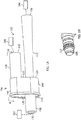
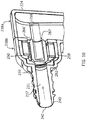
- FIGS. 1A-4 illustrate different views of a device 100 for producing vacuum using a Venturi effect.
- the device 100 may be used in an engine, for example, in a vehicle's engine (an internal combustion engine) to provide vacuum to a device requiring vacuum, such as a vehicle brake boost device, positive crankcase ventilation system, a fuel vapor canister purge device, a hydraulic and/or pneumatic valve, etc.
- Device 100 includes a housing 106 defining a suction chamber 107 in fluid communication with passageway 104 ( FIG. 2 ), which extends from the motive entrance 132 of the motive port 108 to the discharge exit 156 of the discharge port 112.
- the device 100 has at least three ports that are connectable to an engine or components connected to the engine.
- the ports include: (1) a motive port 108; (2) a suction port 110, which can connect via an optional check valve (not shown) to a device requiring vacuum 180; and (3) a discharge port 112.
- Each of these ports 108, 110, and 112 may include a connector feature 117 on an outer surface thereof for connecting the respective port to a hose or other component in the engine, as shown in FIG. 1B for the motive port 108.
- the housing 106 defining the suction chamber 107 includes a first end wall 120 proximate the motive port 108, a second end wall 122 proximate the discharge port 112 and at least one side wall 124 extending between the first and second end walls 120, 122.
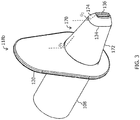
- the suction chamber when viewed in a transverse cross-section may be generally pear-shaped, i.e., having a rounded top 148 and rounded bottom 149 where the rounded top is narrower than the rounded bottom. As shown in FIG.
- the suction chamber 107 may be a two-part construction having a container 118a and a lid 118b, where the lid 118b seats within or against a rim 119 of the container 118a with a fluid-tight seal.
- the container 118b includes the suction port 110 and the discharge port 112 and the lid 118b includes the motive port 108, but is not limited thereto.
- the container could include the motive port and the lid could include the suction port and the discharge port.
- the motive port 108 defines a motive passageway 109 converging toward the suction chamber 107 and in fluid communication therewith, the discharge port 112 defines a discharge passageway 113 diverging away from the suction chamber 107 and in fluid communication therewith, and the suction port 110 defines a suction passageway 111 in fluid communication with the suction chamber 107.
- These converging and diverging sections gradually, continuously taper along the length of at least a portion of the interior passageway 109, 111, or 113.
- the motive port 108 includes an inlet end 130 having a motive entrance 132 and an outlet end 134 having a motive exit 136.
- the suction port 110 includes an inlet end 140 having a suction entrance 142 and an outlet end 144 having a suction exit 146, wherein both the motive exit 136 and the suction exit 146 exit into the suction chamber 107.
- the discharge port 112 includes an inlet end 150, proximate the suction chamber 107, having a discharge entrance 152, and an outlet end 154, distal from the suction chamber 107, having a discharge exit 156.
- the suction passageway 111 enters the suction chamber 107 at a position that generates about a 180 degree change in the direction of the suction flow from the suction passageway 111 to the discharge passageway 113. Accordingly, the suction port 110 is generally parallel to the discharge port 112.
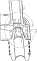
- the outlet end 134 of the motive passageway 109 is generally aligned with and spaced apart from the discharge entrance 152 at the inlet end 150 of the discharge passageway 113 to define a Venturi gap 160.
- the Venturi gap 160 means the lineal distance V D between the motive exit 136 and the discharge entrance 152.
- the motive exit 136 has a first corner radius 162 inside the motive passageway 109, and the discharge entrance 152 is generally flush with the second end wall 122 of the suction chamber 107 and transitions thereto with a second corner radius 164 that is larger than the first corner radius 162.
- the motive passageway 109 terminates in a spout 170 protruding into the suction chamber 107, which has an internal width W I as labeled in FIG. 4 of about a 10 mm to about a 25 mm, or more preferably about 15 mm to about 20 mm.
- the spout 170 is disposed spaced apart from all one or more sidewalls 124 of the suction chamber 107, thereby providing suction flow around the entirety of an exterior surface 172 of the spout 170.
- the exterior surface 172 is generally frustoconical and converges toward the outlet end 134 of the motive passageway 109 with a first converging angle ⁇ 1 (labeled in FIG. 3 ).
- the exterior surface 172 may transition into a chamfer 174 more proximate the outlet end 134 than the first end wall 120.
- the chamfer 174 has a second converging angle ⁇ 2 that is greater than the first converging angle ⁇ 1 .
- the chamber 174 as shown in FIG. 3 changes the generally circular frustoconical exterior surface 172 to a generally more rounded-rectangular or elliptical frustoconical shape.
- the bottom of the suction chamber 107 below the spout 170 may have a generally rounded interior bottom.
- the shape of the exterior surface 172, and/or the chamfer 174, and the interior bottom of the suction chamber 107 is advantageous to direct suction flow toward the discharge entrance 152 and do so with minimal disturbance/interference in the flow.
- the spout 170 has a wall thickness T that may be about 0.5 mm to about 5 mm, or about 0.5 to about 3 mm, or about 1.0 mm to about 2.0 mm depending upon the material selected for the construction of the device 100.
- the cross-sectional area of the motive exit 136 is smaller than the cross-sectional area of the discharge entrance 152, this difference is referred to as the offset.
- the offset of the cross-sectional areas may vary depending upon the parameters of the system into which the device 100 is to be incorporated. In one embodiment, the offset may be in the range of about 0.1 mm to about 2.0 mm, or more preferably in a range of about 0.3 mm to about 1.5 mm. In another embodiment, the offset may be in the range of about 0.5 m to about 1.2 mm, or more preferably in a range of about 0.7 to about 1.0 mm.
- the vehicle manufacturer When device 100 is for use in a vehicle engine, the vehicle manufacturer typically selects the size of both the motive port 108 and discharge port 112 based on the tubing/hose size available for connection of the aspirator to the engine or components thereof. Additionally, the vehicle manufacturer typically selects the maximum motive flow rate available for use in the system, which in turn will dictate the area of the interior opening defined at the motive outlet end 134, i.e., the motive exit 136. Working within these constraints, the disclosed devices 100 significantly reduce the compromise between the desire to produce high suction flow rates at moderate motive flow rates provided under boost conditions of an engine.
- This reduction in the compromise is accomplished by changing the configuration of the orientation of the suction port 110, the suction chamber 107, including its internal width and shape, the spout of the motive port 108, the offset of the motive exit and the discharge entrance, adding the corner radii to the motive exit and/or the discharge entrance, and varying the Venturi gap V D .
- the device 100 in particular the suction port 110, is connected to a device requiring vacuum (see FIG. 1 ), and the device 100 creates vacuum for said device by the flow of fluid, typically air, through passageway 104, extending generally the length of the device, and the Venturi gap 152 (labeled in FIG. 4 ) defined thereby within the suction chamber 107.
- the motive port 108 is connected for fluid communication of its motive passageway with a source of boost pressure and the discharge passageway is connected for fluid communication of its discharge passageway with atmospheric pressure, which is less than the boost pressure.
- the device 100 may be referred to as an "ejector.”
- the motive port 108 may be connected to atmospheric pressure and the discharge port may be connected to a source of pressure that is less than atmospheric pressure.
- the device 100 may be referred to as an "aspirator.”
- the flow of fluid e.g., air
- the reduction in area causes the velocity of the air to increase. Because this is an enclosed space the laws of fluid mechanics state that the static pressure must decrease when the fluid velocity increases.
- the minimum cross sectional area of the converging motive passageway abuts the Venturi gap.
- the discharge entrance and diverging discharge passageway which is either a straight cone, a parabolic profile, or a hyperbolic profile.
- the discharge passageway can continue as a straight, parabolic profile, or hyperbolic profile cone until it joins the discharge exit, or it can transition to a simple cylindrical or tapered passage before reaching the discharge exit.
- the area of the Venturi gap is increased by increasing the perimeter of the discharge entrance 152 without increasing the overall inner dimension of the first motive passageway 109 (preferably with no increase in the mass flow rate).
- the motive exit 136 and the discharge entrance 152 are non-circular as explained in co-owned U.S. Patent Application No. 14/294,727, filed on June 3, 2014 because a non-circular shaped having the same area as a passageway with a circular cross-section is an increase in the ratio of perimeter to area.
- the motive passageway 109 and the discharge passageway 113 both converge in cross-sectional area toward the suction chamber 107 as a hyperbolic or parabolic function.
- the motive entrance 132 and the discharge exit 156 may be the same shape or different and may be generally rectangular, elliptical or circular.
- motive entrance 132 and the discharge exit 156 are depicted as circular, but the motive exit 136 and the discharge entrance 152, i.e., the interior shape of each opening, are rectangularly- or elliptically-shaped. Other polygonal shapes are also possible, and the devices should not be interpreted to be limited to rectangular or elliptical interior shapes.
- the interior of the motive passageway 109 and/or the discharge passageway may be constructed to have the same general shape.
- the shape illustrated in FIG. 7 of the co-pending application identified above begins at the motive inlet end 130 as a circular opening having an area A 1 and gradually, continuously transitions, as a hyperbolic function, to an ellipse opening at the motive exit 136 that has an area A 2 , which is smaller than A 1 .
- the circular opening at the motive inlet end 130 is connected to the ellipse-shaped motive exit 136 by hyperbola lines that provide the advantage of flow lines at the motive exit 136 being parallel to one another.
- the suction passageway 111 defined by the suction port 110 may be a generally cylindrical passage of constant dimension(s) as shown in FIG. 1 , or it may gradually, continuously taper as a cone or according to a hyperbolic or parabolic function along its length converging toward the suction chamber 107.
- FIGS. 5-9 a second device for producing vacuum using a Venturi effect, generally designated 200, is illustrated that has the same or similar features as described above for the embodiment disclosed in FIGS. 1A-4 .
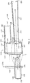
- Device 200 differs from device 100 in the inclusion of a solenoid valve 260 to control the flow of fluid through the suction port 210.
- a solenoid valve 260 to control the flow of fluid through the suction port 210.
- the solenoid valve 260 is seated within the suction passageway 211 to control the flow of fluid therethrough.
- the solenoid valve 260 may be seated in a receptacle 258 defined in the lid 218b, in the container 218a, or in a portion of both thereof and includes a spring 259 seated within the chamber 207, in particular against the interior surface of the second end wall 222, and connected to a sealing member 266 of the solenoid valve 260.
- the solenoid valve 260 is seated in a receptacle 258 defined in the lid 218b.
- the receptacle 258 has a seal seat integral therewith or a seal seat 262 mounted therein to mate a sealing member 266 of the solenoid valve 260 therewith in a fluid-tight engagement.
- the seal seat 262 defines a bore 274 (see FIG. 7 ) therethrough in fluid alignment with the suction passageway 211.
- the bore 274 is smaller than the bore 278 in a first core 264 of the solenoid valve 260 to seal the suction passageway 211 when the solenoid valve is in a closed position.
- the seal seat 262 may also include a contoured or beveled face 276 that the sealing member 266 seats against.
- the solenoid valve 260 from left to right in FIG. 7 , includes a first core 264, the sealing member 266, a coil 270 wound on a bobbin 268, and a second core 272.
- the first core 264, the second core 272, and the sealing member 266 are all made from materials that readily conduct magnetic flux.
- the first core 264 is generally cup-shaped having a bottom 277 defining a bore 278 therethrough.
- the bore 278 includes a sealing member-receiving portion 278 having a diameter larger than an outer dimension or outer diameter of the sealing member 266, such that the sealing member 266 is translatable at least partially therethrough into and out of engagement with the seal seat 262, and a plurality of flow channels 280 radiating radially outward from the sealing member-receiving portion 278, which may be best illustrated in FIG. 8 .
- the flow channels 280 enable fluid flow around the sealing member 266 and into the chamber 207 defined by the housing 206.
- the second core 272 is generally a planar disk mateable to the first core 264 to define a housing for the sealing member 266 and the coil 270 wound on the bobbin 268.
- first core may be a generally planar disk and the second core may be generally cup-shaped.
- first and second cores may each be generally cup-shaped and mate together to define a housing.
- there may be two generally flat cores, one made as 272, the other made as the bottom of 264, and a third member being a generally cylindrical part shaped like the axial portion of 264.
- the second core 272 defines a bore 295 therethrough.
- the bore 295 includes a sealing member-seat portion 296 having a diameter similar to the outer dimension of the sealing member 266 and larger than an outer diameter of a spring 259, and a plurality of flow channels 298 radiating radially outward from the sealing member-seat portion 296, which may be best illustrated in FIG. 9 .
- the sealing member-seat portion 296 may be contoured or beveled to receive a mating portion of the sealing member 266 thereagainst.
- the sealing member-seat portion 296 defines a generally conical receptacle.
- the spring 259 is connected to the sealing member 266 and biases the sealing member 266 into engagement with the seal seat 262 for the closed position.
- the sealing member 266 is a solid body with a first end of the spring 259 seated against an end of the sealing member 266.
- the sealing member 266' is hollow inside (i.e., defines a hollow core 267) and receives the first end of the spring 259 in the hollow core 267.
- the flow channels 298 enable fluid flow around the sealing member 266, 266' into the chamber 207 defined by the housing 206. For maximum fluid flow through the solenoid valve 260, the flow channels 280 in the first core 264 and the flow channels 298 in the second core 272 are aligned with one another.
- the bobbin 268 defines a core 271 in which the sealing member 266 is disposed and is translatable.
- the core 271 may define flow channels 293 between spaced apart guide members 294 defining the core of the bobbin.
- the guide members 294 are oriented parallel to the longitudinal axis of the sealing member 266 and guide the sealing member 266 as it is translated between the open position and the closed position.
- the flow channels 293 are aligned with the flow channels 280 in the first core 264 and with the flow channels 298 in the second core 272.
- the coil 270 wound on the bobbin 268 is connected to electrical connectors (not shown) that are connectable to a source of electric current to activate the solenoid valve 260.
- the electrical connectors provide engine designers a plethora of options for control of the suction flow (vacuum) generated by the device 200.
- the sealing member 266 of FIGS. 6-9 has a generally elongate body 289 with a contoured first end 290 and a contoured second end 292.
- the elongate body 289 is cylindrical and the first end 290 has a generally conically-shaped exterior surface that seats against the contoured or beveled face 276 of the seal seat 262.
- the second end 292 is also a generally conically-shaped exterior surface.
- the second end 292 seats against the sealing member-seat portion 296 of the second core 272.
- the sealing member 266 may be referred to as a pintle.
- the sealing member 266 is composed of one or more materials providing it with magnetic properties, so that it can be translated to an open position in response to a magnetic flux created by the first and second cores 264, 272.
- the solenoid valve 260 of FIG. 6 is normally closed based on the position of the spring 259.
- an electrical current is applied to the coil 270, the activated state, a magnetic flux is generated through the first and second cores 264, 272, which moves the sealing member 262 toward and into engagement with the second core 272, in particular with the sealing member-seat portion 296 thereof, which defines the open position.
- solenoid valve 260 in the device 200 provides the advantage of a simple, inexpensive, compact electrically activated valve to control the suction flow based on selected engine conditions through the use of a controller, such as an automobile's engine computer. This is advantageous over check valves that open and close merely in reaction to pressure changes in the system.
- solenoid valve 260 as shown in FIG. 6 is a normally closed valve, it is appreciated that the position of the spring could be changed to make this a normally open valve that is closed in response to an electrical signal from a controller.
- the devices disclosed herein may be made of a plastic material, except as noted above for component parts of the solenoid valve, or other suitable material(s) for use in a vehicle engine, one that can withstand engine and road conditions, including temperature, moisture, pressures, vibration, and dirt and debris, and may be made by injection molding or other casting or molding processes.
Claims (15)
- Vorrichtung (200) zur Erzeugung von Vakuum unter Verwendung des Venturieffekts, umfassend:ein Gehäuse (206), das eine Saugkammer (207), einen Triebdurchgang (209), der in Richtung der Saugkammer (207) konvergiert und damit fluidmäßig kommuniziert, einen Abführdurchgang (213), der von der Saugkammer (207) wegdivergiert und damit fluidmäßig kommuniziert und einen Ansaugdurchgang (111), der fluidmäßig mit der Saugkammer (207) kommuniziert, definiert und;ein Solenoidventil (260) in dem Ansaugdurchgang (211), das den Fluidstrom in die Saugkammer (207) steuert, wobei das Solenoidventil (260) umfasst: ein längliches Dichtelement (266), das im Inneren einer Spule (270) aufgenommen ist, einen ersten Dichtsitz (262), der eine durch ihn verlaufende erste Bohrung (274) hat, und der eine geschlossene Stellung des Solenoidventils definiert; ein erstes Kernstück (264), das eine zweite Bohrung (278) definiert, die zu der ersten Bohrung (274) fluchtet und durch die das längliche Dichtelement (266) versetzbar ist in Eingriff mit dem ersten Dichtsitz (262) und mehrere Strömungskanäle (280) definiert, die sich radial nach außen von der zweiten Bohrung (278) verbreiten; und einen zweiten Dichtsitz (272), der eine offene Stellung am gegenüberliegenden Ende der Spule (270) von dem ersten Dichtsitz (262) definiert; wobei das längliche Dichtelement (266) versetzbar ist innerhalb der Spule (270) zwischen dem ersten Dichtsitz (262) und dem zweiten Dichtsitz (272), wobei das längliche Dichtelement (266) und das erste Kernstück (264) beide Materialien umfassen, die einen Magnetfluss leiten;wobei in der geöffneten Stellung der Fluidstrom erfolgt durch die erste Bohrung (274), durch die mehreren Strömungskanäle (280) in dem ersten Kenrstück (264) und um die Außenfläche des länglichen Dichtelements (266);wobei innerhalb der Saugkammer (207) ein Triebausgang (236) des Triebdurchgangs (209) allgemein fluchtet mit und beabstandet ist von einem Abführeingang (252) des Abführdurchgangs (213) um einen direkten Abstand (VD), um einen Venturispalt (160) zu definieren.
- Vorrichtung nach Anspruch 1, wobei der Triebdurchgang (209) und der Abführdurchgang (213) beide in ihrer Querschnittsfläche von der Saugkammer (207) weg divergieren entsprechend einer Hyperbel- oder Parabelfunktion.
- Vorrichtung nach Anspruch 1, wobei der Triebausgang (236) einen ersten Eckenradius (162) im Inneren des Triebdurchgangs (209) hat.
- Vorrichtung nach Anspruch 3, wobei der Abführeingang (252) bündig ist mit einer Wand (222) der Saugkammer (207) und diesbezüglichen Übergängen mit einem zweiten Eckenradius (164), wobei der zweite Eckenradius größer ist als der erste Eckenradius.
- Vorrichtung nach Anspruch 3, wobei die Querschnittsfläche des Triebausgangs (236) kleiner als die Querschnittsfläche des Abführeingangs (252).
- Vorrichtung nach Anspruch 1, wobei der Triebdurchgang (209) in einen Ausguss (270) endet, der in die Saugkammer (207) vorsteht und beabstandet angeordnet ist von allen einzelnen oder mehreren Seitenwänden (220, 222) der Saugkammer (207) und dabei eine Ansaugströmung um die Gesamtheit einer Außenfläche des Ausgusses (270) vorgesehen ist.
- Vorrichtung nach Anspruch 6, wobei die Außenfläche (172) des Ausgusses (270) in Richtung eines Auslassendes des Triebdurchgangs (209) konvergiert mit einem oder mehreren in einem Längsquerschnitt gesehenen Konvergenzwinkeln.
- Vorrichtung nach Anspruch 6, wobei die Saugkammer (207) einen im Allgemeinen abgerundeten Innenboden unterhalb des Ausgusses (270) hat.
- Vorrichtung nach Anspruch 1, wobei die Saugkammer (207) eine innere Breite (WI) innerhalb eines Bereichs von 10 mm bis 25 mm hat.
- Vorrichtung nach Anspruch 1, wobei das Solenoidventil (260) in einer normalerweise geschlossenen Stellung ist.
- Vorrichtung nach Anspruch 1, wobei der Ansaugdurchgang (211) parallel zu dem Abführdurchgang (213) angeordnet ist.
- Vorrichtung nach Anspruch 1, ferner umfassend eine Bobine (268), wobei die Spule (270) darauf gewickelt ist und die einen Kern definiert, in dem das Dichtelement (266) angeordnet ist; wobei die Bobine (268) voneinander beabstandete Führungsteile (294) hat, die Strömungskanäle (293) definieren, welche parallel zu der Längsachse des Dichtelements (266) orientiert sind und von denen jeweils einer mit den mehreren Fluidkanälen (280) in dem ersten Kern (264) fluchtet.
- Vorrichtung nach Anspruch 1, ferner umfassend eine Feder (259), die in die Saugkammer (207) eingesetzt ist und in Wirkeingriff steht mit dem länglichen Dichtelement (266).
- Vorrichtung nach Anspruch 11, wobei der Ansaugdurchgang (211) in die Saugkammer (207) eintritt an einer Stelle, bei der ein 180 Grad Wechsel in der Richtung der Saugströmung vom Ansaugdurchgang zu dem Abführdurchgang erzeugt wird.
- System, umfassend:eine Vorrichtung (200) zum Erzeugen von Vakuum unter Verwendung des Venturieffekts gemäß einem der Ansprüche 1 - 14eine Quelle für Ladedruck (182), die fluidmäßig mit dem Triebdurchgang verbunden ist;eine Vakuum erfordernde Vorrichtung (180), die fluidmäßig mit dem Ansaugdurchgang verbunden ist; undeine Quelle (184) eines Drucks, der geringer ist als der Ladedruck und die fluidmäßig mit dem Abführdurchgang (213) verbunden ist.
Applications Claiming Priority (2)
| Application Number | Priority Date | Filing Date | Title |
|---|---|---|---|
| US201562146444P | 2015-04-13 | 2015-04-13 | |
| PCT/US2016/027229 WO2016168261A1 (en) | 2015-04-13 | 2016-04-13 | Devices for producing vacuum using the venturi effect |
Publications (3)
| Publication Number | Publication Date |
|---|---|
| EP3283025A1 EP3283025A1 (de) | 2018-02-21 |
| EP3283025A4 EP3283025A4 (de) | 2019-01-09 |
| EP3283025B1 true EP3283025B1 (de) | 2020-01-01 |
Family
ID=57112049
Family Applications (1)
| Application Number | Title | Priority Date | Filing Date |
|---|---|---|---|
| EP16780599.3A Active EP3283025B1 (de) | 2015-04-13 | 2016-04-13 | Vorrichtung zur herstellung eines vakuums mithilfe des venturi-effekts |
Country Status (7)
| Country | Link |
|---|---|
| US (1) | US10316864B2 (de) |
| EP (1) | EP3283025B1 (de) |
| JP (1) | JP6554552B2 (de) |
| KR (1) | KR102360318B1 (de) |
| CN (1) | CN107427386B (de) |
| BR (1) | BR112017022110B1 (de) |
| WO (1) | WO2016168261A1 (de) |
Families Citing this family (10)
| Publication number | Priority date | Publication date | Assignee | Title |
|---|---|---|---|---|
| US9827963B2 (en) * | 2013-06-11 | 2017-11-28 | Dayco Ip Holdings, Llc | Aspirators for producing vacuum using the Venturi effect |
| WO2017040150A1 (en) * | 2015-08-28 | 2017-03-09 | Dayco Ip Holdings, Inc. | Restrictors using the venturi effect |
| US9796368B2 (en) * | 2015-11-13 | 2017-10-24 | Ford Global Technologies, Llc | Method and system for an aspirator for a brake booster |
| US9802591B2 (en) * | 2015-11-13 | 2017-10-31 | Ford Global Technologies, Llc | Method and system for an aspirator for a brake booster |
| CN110313292A (zh) * | 2018-03-30 | 2019-10-11 | 京蓝沐禾节水装备有限公司 | 文丘里管施肥装置 |
| CN108273805B (zh) * | 2018-04-09 | 2023-05-26 | 上汽大众汽车有限公司 | 涵道式真空发生器及其真空管体 |
| US11408380B2 (en) * | 2020-12-24 | 2022-08-09 | Dayco Ip Holdings, Llc | Devices for producing vacuum using the Venturi effect having a hollow fletch |
| DE102021202671A1 (de) * | 2021-03-18 | 2022-09-22 | Vitesco Technologies GmbH | Mischrohrrohling, Mischrohr, Mischrohraufnahme, Saugstrahlpumpe und Verfahren zu deren Herstellung |
| KR102514648B1 (ko) * | 2021-04-22 | 2023-03-29 | 고영추 | 진공 발생장치 |
| CN117248996B (zh) * | 2023-11-17 | 2024-01-09 | 山东比沃斯机电工程有限公司 | 一种柴油发电机组污垢处理设备 |
Family Cites Families (158)
| Publication number | Priority date | Publication date | Assignee | Title |
|---|---|---|---|---|
| US262069A (en) * | 1882-08-01 | Injector | ||
| GB190603061A (en) | 1906-02-08 | 1906-11-29 | Rankin Kennedy | Improvements in Silencing and Cooling the Exhaust of Internal Combustion Engines and in Apparatus therefor |
| US1845969A (en) | 1928-04-02 | 1932-02-16 | Trico Products Corp | Suction augmenting device |
| US2037884A (en) | 1932-11-11 | 1936-04-21 | Burgess Lab Inc C F | Silencer |
| US2044088A (en) * | 1933-12-11 | 1936-06-16 | U S Submarine Motorship Dredge | Hydraulic material elevator |
| US2183561A (en) | 1938-03-17 | 1939-12-19 | Clyde M Hamblin | Mechanical foam generator |
| US2274276A (en) | 1938-06-25 | 1942-02-24 | Trico Products Corp | Valve |
| US2449683A (en) | 1943-04-16 | 1948-09-21 | John D Akerman | Differential pressure valve |
| US2382391A (en) | 1944-01-24 | 1945-08-14 | Berman Philip | Eductor |
| US2396290A (en) | 1945-03-01 | 1946-03-12 | Schwarz Sigmund | Sludge pump |
| US2799467A (en) * | 1949-01-18 | 1957-07-16 | Rockwell Mfg Co | Venturi valve |
| US2512479A (en) | 1949-02-17 | 1950-06-20 | Callejo Modesto | Backflow preventer |
| US2626009A (en) | 1950-04-11 | 1953-01-20 | Houdaille Hershey Corp | Air cleaner, intake silencer, and carburetor housing unit |
| US2790595A (en) | 1950-09-20 | 1957-04-30 | Metallgesellschaft Ag | Steam jet apparatus |
| US2954091A (en) | 1956-06-18 | 1960-09-27 | Gen Motors Corp | Cleaner silencer assembly |
| US2905268A (en) | 1956-10-29 | 1959-09-22 | Gen Motors Corp | Cleaner silencer assembly |
| US3064878A (en) | 1958-01-03 | 1962-11-20 | Nash Engineering Co | Method and apparatus for high performance evacuation system |
| US3018799A (en) * | 1958-02-20 | 1962-01-30 | Willy B Volkmann | Water surge arrester |
| US3145728A (en) | 1960-08-19 | 1964-08-25 | Vance C Sterrett | Water feed control valve for watering troughs |
| US3234932A (en) | 1960-09-19 | 1966-02-15 | Forrest M Bird | Respirator |
| US3093153A (en) | 1961-09-14 | 1963-06-11 | Berg Airlectro Products Co | Quick release valve |
| US3236284A (en) * | 1963-01-02 | 1966-02-22 | Joseph W Kemper | Monitoring system for a combustion apparatus and the like |
| US3239131A (en) | 1963-03-18 | 1966-03-08 | Nash Engineering Co | High vacuum ejector pump with automatic cut-in valve |
| US3430437A (en) | 1966-10-05 | 1969-03-04 | Holley Carburetor Co | Automotive exhaust emission system |
| GB1250161A (de) * | 1968-03-12 | 1971-10-20 | ||
| DE1750021A1 (de) | 1968-03-21 | 1971-01-07 | Fichtel & Sachs Ag | Ventileinrichtung fuer hydraulische,pneumatische oder hydropneumatische Einrichtungen |
| US3592438A (en) * | 1968-06-14 | 1971-07-13 | Tecalemit Engineering | Solenoid valves |
| US3826281A (en) | 1969-10-29 | 1974-07-30 | Us Navy | Throttling ball valve |
| US3754841A (en) | 1971-05-14 | 1973-08-28 | Bendix Corp | Vacuum intensified brake booster system |
| US3698510A (en) | 1971-08-04 | 1972-10-17 | Blatt Leland F | Safety silencer air nozzle |
| GB1402996A (en) * | 1971-10-28 | 1975-08-13 | Plessey Co Ltd | Fuel-supply systems for gas-turbine engines |
| SE381704B (sv) * | 1972-07-19 | 1975-12-15 | Cerac Inst Sa | Sett och anordning for generering av vetskestralpulser av hog hastighet for eroderande bearbetning |
| US3842932A (en) | 1972-11-01 | 1974-10-22 | S Gibel | Sound-trap muffler |
| SE377146B (de) | 1973-10-15 | 1975-06-23 | Ba Installationsutveckling Ab | |
| US4070292A (en) * | 1975-08-25 | 1978-01-24 | American Water Recycling Company | Apparatus for treating sewage |
| US4208921A (en) | 1977-04-11 | 1980-06-24 | Keyes John H | Flywheel energy accumulator |
| DE2717685C3 (de) | 1977-04-21 | 1981-04-02 | Audi Nsu Auto Union Ag, 7107 Neckarsulm | Brennkraftmaschine für Kraftfahrzeuge |
| US4308138A (en) | 1978-07-10 | 1981-12-29 | Woltman Robert B | Treating means for bodies of water |
| US4354492A (en) | 1979-04-16 | 1982-10-19 | American Hospital Supply Corporation | Medical administration set with backflow check valve |
| IT1134984B (it) * | 1981-01-09 | 1986-08-20 | Alfa Romeo Spa | Dispositivo per la regolazione automatica del regime di rotazione di un motore a scoppio funzionante al minimo a vuoto |
| US4380418A (en) | 1981-02-25 | 1983-04-19 | General Motors Corporation | Vacuum pressure selection and generation device |
| IT8104805V0 (it) | 1981-03-31 | 1981-03-31 | Panda Srl | Silenziatore di scarico, in particolare per pistole e attrezzature pneumatiche |
| DE3147708A1 (de) | 1981-11-27 | 1983-06-16 | Mecano-Bundy Gmbh, 6900 Heidelberg | Rueckschlagventil eines kfz-bremskraftverstaerkers |
| US4499034A (en) | 1982-09-02 | 1985-02-12 | The United States Of America As Represented By The United States Department Of Energy | Vortex-augmented cooling tower-windmill combination |
| US4554786A (en) | 1982-09-16 | 1985-11-26 | Nissin Kogyo Kabushiki Kaisha | Vacuum source device for vacuum booster for vehicles |
| AU545569B2 (en) | 1982-09-16 | 1985-07-18 | Honda Giken Kogyo Kabushiki Kaisha | Vacuum source device |
| US4519423A (en) | 1983-07-08 | 1985-05-28 | University Of Southern California | Mixing apparatus using a noncircular jet of small aspect ratio |
| US4634559A (en) | 1984-02-29 | 1987-01-06 | Aluminum Company Of America | Fluid flow control process |
| US4556086A (en) | 1984-09-26 | 1985-12-03 | Burron Medical Inc. | Dual disc low pressure back-check valve |
| IL74282A0 (en) | 1985-02-08 | 1985-05-31 | Dan Greenberg | Multishaft jet suction device |
| US4646482A (en) * | 1985-11-12 | 1987-03-03 | Clements National Company | Recirculating sandblasting machine |
| US4683916A (en) | 1986-09-25 | 1987-08-04 | Burron Medical Inc. | Normally closed automatic reflux valve |
| US4759691A (en) | 1987-03-19 | 1988-07-26 | Kroupa Larry G | Compressed air driven vacuum pump assembly |
| DE3809837A1 (de) | 1987-03-27 | 1988-10-20 | Enfo Grundlagen Forschungs Ag | Ventilplatte, insbesondere verschluss- oder daempferplatte |
| JPH01111878U (de) | 1988-01-22 | 1989-07-27 | ||
| US4893654A (en) | 1988-07-08 | 1990-01-16 | Feuz John G | Double check valve backflow preventer assembly |
| US4951708A (en) | 1988-11-30 | 1990-08-28 | General Motors Corporation | Vacuum check valve |
| NL9000339A (nl) | 1990-02-13 | 1991-09-02 | System Engineering & Component | Drukvalreductie-inrichting, en klep voorzien van een drukvalreductie-inrichting. |
| JPH03504627A (ja) * | 1989-03-17 | 1991-10-09 | カザンスキイ ヒミコ‐テクノロギチェスキイ インスチチュート イーメニ エス.エム.キロワ | ガス・ジェット・エゼクター |
| US4938309A (en) | 1989-06-08 | 1990-07-03 | M.D. Manufacturing, Inc. | Built-in vacuum cleaning system with improved acoustic damping design |
| CN2059945U (zh) * | 1989-11-14 | 1990-08-01 | 天津市同达机电技术开发公司 | 多功能真空发生器 |
| US5005550A (en) | 1989-12-19 | 1991-04-09 | Chrysler Corporation | Canister purge for turbo engine |
| US5167046A (en) * | 1990-04-09 | 1992-12-01 | Benson Ronald C | Induction vacuum |
| US5069062A (en) | 1990-09-28 | 1991-12-03 | Arctic Fox Heaters, Inc. | Fluid dam and pressure tester apparatus and method of use |
| US5108266A (en) | 1991-05-29 | 1992-04-28 | Allied-Signal Inc. | Check valve with aspirating function |
| US5188141A (en) | 1991-12-03 | 1993-02-23 | Siemens Automotive Limited | Vacuum boost valve |
| CH685454A5 (de) | 1992-03-11 | 1995-07-14 | Inventa Ag | Rückschlagventil. |
| US5291916A (en) | 1992-12-28 | 1994-03-08 | Excel Industries, Inc. | Check valve |
| US5326942A (en) | 1993-02-09 | 1994-07-05 | Schmid Jerry W | Noise suppression muffler for moisture laden exhaust gases & method |
| DE4310761C2 (de) | 1993-04-01 | 1995-10-12 | Kayser A Gmbh & Co Kg | Strahlpumpe |
| US5273068A (en) | 1993-04-20 | 1993-12-28 | Duren Gary S | Air admittance valve for resisting high internal pressure |
| US5431346A (en) | 1993-07-20 | 1995-07-11 | Sinaisky; Nickoli | Nozzle including a venturi tube creating external cavitation collapse for atomization |
| JPH08174860A (ja) | 1994-10-26 | 1996-07-09 | Seiko Epson Corp | インクジェットプリンタ用インクカートリッジ |
| WO1996026156A2 (en) * | 1995-02-23 | 1996-08-29 | Ecolab Inc. | Apparatus and method for dispensing a viscous use solution |
| SE9502280L (sv) | 1995-06-22 | 1996-09-09 | Durgo Ab | Luftningsventil |
| US6035881A (en) | 1997-05-15 | 2000-03-14 | Walter Alfmeier Ag Prazisions-Baugruppenelemente | Checkvalve unit |
| EP1008790B1 (de) * | 1997-08-25 | 2006-07-05 | Mitsubishi Denki Kabushiki Kaisha | Arbeitszyklus-magnetventil |
| US6192911B1 (en) | 1999-09-10 | 2001-02-27 | Ronald L. Barnes | Venturi injector with self-adjusting port |
| US6382931B1 (en) | 1998-02-24 | 2002-05-07 | Respironics, Inc. | Compressor muffler |
| US6132629A (en) * | 1998-10-20 | 2000-10-17 | Roger J. Boley | Method and apparatus for continuous or intermittent supply of ozonated water |
| US6308731B1 (en) | 1999-06-25 | 2001-10-30 | Itz Corporation | Vent valve |
| US6325602B1 (en) | 1999-09-23 | 2001-12-04 | John J. Rademacher | Automotive vacuum pump |
| CN2400655Y (zh) | 1999-11-23 | 2000-10-11 | 屠申富 | 车用限压单向阀 |
| JP2001295800A (ja) | 1999-12-08 | 2001-10-26 | Myotoku Ltd | エゼクタ式真空発生器 |
| US6254315B1 (en) * | 1999-12-15 | 2001-07-03 | The Young Industries, Inc. | Eductor wand for bulk particulate materials |
| US6623154B1 (en) | 2000-04-12 | 2003-09-23 | Premier Wastewater International, Inc. | Differential injector |
| AT412303B (de) | 2000-04-18 | 2004-12-27 | Hoerbiger Ventilwerke Gmbh | Ventil |
| US6619322B1 (en) | 2000-07-27 | 2003-09-16 | The United States Of America As Represented By The Administrator Of The National Aeronautics And Space Administration | Fast-acting valve |
| DE50206744D1 (de) | 2001-03-07 | 2006-06-14 | Hengst Gmbh & Co Kg | Einrichtung für die entlüftung des kurbelgehäuses einer brennkraftmaschine |
| US6626249B2 (en) | 2001-04-24 | 2003-09-30 | Robert John Rosa | Dry geothermal drilling and recovery system |
| US20040173312A1 (en) | 2001-09-06 | 2004-09-09 | Kouji Shibayama | Vacuum exhaust apparatus and drive method of vacuum apparatus |
| CA2364735C (en) | 2001-12-11 | 2009-11-03 | Jan A. Korzeniowski | Air aspirator-mixer |
| US6988510B2 (en) | 2002-03-22 | 2006-01-24 | Halkey-Roberts Corporation | Disc check valve |
| US20040094848A1 (en) * | 2002-08-01 | 2004-05-20 | Lange Neville Ernest | Gas eductors and gas eductor flotation separators |
| US20050061378A1 (en) | 2003-08-01 | 2005-03-24 | Foret Todd L. | Multi-stage eductor apparatus |
| CN1279868C (zh) | 2003-08-26 | 2006-10-18 | 苏州金莱克清洁器具有限公司 | 吸尘器消音装置 |
| US20050121084A1 (en) | 2003-12-04 | 2005-06-09 | Danfoss Flomatic Corporation | Ball check valve |
| US7673653B2 (en) | 2004-06-17 | 2010-03-09 | Filtertek Inc. | Check valve |
| US20060016477A1 (en) | 2004-07-23 | 2006-01-26 | Algis Zaparackas | Vacuum enhancing check valve |
| US8807158B2 (en) | 2005-01-20 | 2014-08-19 | Hydra-Flex, Inc. | Eductor assembly with dual-material eductor body |
| SE528482C2 (sv) | 2005-05-25 | 2006-11-28 | Gm Global Tech Operations Inc | Bromsservosystem i en förbränningsmotor av typ Otto |
| CA2517785C (en) | 2005-09-01 | 2009-06-02 | Masco Canada Limited | Check valve |
| SE0502371L (sv) | 2005-10-27 | 2006-09-19 | Xerex Ab | Ejektor med monteringshylsa, samt monteringsförfarande |
| KR100629994B1 (ko) | 2005-12-30 | 2006-10-02 | 한국뉴매틱(주) | 진공 이젝터 펌프 |
| US20070152355A1 (en) | 2005-12-30 | 2007-07-05 | Hartley John D | Cylindrical insert fluid injector / vacuum pump |
| WO2007140519A1 (en) | 2006-06-05 | 2007-12-13 | Cullin Innovation Pty Ltd | Fluid regulator |
| JP2007327453A (ja) | 2006-06-09 | 2007-12-20 | Advics:Kk | 負圧式倍力装置用エゼクタ |
| JP4238882B2 (ja) | 2006-06-09 | 2009-03-18 | トヨタ自動車株式会社 | 車両用エゼクタシステム |
| KR100767486B1 (ko) | 2006-06-26 | 2007-10-17 | 현대자동차주식회사 | 차량용 브레이크 부압 증폭기 |
| JP2009544978A (ja) | 2006-07-25 | 2009-12-17 | ウオーターズ・テクノロジーズ・コーポレイシヨン | 弾性封止逆止弁 |
| JP2008128150A (ja) | 2006-11-23 | 2008-06-05 | Aisan Ind Co Ltd | エゼクタおよびそれを用いたブレーキブースタ用負圧供給装置 |
| US7353812B1 (en) | 2007-03-14 | 2008-04-08 | Ford Global Technologies, Llc | Vehicle engine with integral vacuum generator |
| RU2329410C1 (ru) * | 2007-04-12 | 2008-07-20 | Зиновий Дмитриевич Хоминец | Скважинная струйная установка эмпи-угис-(31-40)д |
| US7628170B2 (en) | 2007-09-05 | 2009-12-08 | Emerson Electric Co. | Flow control valve |
| CN201109426Y (zh) | 2007-12-04 | 2008-09-03 | 上海汽车制动系统有限公司 | 真空增强型单向阀 |
| JP5085348B2 (ja) | 2008-01-16 | 2012-11-28 | 株式会社パイオラックス | 弁装置 |
| DE102008029822A1 (de) | 2008-06-25 | 2009-12-31 | Gardner Denver Schopfheim Gmbh | Pumpe |
| US8136548B2 (en) | 2008-08-08 | 2012-03-20 | Watertite Products, Inc. | Air admittance valve |
| DE102008057393A1 (de) | 2008-11-14 | 2010-05-20 | Schaeffler Kg | Rückschlagventil in Patronenbauform |
| CN201377408Y (zh) | 2009-03-31 | 2010-01-06 | 台州职业技术学院 | 适用于干式真空泵的组合式消声器 |
| US7926502B1 (en) * | 2009-06-18 | 2011-04-19 | Vortex Systems (International) Ci | Jet ring assembly and method for cleaning eductors |
| US20110186151A1 (en) | 2010-02-04 | 2011-08-04 | Bernard Joseph Sparazynski | Check valve |
| US8925520B2 (en) | 2010-03-10 | 2015-01-06 | Ford Global Technologies, Llc | Intake system including vacuum aspirator |
| JP5538004B2 (ja) * | 2010-03-12 | 2014-07-02 | Ckd株式会社 | 圧力制御装置 |
| US9242260B2 (en) * | 2010-04-01 | 2016-01-26 | Proven Technologies, Llc | Directed multiport eductor and method of use |
| DE102010033091A1 (de) | 2010-08-02 | 2012-02-02 | Schaeffler Technologies Gmbh & Co. Kg | Hydraulisches Spannausgleichselement |
| CN201907500U (zh) | 2010-12-22 | 2011-07-27 | 安徽江淮汽车股份有限公司 | 一种汽车用单向阀 |
| KR101219346B1 (ko) * | 2011-06-09 | 2013-01-09 | 현대자동차주식회사 | 연료전지 시스템용 수소연료 공급 조절 장치 및 그 제어 방법 |
| MX353049B (es) | 2011-08-17 | 2017-12-18 | Hendrickson Usa Llc | Sistema de ventilación para eje de vehículo. |
| US10337628B2 (en) | 2012-02-20 | 2019-07-02 | Nyloncraft Incorporated | High mass flow check valve aspirator |
| US9022007B2 (en) | 2012-03-09 | 2015-05-05 | Ford Global Technologies, Llc | Throttle valve system for an engine |
| US8783231B2 (en) | 2012-03-12 | 2014-07-22 | Ford Global Technologies, Llc | Venturi for vapor purge |
| CN102606544B (zh) * | 2012-04-18 | 2015-04-01 | 王伟光 | 真空发生器 |
| US9027536B2 (en) | 2012-06-26 | 2015-05-12 | Ford Global Technologies, Llc | Crankcase ventilation and vacuum generation |
| US9097149B2 (en) | 2012-07-13 | 2015-08-04 | Ford Global Technologies, Llc | Aspirator for crankcase ventilation and vacuum generation |
| US9239034B2 (en) | 2012-09-12 | 2016-01-19 | Ford Global Technologies, Llc | Ejector system for a vehicle |
| US9108607B2 (en) | 2012-11-07 | 2015-08-18 | Ford Global Technologies, Llc | Method and system for vacuum generation |
| US9074523B2 (en) | 2012-11-16 | 2015-07-07 | Ford Global Technologies, Llc | Vacuum-actuated wastegate |
| US8839607B2 (en) | 2012-12-13 | 2014-09-23 | Ford Global Technologies, Llc | Ejector in conjunction with post-catalyst exhaust throttle for vacuum generation |
| US9441557B2 (en) | 2012-12-13 | 2016-09-13 | Ford Global Technologies, Llc | Method and system for vacuum generation |
| CN105026772B (zh) | 2012-12-21 | 2018-03-30 | 谢雷克斯公司 | 具有椭圆发散部分的真空喷射器管嘴 |
| WO2014123664A1 (en) | 2013-01-14 | 2014-08-14 | Dayco Ip Holdings, Llc | Piston actuator controlling a valve and method for operating the same |
| US9243595B2 (en) | 2013-01-17 | 2016-01-26 | Ford Global Technologies, Llc | Multi-path purge ejector system |
| US9486833B2 (en) | 2013-02-07 | 2016-11-08 | Interface Performance Materials, Inc. | Gasket with high temperature coating |
| US9133796B2 (en) | 2013-03-08 | 2015-09-15 | Ford Global Technologies, Llc | Multi-path purge ejector system |
| US9827963B2 (en) | 2013-06-11 | 2017-11-28 | Dayco Ip Holdings, Llc | Aspirators for producing vacuum using the Venturi effect |
| US9145824B2 (en) | 2013-06-13 | 2015-09-29 | Dayco Ip Holdings, Llc | Pneumatic compressor recirculation valve system for minimizing surge under boost during throttle closing |
| CN203394893U (zh) | 2013-07-17 | 2014-01-15 | 温州金业气动科技有限公司 | 真空发生器 |
| CN103407441A (zh) | 2013-08-16 | 2013-11-27 | 河北亚大汽车塑料制品有限公司 | 文氏阀以及真空助力装置 |
| US9328702B2 (en) | 2013-10-24 | 2016-05-03 | Ford Global Technologies, Llc | Multiple tap aspirator |
| US9382882B2 (en) | 2013-10-29 | 2016-07-05 | Ford Global Technologies, Llc | Aspirator motive flow control for vacuum generation and compressor bypass |
| US9227610B2 (en) | 2013-11-25 | 2016-01-05 | Ford Global Technologies, Llc | Vacuum brake booster vacuum enhancer |
| US10166961B2 (en) | 2013-12-05 | 2019-01-01 | Ford Global Technologies, Llc | Vacuum scavenging in hybrid vehicles |
| US10221867B2 (en) | 2013-12-10 | 2019-03-05 | Dayco Ip Holdings, Llc | Flow control for aspirators producing vacuum using the venturi effect |
| EP3090159B1 (de) | 2013-12-11 | 2019-05-22 | Dayco IP Holdings, LLC | Rückführungssystem für turboladerverdichter |
| US10626888B2 (en) | 2014-07-10 | 2020-04-21 | Dayco Ip Holdings, Llc | Dual Venturi device |
| US9657748B2 (en) | 2014-08-06 | 2017-05-23 | Dayco Ip Holdings, Llc | Pneumatically actuated vacuum pump having multiple venturi gaps and check valves |
| WO2016145078A1 (en) * | 2015-03-09 | 2016-09-15 | Dayco Ip Holdings, Llc | Devices for producing vacuum using the venturi effect |
-
2016
- 2016-04-13 WO PCT/US2016/027229 patent/WO2016168261A1/en unknown
- 2016-04-13 KR KR1020177031220A patent/KR102360318B1/ko active IP Right Grant
- 2016-04-13 US US15/097,558 patent/US10316864B2/en active Active
- 2016-04-13 JP JP2017553341A patent/JP6554552B2/ja active Active
- 2016-04-13 CN CN201680019651.2A patent/CN107427386B/zh active Active
- 2016-04-13 BR BR112017022110-1A patent/BR112017022110B1/pt active IP Right Grant
- 2016-04-13 EP EP16780599.3A patent/EP3283025B1/de active Active
Non-Patent Citations (1)
| Title |
|---|
| None * |
Also Published As
| Publication number | Publication date |
|---|---|
| KR20170136554A (ko) | 2017-12-11 |
| EP3283025A1 (de) | 2018-02-21 |
| JP6554552B2 (ja) | 2019-07-31 |
| CN107427386B (zh) | 2020-06-12 |
| EP3283025A4 (de) | 2019-01-09 |
| WO2016168261A1 (en) | 2016-10-20 |
| US10316864B2 (en) | 2019-06-11 |
| JP2018511733A (ja) | 2018-04-26 |
| BR112017022110B1 (pt) | 2023-03-21 |
| US20160298656A1 (en) | 2016-10-13 |
| BR112017022110A2 (pt) | 2018-07-03 |
| CN107427386A (zh) | 2017-12-01 |
| KR102360318B1 (ko) | 2022-02-08 |
Similar Documents
| Publication | Publication Date | Title |
|---|---|---|
| EP3283025B1 (de) | Vorrichtung zur herstellung eines vakuums mithilfe des venturi-effekts | |
| KR102074029B1 (ko) | 벤추리 효과를 이용하여 진공을 생성하는 아스피레이터 | |
| EP3268617B1 (de) | Vorrichtung zur herstellung eines vakuums mit hilfe des venturi-effekts | |
| US9581258B2 (en) | Check valve with improved sealing member | |
| CN109715998B (zh) | 用于产生真空的文丘里装置及其系统 | |
| EP3325817A1 (de) | Vorrichtungen zur herstellung eines vakuums mithilfe des venturi-effekts mit mehreren unterdurchgängen und antriebsausgängen im antriebsabschnitt | |
| CN109311466B (zh) | 用于产生真空的装置中的旁通阀 | |
| US11408380B2 (en) | Devices for producing vacuum using the Venturi effect having a hollow fletch | |
| US11614098B2 (en) | Devices for producing vacuum using the Venturi effect having a solid fletch |
Legal Events
| Date | Code | Title | Description |
|---|---|---|---|
| STAA | Information on the status of an ep patent application or granted ep patent |
Free format text: STATUS: THE INTERNATIONAL PUBLICATION HAS BEEN MADE |
|
| PUAI | Public reference made under article 153(3) epc to a published international application that has entered the european phase |
Free format text: ORIGINAL CODE: 0009012 |
|
| STAA | Information on the status of an ep patent application or granted ep patent |
Free format text: STATUS: REQUEST FOR EXAMINATION WAS MADE |
|
| 17P | Request for examination filed |
Effective date: 20171113 |
|
| AK | Designated contracting states |
Kind code of ref document: A1 Designated state(s): AL AT BE BG CH CY CZ DE DK EE ES FI FR GB GR HR HU IE IS IT LI LT LU LV MC MK MT NL NO PL PT RO RS SE SI SK SM TR |
|
| AX | Request for extension of the european patent |
Extension state: BA ME |
|
| DAV | Request for validation of the european patent (deleted) | ||
| DAX | Request for extension of the european patent (deleted) | ||
| A4 | Supplementary search report drawn up and despatched |
Effective date: 20181207 |
|
| RIC1 | Information provided on ipc code assigned before grant |
Ipc: B60K 15/077 20060101ALI20181203BHEP Ipc: A61F 9/00 20060101AFI20181203BHEP Ipc: F04F 5/52 20060101ALI20181203BHEP Ipc: B05B 7/30 20060101ALI20181203BHEP Ipc: B64D 41/00 20060101ALI20181203BHEP Ipc: F04F 5/46 20060101ALI20181203BHEP Ipc: B64D 33/08 20060101ALI20181203BHEP Ipc: C08J 3/12 20060101ALI20181203BHEP Ipc: C10G 73/40 20060101ALI20181203BHEP Ipc: F04F 5/20 20060101ALI20181203BHEP |
|
| GRAP | Despatch of communication of intention to grant a patent |
Free format text: ORIGINAL CODE: EPIDOSNIGR1 |
|
| STAA | Information on the status of an ep patent application or granted ep patent |
Free format text: STATUS: GRANT OF PATENT IS INTENDED |
|
| RIC1 | Information provided on ipc code assigned before grant |
Ipc: B05B 7/30 20060101ALI20190709BHEP Ipc: F04F 5/52 20060101ALI20190709BHEP Ipc: B64D 41/00 20060101ALI20190709BHEP Ipc: C08J 3/12 20060101ALI20190709BHEP Ipc: F04F 5/46 20060101ALI20190709BHEP Ipc: C10G 73/40 20060101ALI20190709BHEP Ipc: B60K 15/077 20060101ALI20190709BHEP Ipc: B64D 33/08 20060101ALI20190709BHEP Ipc: F04F 5/20 20060101ALI20190709BHEP Ipc: A61F 9/00 20060101AFI20190709BHEP |
|
| INTG | Intention to grant announced |
Effective date: 20190726 |
|
| GRAS | Grant fee paid |
Free format text: ORIGINAL CODE: EPIDOSNIGR3 |
|
| GRAA | (expected) grant |
Free format text: ORIGINAL CODE: 0009210 |
|
| STAA | Information on the status of an ep patent application or granted ep patent |
Free format text: STATUS: THE PATENT HAS BEEN GRANTED |
|
| AK | Designated contracting states |
Kind code of ref document: B1 Designated state(s): AL AT BE BG CH CY CZ DE DK EE ES FI FR GB GR HR HU IE IS IT LI LT LU LV MC MK MT NL NO PL PT RO RS SE SI SK SM TR |
|
| REG | Reference to a national code |
Ref country code: GB Ref legal event code: FG4D |
|
| REG | Reference to a national code |
Ref country code: CH Ref legal event code: EP Ref country code: AT Ref legal event code: REF Ref document number: 1218861 Country of ref document: AT Kind code of ref document: T Effective date: 20200115 |
|
| REG | Reference to a national code |
Ref country code: IE Ref legal event code: FG4D |
|
| REG | Reference to a national code |
Ref country code: DE Ref legal event code: R096 Ref document number: 602016027407 Country of ref document: DE |
|
| REG | Reference to a national code |
Ref country code: NL Ref legal event code: MP Effective date: 20200101 |
|
| REG | Reference to a national code |
Ref country code: LT Ref legal event code: MG4D |
|
| PG25 | Lapsed in a contracting state [announced via postgrant information from national office to epo] |
Ref country code: CZ Free format text: LAPSE BECAUSE OF FAILURE TO SUBMIT A TRANSLATION OF THE DESCRIPTION OR TO PAY THE FEE WITHIN THE PRESCRIBED TIME-LIMIT Effective date: 20200101 Ref country code: PT Free format text: LAPSE BECAUSE OF FAILURE TO SUBMIT A TRANSLATION OF THE DESCRIPTION OR TO PAY THE FEE WITHIN THE PRESCRIBED TIME-LIMIT Effective date: 20200527 Ref country code: FI Free format text: LAPSE BECAUSE OF FAILURE TO SUBMIT A TRANSLATION OF THE DESCRIPTION OR TO PAY THE FEE WITHIN THE PRESCRIBED TIME-LIMIT Effective date: 20200101 Ref country code: NO Free format text: LAPSE BECAUSE OF FAILURE TO SUBMIT A TRANSLATION OF THE DESCRIPTION OR TO PAY THE FEE WITHIN THE PRESCRIBED TIME-LIMIT Effective date: 20200401 Ref country code: NL Free format text: LAPSE BECAUSE OF FAILURE TO SUBMIT A TRANSLATION OF THE DESCRIPTION OR TO PAY THE FEE WITHIN THE PRESCRIBED TIME-LIMIT Effective date: 20200101 Ref country code: RS Free format text: LAPSE BECAUSE OF FAILURE TO SUBMIT A TRANSLATION OF THE DESCRIPTION OR TO PAY THE FEE WITHIN THE PRESCRIBED TIME-LIMIT Effective date: 20200101 Ref country code: LT Free format text: LAPSE BECAUSE OF FAILURE TO SUBMIT A TRANSLATION OF THE DESCRIPTION OR TO PAY THE FEE WITHIN THE PRESCRIBED TIME-LIMIT Effective date: 20200101 |
|
| PG25 | Lapsed in a contracting state [announced via postgrant information from national office to epo] |
Ref country code: BG Free format text: LAPSE BECAUSE OF FAILURE TO SUBMIT A TRANSLATION OF THE DESCRIPTION OR TO PAY THE FEE WITHIN THE PRESCRIBED TIME-LIMIT Effective date: 20200401 Ref country code: IS Free format text: LAPSE BECAUSE OF FAILURE TO SUBMIT A TRANSLATION OF THE DESCRIPTION OR TO PAY THE FEE WITHIN THE PRESCRIBED TIME-LIMIT Effective date: 20200501 Ref country code: HR Free format text: LAPSE BECAUSE OF FAILURE TO SUBMIT A TRANSLATION OF THE DESCRIPTION OR TO PAY THE FEE WITHIN THE PRESCRIBED TIME-LIMIT Effective date: 20200101 Ref country code: GR Free format text: LAPSE BECAUSE OF FAILURE TO SUBMIT A TRANSLATION OF THE DESCRIPTION OR TO PAY THE FEE WITHIN THE PRESCRIBED TIME-LIMIT Effective date: 20200402 Ref country code: LV Free format text: LAPSE BECAUSE OF FAILURE TO SUBMIT A TRANSLATION OF THE DESCRIPTION OR TO PAY THE FEE WITHIN THE PRESCRIBED TIME-LIMIT Effective date: 20200101 Ref country code: SE Free format text: LAPSE BECAUSE OF FAILURE TO SUBMIT A TRANSLATION OF THE DESCRIPTION OR TO PAY THE FEE WITHIN THE PRESCRIBED TIME-LIMIT Effective date: 20200101 |
|
| REG | Reference to a national code |
Ref country code: DE Ref legal event code: R097 Ref document number: 602016027407 Country of ref document: DE |
|
| PG25 | Lapsed in a contracting state [announced via postgrant information from national office to epo] |
Ref country code: ES Free format text: LAPSE BECAUSE OF FAILURE TO SUBMIT A TRANSLATION OF THE DESCRIPTION OR TO PAY THE FEE WITHIN THE PRESCRIBED TIME-LIMIT Effective date: 20200101 Ref country code: SK Free format text: LAPSE BECAUSE OF FAILURE TO SUBMIT A TRANSLATION OF THE DESCRIPTION OR TO PAY THE FEE WITHIN THE PRESCRIBED TIME-LIMIT Effective date: 20200101 Ref country code: RO Free format text: LAPSE BECAUSE OF FAILURE TO SUBMIT A TRANSLATION OF THE DESCRIPTION OR TO PAY THE FEE WITHIN THE PRESCRIBED TIME-LIMIT Effective date: 20200101 Ref country code: EE Free format text: LAPSE BECAUSE OF FAILURE TO SUBMIT A TRANSLATION OF THE DESCRIPTION OR TO PAY THE FEE WITHIN THE PRESCRIBED TIME-LIMIT Effective date: 20200101 Ref country code: SM Free format text: LAPSE BECAUSE OF FAILURE TO SUBMIT A TRANSLATION OF THE DESCRIPTION OR TO PAY THE FEE WITHIN THE PRESCRIBED TIME-LIMIT Effective date: 20200101 Ref country code: DK Free format text: LAPSE BECAUSE OF FAILURE TO SUBMIT A TRANSLATION OF THE DESCRIPTION OR TO PAY THE FEE WITHIN THE PRESCRIBED TIME-LIMIT Effective date: 20200101 |
|
| PLBE | No opposition filed within time limit |
Free format text: ORIGINAL CODE: 0009261 |
|
| STAA | Information on the status of an ep patent application or granted ep patent |
Free format text: STATUS: NO OPPOSITION FILED WITHIN TIME LIMIT |
|
| REG | Reference to a national code |
Ref country code: AT Ref legal event code: MK05 Ref document number: 1218861 Country of ref document: AT Kind code of ref document: T Effective date: 20200101 |
|
| PG25 | Lapsed in a contracting state [announced via postgrant information from national office to epo] |
Ref country code: MC Free format text: LAPSE BECAUSE OF FAILURE TO SUBMIT A TRANSLATION OF THE DESCRIPTION OR TO PAY THE FEE WITHIN THE PRESCRIBED TIME-LIMIT Effective date: 20200101 |
|
| REG | Reference to a national code |
Ref country code: CH Ref legal event code: PL |
|
| 26N | No opposition filed |
Effective date: 20201002 |
|
| PG25 | Lapsed in a contracting state [announced via postgrant information from national office to epo] |
Ref country code: LU Free format text: LAPSE BECAUSE OF NON-PAYMENT OF DUE FEES Effective date: 20200413 Ref country code: LI Free format text: LAPSE BECAUSE OF NON-PAYMENT OF DUE FEES Effective date: 20200430 Ref country code: CH Free format text: LAPSE BECAUSE OF NON-PAYMENT OF DUE FEES Effective date: 20200430 Ref country code: AT Free format text: LAPSE BECAUSE OF FAILURE TO SUBMIT A TRANSLATION OF THE DESCRIPTION OR TO PAY THE FEE WITHIN THE PRESCRIBED TIME-LIMIT Effective date: 20200101 Ref country code: FR Free format text: LAPSE BECAUSE OF NON-PAYMENT OF DUE FEES Effective date: 20200430 Ref country code: IT Free format text: LAPSE BECAUSE OF FAILURE TO SUBMIT A TRANSLATION OF THE DESCRIPTION OR TO PAY THE FEE WITHIN THE PRESCRIBED TIME-LIMIT Effective date: 20200101 |
|
| REG | Reference to a national code |
Ref country code: BE Ref legal event code: MM Effective date: 20200430 |
|
| PG25 | Lapsed in a contracting state [announced via postgrant information from national office to epo] |
Ref country code: BE Free format text: LAPSE BECAUSE OF NON-PAYMENT OF DUE FEES Effective date: 20200430 Ref country code: SI Free format text: LAPSE BECAUSE OF FAILURE TO SUBMIT A TRANSLATION OF THE DESCRIPTION OR TO PAY THE FEE WITHIN THE PRESCRIBED TIME-LIMIT Effective date: 20200101 Ref country code: PL Free format text: LAPSE BECAUSE OF FAILURE TO SUBMIT A TRANSLATION OF THE DESCRIPTION OR TO PAY THE FEE WITHIN THE PRESCRIBED TIME-LIMIT Effective date: 20200101 |
|
| GBPC | Gb: european patent ceased through non-payment of renewal fee |
Effective date: 20200413 |
|
| PG25 | Lapsed in a contracting state [announced via postgrant information from national office to epo] |
Ref country code: GB Free format text: LAPSE BECAUSE OF NON-PAYMENT OF DUE FEES Effective date: 20200413 Ref country code: IE Free format text: LAPSE BECAUSE OF NON-PAYMENT OF DUE FEES Effective date: 20200413 |
|
| PG25 | Lapsed in a contracting state [announced via postgrant information from national office to epo] |
Ref country code: TR Free format text: LAPSE BECAUSE OF FAILURE TO SUBMIT A TRANSLATION OF THE DESCRIPTION OR TO PAY THE FEE WITHIN THE PRESCRIBED TIME-LIMIT Effective date: 20200101 Ref country code: MT Free format text: LAPSE BECAUSE OF FAILURE TO SUBMIT A TRANSLATION OF THE DESCRIPTION OR TO PAY THE FEE WITHIN THE PRESCRIBED TIME-LIMIT Effective date: 20200101 Ref country code: CY Free format text: LAPSE BECAUSE OF FAILURE TO SUBMIT A TRANSLATION OF THE DESCRIPTION OR TO PAY THE FEE WITHIN THE PRESCRIBED TIME-LIMIT Effective date: 20200101 |
|
| PG25 | Lapsed in a contracting state [announced via postgrant information from national office to epo] |
Ref country code: MK Free format text: LAPSE BECAUSE OF FAILURE TO SUBMIT A TRANSLATION OF THE DESCRIPTION OR TO PAY THE FEE WITHIN THE PRESCRIBED TIME-LIMIT Effective date: 20200101 Ref country code: AL Free format text: LAPSE BECAUSE OF FAILURE TO SUBMIT A TRANSLATION OF THE DESCRIPTION OR TO PAY THE FEE WITHIN THE PRESCRIBED TIME-LIMIT Effective date: 20200101 |
|
| P01 | Opt-out of the competence of the unified patent court (upc) registered |
Effective date: 20230522 |
|
| PGFP | Annual fee paid to national office [announced via postgrant information from national office to epo] |
Ref country code: DE Payment date: 20230421 Year of fee payment: 8 |