EP3282178A1 - Steckverbindung für einen lampenkörper - Google Patents
Steckverbindung für einen lampenkörper Download PDFInfo
- Publication number
- EP3282178A1 EP3282178A1 EP17185403.7A EP17185403A EP3282178A1 EP 3282178 A1 EP3282178 A1 EP 3282178A1 EP 17185403 A EP17185403 A EP 17185403A EP 3282178 A1 EP3282178 A1 EP 3282178A1
- Authority
- EP
- European Patent Office
- Prior art keywords
- connecting part
- plug
- spring element
- connection
- connector
- Prior art date
- Legal status (The legal status is an assumption and is not a legal conclusion. Google has not performed a legal analysis and makes no representation as to the accuracy of the status listed.)
- Granted
Links
- 230000008878 coupling Effects 0.000 claims description 7
- 238000010168 coupling process Methods 0.000 claims description 7
- 238000005859 coupling reaction Methods 0.000 claims description 7
- 238000007373 indentation Methods 0.000 claims description 7
- 238000012790 confirmation Methods 0.000 claims description 2
- 229910000669 Chrome steel Inorganic materials 0.000 description 2
- 230000013011 mating Effects 0.000 description 2
- XAGFODPZIPBFFR-UHFFFAOYSA-N aluminium Chemical compound [Al] XAGFODPZIPBFFR-UHFFFAOYSA-N 0.000 description 1
- 229910052782 aluminium Inorganic materials 0.000 description 1
- 230000001419 dependent effect Effects 0.000 description 1
- 239000012777 electrically insulating material Substances 0.000 description 1
- 238000003801 milling Methods 0.000 description 1
- 238000010422 painting Methods 0.000 description 1
Images


Classifications
-
- F—MECHANICAL ENGINEERING; LIGHTING; HEATING; WEAPONS; BLASTING
- F21—LIGHTING
- F21V—FUNCTIONAL FEATURES OR DETAILS OF LIGHTING DEVICES OR SYSTEMS THEREOF; STRUCTURAL COMBINATIONS OF LIGHTING DEVICES WITH OTHER ARTICLES, NOT OTHERWISE PROVIDED FOR
- F21V21/00—Supporting, suspending, or attaching arrangements for lighting devices; Hand grips
- F21V21/002—Supporting, suspending, or attaching arrangements for lighting devices; Hand grips making direct electrical contact, e.g. by piercing
-
- F—MECHANICAL ENGINEERING; LIGHTING; HEATING; WEAPONS; BLASTING
- F21—LIGHTING
- F21V—FUNCTIONAL FEATURES OR DETAILS OF LIGHTING DEVICES OR SYSTEMS THEREOF; STRUCTURAL COMBINATIONS OF LIGHTING DEVICES WITH OTHER ARTICLES, NOT OTHERWISE PROVIDED FOR
- F21V21/00—Supporting, suspending, or attaching arrangements for lighting devices; Hand grips
- F21V21/08—Devices for easy attachment to any desired place, e.g. clip, clamp, magnet
-
- F—MECHANICAL ENGINEERING; LIGHTING; HEATING; WEAPONS; BLASTING
- F21—LIGHTING
- F21S—NON-PORTABLE LIGHTING DEVICES; SYSTEMS THEREOF; VEHICLE LIGHTING DEVICES SPECIALLY ADAPTED FOR VEHICLE EXTERIORS
- F21S8/00—Lighting devices intended for fixed installation
- F21S8/08—Lighting devices intended for fixed installation with a standard
- F21S8/081—Lighting devices intended for fixed installation with a standard of low-built type, e.g. landscape light
-
- H—ELECTRICITY
- H01—ELECTRIC ELEMENTS
- H01R—ELECTRICALLY-CONDUCTIVE CONNECTIONS; STRUCTURAL ASSOCIATIONS OF A PLURALITY OF MUTUALLY-INSULATED ELECTRICAL CONNECTING ELEMENTS; COUPLING DEVICES; CURRENT COLLECTORS
- H01R33/00—Coupling devices specially adapted for supporting apparatus and having one part acting as a holder providing support and electrical connection via a counterpart which is structurally associated with the apparatus, e.g. lamp holders; Separate parts thereof
- H01R33/74—Devices having four or more poles, e.g. holders for compact fluorescent lamps
- H01R33/76—Holders with sockets, clips, or analogous contacts adapted for axially-sliding engagement with parallely-arranged pins, blades, or analogous contacts on counterpart, e.g. electronic tube socket
- H01R33/765—Holders with sockets, clips, or analogous contacts adapted for axially-sliding engagement with parallely-arranged pins, blades, or analogous contacts on counterpart, e.g. electronic tube socket the terminal pins having a non-circular disposition
-
- H—ELECTRICITY
- H01—ELECTRIC ELEMENTS
- H01R—ELECTRICALLY-CONDUCTIVE CONNECTIONS; STRUCTURAL ASSOCIATIONS OF A PLURALITY OF MUTUALLY-INSULATED ELECTRICAL CONNECTING ELEMENTS; COUPLING DEVICES; CURRENT COLLECTORS
- H01R33/00—Coupling devices specially adapted for supporting apparatus and having one part acting as a holder providing support and electrical connection via a counterpart which is structurally associated with the apparatus, e.g. lamp holders; Separate parts thereof
- H01R33/74—Devices having four or more poles, e.g. holders for compact fluorescent lamps
- H01R33/76—Holders with sockets, clips, or analogous contacts adapted for axially-sliding engagement with parallely-arranged pins, blades, or analogous contacts on counterpart, e.g. electronic tube socket
- H01R33/7664—Holders with sockets, clips, or analogous contacts adapted for axially-sliding engagement with parallely-arranged pins, blades, or analogous contacts on counterpart, e.g. electronic tube socket having additional guiding, adapting, shielding, anti-vibration or mounting means
-
- F—MECHANICAL ENGINEERING; LIGHTING; HEATING; WEAPONS; BLASTING
- F21—LIGHTING
- F21W—INDEXING SCHEME ASSOCIATED WITH SUBCLASSES F21K, F21L, F21S and F21V, RELATING TO USES OR APPLICATIONS OF LIGHTING DEVICES OR SYSTEMS
- F21W2131/00—Use or application of lighting devices or systems not provided for in codes F21W2102/00-F21W2121/00
- F21W2131/30—Lighting for domestic or personal use
- F21W2131/301—Lighting for domestic or personal use for furniture
-
- H—ELECTRICITY
- H01—ELECTRIC ELEMENTS
- H01R—ELECTRICALLY-CONDUCTIVE CONNECTIONS; STRUCTURAL ASSOCIATIONS OF A PLURALITY OF MUTUALLY-INSULATED ELECTRICAL CONNECTING ELEMENTS; COUPLING DEVICES; CURRENT COLLECTORS
- H01R13/00—Details of coupling devices of the kinds covered by groups H01R12/70 or H01R24/00 - H01R33/00
- H01R13/62—Means for facilitating engagement or disengagement of coupling parts or for holding them in engagement
- H01R13/627—Snap or like fastening
- H01R13/6277—Snap or like fastening comprising annular latching means, e.g. ring snapping in an annular groove
-
- H—ELECTRICITY
- H01—ELECTRIC ELEMENTS
- H01R—ELECTRICALLY-CONDUCTIVE CONNECTIONS; STRUCTURAL ASSOCIATIONS OF A PLURALITY OF MUTUALLY-INSULATED ELECTRICAL CONNECTING ELEMENTS; COUPLING DEVICES; CURRENT COLLECTORS
- H01R13/00—Details of coupling devices of the kinds covered by groups H01R12/70 or H01R24/00 - H01R33/00
- H01R13/62—Means for facilitating engagement or disengagement of coupling parts or for holding them in engagement
- H01R13/629—Additional means for facilitating engagement or disengagement of coupling parts, e.g. aligning or guiding means, levers, gas pressure electrical locking indicators, manufacturing tolerances
- H01R13/633—Additional means for facilitating engagement or disengagement of coupling parts, e.g. aligning or guiding means, levers, gas pressure electrical locking indicators, manufacturing tolerances for disengagement only
Definitions
- the invention relates to a plug connection for a lamp body according to the preamble of patent claim 1.
- Plug connections for a lamp body which have a first connection part with a plug part and a second connection part with a socket part, wherein the first connection part with the second connection part mechanically coupled and at the same time the plug part with the socket part is electrically connected.
- a connector in which a wall plate is provided with a U-shaped upstanding side wall on which a socket part is fixed, and a sliding plate is provided with an upstanding front wall, on which a plug part is attached.
- the wall plate and the sliding plate have cooperating guides, so that the sliding plate is held by the wall plate after the telescoping and simultaneous connection of the male part with the female part. In this position, the sliding plate is fastened to the wall plate with a screw.
- a box-shaped frame is provided, which surrounds the mounted sliding plate and the wall plate.
- a plug connection with a mounting plate and a lamp body in which lugs of the lamp body engage in slots of the mounting plate.
- lugs of the lamp body engage in slots of the mounting plate.
- a connector On the mounting plate is a connector and the lamp body is provided a spring bar. The lamp body is pushed onto the mounting plate, so that at the same time a mechanical and an electrical connection between the mounting plate and the lamp body arises.
- a latch on the mounting plate, which engages in a latching recess of the lamp body.
- a locking screw passes through one of the recesses between the lugs of the mounting plate, so that the lamp body can not be detached from the mounting plate without tools.
- a mounting device for a light is off EP-A-0 777 079 known, which has an attachable to ener wall or ceiling mounting part and attachable to this mounting part lighting fixture.
- the mechanical connection of mounting part and lighting fixture comprises a positive guidance by guide means of the fastening part and guide elements of the lighting fixture, wherein when moving the lighting fixture relative to the fastening part simultaneously a mechanical and an electrical connection between a male part and a female part is made. After the light fitting is pushed into the fastening part, the light fitting is fixed with a screw in a threaded hole of the fastening part.
- the present invention is based on the object of specifying a plug connection for a lamp body, which allows a very easy coupling of the two parts and the coupling can be solved without tools again.
- the invention has the advantage that the coupling of the connector can be performed with one hand with a single one-dimensional movement.
- the inventive connector for a lamp body has a first connection part with a socket part and a second connection part with a plug part, wherein the second connection part with the first connection part mechanically coupled and at the same time the plug part with the socket part is electrically connected.
- the connector further includes only a one-dimensional guide in the connecting direction of the connector and a manually releasable, acting perpendicular to the connecting direction locking connection.
- the latching connection is formed by at least one protruding centering cam with a lateral indentation on the first connecting part and a bore and a spring element on the second connecting element, such that in the mechanical coupling, the spring element engages in the recess of the centering cam, wherein an actuating means provided on the spring element is to release the locking connection.
- the spring element may be formed as a U-shaped clip, which is held in a U-shaped cutout in the second connecting part.
- the spring element is advantageously provided with a slightly domed central part, which is held centrally in a transverse groove of a slider perpendicular thereto, wherein the slider is connected to the confirmation means.
- the slide can be integrally formed with the actuating means.
- the locking connection may be formed in a variant of at least one protruding centering cam with a lateral indentation on the first connecting part and a slide plate with an associated opening and a spring element on the second connecting means, such that in the mechanical coupling, the slide plate engages in the recess of the centering cam, wherein an actuating means is provided on the slide plate to release the latching connection.
- the spring element of the variant can be formed by at least one spiral spring which presses against a stop in a cutout of the second connecting part.
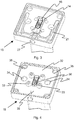
- a first connecting part 1 is shown with a female part 2 of a first embodiment of a connector.
- the first connecting part 1 has a bushing plate 3, which is provided centrally with a longitudinal opening 4, whereby the socket part 2 projects through and at the rear side of which the socket part 2 is fastened by means of non-apparent screws.
- On both sides and symmetrically to the socket part 2 four holes 5 are provided in a square, which are for receiving Allen screws (see FIG. 4 ) serve.
- two centering 6 are provided at a greater distance than the holes.
- the centering cams 6 are circular-cylindrical in the lower region 7 and conical in the upper region 8.
- the centering cams 6 are provided with an indentation 10 designed as an annular groove, which serves to receive a clip-shaped spring element (see FIG. 2 ) serves.
- the bushing plate 3 is screwed by means of Allen screws 11, for example, on a stand 13
- FIGS. 2 to 4 a second connecting part 15 are shown with a plug part 16 of the first embodiment of the connector.
- the second connecting part 15 has a plug plate 17, which has a central longitudinal opening 18 with widened, circularly rounded ends 19.
- this longitudinal opening 18 of the plug member 16 is embedded with its mounting plate 14 floating (see FIG. 3 ). Due to the floating attachment, the plug part 16 can exert a slight deflection in the longitudinal and in the transverse direction.
- the Plug plate 17 is further provided in the edge region of a U-shaped cutout 20, which serves to receive a clasp-shaped and U-shaped spring element 21.
- the spring element 21 is rod-shaped and has two straight legs 22 with free ends 23 and a slightly domed center part 24, which is located centrally in a transverse groove 25 of a slider 26 perpendicular thereto with an actuating means or push button 27.
- the slider 26 with the push button can be integrally formed.
- blind holes 28 are provided on both sides, which serve to receive the centering cam 6.
- On both sides of the central longitudinal opening 18 symmetrically four through holes 29 are mounted in the connector plate 17. At the four corner regions 30 of the connector plate 17 further four holes 31 are provided which serve to receive the Allen screws 11 of the first connection part 1.
- FIG. 4 is a cover plate 32 can be seen, which are screwed by means of Allen screws 33 in the through holes 29 of the connector plate 17.
- the cover plate 32 is screwed by means of Allen screws 33 in the through holes 29 of the connector plate 17.
- the bores 28 of the connector plate 17 are bores 34 and coincident with the bores 31 of the connector plate 17 angular recesses 35 are provided in the cover plate 32, so that the Allen screws 11 (see Fig. 1 ) can be recorded there.
- a longitudinal opening 36 is further inserted, which corresponds to the outer contour of the male part 16 with a small clearance.
- the mounting plate 14 of the male part 16 is held only by the longitudinal opening 18 of the connector plate 17 and the outer contour of the male part 16 of the longitudinal opening 36 of the adjoining cover plate 32 with a certain play without further attachment.
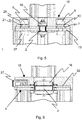
- FIGS. 5 and 6 Now show a cross section through the first connecting part 1 and the second connecting part 15 in the assembled state.
- the centering cams 6 are screwed on the back with a Allen screw 37 to the socket plate 3.
- the centering cam 6 serve for one-dimensional guidance in the connecting direction of the plug connection. So the first connection part 1 can be correctly mated with the second connection part 15, the socket part 4 and the plug part 16 have a trapezoidal outer contour.
- the centering cams 6 and the bores 30 are aligned slightly asymmetrically in the longitudinal direction of the socket part 4 and of the plug part 16.
- a character 38 in the form of a V provided on the socket plate 3 (see Fig. 1 ) and on the cover plate 32 (see Fig. 4 ) a character 38 in the form of a V provided.
- the clip-shaped spring element 21 is slightly pushed outwardly when inserted over the conical region 8 of the centering 6 and then engages in the formed as an annular groove 10 of the centering cams 6 a. It is understood that a simple indentation 10 may be provided, which is present only in the region of the latching of the spring element 21.
- the push button 27 is actuated, ie pressed inwards, as in FIG. 3 represented, whereby the two legs 22 are moved to the outside and thus the centering cams 6 are released.
- the second connecting part 15 can then be easily lifted from the first connecting part 1, so that at the same time the plug connection between the socket part 2 and the plug part 16 is released.
- the centering cam 6 with the annular groove 10 and the spring element 21 forms a releasable latching connection for the first connecting part 1 with the second connecting part 15th
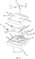
- a second embodiment of the connector is in the FIGS. 7 to 10 shown.
- a first connecting part 40 with a socket part 41 is made FIG. 7 seen.
- two centering cams 43 are fixed, which are formed with a longer circular cylindrical lower portion 44 and a conical upper portion 45. Between these two areas 44 and 45, a wide groove formed as an indentation 46 is provided.
- a second connecting part 48 is shown with a plug part 49 of the second embodiment in the assembled state.
- a rectangular cutout 51 is provided, which serves for the exception of a cuboid slide plate 52.
- the slide plate 52 is formed in the upper region with two lateral stops 56 for the coil springs 55 and with a lower cranked stop 57 for an actuating means or push button 58.
- the slide plate 52 also has centrally an upper opening 60 and a lower opening 61 which are aligned with the centering cams 43 and have a diameter of at least the diameter of the centering cams 43.
- the plug plate 50 is further provided with four holes (not shown) through which four Allen screws 62 inserted through and not visible in threaded holes) of a standpipe 75 are screwed.
- a trough-shaped cover plate 64 which has the holes 60 and 61 corresponding holes 65 and 66 is screwed with Allen screws 68 in threaded holes 69 of the connector plate 50.
- the second connecting part 48 can be plugged with the plug part 49 on the first connecting part 40 with the socket part 41.
- the socket part 41 and the plug part 49 are arranged at the edge.
- the centering cams 43 are also arranged slightly eccentrically on the axis perpendicular to the bushing part 41. The same applies to the openings 61 and 62 or the bores 65 and 66.
- the centering cam 43 and the slide plate 52 have the same function as in the first embodiment.
- FIGS. 11 to 16 Now various applications for the inventive connector with the first and second connecting part 1 and 15 or 40 and 48 are shown.
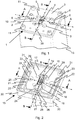
- FIG. 11 shows a ceiling light 70 with a four-edge mounting tube 71 to which the second connecting part 15 and 48 is attached.
- the first connection part 1 or 40 is attached to a ceiling (not shown).
- FIG. 12 the first connecting part 1 is shown with a cover 72 which is pushed over after the wall mounting of the first connecting part 1.
- the first connecting parts 1 are wired to the desired locations and fixed to the wall or ceiling and then protected with the covers 72, so that possible plasterer and painting work can be completed. Only in the final assembly of the lights with the second Connector 15 are then removed the covers 72.
- FIG. 13 is a table lamp 73 with the first connecting part 1, which is housed in a square tube 74, and the second connecting part 15, which is fastened to a four-edge standpipe 75 shown.
- a lamp body 76 is attached on the standpipe 75.
- the square tube 74 is mounted on a support plate 77 which can be mounted on a table top.
- the electrical leads are connected in the usual way via a cable channel with the first connecting part 1 (not shown).
- a floor lamp 80 is shown having the first connection part 1 housed in a square tube 81 and the second connection part 15 fixed to a four-edge standpipe 82.
- the square tube 81 has in one piece an H-shaped stand 83.
- the electrical supply line is formed here by a (not shown) electrical cable.
- FIG. 15 is a wall lamp 85 with the first connection part 1, which is fixed to a wall (not shown), and the second connection part 15, which is attached via a short square connecting pipe 86 with a lamp body 87, shown.
- FIG. 16 is a work table 90 with a worktop 91 and therein directly recessed first connecting parts 1 shown.
- the work lights 92 are then inserted as needed via the second connecting parts 15.
- Unused first connecting parts 1 can be protected by a cap (not shown)
- first connection part 1 or 40 and the second connection part 2 or 41 are made of chrome steel by laser beam and / or aluminum by milling.
- the centering cams 6 or 43 are also made of chrome steel.
- the electrical plug connection can also be formed by the two centering cams 6 or 45 and mating contacts, not shown, on the second connection part 15 or 48.
- the connector could be made via a single centering cam 6 or 45 with a coaxial connection. Since usually a transformer not shown here is present in the base 13, which provides a DC voltage of 24 V, such a connector is completely safe. In this case, the centering cams 6 or 45 must be fixed with an electrically insulating material opposite to the first connecting part 1 or 40.
Abstract
Description
- Die Erfindung betrifft eine Steckverbindung für einen Lampenkörper nach dem Oberbegriff des Patentanspruchs 1.
- Steckverbindungen für einen Lampenkörper sind allgemein bekannt, die ein erstes Verbindungsteil mit einem Steckerteil und ein zweites Verbindungsteil mit einem Buchsenteil aufweisen, wobei das erste Verbindungsteil mit dem zweiten Verbindungsteil mechanisch koppelbar und gleichzeitig der Steckerteil mit dem Buchsenteil elektrisch verbindbar ist.
- Beispielsweise ist aus
GB-A-1,043,936 - Aus
DE-A-36 25 66 ist ferner eine Steckverbindung mit einer Befestigungsplatte und einem Lampenkörper bekannt, bei welcher Ansätze des Lampenkörpers in Schlitze der Befestigungsplatte eingreifen. An der Befestigungsplatte ist ein Steckverbinder und am Lampenkörper ist eine Federleiste vorgesehen. Der Lampenkörper wird auf die Befestigungsplatte geschoben, so dass gleichzeitig eine mechanische und eine elektrische Verbindung zwischen der Befestigungsplatte und dem Lampenkörper entsteht. Es ist ferner eine Rastklinke an der Befestigungsplatte vorgesehen, welche in eine Rastausnehmung des Lampenkörpers eingreift. Des Weiteren durchgreift eine Sperrschraube eine der Ausnehmungen zwischen den Ansätzen der Befestigungsplatte, so dass der Lampenkörper ohne Werkzeug nicht von der Befestigungsplatte gelöst werden kann. - Ferner ist eine Montagevorrichtung für eine Leuchte aus
EP-A-0 777 079 bekannt, die ein an ener Wand oder Decke anbringbares Befestigungsteil und eine an diesem Befestigungsteil anbringbare Leuchtenarmatur aufweist. Die mechanische Verbindung von Befesttigungsteil und Leuchtenarmatur umfasst eine Zwangsführung durch Führungseinrichtungen des Befestigungsteils und Führungselemente der Leuchtenarmatur, wobei beim Verschieben der Leuchtenarmatur gegenüber dem Befestigungsteil gleichzeitig eine mechanische als auch eine elektrische Verbindung zwischen einem Steckerteil und einem Buchsenteil hergestellt wird. Nachdem die Leuchtenarmatur in das Befestigungsteil hineingeschoben ist, wird die Leuchtenarmatur mit einer Schraube in einer Gewindebohrung des Befestigungsteils fixiert. - Bei den obigen bekannten Steckverbindungen weisen alle zwei Führungen auf, welche senkrecht zu einander ausgerichtet sind: die zwei Teile müssen zunächst auf einander ausgerichtet und das Teil am Lampenkörper senkrecht zum anderen Teil gedrückt werden, bevor die beiden Teile waagerecht zusammengeschoben werden können. Deshalb braucht es beide Hände und einiges Geschick, um die beiden Teile richtig mechanisch und elektrisch zusammenzubringen.
- Der vorliegenden Erfindung liegt nun die Aufgabe zugrunde, eine Steckverbindung für einen Lampenkörper anzugeben, die eine sehr leichte Kopplung der beiden Teile ermöglicht und die Kopplung ohne Werkzeuge wieder gelöst werden kann.
- Diese Aufgabe wird durch eine Steckverbindung für einen Lampenkörper mit den Merkmalen des Patentanspruchs 1 gelöst.
- Die Erfindung hat den Vorteil, dass die Kopplung der Steckverbindung einhändig mit einer einzigen eindimensionalen Bewegung durchgeführt werden kann.
- Die erfindungsgemässe Steckverbindung für einen Lampenkörper weist ein erstes Verbindungsteil mit einem Buchsenteil und ein zweites Verbindungsteil mit einem Steckerteil auf, wobei das zweite Verbindungsteil mit dem ersten Verbindungsteil mechanisch koppelbar und gleichzeitig der Steckerteil mit dem Buchsenteil elektrisch verbindbar ist. Die Steckverbindung weist ferner ausschlieslich eine eindimensionale Führung in Verbindungsrichtung der Steckverbindung und eine manuell lösbare, senkrecht zur Verbindungsrichtung wirkende Rastverbindung auf.
- Vorteilhafterweise ist die Rastverbindung von mindestens einem vorstehenden Zentriernocken mit einer seitlichen Einbuchtung am ersten Verbindungsteil und von einer Bohrung und einem Federelement am zweiten Verbindungselement gebildet ist, derart dass bei der mechanischen Kopplung das Federelement in die Einbuchtung des Zentriernockens einrastet, wobei ein Betätigungsmittel am Federelement vorgesehen ist, um die Rastverbindung zu lösen.
- Ferner kann das Federelement als U-förmige Spange ausgebildet sein, welche in einer U-förmigen Ausfräsung im zweiten Verbindungsteil gehalten ist.
- Das Federelement ist von Vorteil mit einem leicht bombierten Mittelteil versehen, welcher mittig in einer Quernut eines senkrecht dazu stehenden Schiebers gehalten ist, wobei der Schieber mit dem Bestätigungsmittel verbunden ist.
- Dabei kann der Schieber mit dem Betätigungsmittel einstückig ausgebildet sein. Die Rastverbindung kann in einer Variante von mindestens einem vorstehenden Zentriernocken mit einer seitlichen Einbuchtung am ersten Verbindungsteil und von einer Schieberplatte mit einer zugeordneten Öffnung und einem Federelement am zweiten Verbindungsmittel ausgebildet sein, derart dass bei der mechanischen Kopplung die Schieberplatte in die Einbuchtung des Zentriernockens einrastet, wobei ein Betätigungsmittel an der Schieberplatte vorgesehen ist, um die Rastverbindung zu lösen.
- Dabei kann das Federelement der Variante von mindestens einer Spiralfeder gebildet sein, welche gegen einen Anschlag in einer Ausfräsung des zweiten Verbindungsteils drückt.
- Weitere Vorteile der Erfindung folgen aus den abhängigen Patentansprüchen und aus der nachfolgenden Beschreibung, in welcher die Erfindung anhand eines in den schematischen Zeichnungen dargestellten Ausführungsbeispieles näher erläutert wird. Es zeigt:
- Fig. 1
- ein erstes Verbindungsteil mit einem Buchsenteil einer ersten Ausführungsform in perspektivischer Darstellung,
- Fig. 2
- ein zweites Verbindungsteil mit einem Steckerteil und geschlossenem Rastelement der ersten Ausführungsform in perspektivischer Darstellung,
- Fig. 3
- das zweite Verbindungsteil der
Figur 2 mit geöffnetem Rastelement in perspektivischer Darstellung, - Fig. 4
- das zweite Verbindungsteil der
Fig. 2 mit einer Abdeckung, - Fig. 5
- ein Querschnitt durch die verbundenen und eingerasteten ersten und zweiten Verbindungsteile in geschlossenem Zustand längs der Linie A-A der
Figuren 1 und 2 , - Fig. 6
- einen Querschnitt durch die verbundenen und eingerasteten ersten und zweiten Verbindungsteile in geschlossenem Zustand längs der Linie B-B der
Figuren 1 und 2 , - Fig. 7
- ein erstes Verbindungsteil einer zweiten Ausführungsform der Steckverbindung in perspektivischer Darstellung,
- Fig. 8
- ein zweites Verbindungsteil der zweiten Ausführungsform in perspektivischer Darstellung,
- Fig. 9
- das zweite Verbindungsteil der zweiten Ausführungsform mit entfernter Abdeckung,
- Fig. 10
- eine Explosionsdarstellung des zweiten Verbindungsteils der zweiten Ausführungsform,
- Fig. 11
- eine Deckenleuchte mit der Steckverbindung in perspektivischer Darstellung,
- Fig. 12
- das erste Verbindungsteil der ersten Ausführungsform mit einer Abdeckkappe,
- Fig. 13
- eine Tischleuchte mit der Steckverbindung in perspektivischer Darstellung,
- Fig. 14
- eine Standleuchte mit der Steckverbindung in perspektivischer Darstellung,
- Fig. 15
- eine Wandleuchte mit der Steckverbindung in perspektivischer Darstellung, und
- Fig. 16
- einen Arbeitstisch mit einer Pultleuchte in abgehobenem Zustand und mit einer Pultleuchte in montiertem Zustand.
- In den Figuren sind für dieselben Elemente jeweils dieselben Bezugszeichen verwendet worden und erstmalige Erklärungen betreffen alle Figuren, wenn nicht ausdrücklich anders erwähnt.
- In der
Figur 1 ist ein erstes Verbindungsteil 1 mit einem Buchsenteil 2 einer ersten Ausführungsform einer Steckverbindung gezeigt. Das erste Verbindungsteil 1 weist eine Buchsenplatte 3 auf, welche mittig mit einer Längsöffnung 4 versehen ist, wodurch der Buchsenteil 2 hindurchragt und an deren Rückseite der Buchsenteil 2 mittels nicht-ersichtlichen Schrauben befestigt ist. Beidseitig und symmetrisch zum Buchsenteil 2 sind in einem Quadrat vier Bohrungen 5 vorgesehen, die zur Aufnahme von Inbusschrauben (sieheFigur 4 ) dienen. Ebenfalls symmetrisch zum Buchsenteil 2 sind auf einem grösseren Abstand als die Bohrungen 5 zwei Zentriernocken 6 vorgesehen. Die Zentriernocken 6 sind im unteren Bereich 7 kreiszylindrisch und im oberen Bereich 8 konisch ausgebildet. Im kreiszylindrischen Bereich 8 sind die Zentriernocken 6 mit einer als Ringnut ausgebildeten Einbuchtung 10 versehen, welche zur Aufnahme eines spangenförmigen Federelement (sieheFigur 2 ) dient. Die Buchsenplatte 3 ist mittels Inbusschrauben 11 beispielsweise auf einem Standfuss 13 festgeschraubt - In den
Figuren 2 bis 4 sind ein zweites Verbindungsteil 15 mit einem Steckerteil 16 der ersten Ausführungsform der Steckverbindung gezeigt. Das zweite Verbindungsteil 15 weist eine Steckerplatte 17 auf, welche eine mittige Längsöffnung 18 mit verbreiterten, kreisförmig abgerundeten Enden 19 aufweist. In dieser Längsöffnung 18 ist der Steckerteil 16 mit seiner Befestigungsplatte 14 schwimmend eingelassen (sieheFigur 3 ). Durch die schwimmende Befestigung kann der Steckerteil 16 eine leichte Auslenkung in longitudinale und in transversale Richtung ausüben. In der Steckerplatte 17 ist ferner im Randbereich eine U-förmige Ausfräsung 20 vorgesehen, welche zur Aufnahme eines spangenförmigen und U-förmigen Federelements 21 dient. Das Federelement 21 ist stabförmig und weist zwei gerade Beine 22 mit freien Enden 23 und einem leicht bombierten Mittelteil 24 auf, welcher mittig in einer Quernut 25 eines senkrecht dazu stehenden Schiebers 26 mit einem Betätigungsmittel oder Druckknopf 27 liegt. Der Schieber 26 mit dem Druckknopf kann dabei einstückig ausgebildet sein. Auf der Innenseite der U-förmige Ausfräsung 20 sind auf beiden Seiten Sackbohrungen 28 vorgesehen, die zur Aufnahme der Zentriernocken 6 dienen. Beidseitig der mittigen Längsöffnung 18 sind symmetrisch vier Durchgangsbohrungen 29 in der Steckerplatte 17 angebracht. An den vier Eckbereichen 30 der Steckerplatte 17 sind ferner vier Bohrungen 31 vorgesehen, die zur Aufnahme der Inbusschrauben 11 des ersten Verbindungsteils 1 dienen. - In
Figur 4 ist eine Abdeckplatte 32 ersichtlich, welche mittels Inbusschrauben 33 in die Durchgangsbohrungen 29 der Steckerplatte 17 eingeschraubt sind. Übereinstimmend mit den Bohrungen 28 der Steckerplatte 17 sind Bohrungen 34 und übereinstimmend mit den Bohrungen 31 der Steckerplatte 17 sind winkelförmige Ausnehmungen 35 in der Abdeckplatte 32 vorgesehen, so dass die Inbussschrauben 11 (sieheFig. 1 ) dort aufgenommen werden können. In der Abdeckplatte 32 ist ferner eine Längsöffnung 36 eingelassen, welche der Aussenkontur des Steckerteils 16 mit einem geringen Spiel entspricht. Somit ist die Befestigungsplatte 14 des Steckerteils 16 nur von der Längsöffnung 18 der Steckerplatte 17 und die Aussenkontur des Steckerteils 16 von der Längsöffnung 36 der anschliessenden Abdeckplatte 32 mit einem gewissen Spiel ohne weitere Befestigung festgehalten. - Die
Figuren 5 und 6 zeigen nun einen Querschnitt durch den ersten Verbindungsteil 1 und den zweiten Verbindungsteil 15 in zusammengesteckten Zustand. Wie ersichtlich sind die Zentriernocken 6 auf der Rückseite mit einer Inbusschraube 37 an die Buchsenplatte 3 festgeschraubt. Beim Zusammenstecken des ersten Verbindungsteils 1 mit dem zweiten Verbindungsteil 15 dienen die Zentriernocken 6 zur eindimensionalen Führung in Verbindungsrichtung der Steckverbindung. Damit der erste Verbindungteil 1 richtig mit dem zweiten Verbindungsteil 15 zusammengesteckt werden kann, weisen der Buchsenteil 4 und der Steckerteil 16 eine trapezförmige aussere Kontur auf. Ferner sind die Zentriernocken 6 und die Bohrungen 30 leicht assymetrisch in Längsrichtung des Buchsenteils 4 und des Steckerteils 16 ausgerichtet. Ebenfalls ist auf der Buchsenplatte 3 (sieheFig. 1 ) und auf der Abdeckplatte 32 (sieheFig. 4 ) ein Zeichen 38 in der Form eines V vorgesehen. - Das spangenförmige Federelement 21 wird beim Einstecken über den konischen Bereich 8 der Zentriernocken 6 leicht nach aussen gedrückt und rastet anschliessend in die als Ringnut ausgebildete Einbuchtung 10 der Zentriernocken 6 ein. Es versteht sich, dass auch eine einfache Einbuchtung 10 vorgesehen sein kann, die nur im Bereich der Einrastung des Federelements 21 vorhanden ist. Um diese Einrastung manuell zu lösen, wird der Druckknopf 27 betätigt, d.h. nach innen gedrückt, wie in
Figur 3 dargestellt, wodurch die beiden Beine 22 nach aussen bewegt werden und somit die Zentriernocken 6 freigegeben werden. Das zweite Verbindungsteil 15 kann dann einfach vom ersten Verbindungsteil 1 abgehoben werden, so dass gleichzeitig die Steckverbindung zwischen dem Buchsenteil 2 und dem Steckerteil 16 gelöst wird. Somit bildet der Zentriernocken 6 mit der Ringnut 10 und das Federelement 21 eine lösbare Rastverbindung für den ersten Verbindungsteil 1 mit dem zweiten Verbindungsteil 15. - Eine zweite Ausführungsform der Steckverbindung ist in den
Figuren 7 bis 10 dargestellt. Ein erstes Verbindungsteil 40 mit einem Buchsenteil 41 ist ausFigur 7 ersichtlich. Auf einer Buchsenplatte 42 sind zwei Zentriernocken 43 befestigt, welche mit einem längeren kreiszylindrischen unteren Bereich 44 und einem konischen oberen Bereich 45 ausgebildet sind. Zwischen diesen beiden Bereichen 44 und 45 ist eine breite als Ringnut ausgebildete Einbuchtung 46 vorgesehen. In denFiguren 8 bis 10 ist ein zweiter Verbindungsteil 48 mit einem Steckerteil 49 der zweiten Ausführungsform in zusammengebauten Zustand gezeigt. Auf einer Steckerplatte 50 ist eine quaderförmige Ausfräsung 51 vorgesehen, die zur Ausnahme einer quaderförmigen Schieberplatte 52 dient. Wie aus denFiguren 9 und10 ersichtlich sind im oberen Bereich 53 der Ausfräsung 51 längliche Ausbuchtungen 54 vorgesehen, die als Widerlager und Aufnahme von zwei Spiralfedern 55 dienen. Die Schieberplatte 52 ist im oberen Bereich mit zwei seitlichen Anschlägen 56 für die Spiralfedern 55 und mit einem unteren gekröpften Anschlag 57 für ein Betätigungsmittel oder Druckknopf 58 ausgebildet. Die Schieberplatte 52 weist ferner mittig eine obere Öffnung 60 und eine untere Öffnung 61 auf, welche zu den Zentriernocken 43 ausgerichtet sind und einen Durchmesser von mindestens dem Durchmesser der Zentriernocken 43 aufweisen. Die Steckerplatte 50 ist ferner mit vier Bohrungen (nicht ersichtlich) versehen, durch welche vier Inbusschrauben 62 hindurch gesteckt und in Gewindebohrungen nicht ersichtlich) eines Standrohres 75 hineingeschraubt sind. Um die Inbusschrauben 62 im halbmontierten zweiten Verbindungsteil 48 auf das Standrohr 75 festzuschrauben, sind entsprechende Bohrungen 63 in der Schieberplatte 52 vorgesehen (sieheFigur 9 ). Eine wannenförmige Abdeckplatte 64, welche den Öffnungen 60 und 61 entsprechende Bohrungen 65 und 66 aufweist, ist mit Inbusschrauben 68 in Gewindebohrungen 69 der Steckerplatte 50 festgeschraubt. - Wie nun aus den
Figuren 7 und 8 erkennbar, kann der zweite Verbindungsteil 48 mit dem Steckerteil 49 auf den ersten Verbindungsteil 40 mit dem Buchsenteil 41 aufgesteckt werden. Damit diese Teile 48 und 40 richtig zusammengesteckt werden, sind der Buchsenteil 41 und der Steckerteil 49 am Rand angeordnet. Andererseits sind auch die Zentriernocken 43 auf der Achse senkrecht zum Buchsenteil 41 leicht exzentrisch angeordnet. Das gleiche gilt für die Öffnungen 61 und 62 bzw. die Bohrungen 65 und 66. Die Zentriernocken 43 und die Schieberplatte 52 haben dieselbe Funktion wie bei der ersten Ausführungsform. - In den
Figuren 11 bis 16 sind nun verschiedene Anwendungen für die erfindungsgemässe Steckverbindung mit dem ersten und zweiten Verbindungsteil 1 und 15 bzw. 40 und 48 gezeigt. -
Figur 11 zeigt eine Deckenleuchte 70 mit einem vierkanten Befestigungsrohr 71, an welchem das zweite Verbindungsteil 15 bzw. 48 befestigt ist. Das erste Verbindungsteil 1 bzw. 40 ist dabei an einer Decke befestigt (nicht dargestellt). - In
Figur 12 ist das erste Verbindungsteil 1 mit einer Abdeckung 72 gezeigt, welche nach der Wandmontage des ersten Verbindungsteils 1 darüber geschoben wird. Bei der Ausstattung eines Büroraumes werden die ersten Verbindungsteile 1 an den gewünschten Orten verkabelt und an der Wand oder Decke befestigt und sodann mit den Abdeckungen 72 geschützt, damit mögliche Gipser- und Malerarbeiten fertig gestellt werden können.Erst bei der Endmontage der Leuchten mit dem zweiten Verbindungsteil 15 werden sodann die Abdeckungen 72 entfernt. - In
Figur 13 ist eine Tischleuchte 73 mit dem ersten Verbindungsteil 1, der in einem Vierkantrohr 74 untergebracht ist, und dem zweiten Verbindungsteil 15, der an einem vierkanten Standrohr 75 besfestigt ist, gezeigt. Am Standrohr 75 ist ein Lampenkörper 76 befestigt. Das Vierkantrohr 74 ist auf einer Tragplatte 77 befestigt, welche auf einer Tischplatte befestigt werden kann. Die elektrischen Zuleitungen werden in üblicher Art über einen Kabelkanal mit dem ersten Verbindungsteil 1 verbunden (nicht weiter dargestellt). - In
Figur 14 ist eine Stehleuchte 80 mit dem ersten Verbindungsteil 1, der in einem Vierkantrohr 81 untergebracht ist, und dem zweiten Verbindungsteil 15, der an einem vierkanten Standrohr 82 befestigt ist, gezeigt. Das Vierkantrohr 81 weist einstückig einen H-förmigen Standfuss 83 auf. Die elektrische Zuleitung wird hier von einem (nicht dargestellten) elektrischen Kabel gebildet. - In
Figur 15 ist eine Wandleuchte 85 mit dem ersten Verbindungsteil 1, der an einer Wand befestigt ist (nicht dargestellt), und dem zweiten Verbindungsteil 15, der über einem kurzen vierkanten Anschlussrohr 86 mit einem Lampenkörper 87 befestigt ist, gezeigt. - In
Figur 16 ist ein Arbeitstisch 90 mit einer Arbeitsplatte 91 und darin direkt eingelassenen ersten Verbindungsteilen 1 gezeigt. Die Arbeitsleuchten 92 werden sodann je nach Bedarf über die zweiten Verbindungsteilen 15 eingesteckt. Nichtbenutzte erste Verbindungsteile 1 können mit einer (nicht dargestellten) Abdeckkappe geschützt werde - In den obengeannten Ausführungen sind das erste Verbindungsteil 1 oder 40 und das zweite Verbindungsteil 2 oder 41 aus Chromstahl mittels Laserstrahl und/oder aus Aluminium durch Fräsen hergestellt. Auch die Zentriernocken 6 oder 43 sind aus Chromstahl gedreht.
- Anstelle einer Steckverbindung mit einem Buchsenteil 2 oder 41 und einem Steckerteil 16 oder 49 kann die elektrische Steckverbindung auch von den beiden Zentriernocken 6 oder 45 und nicht dargestellten Gegenkontakten auf dem zweiten Verbindungsteil 15 oder 48 gebildet werden. Auch könnte die Steckverbindung über einen einzelnen Zentriernocken 6 oder 45 mit einer Koaxial-Verbindung hergestellt werden. Da üblicherweise ein hier nicht dargestellter Transformator im Standfuss 13 vorhanden ist, welche eine Gleichspannung von 24 V liefert, ist ein solche Steckverbindung vollkommen ungefährlich. In diesem Fall müssen die Zentriernocken 6 oder 45 mit einer elektrisch isolierenden Material gegenüber dem ersten Verbindungsteil 1 oder 40 befestigt werden.
Claims (7)
- Steckverbindung für einen Lampenkörper, welche ein erstes Verbindungsteil (1; 40) mit einem Buchsenteil (2; 41) und ein zweites Verbindungsteil (15; 48) mit einem Steckerteil (16; 49) aufweist, wobei das zweite Verbindungsteil mit dem ersten Verbindungsteil mechanisch koppelbar und gleichzeitig der Steckerteil mit dem Buchsenteil elektrisch verbindbar ist, dadurch gekennzeichnet, dass die Steckverbindung ausschlieslich eine eindimensionale Führung in Verbindungsrichtung der Steckverbindung und eine manuell lösbare, senkrecht zur Verbindungsrichtung wirkende Rastverbindung aufweist.
- Steckverbindung nach Anspruch 1, dadurch gekennzeichnet, dass die Rastverbindung von mindestens einem vorstehenden Zentriernocken (6) mit einer seitlichen Einbuchtung (10) am ersten Verbindungsteil (1) und von einer Bohrung (28) und einem Federelement (21) am zweiten Verbindungselement (15) gebildet ist, derart dass bei der mechanischen Kopplung das Federelement (21) in die Einbuchtung des Zentriernockens (6) einrastet, wobei ein Betätigungsmittel (27) am Federelement (21) vorgesehen ist, um die Rastverbindung zu lösen.
- Steckverbindung nach Anspruch 2, dadurch gekennzeichnet, dass das Federelement als U-förmige Spange (21) gebildet ist, welche in einer U-förmigen Ausfräsung (20) im zweiten Verbindungsteil (15) gehalten ist.
- Steckverbindung nach Anspruch 3, dadurch gekennzeichnet, dass das Federelement mit einem leicht bombierten Mittelteil (24) versehen ist, welcher mittig in einer Quernut (25) eines senkrecht dazu stehenden Schiebers (26) gehalten ist, wobei der Schieber (26) mit dem Bestätigungsmittel (27) verbunden ist.
- Steckverbindung nach Anspruch 4, dadurch gekennzeichnet, dass der Schieber (26) mit dem Betätigungsmittel (27) einstückig ausgebildet ist.
- Steckverbindung nach Anspruch 2, dadurch gekennzeichnet, dass die Rastverbindung von mindestens einem vorstehenden Zentriernocken (43) mit einer seitlichen Einbuchtung (46) am ersten Verbindungsteil (40) und von einer Schieberplatte (52) mit einer zugeordneten Öffnung (60, 61) und einem Federelement (55) am zweiten Verbindungsmittel (48) gebildet ist, derart dass bei der mechanischen Kopplung die Schieberplatte (52) in die Einbuchtung des Zentriernockens (43) einrastet, wobei ein Betätigungsmittel (27) an der Schieberplatte (52) vorgesehen ist, um die Rastverbindung zu lösen.
- Steckverbindung nach Anspruch 6, dadurch gekennzeichnet, dass das Federelement von mindestens einer Spiralfeder (55) gebildet ist, welche gegen einen Anschlag (56) in einer Ausfräsung (51) des zweiten Verbindungsteils (48) drückt.
Applications Claiming Priority (1)
| Application Number | Priority Date | Filing Date | Title |
|---|---|---|---|
| CH01026/16A CH712795A2 (de) | 2016-08-10 | 2016-08-10 | Steckverbindung für einen Lampenkörper. |
Publications (2)
| Publication Number | Publication Date |
|---|---|
| EP3282178A1 true EP3282178A1 (de) | 2018-02-14 |
| EP3282178B1 EP3282178B1 (de) | 2020-04-29 |
Family
ID=59569224
Family Applications (1)
| Application Number | Title | Priority Date | Filing Date |
|---|---|---|---|
| EP17185403.7A Active EP3282178B1 (de) | 2016-08-10 | 2017-08-08 | Steckverbindung für einen lampenkörper |
Country Status (2)
| Country | Link |
|---|---|
| EP (1) | EP3282178B1 (de) |
| CH (1) | CH712795A2 (de) |
Families Citing this family (1)
| Publication number | Priority date | Publication date | Assignee | Title |
|---|---|---|---|---|
| USD953594S1 (en) * | 2021-01-20 | 2022-05-31 | Chuanqi Fu | Lamp |
Citations (3)
| Publication number | Priority date | Publication date | Assignee | Title |
|---|---|---|---|---|
| US6074235A (en) * | 1998-04-07 | 2000-06-13 | The Whitaker Corporation | Alignment post having an improved locking feature |
| US20060274519A1 (en) * | 2005-06-02 | 2006-12-07 | Pearce Richard A | Ceiling fan hanging system |
| EP2642613A2 (de) * | 2012-03-20 | 2013-09-25 | Siteco Beleuchtungstechnik GmbH | Leuchtenmontagesystem |
-
2016
- 2016-08-10 CH CH01026/16A patent/CH712795A2/de not_active Application Discontinuation
-
2017
- 2017-08-08 EP EP17185403.7A patent/EP3282178B1/de active Active
Patent Citations (3)
| Publication number | Priority date | Publication date | Assignee | Title |
|---|---|---|---|---|
| US6074235A (en) * | 1998-04-07 | 2000-06-13 | The Whitaker Corporation | Alignment post having an improved locking feature |
| US20060274519A1 (en) * | 2005-06-02 | 2006-12-07 | Pearce Richard A | Ceiling fan hanging system |
| EP2642613A2 (de) * | 2012-03-20 | 2013-09-25 | Siteco Beleuchtungstechnik GmbH | Leuchtenmontagesystem |
Also Published As
| Publication number | Publication date |
|---|---|
| CH712795A2 (de) | 2018-02-15 |
| EP3282178B1 (de) | 2020-04-29 |
Similar Documents
| Publication | Publication Date | Title |
|---|---|---|
| EP3345256B1 (de) | Halterahmen für steckverbindermodule mit einem fixierbaren rastbügel | |
| DE10002947C1 (de) | Verriegelungseinrichtung zum Verriegeln eines elektronischen Geräts an einem Kabel | |
| WO2015132177A1 (de) | Leuchte bzw. beleuchtungsanordnung mit länglichem trägerelement und lösbar befestigbarem leuchtmodul | |
| DE10035996B4 (de) | Näherungsschalter | |
| EP3282178B1 (de) | Steckverbindung für einen lampenkörper | |
| EP1132676A2 (de) | Vorrichtung zur Montage und zum elektrischen Anschluss von Leuchten | |
| DE102019109676A1 (de) | Haltefeder für Leuchte | |
| EP0999409B1 (de) | Deckeneinbauleuchte mit einer Leuchtenwanne und schwenkbaren Abstützarmen | |
| DE10013086A1 (de) | Einbauleuchte mit einem domförmigen Reflektor | |
| DE112015005935B4 (de) | Endkappe für eine Beleuchtungsvorrichtung und Beleuchtungsvorrichtung umfassend eine solche | |
| EP1586816A2 (de) | Deckenleuchte | |
| EP1193806B1 (de) | Steckverbindungseinrichtung, vorzugsweise für Aussenrückblickspiegel von Kraftfahrzeugen | |
| EP3522303B1 (de) | Anschlussblock | |
| DE10104757B4 (de) | Befestigungsvorrichtung zur verstellbaren Befestigung eines Fahrzeugteils | |
| WO2015193190A1 (de) | Beleuchtungsanordnung | |
| DE19854440A1 (de) | Verlängerungsstück für Leuchtstofflampen | |
| EP3086031B1 (de) | Leuchte zur befestigung in einer halterung, insbesondere in einer schienenhalterung | |
| DE102019130176B4 (de) | Steckverbinderteil mit einer Rasteinrichtung | |
| DE2717354C3 (de) | Verriegelung für Gehäuseteile eines elektrischen Installationsgerätes | |
| DE8424990U1 (de) | Näherungsschalter | |
| EP0733746A2 (de) | Halter | |
| EP0777079A1 (de) | Montagevorrichtung für eine Leuchte | |
| EP1351559B1 (de) | Befestigungssystem für elektrische und/oder mechanische Bauteile einer Leuchte | |
| DE7618061U1 (de) | Verbindungsstueck zum loesbaren verbinden von wenigstens zwei elementen eines beleuchtungskoerpers | |
| EP1463609B1 (de) | Bodenreinigungsgerät |
Legal Events
| Date | Code | Title | Description |
|---|---|---|---|
| PUAI | Public reference made under article 153(3) epc to a published international application that has entered the european phase |
Free format text: ORIGINAL CODE: 0009012 |
|
| STAA | Information on the status of an ep patent application or granted ep patent |
Free format text: STATUS: THE APPLICATION HAS BEEN PUBLISHED |
|
| AK | Designated contracting states |
Kind code of ref document: A1 Designated state(s): AL AT BE BG CH CY CZ DE DK EE ES FI FR GB GR HR HU IE IS IT LI LT LU LV MC MK MT NL NO PL PT RO RS SE SI SK SM TR |
|
| AX | Request for extension of the european patent |
Extension state: BA ME |
|
| STAA | Information on the status of an ep patent application or granted ep patent |
Free format text: STATUS: REQUEST FOR EXAMINATION WAS MADE |
|
| 17P | Request for examination filed |
Effective date: 20180814 |
|
| RBV | Designated contracting states (corrected) |
Designated state(s): AL AT BE BG CH CY CZ DE DK EE ES FI FR GB GR HR HU IE IS IT LI LT LU LV MC MK MT NL NO PL PT RO RS SE SI SK SM TR |
|
| STAA | Information on the status of an ep patent application or granted ep patent |
Free format text: STATUS: EXAMINATION IS IN PROGRESS |
|
| 17Q | First examination report despatched |
Effective date: 20181016 |
|
| GRAP | Despatch of communication of intention to grant a patent |
Free format text: ORIGINAL CODE: EPIDOSNIGR1 |
|
| STAA | Information on the status of an ep patent application or granted ep patent |
Free format text: STATUS: GRANT OF PATENT IS INTENDED |
|
| INTG | Intention to grant announced |
Effective date: 20191126 |
|
| GRAS | Grant fee paid |
Free format text: ORIGINAL CODE: EPIDOSNIGR3 |
|
| GRAA | (expected) grant |
Free format text: ORIGINAL CODE: 0009210 |
|
| STAA | Information on the status of an ep patent application or granted ep patent |
Free format text: STATUS: THE PATENT HAS BEEN GRANTED |
|
| AK | Designated contracting states |
Kind code of ref document: B1 Designated state(s): AL AT BE BG CH CY CZ DE DK EE ES FI FR GB GR HR HU IE IS IT LI LT LU LV MC MK MT NL NO PL PT RO RS SE SI SK SM TR |
|
| REG | Reference to a national code |
Ref country code: GB Ref legal event code: FG4D Free format text: NOT ENGLISH |
|
| REG | Reference to a national code |
Ref country code: CH Ref legal event code: EP |
|
| REG | Reference to a national code |
Ref country code: DE Ref legal event code: R096 Ref document number: 502017004950 Country of ref document: DE |
|
| REG | Reference to a national code |
Ref country code: AT Ref legal event code: REF Ref document number: 1263862 Country of ref document: AT Kind code of ref document: T Effective date: 20200515 |
|
| REG | Reference to a national code |
Ref country code: IE Ref legal event code: FG4D Free format text: LANGUAGE OF EP DOCUMENT: GERMAN |
|
| REG | Reference to a national code |
Ref country code: CH Ref legal event code: NV Representative=s name: SPIERENBURG AND PARTNER AG, PATENT- UND MARKEN, CH |
|
| REG | Reference to a national code |
Ref country code: NL Ref legal event code: MP Effective date: 20200429 |
|
| REG | Reference to a national code |
Ref country code: LT Ref legal event code: MG4D |
|
| PG25 | Lapsed in a contracting state [announced via postgrant information from national office to epo] |
Ref country code: NO Free format text: LAPSE BECAUSE OF FAILURE TO SUBMIT A TRANSLATION OF THE DESCRIPTION OR TO PAY THE FEE WITHIN THE PRESCRIBED TIME-LIMIT Effective date: 20200729 Ref country code: IS Free format text: LAPSE BECAUSE OF FAILURE TO SUBMIT A TRANSLATION OF THE DESCRIPTION OR TO PAY THE FEE WITHIN THE PRESCRIBED TIME-LIMIT Effective date: 20200829 Ref country code: PT Free format text: LAPSE BECAUSE OF FAILURE TO SUBMIT A TRANSLATION OF THE DESCRIPTION OR TO PAY THE FEE WITHIN THE PRESCRIBED TIME-LIMIT Effective date: 20200831 Ref country code: LT Free format text: LAPSE BECAUSE OF FAILURE TO SUBMIT A TRANSLATION OF THE DESCRIPTION OR TO PAY THE FEE WITHIN THE PRESCRIBED TIME-LIMIT Effective date: 20200429 Ref country code: SE Free format text: LAPSE BECAUSE OF FAILURE TO SUBMIT A TRANSLATION OF THE DESCRIPTION OR TO PAY THE FEE WITHIN THE PRESCRIBED TIME-LIMIT Effective date: 20200429 Ref country code: GR Free format text: LAPSE BECAUSE OF FAILURE TO SUBMIT A TRANSLATION OF THE DESCRIPTION OR TO PAY THE FEE WITHIN THE PRESCRIBED TIME-LIMIT Effective date: 20200730 Ref country code: FI Free format text: LAPSE BECAUSE OF FAILURE TO SUBMIT A TRANSLATION OF THE DESCRIPTION OR TO PAY THE FEE WITHIN THE PRESCRIBED TIME-LIMIT Effective date: 20200429 |
|
| PG25 | Lapsed in a contracting state [announced via postgrant information from national office to epo] |
Ref country code: HR Free format text: LAPSE BECAUSE OF FAILURE TO SUBMIT A TRANSLATION OF THE DESCRIPTION OR TO PAY THE FEE WITHIN THE PRESCRIBED TIME-LIMIT Effective date: 20200429 Ref country code: LV Free format text: LAPSE BECAUSE OF FAILURE TO SUBMIT A TRANSLATION OF THE DESCRIPTION OR TO PAY THE FEE WITHIN THE PRESCRIBED TIME-LIMIT Effective date: 20200429 Ref country code: RS Free format text: LAPSE BECAUSE OF FAILURE TO SUBMIT A TRANSLATION OF THE DESCRIPTION OR TO PAY THE FEE WITHIN THE PRESCRIBED TIME-LIMIT Effective date: 20200429 Ref country code: BG Free format text: LAPSE BECAUSE OF FAILURE TO SUBMIT A TRANSLATION OF THE DESCRIPTION OR TO PAY THE FEE WITHIN THE PRESCRIBED TIME-LIMIT Effective date: 20200729 |
|
| PG25 | Lapsed in a contracting state [announced via postgrant information from national office to epo] |
Ref country code: AL Free format text: LAPSE BECAUSE OF FAILURE TO SUBMIT A TRANSLATION OF THE DESCRIPTION OR TO PAY THE FEE WITHIN THE PRESCRIBED TIME-LIMIT Effective date: 20200429 Ref country code: NL Free format text: LAPSE BECAUSE OF FAILURE TO SUBMIT A TRANSLATION OF THE DESCRIPTION OR TO PAY THE FEE WITHIN THE PRESCRIBED TIME-LIMIT Effective date: 20200429 |
|
| PG25 | Lapsed in a contracting state [announced via postgrant information from national office to epo] |
Ref country code: ES Free format text: LAPSE BECAUSE OF FAILURE TO SUBMIT A TRANSLATION OF THE DESCRIPTION OR TO PAY THE FEE WITHIN THE PRESCRIBED TIME-LIMIT Effective date: 20200429 Ref country code: CZ Free format text: LAPSE BECAUSE OF FAILURE TO SUBMIT A TRANSLATION OF THE DESCRIPTION OR TO PAY THE FEE WITHIN THE PRESCRIBED TIME-LIMIT Effective date: 20200429 Ref country code: RO Free format text: LAPSE BECAUSE OF FAILURE TO SUBMIT A TRANSLATION OF THE DESCRIPTION OR TO PAY THE FEE WITHIN THE PRESCRIBED TIME-LIMIT Effective date: 20200429 Ref country code: SM Free format text: LAPSE BECAUSE OF FAILURE TO SUBMIT A TRANSLATION OF THE DESCRIPTION OR TO PAY THE FEE WITHIN THE PRESCRIBED TIME-LIMIT Effective date: 20200429 Ref country code: EE Free format text: LAPSE BECAUSE OF FAILURE TO SUBMIT A TRANSLATION OF THE DESCRIPTION OR TO PAY THE FEE WITHIN THE PRESCRIBED TIME-LIMIT Effective date: 20200429 Ref country code: DK Free format text: LAPSE BECAUSE OF FAILURE TO SUBMIT A TRANSLATION OF THE DESCRIPTION OR TO PAY THE FEE WITHIN THE PRESCRIBED TIME-LIMIT Effective date: 20200429 Ref country code: IT Free format text: LAPSE BECAUSE OF FAILURE TO SUBMIT A TRANSLATION OF THE DESCRIPTION OR TO PAY THE FEE WITHIN THE PRESCRIBED TIME-LIMIT Effective date: 20200429 |
|
| REG | Reference to a national code |
Ref country code: DE Ref legal event code: R097 Ref document number: 502017004950 Country of ref document: DE |
|
| PG25 | Lapsed in a contracting state [announced via postgrant information from national office to epo] |
Ref country code: SK Free format text: LAPSE BECAUSE OF FAILURE TO SUBMIT A TRANSLATION OF THE DESCRIPTION OR TO PAY THE FEE WITHIN THE PRESCRIBED TIME-LIMIT Effective date: 20200429 Ref country code: PL Free format text: LAPSE BECAUSE OF FAILURE TO SUBMIT A TRANSLATION OF THE DESCRIPTION OR TO PAY THE FEE WITHIN THE PRESCRIBED TIME-LIMIT Effective date: 20200429 |
|
| PLBE | No opposition filed within time limit |
Free format text: ORIGINAL CODE: 0009261 |
|
| STAA | Information on the status of an ep patent application or granted ep patent |
Free format text: STATUS: NO OPPOSITION FILED WITHIN TIME LIMIT |
|
| PG25 | Lapsed in a contracting state [announced via postgrant information from national office to epo] |
Ref country code: MC Free format text: LAPSE BECAUSE OF FAILURE TO SUBMIT A TRANSLATION OF THE DESCRIPTION OR TO PAY THE FEE WITHIN THE PRESCRIBED TIME-LIMIT Effective date: 20200429 |
|
| 26N | No opposition filed |
Effective date: 20210201 |
|
| PG25 | Lapsed in a contracting state [announced via postgrant information from national office to epo] |
Ref country code: LU Free format text: LAPSE BECAUSE OF NON-PAYMENT OF DUE FEES Effective date: 20200808 |
|
| REG | Reference to a national code |
Ref country code: BE Ref legal event code: MM Effective date: 20200831 |
|
| PG25 | Lapsed in a contracting state [announced via postgrant information from national office to epo] |
Ref country code: SI Free format text: LAPSE BECAUSE OF FAILURE TO SUBMIT A TRANSLATION OF THE DESCRIPTION OR TO PAY THE FEE WITHIN THE PRESCRIBED TIME-LIMIT Effective date: 20200429 |
|
| PG25 | Lapsed in a contracting state [announced via postgrant information from national office to epo] |
Ref country code: IE Free format text: LAPSE BECAUSE OF NON-PAYMENT OF DUE FEES Effective date: 20200808 Ref country code: BE Free format text: LAPSE BECAUSE OF NON-PAYMENT OF DUE FEES Effective date: 20200831 |
|
| PG25 | Lapsed in a contracting state [announced via postgrant information from national office to epo] |
Ref country code: TR Free format text: LAPSE BECAUSE OF FAILURE TO SUBMIT A TRANSLATION OF THE DESCRIPTION OR TO PAY THE FEE WITHIN THE PRESCRIBED TIME-LIMIT Effective date: 20200429 Ref country code: MT Free format text: LAPSE BECAUSE OF FAILURE TO SUBMIT A TRANSLATION OF THE DESCRIPTION OR TO PAY THE FEE WITHIN THE PRESCRIBED TIME-LIMIT Effective date: 20200429 Ref country code: CY Free format text: LAPSE BECAUSE OF FAILURE TO SUBMIT A TRANSLATION OF THE DESCRIPTION OR TO PAY THE FEE WITHIN THE PRESCRIBED TIME-LIMIT Effective date: 20200429 |
|
| PG25 | Lapsed in a contracting state [announced via postgrant information from national office to epo] |
Ref country code: MK Free format text: LAPSE BECAUSE OF FAILURE TO SUBMIT A TRANSLATION OF THE DESCRIPTION OR TO PAY THE FEE WITHIN THE PRESCRIBED TIME-LIMIT Effective date: 20200429 |
|
| PGFP | Annual fee paid to national office [announced via postgrant information from national office to epo] |
Ref country code: GB Payment date: 20230824 Year of fee payment: 7 Ref country code: CH Payment date: 20230902 Year of fee payment: 7 Ref country code: AT Payment date: 20230818 Year of fee payment: 7 |
|
| PGFP | Annual fee paid to national office [announced via postgrant information from national office to epo] |
Ref country code: FR Payment date: 20230822 Year of fee payment: 7 Ref country code: DE Payment date: 20230822 Year of fee payment: 7 |