EP3282178A1 - Connecteur pour un corps de la lampe - Google Patents
Connecteur pour un corps de la lampe Download PDFInfo
- Publication number
- EP3282178A1 EP3282178A1 EP17185403.7A EP17185403A EP3282178A1 EP 3282178 A1 EP3282178 A1 EP 3282178A1 EP 17185403 A EP17185403 A EP 17185403A EP 3282178 A1 EP3282178 A1 EP 3282178A1
- Authority
- EP
- European Patent Office
- Prior art keywords
- connecting part
- plug
- spring element
- connection
- connector
- Prior art date
- Legal status (The legal status is an assumption and is not a legal conclusion. Google has not performed a legal analysis and makes no representation as to the accuracy of the status listed.)
- Granted
Links
- 230000008878 coupling Effects 0.000 claims description 7
- 238000010168 coupling process Methods 0.000 claims description 7
- 238000005859 coupling reaction Methods 0.000 claims description 7
- 238000007373 indentation Methods 0.000 claims description 7
- 238000012790 confirmation Methods 0.000 claims description 2
- 229910000669 Chrome steel Inorganic materials 0.000 description 2
- 230000013011 mating Effects 0.000 description 2
- XAGFODPZIPBFFR-UHFFFAOYSA-N aluminium Chemical compound [Al] XAGFODPZIPBFFR-UHFFFAOYSA-N 0.000 description 1
- 229910052782 aluminium Inorganic materials 0.000 description 1
- 230000001419 dependent effect Effects 0.000 description 1
- 239000012777 electrically insulating material Substances 0.000 description 1
- 238000003801 milling Methods 0.000 description 1
- 238000010422 painting Methods 0.000 description 1
Images


Classifications
-
- F—MECHANICAL ENGINEERING; LIGHTING; HEATING; WEAPONS; BLASTING
- F21—LIGHTING
- F21V—FUNCTIONAL FEATURES OR DETAILS OF LIGHTING DEVICES OR SYSTEMS THEREOF; STRUCTURAL COMBINATIONS OF LIGHTING DEVICES WITH OTHER ARTICLES, NOT OTHERWISE PROVIDED FOR
- F21V21/00—Supporting, suspending, or attaching arrangements for lighting devices; Hand grips
- F21V21/002—Supporting, suspending, or attaching arrangements for lighting devices; Hand grips making direct electrical contact, e.g. by piercing
-
- F—MECHANICAL ENGINEERING; LIGHTING; HEATING; WEAPONS; BLASTING
- F21—LIGHTING
- F21V—FUNCTIONAL FEATURES OR DETAILS OF LIGHTING DEVICES OR SYSTEMS THEREOF; STRUCTURAL COMBINATIONS OF LIGHTING DEVICES WITH OTHER ARTICLES, NOT OTHERWISE PROVIDED FOR
- F21V21/00—Supporting, suspending, or attaching arrangements for lighting devices; Hand grips
- F21V21/08—Devices for easy attachment to any desired place, e.g. clip, clamp, magnet
-
- F—MECHANICAL ENGINEERING; LIGHTING; HEATING; WEAPONS; BLASTING
- F21—LIGHTING
- F21S—NON-PORTABLE LIGHTING DEVICES; SYSTEMS THEREOF; VEHICLE LIGHTING DEVICES SPECIALLY ADAPTED FOR VEHICLE EXTERIORS
- F21S8/00—Lighting devices intended for fixed installation
- F21S8/08—Lighting devices intended for fixed installation with a standard
- F21S8/081—Lighting devices intended for fixed installation with a standard of low-built type, e.g. landscape light
-
- H—ELECTRICITY
- H01—ELECTRIC ELEMENTS
- H01R—ELECTRICALLY-CONDUCTIVE CONNECTIONS; STRUCTURAL ASSOCIATIONS OF A PLURALITY OF MUTUALLY-INSULATED ELECTRICAL CONNECTING ELEMENTS; COUPLING DEVICES; CURRENT COLLECTORS
- H01R33/00—Coupling devices specially adapted for supporting apparatus and having one part acting as a holder providing support and electrical connection via a counterpart which is structurally associated with the apparatus, e.g. lamp holders; Separate parts thereof
- H01R33/74—Devices having four or more poles, e.g. holders for compact fluorescent lamps
- H01R33/76—Holders with sockets, clips, or analogous contacts adapted for axially-sliding engagement with parallely-arranged pins, blades, or analogous contacts on counterpart, e.g. electronic tube socket
- H01R33/765—Holders with sockets, clips, or analogous contacts adapted for axially-sliding engagement with parallely-arranged pins, blades, or analogous contacts on counterpart, e.g. electronic tube socket the terminal pins having a non-circular disposition
-
- H—ELECTRICITY
- H01—ELECTRIC ELEMENTS
- H01R—ELECTRICALLY-CONDUCTIVE CONNECTIONS; STRUCTURAL ASSOCIATIONS OF A PLURALITY OF MUTUALLY-INSULATED ELECTRICAL CONNECTING ELEMENTS; COUPLING DEVICES; CURRENT COLLECTORS
- H01R33/00—Coupling devices specially adapted for supporting apparatus and having one part acting as a holder providing support and electrical connection via a counterpart which is structurally associated with the apparatus, e.g. lamp holders; Separate parts thereof
- H01R33/74—Devices having four or more poles, e.g. holders for compact fluorescent lamps
- H01R33/76—Holders with sockets, clips, or analogous contacts adapted for axially-sliding engagement with parallely-arranged pins, blades, or analogous contacts on counterpart, e.g. electronic tube socket
- H01R33/7664—Holders with sockets, clips, or analogous contacts adapted for axially-sliding engagement with parallely-arranged pins, blades, or analogous contacts on counterpart, e.g. electronic tube socket having additional guiding, adapting, shielding, anti-vibration or mounting means
-
- F—MECHANICAL ENGINEERING; LIGHTING; HEATING; WEAPONS; BLASTING
- F21—LIGHTING
- F21W—INDEXING SCHEME ASSOCIATED WITH SUBCLASSES F21K, F21L, F21S and F21V, RELATING TO USES OR APPLICATIONS OF LIGHTING DEVICES OR SYSTEMS
- F21W2131/00—Use or application of lighting devices or systems not provided for in codes F21W2102/00-F21W2121/00
- F21W2131/30—Lighting for domestic or personal use
- F21W2131/301—Lighting for domestic or personal use for furniture
-
- H—ELECTRICITY
- H01—ELECTRIC ELEMENTS
- H01R—ELECTRICALLY-CONDUCTIVE CONNECTIONS; STRUCTURAL ASSOCIATIONS OF A PLURALITY OF MUTUALLY-INSULATED ELECTRICAL CONNECTING ELEMENTS; COUPLING DEVICES; CURRENT COLLECTORS
- H01R13/00—Details of coupling devices of the kinds covered by groups H01R12/70 or H01R24/00 - H01R33/00
- H01R13/62—Means for facilitating engagement or disengagement of coupling parts or for holding them in engagement
- H01R13/627—Snap or like fastening
- H01R13/6277—Snap or like fastening comprising annular latching means, e.g. ring snapping in an annular groove
-
- H—ELECTRICITY
- H01—ELECTRIC ELEMENTS
- H01R—ELECTRICALLY-CONDUCTIVE CONNECTIONS; STRUCTURAL ASSOCIATIONS OF A PLURALITY OF MUTUALLY-INSULATED ELECTRICAL CONNECTING ELEMENTS; COUPLING DEVICES; CURRENT COLLECTORS
- H01R13/00—Details of coupling devices of the kinds covered by groups H01R12/70 or H01R24/00 - H01R33/00
- H01R13/62—Means for facilitating engagement or disengagement of coupling parts or for holding them in engagement
- H01R13/629—Additional means for facilitating engagement or disengagement of coupling parts, e.g. aligning or guiding means, levers, gas pressure electrical locking indicators, manufacturing tolerances
- H01R13/633—Additional means for facilitating engagement or disengagement of coupling parts, e.g. aligning or guiding means, levers, gas pressure electrical locking indicators, manufacturing tolerances for disengagement only
Definitions
- the invention relates to a plug connection for a lamp body according to the preamble of patent claim 1.
- Plug connections for a lamp body which have a first connection part with a plug part and a second connection part with a socket part, wherein the first connection part with the second connection part mechanically coupled and at the same time the plug part with the socket part is electrically connected.
- a connector in which a wall plate is provided with a U-shaped upstanding side wall on which a socket part is fixed, and a sliding plate is provided with an upstanding front wall, on which a plug part is attached.
- the wall plate and the sliding plate have cooperating guides, so that the sliding plate is held by the wall plate after the telescoping and simultaneous connection of the male part with the female part. In this position, the sliding plate is fastened to the wall plate with a screw.
- a box-shaped frame is provided, which surrounds the mounted sliding plate and the wall plate.
- a plug connection with a mounting plate and a lamp body in which lugs of the lamp body engage in slots of the mounting plate.
- lugs of the lamp body engage in slots of the mounting plate.
- a connector On the mounting plate is a connector and the lamp body is provided a spring bar. The lamp body is pushed onto the mounting plate, so that at the same time a mechanical and an electrical connection between the mounting plate and the lamp body arises.
- a latch on the mounting plate, which engages in a latching recess of the lamp body.
- a locking screw passes through one of the recesses between the lugs of the mounting plate, so that the lamp body can not be detached from the mounting plate without tools.
- a mounting device for a light is off EP-A-0 777 079 known, which has an attachable to ener wall or ceiling mounting part and attachable to this mounting part lighting fixture.
- the mechanical connection of mounting part and lighting fixture comprises a positive guidance by guide means of the fastening part and guide elements of the lighting fixture, wherein when moving the lighting fixture relative to the fastening part simultaneously a mechanical and an electrical connection between a male part and a female part is made. After the light fitting is pushed into the fastening part, the light fitting is fixed with a screw in a threaded hole of the fastening part.
- the present invention is based on the object of specifying a plug connection for a lamp body, which allows a very easy coupling of the two parts and the coupling can be solved without tools again.
- the invention has the advantage that the coupling of the connector can be performed with one hand with a single one-dimensional movement.
- the inventive connector for a lamp body has a first connection part with a socket part and a second connection part with a plug part, wherein the second connection part with the first connection part mechanically coupled and at the same time the plug part with the socket part is electrically connected.
- the connector further includes only a one-dimensional guide in the connecting direction of the connector and a manually releasable, acting perpendicular to the connecting direction locking connection.
- the latching connection is formed by at least one protruding centering cam with a lateral indentation on the first connecting part and a bore and a spring element on the second connecting element, such that in the mechanical coupling, the spring element engages in the recess of the centering cam, wherein an actuating means provided on the spring element is to release the locking connection.
- the spring element may be formed as a U-shaped clip, which is held in a U-shaped cutout in the second connecting part.
- the spring element is advantageously provided with a slightly domed central part, which is held centrally in a transverse groove of a slider perpendicular thereto, wherein the slider is connected to the confirmation means.
- the slide can be integrally formed with the actuating means.
- the locking connection may be formed in a variant of at least one protruding centering cam with a lateral indentation on the first connecting part and a slide plate with an associated opening and a spring element on the second connecting means, such that in the mechanical coupling, the slide plate engages in the recess of the centering cam, wherein an actuating means is provided on the slide plate to release the latching connection.
- the spring element of the variant can be formed by at least one spiral spring which presses against a stop in a cutout of the second connecting part.
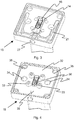
- a first connecting part 1 is shown with a female part 2 of a first embodiment of a connector.
- the first connecting part 1 has a bushing plate 3, which is provided centrally with a longitudinal opening 4, whereby the socket part 2 projects through and at the rear side of which the socket part 2 is fastened by means of non-apparent screws.
- On both sides and symmetrically to the socket part 2 four holes 5 are provided in a square, which are for receiving Allen screws (see FIG. 4 ) serve.
- two centering 6 are provided at a greater distance than the holes.
- the centering cams 6 are circular-cylindrical in the lower region 7 and conical in the upper region 8.
- the centering cams 6 are provided with an indentation 10 designed as an annular groove, which serves to receive a clip-shaped spring element (see FIG. 2 ) serves.
- the bushing plate 3 is screwed by means of Allen screws 11, for example, on a stand 13
- FIGS. 2 to 4 a second connecting part 15 are shown with a plug part 16 of the first embodiment of the connector.
- the second connecting part 15 has a plug plate 17, which has a central longitudinal opening 18 with widened, circularly rounded ends 19.
- this longitudinal opening 18 of the plug member 16 is embedded with its mounting plate 14 floating (see FIG. 3 ). Due to the floating attachment, the plug part 16 can exert a slight deflection in the longitudinal and in the transverse direction.
- the Plug plate 17 is further provided in the edge region of a U-shaped cutout 20, which serves to receive a clasp-shaped and U-shaped spring element 21.
- the spring element 21 is rod-shaped and has two straight legs 22 with free ends 23 and a slightly domed center part 24, which is located centrally in a transverse groove 25 of a slider 26 perpendicular thereto with an actuating means or push button 27.
- the slider 26 with the push button can be integrally formed.
- blind holes 28 are provided on both sides, which serve to receive the centering cam 6.
- On both sides of the central longitudinal opening 18 symmetrically four through holes 29 are mounted in the connector plate 17. At the four corner regions 30 of the connector plate 17 further four holes 31 are provided which serve to receive the Allen screws 11 of the first connection part 1.
- FIG. 4 is a cover plate 32 can be seen, which are screwed by means of Allen screws 33 in the through holes 29 of the connector plate 17.
- the cover plate 32 is screwed by means of Allen screws 33 in the through holes 29 of the connector plate 17.
- the bores 28 of the connector plate 17 are bores 34 and coincident with the bores 31 of the connector plate 17 angular recesses 35 are provided in the cover plate 32, so that the Allen screws 11 (see Fig. 1 ) can be recorded there.
- a longitudinal opening 36 is further inserted, which corresponds to the outer contour of the male part 16 with a small clearance.
- the mounting plate 14 of the male part 16 is held only by the longitudinal opening 18 of the connector plate 17 and the outer contour of the male part 16 of the longitudinal opening 36 of the adjoining cover plate 32 with a certain play without further attachment.
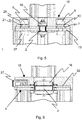
- FIGS. 5 and 6 Now show a cross section through the first connecting part 1 and the second connecting part 15 in the assembled state.
- the centering cams 6 are screwed on the back with a Allen screw 37 to the socket plate 3.
- the centering cam 6 serve for one-dimensional guidance in the connecting direction of the plug connection. So the first connection part 1 can be correctly mated with the second connection part 15, the socket part 4 and the plug part 16 have a trapezoidal outer contour.
- the centering cams 6 and the bores 30 are aligned slightly asymmetrically in the longitudinal direction of the socket part 4 and of the plug part 16.
- a character 38 in the form of a V provided on the socket plate 3 (see Fig. 1 ) and on the cover plate 32 (see Fig. 4 ) a character 38 in the form of a V provided.
- the clip-shaped spring element 21 is slightly pushed outwardly when inserted over the conical region 8 of the centering 6 and then engages in the formed as an annular groove 10 of the centering cams 6 a. It is understood that a simple indentation 10 may be provided, which is present only in the region of the latching of the spring element 21.
- the push button 27 is actuated, ie pressed inwards, as in FIG. 3 represented, whereby the two legs 22 are moved to the outside and thus the centering cams 6 are released.
- the second connecting part 15 can then be easily lifted from the first connecting part 1, so that at the same time the plug connection between the socket part 2 and the plug part 16 is released.
- the centering cam 6 with the annular groove 10 and the spring element 21 forms a releasable latching connection for the first connecting part 1 with the second connecting part 15th
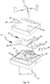
- a second embodiment of the connector is in the FIGS. 7 to 10 shown.
- a first connecting part 40 with a socket part 41 is made FIG. 7 seen.
- two centering cams 43 are fixed, which are formed with a longer circular cylindrical lower portion 44 and a conical upper portion 45. Between these two areas 44 and 45, a wide groove formed as an indentation 46 is provided.
- a second connecting part 48 is shown with a plug part 49 of the second embodiment in the assembled state.
- a rectangular cutout 51 is provided, which serves for the exception of a cuboid slide plate 52.
- the slide plate 52 is formed in the upper region with two lateral stops 56 for the coil springs 55 and with a lower cranked stop 57 for an actuating means or push button 58.
- the slide plate 52 also has centrally an upper opening 60 and a lower opening 61 which are aligned with the centering cams 43 and have a diameter of at least the diameter of the centering cams 43.
- the plug plate 50 is further provided with four holes (not shown) through which four Allen screws 62 inserted through and not visible in threaded holes) of a standpipe 75 are screwed.
- a trough-shaped cover plate 64 which has the holes 60 and 61 corresponding holes 65 and 66 is screwed with Allen screws 68 in threaded holes 69 of the connector plate 50.
- the second connecting part 48 can be plugged with the plug part 49 on the first connecting part 40 with the socket part 41.
- the socket part 41 and the plug part 49 are arranged at the edge.
- the centering cams 43 are also arranged slightly eccentrically on the axis perpendicular to the bushing part 41. The same applies to the openings 61 and 62 or the bores 65 and 66.
- the centering cam 43 and the slide plate 52 have the same function as in the first embodiment.
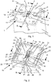
- FIGS. 11 to 16 Now various applications for the inventive connector with the first and second connecting part 1 and 15 or 40 and 48 are shown.
- FIG. 11 shows a ceiling light 70 with a four-edge mounting tube 71 to which the second connecting part 15 and 48 is attached.
- the first connection part 1 or 40 is attached to a ceiling (not shown).
- FIG. 12 the first connecting part 1 is shown with a cover 72 which is pushed over after the wall mounting of the first connecting part 1.
- the first connecting parts 1 are wired to the desired locations and fixed to the wall or ceiling and then protected with the covers 72, so that possible plasterer and painting work can be completed. Only in the final assembly of the lights with the second Connector 15 are then removed the covers 72.
- FIG. 13 is a table lamp 73 with the first connecting part 1, which is housed in a square tube 74, and the second connecting part 15, which is fastened to a four-edge standpipe 75 shown.
- a lamp body 76 is attached on the standpipe 75.
- the square tube 74 is mounted on a support plate 77 which can be mounted on a table top.
- the electrical leads are connected in the usual way via a cable channel with the first connecting part 1 (not shown).
- a floor lamp 80 is shown having the first connection part 1 housed in a square tube 81 and the second connection part 15 fixed to a four-edge standpipe 82.
- the square tube 81 has in one piece an H-shaped stand 83.
- the electrical supply line is formed here by a (not shown) electrical cable.
- FIG. 15 is a wall lamp 85 with the first connection part 1, which is fixed to a wall (not shown), and the second connection part 15, which is attached via a short square connecting pipe 86 with a lamp body 87, shown.
- FIG. 16 is a work table 90 with a worktop 91 and therein directly recessed first connecting parts 1 shown.
- the work lights 92 are then inserted as needed via the second connecting parts 15.
- Unused first connecting parts 1 can be protected by a cap (not shown)
- first connection part 1 or 40 and the second connection part 2 or 41 are made of chrome steel by laser beam and / or aluminum by milling.
- the centering cams 6 or 43 are also made of chrome steel.
- the electrical plug connection can also be formed by the two centering cams 6 or 45 and mating contacts, not shown, on the second connection part 15 or 48.
- the connector could be made via a single centering cam 6 or 45 with a coaxial connection. Since usually a transformer not shown here is present in the base 13, which provides a DC voltage of 24 V, such a connector is completely safe. In this case, the centering cams 6 or 45 must be fixed with an electrically insulating material opposite to the first connecting part 1 or 40.
Landscapes
- Engineering & Computer Science (AREA)
- General Engineering & Computer Science (AREA)
- Details Of Connecting Devices For Male And Female Coupling (AREA)
Applications Claiming Priority (1)
| Application Number | Priority Date | Filing Date | Title |
|---|---|---|---|
| CH01026/16A CH712795A2 (de) | 2016-08-10 | 2016-08-10 | Steckverbindung für einen Lampenkörper. |
Publications (2)
| Publication Number | Publication Date |
|---|---|
| EP3282178A1 true EP3282178A1 (fr) | 2018-02-14 |
| EP3282178B1 EP3282178B1 (fr) | 2020-04-29 |
Family
ID=59569224
Family Applications (1)
| Application Number | Title | Priority Date | Filing Date |
|---|---|---|---|
| EP17185403.7A Active EP3282178B1 (fr) | 2016-08-10 | 2017-08-08 | Connecteur pour un corps de la lampe |
Country Status (2)
| Country | Link |
|---|---|
| EP (1) | EP3282178B1 (fr) |
| CH (1) | CH712795A2 (fr) |
Families Citing this family (1)
| Publication number | Priority date | Publication date | Assignee | Title |
|---|---|---|---|---|
| USD953594S1 (en) * | 2021-01-20 | 2022-05-31 | Chuanqi Fu | Lamp |
Citations (3)
| Publication number | Priority date | Publication date | Assignee | Title |
|---|---|---|---|---|
| US6074235A (en) * | 1998-04-07 | 2000-06-13 | The Whitaker Corporation | Alignment post having an improved locking feature |
| US20060274519A1 (en) * | 2005-06-02 | 2006-12-07 | Pearce Richard A | Ceiling fan hanging system |
| EP2642613A2 (fr) * | 2012-03-20 | 2013-09-25 | Siteco Beleuchtungstechnik GmbH | Système de montage de lampes |
-
2016
- 2016-08-10 CH CH01026/16A patent/CH712795A2/de not_active Application Discontinuation
-
2017
- 2017-08-08 EP EP17185403.7A patent/EP3282178B1/fr active Active
Patent Citations (3)
| Publication number | Priority date | Publication date | Assignee | Title |
|---|---|---|---|---|
| US6074235A (en) * | 1998-04-07 | 2000-06-13 | The Whitaker Corporation | Alignment post having an improved locking feature |
| US20060274519A1 (en) * | 2005-06-02 | 2006-12-07 | Pearce Richard A | Ceiling fan hanging system |
| EP2642613A2 (fr) * | 2012-03-20 | 2013-09-25 | Siteco Beleuchtungstechnik GmbH | Système de montage de lampes |
Also Published As
| Publication number | Publication date |
|---|---|
| EP3282178B1 (fr) | 2020-04-29 |
| CH712795A2 (de) | 2018-02-15 |
Similar Documents
| Publication | Publication Date | Title |
|---|---|---|
| EP3345256B1 (fr) | Châssis de maintien pour module de connecteur à fiche comprenant un étrier de verrouillage qui peut être fixé | |
| DE10002947C1 (de) | Verriegelungseinrichtung zum Verriegeln eines elektronischen Geräts an einem Kabel | |
| DE10035996B4 (de) | Näherungsschalter | |
| EP3282178B1 (fr) | Connecteur pour un corps de la lampe | |
| EP1132676A2 (fr) | Dispositif de montage et de connexion électrique pour lampes | |
| EP0999409B1 (fr) | Appareil d'éclairage à encastrer avec une vasque de luminaire et un bras support pivotable | |
| EP2431659A1 (fr) | Lampe de projecteur | |
| DE102019109676A1 (de) | Haltefeder für Leuchte | |
| DE10013086A1 (de) | Einbauleuchte mit einem domförmigen Reflektor | |
| DE112015005935B4 (de) | Endkappe für eine Beleuchtungsvorrichtung und Beleuchtungsvorrichtung umfassend eine solche | |
| EP1586816A2 (fr) | Plafonnier | |
| EP1193806B1 (fr) | Dispositif de connexion, notamment pour rétroviseur extérieur de véhicule | |
| EP0507289B1 (fr) | Ferrure de connexion pour meubles | |
| EP3522303B1 (fr) | Bloc de raccordement | |
| DE19854440A1 (de) | Verlängerungsstück für Leuchtstofflampen | |
| DE10104757B4 (de) | Befestigungsvorrichtung zur verstellbaren Befestigung eines Fahrzeugteils | |
| DE102019130176B4 (de) | Steckverbinderteil mit einer Rasteinrichtung | |
| DE2717354C3 (de) | Verriegelung für Gehäuseteile eines elektrischen Installationsgerätes | |
| DE8424990U1 (de) | Näherungsschalter | |
| DE7618061U1 (de) | Verbindungsstueck zum loesbaren verbinden von wenigstens zwei elementen eines beleuchtungskoerpers | |
| EP0733746A2 (fr) | Support | |
| DE19528831A1 (de) | Montagevorrichtung für eine Leuchte | |
| EP1351559B1 (fr) | Système de fixation des composants électriques et/ou mécaniques d'un luminaire | |
| EP0297218A2 (fr) | Raccord enfichable | |
| EP0951106A2 (fr) | Connecteur à prises multiples avec support de montage ajustable |
Legal Events
| Date | Code | Title | Description |
|---|---|---|---|
| PUAI | Public reference made under article 153(3) epc to a published international application that has entered the european phase |
Free format text: ORIGINAL CODE: 0009012 |
|
| STAA | Information on the status of an ep patent application or granted ep patent |
Free format text: STATUS: THE APPLICATION HAS BEEN PUBLISHED |
|
| AK | Designated contracting states |
Kind code of ref document: A1 Designated state(s): AL AT BE BG CH CY CZ DE DK EE ES FI FR GB GR HR HU IE IS IT LI LT LU LV MC MK MT NL NO PL PT RO RS SE SI SK SM TR |
|
| AX | Request for extension of the european patent |
Extension state: BA ME |
|
| STAA | Information on the status of an ep patent application or granted ep patent |
Free format text: STATUS: REQUEST FOR EXAMINATION WAS MADE |
|
| 17P | Request for examination filed |
Effective date: 20180814 |
|
| RBV | Designated contracting states (corrected) |
Designated state(s): AL AT BE BG CH CY CZ DE DK EE ES FI FR GB GR HR HU IE IS IT LI LT LU LV MC MK MT NL NO PL PT RO RS SE SI SK SM TR |
|
| STAA | Information on the status of an ep patent application or granted ep patent |
Free format text: STATUS: EXAMINATION IS IN PROGRESS |
|
| 17Q | First examination report despatched |
Effective date: 20181016 |
|
| GRAP | Despatch of communication of intention to grant a patent |
Free format text: ORIGINAL CODE: EPIDOSNIGR1 |
|
| STAA | Information on the status of an ep patent application or granted ep patent |
Free format text: STATUS: GRANT OF PATENT IS INTENDED |
|
| INTG | Intention to grant announced |
Effective date: 20191126 |
|
| GRAS | Grant fee paid |
Free format text: ORIGINAL CODE: EPIDOSNIGR3 |
|
| GRAA | (expected) grant |
Free format text: ORIGINAL CODE: 0009210 |
|
| STAA | Information on the status of an ep patent application or granted ep patent |
Free format text: STATUS: THE PATENT HAS BEEN GRANTED |
|
| AK | Designated contracting states |
Kind code of ref document: B1 Designated state(s): AL AT BE BG CH CY CZ DE DK EE ES FI FR GB GR HR HU IE IS IT LI LT LU LV MC MK MT NL NO PL PT RO RS SE SI SK SM TR |
|
| REG | Reference to a national code |
Ref country code: GB Ref legal event code: FG4D Free format text: NOT ENGLISH |
|
| REG | Reference to a national code |
Ref country code: CH Ref legal event code: EP |
|
| REG | Reference to a national code |
Ref country code: DE Ref legal event code: R096 Ref document number: 502017004950 Country of ref document: DE |
|
| REG | Reference to a national code |
Ref country code: AT Ref legal event code: REF Ref document number: 1263862 Country of ref document: AT Kind code of ref document: T Effective date: 20200515 |
|
| REG | Reference to a national code |
Ref country code: IE Ref legal event code: FG4D Free format text: LANGUAGE OF EP DOCUMENT: GERMAN |
|
| REG | Reference to a national code |
Ref country code: CH Ref legal event code: NV Representative=s name: SPIERENBURG AND PARTNER AG, PATENT- UND MARKEN, CH |
|
| REG | Reference to a national code |
Ref country code: NL Ref legal event code: MP Effective date: 20200429 |
|
| REG | Reference to a national code |
Ref country code: LT Ref legal event code: MG4D |
|
| PG25 | Lapsed in a contracting state [announced via postgrant information from national office to epo] |
Ref country code: NO Free format text: LAPSE BECAUSE OF FAILURE TO SUBMIT A TRANSLATION OF THE DESCRIPTION OR TO PAY THE FEE WITHIN THE PRESCRIBED TIME-LIMIT Effective date: 20200729 Ref country code: IS Free format text: LAPSE BECAUSE OF FAILURE TO SUBMIT A TRANSLATION OF THE DESCRIPTION OR TO PAY THE FEE WITHIN THE PRESCRIBED TIME-LIMIT Effective date: 20200829 Ref country code: PT Free format text: LAPSE BECAUSE OF FAILURE TO SUBMIT A TRANSLATION OF THE DESCRIPTION OR TO PAY THE FEE WITHIN THE PRESCRIBED TIME-LIMIT Effective date: 20200831 Ref country code: LT Free format text: LAPSE BECAUSE OF FAILURE TO SUBMIT A TRANSLATION OF THE DESCRIPTION OR TO PAY THE FEE WITHIN THE PRESCRIBED TIME-LIMIT Effective date: 20200429 Ref country code: SE Free format text: LAPSE BECAUSE OF FAILURE TO SUBMIT A TRANSLATION OF THE DESCRIPTION OR TO PAY THE FEE WITHIN THE PRESCRIBED TIME-LIMIT Effective date: 20200429 Ref country code: GR Free format text: LAPSE BECAUSE OF FAILURE TO SUBMIT A TRANSLATION OF THE DESCRIPTION OR TO PAY THE FEE WITHIN THE PRESCRIBED TIME-LIMIT Effective date: 20200730 Ref country code: FI Free format text: LAPSE BECAUSE OF FAILURE TO SUBMIT A TRANSLATION OF THE DESCRIPTION OR TO PAY THE FEE WITHIN THE PRESCRIBED TIME-LIMIT Effective date: 20200429 |
|
| PG25 | Lapsed in a contracting state [announced via postgrant information from national office to epo] |
Ref country code: HR Free format text: LAPSE BECAUSE OF FAILURE TO SUBMIT A TRANSLATION OF THE DESCRIPTION OR TO PAY THE FEE WITHIN THE PRESCRIBED TIME-LIMIT Effective date: 20200429 Ref country code: LV Free format text: LAPSE BECAUSE OF FAILURE TO SUBMIT A TRANSLATION OF THE DESCRIPTION OR TO PAY THE FEE WITHIN THE PRESCRIBED TIME-LIMIT Effective date: 20200429 Ref country code: RS Free format text: LAPSE BECAUSE OF FAILURE TO SUBMIT A TRANSLATION OF THE DESCRIPTION OR TO PAY THE FEE WITHIN THE PRESCRIBED TIME-LIMIT Effective date: 20200429 Ref country code: BG Free format text: LAPSE BECAUSE OF FAILURE TO SUBMIT A TRANSLATION OF THE DESCRIPTION OR TO PAY THE FEE WITHIN THE PRESCRIBED TIME-LIMIT Effective date: 20200729 |
|
| PG25 | Lapsed in a contracting state [announced via postgrant information from national office to epo] |
Ref country code: AL Free format text: LAPSE BECAUSE OF FAILURE TO SUBMIT A TRANSLATION OF THE DESCRIPTION OR TO PAY THE FEE WITHIN THE PRESCRIBED TIME-LIMIT Effective date: 20200429 Ref country code: NL Free format text: LAPSE BECAUSE OF FAILURE TO SUBMIT A TRANSLATION OF THE DESCRIPTION OR TO PAY THE FEE WITHIN THE PRESCRIBED TIME-LIMIT Effective date: 20200429 |
|
| PG25 | Lapsed in a contracting state [announced via postgrant information from national office to epo] |
Ref country code: ES Free format text: LAPSE BECAUSE OF FAILURE TO SUBMIT A TRANSLATION OF THE DESCRIPTION OR TO PAY THE FEE WITHIN THE PRESCRIBED TIME-LIMIT Effective date: 20200429 Ref country code: CZ Free format text: LAPSE BECAUSE OF FAILURE TO SUBMIT A TRANSLATION OF THE DESCRIPTION OR TO PAY THE FEE WITHIN THE PRESCRIBED TIME-LIMIT Effective date: 20200429 Ref country code: RO Free format text: LAPSE BECAUSE OF FAILURE TO SUBMIT A TRANSLATION OF THE DESCRIPTION OR TO PAY THE FEE WITHIN THE PRESCRIBED TIME-LIMIT Effective date: 20200429 Ref country code: SM Free format text: LAPSE BECAUSE OF FAILURE TO SUBMIT A TRANSLATION OF THE DESCRIPTION OR TO PAY THE FEE WITHIN THE PRESCRIBED TIME-LIMIT Effective date: 20200429 Ref country code: EE Free format text: LAPSE BECAUSE OF FAILURE TO SUBMIT A TRANSLATION OF THE DESCRIPTION OR TO PAY THE FEE WITHIN THE PRESCRIBED TIME-LIMIT Effective date: 20200429 Ref country code: DK Free format text: LAPSE BECAUSE OF FAILURE TO SUBMIT A TRANSLATION OF THE DESCRIPTION OR TO PAY THE FEE WITHIN THE PRESCRIBED TIME-LIMIT Effective date: 20200429 Ref country code: IT Free format text: LAPSE BECAUSE OF FAILURE TO SUBMIT A TRANSLATION OF THE DESCRIPTION OR TO PAY THE FEE WITHIN THE PRESCRIBED TIME-LIMIT Effective date: 20200429 |
|
| REG | Reference to a national code |
Ref country code: DE Ref legal event code: R097 Ref document number: 502017004950 Country of ref document: DE |
|
| PG25 | Lapsed in a contracting state [announced via postgrant information from national office to epo] |
Ref country code: SK Free format text: LAPSE BECAUSE OF FAILURE TO SUBMIT A TRANSLATION OF THE DESCRIPTION OR TO PAY THE FEE WITHIN THE PRESCRIBED TIME-LIMIT Effective date: 20200429 Ref country code: PL Free format text: LAPSE BECAUSE OF FAILURE TO SUBMIT A TRANSLATION OF THE DESCRIPTION OR TO PAY THE FEE WITHIN THE PRESCRIBED TIME-LIMIT Effective date: 20200429 |
|
| PLBE | No opposition filed within time limit |
Free format text: ORIGINAL CODE: 0009261 |
|
| STAA | Information on the status of an ep patent application or granted ep patent |
Free format text: STATUS: NO OPPOSITION FILED WITHIN TIME LIMIT |
|
| PG25 | Lapsed in a contracting state [announced via postgrant information from national office to epo] |
Ref country code: MC Free format text: LAPSE BECAUSE OF FAILURE TO SUBMIT A TRANSLATION OF THE DESCRIPTION OR TO PAY THE FEE WITHIN THE PRESCRIBED TIME-LIMIT Effective date: 20200429 |
|
| 26N | No opposition filed |
Effective date: 20210201 |
|
| PG25 | Lapsed in a contracting state [announced via postgrant information from national office to epo] |
Ref country code: LU Free format text: LAPSE BECAUSE OF NON-PAYMENT OF DUE FEES Effective date: 20200808 |
|
| REG | Reference to a national code |
Ref country code: BE Ref legal event code: MM Effective date: 20200831 |
|
| PG25 | Lapsed in a contracting state [announced via postgrant information from national office to epo] |
Ref country code: SI Free format text: LAPSE BECAUSE OF FAILURE TO SUBMIT A TRANSLATION OF THE DESCRIPTION OR TO PAY THE FEE WITHIN THE PRESCRIBED TIME-LIMIT Effective date: 20200429 |
|
| PG25 | Lapsed in a contracting state [announced via postgrant information from national office to epo] |
Ref country code: IE Free format text: LAPSE BECAUSE OF NON-PAYMENT OF DUE FEES Effective date: 20200808 Ref country code: BE Free format text: LAPSE BECAUSE OF NON-PAYMENT OF DUE FEES Effective date: 20200831 |
|
| PG25 | Lapsed in a contracting state [announced via postgrant information from national office to epo] |
Ref country code: TR Free format text: LAPSE BECAUSE OF FAILURE TO SUBMIT A TRANSLATION OF THE DESCRIPTION OR TO PAY THE FEE WITHIN THE PRESCRIBED TIME-LIMIT Effective date: 20200429 Ref country code: MT Free format text: LAPSE BECAUSE OF FAILURE TO SUBMIT A TRANSLATION OF THE DESCRIPTION OR TO PAY THE FEE WITHIN THE PRESCRIBED TIME-LIMIT Effective date: 20200429 Ref country code: CY Free format text: LAPSE BECAUSE OF FAILURE TO SUBMIT A TRANSLATION OF THE DESCRIPTION OR TO PAY THE FEE WITHIN THE PRESCRIBED TIME-LIMIT Effective date: 20200429 |
|
| PG25 | Lapsed in a contracting state [announced via postgrant information from national office to epo] |
Ref country code: MK Free format text: LAPSE BECAUSE OF FAILURE TO SUBMIT A TRANSLATION OF THE DESCRIPTION OR TO PAY THE FEE WITHIN THE PRESCRIBED TIME-LIMIT Effective date: 20200429 |
|
| PGFP | Annual fee paid to national office [announced via postgrant information from national office to epo] |
Ref country code: CH Payment date: 20230902 Year of fee payment: 7 Ref country code: AT Payment date: 20230818 Year of fee payment: 7 |
|
| PGFP | Annual fee paid to national office [announced via postgrant information from national office to epo] |
Ref country code: DE Payment date: 20240819 Year of fee payment: 8 |
|
| PGFP | Annual fee paid to national office [announced via postgrant information from national office to epo] |
Ref country code: GB Payment date: 20240822 Year of fee payment: 8 |
|
| PGFP | Annual fee paid to national office [announced via postgrant information from national office to epo] |
Ref country code: FR Payment date: 20240823 Year of fee payment: 8 |