EP3282086A1 - Pompe, en particulier pompe a roue dentee destinee au transport d'auxiliaires technologiques - Google Patents
Pompe, en particulier pompe a roue dentee destinee au transport d'auxiliaires technologiques Download PDFInfo
- Publication number
- EP3282086A1 EP3282086A1 EP16183589.7A EP16183589A EP3282086A1 EP 3282086 A1 EP3282086 A1 EP 3282086A1 EP 16183589 A EP16183589 A EP 16183589A EP 3282086 A1 EP3282086 A1 EP 3282086A1
- Authority
- EP
- European Patent Office
- Prior art keywords
- pump
- processing aid
- unit
- drive unit
- drive
- Prior art date
- Legal status (The legal status is an assumption and is not a legal conclusion. Google has not performed a legal analysis and makes no representation as to the accuracy of the status listed.)
- Pending
Links
- 239000000654 additive Substances 0.000 title 1
- 239000006057 Non-nutritive feed additive Substances 0.000 claims abstract description 41
- 239000000126 substance Substances 0.000 claims abstract description 32
- 235000013305 food Nutrition 0.000 claims abstract description 16
- 239000012263 liquid product Substances 0.000 claims abstract description 13
- 238000005086 pumping Methods 0.000 claims abstract description 10
- 230000008878 coupling Effects 0.000 claims description 57
- 238000010168 coupling process Methods 0.000 claims description 57
- 238000005859 coupling reaction Methods 0.000 claims description 57
- 239000007788 liquid Substances 0.000 claims description 25
- 230000005540 biological transmission Effects 0.000 claims description 9
- 238000004519 manufacturing process Methods 0.000 claims description 5
- 238000000034 method Methods 0.000 claims description 5
- 239000012530 fluid Substances 0.000 claims description 4
- 238000007599 discharging Methods 0.000 claims description 3
- 229910000831 Steel Inorganic materials 0.000 claims description 2
- 229910001220 stainless steel Inorganic materials 0.000 claims description 2
- 239000010935 stainless steel Substances 0.000 claims description 2
- 239000010959 steel Substances 0.000 claims description 2
- 239000000463 material Substances 0.000 description 15
- 238000007789 sealing Methods 0.000 description 7
- 244000052616 bacterial pathogen Species 0.000 description 1
- 230000015572 biosynthetic process Effects 0.000 description 1
- 239000000839 emulsion Substances 0.000 description 1
- 230000008595 infiltration Effects 0.000 description 1
- 238000001764 infiltration Methods 0.000 description 1
- 230000003993 interaction Effects 0.000 description 1
- 230000002093 peripheral effect Effects 0.000 description 1
- 235000013311 vegetables Nutrition 0.000 description 1
Images


Classifications
-
- F—MECHANICAL ENGINEERING; LIGHTING; HEATING; WEAPONS; BLASTING
- F01—MACHINES OR ENGINES IN GENERAL; ENGINE PLANTS IN GENERAL; STEAM ENGINES
- F01C—ROTARY-PISTON OR OSCILLATING-PISTON MACHINES OR ENGINES
- F01C21/00—Component parts, details or accessories not provided for in groups F01C1/00 - F01C20/00
- F01C21/007—General arrangements of parts; Frames and supporting elements
-
- F—MECHANICAL ENGINEERING; LIGHTING; HEATING; WEAPONS; BLASTING
- F04—POSITIVE - DISPLACEMENT MACHINES FOR LIQUIDS; PUMPS FOR LIQUIDS OR ELASTIC FLUIDS
- F04C—ROTARY-PISTON, OR OSCILLATING-PISTON, POSITIVE-DISPLACEMENT MACHINES FOR LIQUIDS; ROTARY-PISTON, OR OSCILLATING-PISTON, POSITIVE-DISPLACEMENT PUMPS
- F04C13/00—Adaptations of machines or pumps for special use, e.g. for extremely high pressures
- F04C13/001—Pumps for particular liquids
-
- F—MECHANICAL ENGINEERING; LIGHTING; HEATING; WEAPONS; BLASTING
- F04—POSITIVE - DISPLACEMENT MACHINES FOR LIQUIDS; PUMPS FOR LIQUIDS OR ELASTIC FLUIDS
- F04C—ROTARY-PISTON, OR OSCILLATING-PISTON, POSITIVE-DISPLACEMENT MACHINES FOR LIQUIDS; ROTARY-PISTON, OR OSCILLATING-PISTON, POSITIVE-DISPLACEMENT PUMPS
- F04C13/00—Adaptations of machines or pumps for special use, e.g. for extremely high pressures
- F04C13/005—Removing contaminants, deposits or scale from the pump; Cleaning
-
- F—MECHANICAL ENGINEERING; LIGHTING; HEATING; WEAPONS; BLASTING
- F04—POSITIVE - DISPLACEMENT MACHINES FOR LIQUIDS; PUMPS FOR LIQUIDS OR ELASTIC FLUIDS
- F04C—ROTARY-PISTON, OR OSCILLATING-PISTON, POSITIVE-DISPLACEMENT MACHINES FOR LIQUIDS; ROTARY-PISTON, OR OSCILLATING-PISTON, POSITIVE-DISPLACEMENT PUMPS
- F04C14/00—Control of, monitoring of, or safety arrangements for, machines, pumps or pumping installations
- F04C14/28—Safety arrangements; Monitoring
-
- F—MECHANICAL ENGINEERING; LIGHTING; HEATING; WEAPONS; BLASTING
- F04—POSITIVE - DISPLACEMENT MACHINES FOR LIQUIDS; PUMPS FOR LIQUIDS OR ELASTIC FLUIDS
- F04C—ROTARY-PISTON, OR OSCILLATING-PISTON, POSITIVE-DISPLACEMENT MACHINES FOR LIQUIDS; ROTARY-PISTON, OR OSCILLATING-PISTON, POSITIVE-DISPLACEMENT PUMPS
- F04C15/00—Component parts, details or accessories of machines, pumps or pumping installations, not provided for in groups F04C2/00 - F04C14/00
- F04C15/0057—Driving elements, brakes, couplings, transmission specially adapted for machines or pumps
- F04C15/0061—Means for transmitting movement from the prime mover to driven parts of the pump, e.g. clutches, couplings, transmissions
- F04C15/0073—Couplings between rotors and input or output shafts acting by interengaging or mating parts, i.e. positive coupling of rotor and shaft
-
- F—MECHANICAL ENGINEERING; LIGHTING; HEATING; WEAPONS; BLASTING
- F04—POSITIVE - DISPLACEMENT MACHINES FOR LIQUIDS; PUMPS FOR LIQUIDS OR ELASTIC FLUIDS
- F04C—ROTARY-PISTON, OR OSCILLATING-PISTON, POSITIVE-DISPLACEMENT MACHINES FOR LIQUIDS; ROTARY-PISTON, OR OSCILLATING-PISTON, POSITIVE-DISPLACEMENT PUMPS
- F04C2/00—Rotary-piston machines or pumps
- F04C2/08—Rotary-piston machines or pumps of intermeshing-engagement type, i.e. with engagement of co-operating members similar to that of toothed gearing
-
- F—MECHANICAL ENGINEERING; LIGHTING; HEATING; WEAPONS; BLASTING
- F04—POSITIVE - DISPLACEMENT MACHINES FOR LIQUIDS; PUMPS FOR LIQUIDS OR ELASTIC FLUIDS
- F04C—ROTARY-PISTON, OR OSCILLATING-PISTON, POSITIVE-DISPLACEMENT MACHINES FOR LIQUIDS; ROTARY-PISTON, OR OSCILLATING-PISTON, POSITIVE-DISPLACEMENT PUMPS
- F04C2210/00—Fluid
- F04C2210/60—Condition
- F04C2210/62—Purity
-
- F—MECHANICAL ENGINEERING; LIGHTING; HEATING; WEAPONS; BLASTING
- F04—POSITIVE - DISPLACEMENT MACHINES FOR LIQUIDS; PUMPS FOR LIQUIDS OR ELASTIC FLUIDS
- F04C—ROTARY-PISTON, OR OSCILLATING-PISTON, POSITIVE-DISPLACEMENT MACHINES FOR LIQUIDS; ROTARY-PISTON, OR OSCILLATING-PISTON, POSITIVE-DISPLACEMENT PUMPS
- F04C2230/00—Manufacture
- F04C2230/70—Disassembly methods
-
- F—MECHANICAL ENGINEERING; LIGHTING; HEATING; WEAPONS; BLASTING
- F04—POSITIVE - DISPLACEMENT MACHINES FOR LIQUIDS; PUMPS FOR LIQUIDS OR ELASTIC FLUIDS
- F04C—ROTARY-PISTON, OR OSCILLATING-PISTON, POSITIVE-DISPLACEMENT MACHINES FOR LIQUIDS; ROTARY-PISTON, OR OSCILLATING-PISTON, POSITIVE-DISPLACEMENT PUMPS
- F04C2230/00—Manufacture
- F04C2230/80—Repairing methods
-
- F—MECHANICAL ENGINEERING; LIGHTING; HEATING; WEAPONS; BLASTING
- F04—POSITIVE - DISPLACEMENT MACHINES FOR LIQUIDS; PUMPS FOR LIQUIDS OR ELASTIC FLUIDS
- F04C—ROTARY-PISTON, OR OSCILLATING-PISTON, POSITIVE-DISPLACEMENT MACHINES FOR LIQUIDS; ROTARY-PISTON, OR OSCILLATING-PISTON, POSITIVE-DISPLACEMENT PUMPS
- F04C2240/00—Components
- F04C2240/80—Other components
- F04C2240/805—Fastening means, e.g. bolts
-
- F—MECHANICAL ENGINEERING; LIGHTING; HEATING; WEAPONS; BLASTING
- F04—POSITIVE - DISPLACEMENT MACHINES FOR LIQUIDS; PUMPS FOR LIQUIDS OR ELASTIC FLUIDS
- F04C—ROTARY-PISTON, OR OSCILLATING-PISTON, POSITIVE-DISPLACEMENT MACHINES FOR LIQUIDS; ROTARY-PISTON, OR OSCILLATING-PISTON, POSITIVE-DISPLACEMENT PUMPS
- F04C2280/00—Arrangements for preventing or removing deposits or corrosion
Definitions
- the invention relates to a pump, in particular gear pump, for conveying a processing aid, in particular liquid product, preferably for use in the food industry, chemical industry and / or pharmaceutical industry and a method for conveying a processing aid, in particular liquid product, preferably for use in the food industry, chemical industry and / or pharmaceutical industry.
- Gear pumps for conveying (liquid) substances are known in principle.
- the substance to be transported is transported in spaces between teeth and a wall surrounding the teeth.
- gear pumps or similar pumps for conveying materials for the food industry is not without problems, since there high hygiene standards must be met. High standards of purity and / or hygiene also often have to be met in the chemical or pharmaceutical industry.
- the object is achieved by a pump, in particular gear pump, for conveying a processing aid (hereinafter also referred to as "substance"), in particular liquid product (substance), preferably for use in the food industry, chemical industry and / or pharmaceutical industry, comprising a drive unit with a drive for providing a force and / or torque for pumping the processing aid and a pump unit in which the processing aid is pumpable, wherein the drive unit and the pump unit releasably, in particular without tools, connected or
- a basic idea of the invention is therefore to design the drive unit and pump unit such that they (in their entirety) can be connected to each other in a simple manner, in particular without the use of a tool.
- the pump unit need not be disassembled to disengage from the drive unit, but may be removed from the drive unit in its entirety (possibly after release of corresponding connection means such as clamps).
- drive unit and pump unit can be designed as modules that can be connected to one another. By separating from the drive unit, the pump unit can be cleaned in a particularly simple manner (for example in a dishwasher). As a result, even high hygiene requirements can be met in a simple manner.
- a pump in particular gear pump, preferably solved according to the first aspect, for conveying a processing aid, in particular liquid product, preferably for use in the food industry, chemical industry and / or pharmaceutical An industry, comprising a drive unit having a drive for providing a force and / or a torque for pumping the processing aid and a pump unit, in which the processing aid is pumpable, wherein at least one transmission element, in particular, at least one shaft, and / or a coupling part of the pump unit, which / serves the transmission of the driving force of the drive unit, by the processing aid and / or flow around.
- a core idea here is that a transmission element and / or a coupling part of the (liquid) material through and / or flows around. This means that in the area of the flow or flow, a continuous mass transfer takes place, so that the (liquid) material does not stay for a long time at a certain section. This easily and reliably prevents the formation of germs and the like, such as mold. This also satisfies the hygiene requirements in a reliable and simple manner. In particular, customarily occurring dead spaces into which the substance to be conveyed penetrates, but from which it is not removed again, can be reduced or even completely avoided.
- a pump in particular a gear pump
- a pump for conveying a processing aid, in particular liquid product, preferably for use in the food industry, chemical Industrial and / or pharmaceutical industry, comprising a drive unit with a drive for providing a force and / or torque for pumping the processing aid and a pump unit in which the processing aid is pumpable, wherein the pump unit is constructed (at least substantially) dead space-free and / or or dead spaces during operation are continuously um chandelier.
- flow through is to be understood in particular that during use of the pump steadily (at least a small part) of the substance flows through the respective part, thus entering at a first end of the part and exiting at a second end.
- a “flow around” is intended to be a flow that flows along a member or part referred to from a first end to a second end (during use of the pump). It should therefore in particular no inflow or infiltration be understood in a dead space, wherein the (liquid) material does not flow.
- the “flowing through” or “flowing around” thus relates in particular to the stationary state and not to a state in which the pump first receives the (liquid) substance.
- drive unit and pump unit are connected to one another by a plug connection or connectable.
- a coupling part (in particular magnetic coupling part) of the pump unit is inserted into a coupling part (in particular magnetic coupling part) of the drive unit.
- the drive unit and pump unit can be mounted on each other by an axial relative movement and / or be disassembled from each other.
- drive unit and pump unit are plugged together by an axial relative movement.
- an end of the pump unit facing the drive unit for example a corresponding coupling part (for example magnetic coupling part), can be plugged into the drive unit.
- the pump unit can be attached in its entirety to the drive unit (in its entirety) in a simple manner.
- At least one (detachable, in particular manually operable) locking device is provided. At least one such locking device can lock the pump unit and the drive unit to each other. Alternatively or additionally, at least one such locking device may be provided to lock individual elements of the pump unit (and / or individual elements of the drive unit) to each other.
- the locking device may comprise a clamping device, such as a clamp device and / or a tri-clamp device or generally joint clamping device (joint clip), eg single- and / or double-joint clamping device (two, three or more parts).
- a clamping device such as a clamp device and / or a tri-clamp device or generally joint clamping device (joint clip), eg single- and / or double-joint clamping device (two, three or more parts).
- a connection may comprise a plug connection and / or be effected by an axial relative movement of the elements to one another.
- a locking device may be provided, as has already been described in the preceding section.
- a "relative axial movement” is understood to mean a movement along the main axis of the drive unit, which is usually defined by a rotational axis of a rotating drive.
- a "main body” is to be understood in particular as meaning all elements of the pump unit (if appropriate apart from a wall or floor or cover element).
- the pump comprises a (non-contact) coupling, more preferably magnetic coupling, so that a driving force of the drive unit is transferable to the pump unit.
- the drive unit may have a magnetic coupling part and the pump unit has a corresponding magnetic coupling part.
- the magnetic coupling part of the drive unit may be bell-shaped or pot-shaped, in which case the magnetic coupling part of the pump unit is received in the magnetic coupling part of the drive unit.
- the conditions may also be reversed, that is to say in particular the magnetic coupling part of the drive unit can be accommodated or receivable in the magnetic coupling part of the pump unit.
- the drive unit may comprise an electric motor, in particular a (preferably brushless) DC motor. Furthermore, the drive unit may have a control device, for example with integrated speed control. Overall, a compact design is achieved.
- the pump unit may (at least substantially) be made of steel, in particular stainless steel, and / or plastic (possibly apart from seals, in particular sealing rings and / or sealing lips).
- the (entire) pump unit is made of dishwasher-proof material (possibly also seals, such as sealing rings and / or sealing lips).
- a drive shaft of a gear may be formed partially hollow.
- the driven gear (as part of the gear pump) may be at least partially hollow.
- the drive shaft and / or gear are formed so hollow that a fluid connection between the gear and a coupling part, in particular magnetic coupling part of the pump unit can be produced.
- both the gear and the drive shaft on an interconnected (axial) bore, in particular so that a fluid connection between a coupling part facing away from the end face of the gear and the coupling part facing the end of the drive shaft (to the coupling part) is realized ,
- (liquid) material from the coupling part to reach the opposite end of the gear (and thus also to the end of the gear or "under the gear), so that these sections of (liquid) material through or flow around.
- dead spaces with corresponding hygienic problems are reliably avoided.
- a (pressure-side) line for discharging the (liquid) substance may be connected to a connecting line which branches off from the (pressure-side) line.
- the connecting line can be designed such that it conveys a part of the (liquid) substance to at least one transmission and / or coupling part, in particular a magnetic coupling part. From the coupling part then, if necessary, the (liquid) material to one of the gears (the gear pump), for example, as described above, be promoted.
- the (liquid) material can be conveyed by a drive shaft of the toothed wheel and / or the toothed wheel itself and / or along a circumferential surface of the drive shaft (up to the toothed wheel).
- a circuit of one of the gears back to the gear can be formed, wherein the circuit is a portion of a (pressure side) line for discharging the (liquid) material, a connecting line to the coupling part and connections along and / or through the drive shaft and / or the gear comprises.
- the circuit is a portion of a (pressure side) line for discharging the (liquid) material, a connecting line to the coupling part and connections along and / or through the drive shaft and / or the gear comprises.
- the above object is further achieved by the use of a pump, in particular gear pump, of the type described above, for the Promotion of a (liquid) substance for the production of food.
- a pump in particular gear pump, of the type described above, for the Promotion of a (liquid) substance for the production of food.
- gear pump of the type described above
- a method for conveying a processing aid in particular a liquid product, preferably for use in the food industry, chemical industry and / or pharmaceutical industry, wherein the processing material with a pump, in particular gear pump, promoted the type described above becomes.
- At least one transmission element, in particular at least one shaft and / or a coupling part of the pump unit, which serves to transmit the driving force of the drive unit, can be flowed through and / or flow around the (liquid) substance.
- part of the (liquid) substance is branched off from a pressure-side line of the pump unit and led to the transmission element and / or the coupling part.
- a method for producing a pump, in particular gear pump, for conveying a processing aid, in particular a liquid product, preferably for use in the food industry, chemical industry and / or pharmaceutical industry, in particular of the type described above, comprising a drive unit with a drive for providing a force and / or a torque for pumping the processing aid liquid and a pump unit in which the processing aid liquid substance is pumpable, wherein the drive unit and the pump unit are stuck together and / or clamped and / or by an axial relative movement are connected .
- axial relative movement is meant in particular a purely translational movement.
- an “axial relative movement” can generally also be achieved by superimposing a rotational movement with a translatory (in the axial direction) movement, for example by turning (eg in a thread) or guiding within a slotted guide.
- the (liquid) substance may be frosting, (vegetable or animal) oil, an emulsion, a fat, in particular fluid fat, or the like.
- Fig. 1 shows a first embodiment of the gear pump according to the invention in an oblique view.
- Fig. 2 shows the gear pump according to Fig. 1 in a view from above.
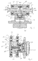
- FIG. 3 and FIG. 4 show sectional views of the gear pump according to Fig. 1 ,
- the gear pump according to the Fig. 1-4 has a drive unit 10 and a pump unit 11.
- the drive unit 10 comprises a (brushless) DC motor 12 and a first coupling part 13 (specifically, a clutch bell) which is driven (rotated) by the DC motor 12.
- the first coupling part 13 is a Magnetic coupling member.
- the rotational movement of the first coupling part 13 is transmitted via magnetic interaction to a second coupling part 14 (magnetic coupling part).
- the second coupling part 14 is part of the pump unit 11.
- the rotational movement of the second coupling part 14 is transmitted to a first gear 16 of the pump unit 11 (see Fig. 4 ).
- the first gear 16 in turn (see also Fig. 4 ) transmits its rotational movement to the second gear 17, which is mounted on a corresponding (second) shaft.
- a pump inlet 18 and a pump outlet 19 of the pump unit 11 can be seen.
- a suction-side line 20, the gears 16, 17 a (liquid) material is supplied.
- Via a pressure-side line 21, the (liquid) material is conveyed by the gears 16, 17 in the direction of the pump outlet 19.
- From the pressure-side line 21 branches off a connecting line 22, which connects the pressure-side line 21 with a portion 23 in which the second coupling part 14 is arranged.
- a diameter of the connecting line 22 is (clearly) smaller than a diameter of the pressure-side line 21 (for example by a factor of at least 2 or at least 4 smaller).
- the (liquid) material on the one hand by an axial bore 24 (see Fig. 4 ), which leads through the shaft 15 and the first gear 16, to an end 25 of the first gear 16, which faces away from the second coupling part 14, flow.
- the (liquid) substance may flow on an outer peripheral surface of the shaft 15.
- the pump unit 11 still has a cover element 26 (see 3 and 4 ) and a main body 27 (to which the second coupling part 14 can also be assigned in another way).
- the gears 16, 17 and the lines 20, 21 are arranged in the main body 27, the gears 16, 17 and the lines 20, 21 are arranged.
- Main body 27 (including second coupling part 14) may be connected to cover element 26 by a clamping device 28 (tri-clamp system).
- a clamping device 28 tri-clamp system
- the lid member 26 is applied to the main body 27.
- cover element 26 and main body 27 form an annular elevation 29, which is fixed by the clamping device 28.
- the clamp device 28 is via a manually operable actuator 34 (see Fig. 1 ), so that the lid member 26 can be removed from the main body 27 or mounted thereon.
- a sealing ring 30 are arranged between the cover member 26 and main body 27 (in the region of the annular elevation 29.
- the pump unit 11 can be plugged in (in the assembled state of the pump unit 11 or in their "entirety"). Specifically, the second coupling part 14 is inserted into the first coupling part 13. After forming this connector, an annular elevation 31, which is formed jointly by pump unit 11 and drive unit 10, a locking of the pump unit 11 to the drive unit 10 take place.
- a second clamping device 32 (Tri-clamp system) may be provided, which may be the same as the first clamping device 28.
- a sealing ring (second sealing ring) 33 may be formed between the pump unit 11 and the drive unit 10 (in the region of the second annular elevation 31).
- FIGS. 5 and 6 show a second embodiment of the gear pump according to the invention. This embodiment corresponds to the first embodiment, wherein the differences from the first embodiment will be explained below.
- the second embodiment eliminates the first clamp device. Furthermore, the main body 27 (at least partially) in the lid member 26 of the second embodiment (see Fig. 6 ).
- the lid member 26 according to the second embodiment is (in contrast to the first embodiment) not (essentially) as a plate, but cup-shaped. In general, the main body 27 can be plugged into the lid member 26 (in sections).
- the annular protrusion 31 does not become in the second embodiment formed by the main body 27 and drive unit 10, but by cover member 26 and drive unit 10. Overall, a comparatively simple structure is achieved in the second embodiment, which requires only one locking device, namely the second clamping device 32.
Landscapes
- Engineering & Computer Science (AREA)
- Mechanical Engineering (AREA)
- General Engineering & Computer Science (AREA)
- Rotary Pumps (AREA)
- Details And Applications Of Rotary Liquid Pumps (AREA)
Priority Applications (1)
| Application Number | Priority Date | Filing Date | Title |
|---|---|---|---|
| EP16183589.7A EP3282086A1 (fr) | 2016-08-10 | 2016-08-10 | Pompe, en particulier pompe a roue dentee destinee au transport d'auxiliaires technologiques |
Applications Claiming Priority (1)
| Application Number | Priority Date | Filing Date | Title |
|---|---|---|---|
| EP16183589.7A EP3282086A1 (fr) | 2016-08-10 | 2016-08-10 | Pompe, en particulier pompe a roue dentee destinee au transport d'auxiliaires technologiques |
Publications (1)
| Publication Number | Publication Date |
|---|---|
| EP3282086A1 true EP3282086A1 (fr) | 2018-02-14 |
Family
ID=56618080
Family Applications (1)
| Application Number | Title | Priority Date | Filing Date |
|---|---|---|---|
| EP16183589.7A Pending EP3282086A1 (fr) | 2016-08-10 | 2016-08-10 | Pompe, en particulier pompe a roue dentee destinee au transport d'auxiliaires technologiques |
Country Status (1)
| Country | Link |
|---|---|
| EP (1) | EP3282086A1 (fr) |
Cited By (1)
| Publication number | Priority date | Publication date | Assignee | Title |
|---|---|---|---|---|
| EP4170127A1 (fr) | 2021-10-22 | 2023-04-26 | A. u. K. Müller GmbH & Co. KG | Pompe à engrenage |
Citations (6)
| Publication number | Priority date | Publication date | Assignee | Title |
|---|---|---|---|---|
| DE1553115A1 (de) * | 1966-10-07 | 1970-07-16 | Ladish Co | Rotationspumpen |
| US5725362A (en) * | 1995-05-09 | 1998-03-10 | Xolox Corporation | Pump assembly |
| US20030129068A1 (en) * | 2002-01-10 | 2003-07-10 | Oehman Robert E. | Pump mount using sanitary flange clamp |
| GB2402975A (en) * | 2003-06-18 | 2004-12-22 | Carmeli Adahan | Rotary single vane pump with simplified vane-and-socket joint |
| US20060140793A1 (en) * | 2004-12-28 | 2006-06-29 | Micropump, Inc., A Unit Of Idex Corporation | Offset-drive magnetically driven gear-pump heads and gear pumps comprising same |
| US7309218B1 (en) * | 2004-11-10 | 2007-12-18 | Graham Louis Lewis | Gear pump |
-
2016
- 2016-08-10 EP EP16183589.7A patent/EP3282086A1/fr active Pending
Patent Citations (6)
| Publication number | Priority date | Publication date | Assignee | Title |
|---|---|---|---|---|
| DE1553115A1 (de) * | 1966-10-07 | 1970-07-16 | Ladish Co | Rotationspumpen |
| US5725362A (en) * | 1995-05-09 | 1998-03-10 | Xolox Corporation | Pump assembly |
| US20030129068A1 (en) * | 2002-01-10 | 2003-07-10 | Oehman Robert E. | Pump mount using sanitary flange clamp |
| GB2402975A (en) * | 2003-06-18 | 2004-12-22 | Carmeli Adahan | Rotary single vane pump with simplified vane-and-socket joint |
| US7309218B1 (en) * | 2004-11-10 | 2007-12-18 | Graham Louis Lewis | Gear pump |
| US20060140793A1 (en) * | 2004-12-28 | 2006-06-29 | Micropump, Inc., A Unit Of Idex Corporation | Offset-drive magnetically driven gear-pump heads and gear pumps comprising same |
Cited By (1)
| Publication number | Priority date | Publication date | Assignee | Title |
|---|---|---|---|---|
| EP4170127A1 (fr) | 2021-10-22 | 2023-04-26 | A. u. K. Müller GmbH & Co. KG | Pompe à engrenage |
Similar Documents
| Publication | Publication Date | Title |
|---|---|---|
| EP2944819B1 (fr) | Pompe à vis sans fin excentrique | |
| EP2091851B1 (fr) | Rouleau de transport avec fonction de nettoyage | |
| DE2202808A1 (de) | Verfahren zur herstellung von rohrleitungsanschluessen | |
| DE20107206U1 (de) | Antriebsvorrichtung für eine Greifeinrichtung | |
| DE4019746C1 (fr) | ||
| EP2022571A1 (fr) | Dispositif de dosage destiné au dosage d'un liquide | |
| EP3282086A1 (fr) | Pompe, en particulier pompe a roue dentee destinee au transport d'auxiliaires technologiques | |
| DE102005032301B4 (de) | Innen und außen kerbverzahnte Kupplungsnabe für Drehmomentübertragungsmechanismen in einem Lastschaltgetriebe | |
| EP3117868A1 (fr) | Dispositif de raccordement pour le traitement de plaies et kit de traitement de plaies | |
| DE112018002689B4 (de) | Filteranordnung und Verfahren zum Herstellen einer Filteranordnung | |
| EP0085952B1 (fr) | Tuyau à conduits hydrauliques ou pneumatiques multiples avec raccord multiple | |
| EP1502724B1 (fr) | Filtre pour machines de traitement, spécialement extrudeuses | |
| DE3728821C1 (de) | Bolzengelenk fuer Exzenterschneckenpumpen | |
| DE102008058675B4 (de) | Steckverbindung | |
| DE2120331A1 (de) | Gehäuse | |
| EP1177389A1 (fr) | Dispositif recepteur pour au moins un arbre monte de maniere etanche dans un carter | |
| DE19856534A1 (de) | Getriebe für einen Doppelschneckenextruder | |
| DE2845926C2 (de) | Kupplung für mehradrige Schlauchleitungen, insbesondere hydraulische Hochdruckschlauchleitungen | |
| EP3725344A1 (fr) | Agencement de chambre de gouttement pour un système de perfusion médicale et procédé de production d'un tel agencement de chambre de gouttement | |
| DE102019213522A1 (de) | Getriebeölmodul für eine Getriebeeinrichtung | |
| EP1083336A2 (fr) | Pompe moineau et dispositif de connexion | |
| EP1988289A1 (fr) | Interface | |
| EP1445490B1 (fr) | Dispositif de pompage | |
| EP3479460A1 (fr) | Unité d'entraînement pour un tambour moteur, tambour moteur, flasque arrière et procédés de production | |
| DE102020106026A1 (de) | Vorrichtung zur Förderung von Fließgut und Verfahren zum Betrieb |
Legal Events
| Date | Code | Title | Description |
|---|---|---|---|
| PUAI | Public reference made under article 153(3) epc to a published international application that has entered the european phase |
Free format text: ORIGINAL CODE: 0009012 |
|
| STAA | Information on the status of an ep patent application or granted ep patent |
Free format text: STATUS: THE APPLICATION HAS BEEN PUBLISHED |
|
| AK | Designated contracting states |
Kind code of ref document: A1 Designated state(s): AL AT BE BG CH CY CZ DE DK EE ES FI FR GB GR HR HU IE IS IT LI LT LU LV MC MK MT NL NO PL PT RO RS SE SI SK SM TR |
|
| AX | Request for extension of the european patent |
Extension state: BA ME |
|
| STAA | Information on the status of an ep patent application or granted ep patent |
Free format text: STATUS: REQUEST FOR EXAMINATION WAS MADE |
|
| 17P | Request for examination filed |
Effective date: 20180803 |
|
| RBV | Designated contracting states (corrected) |
Designated state(s): AL AT BE BG CH CY CZ DE DK EE ES FI FR GB GR HR HU IE IS IT LI LT LU LV MC MK MT NL NO PL PT RO RS SE SI SK SM TR |
|
| RAP1 | Party data changed (applicant data changed or rights of an application transferred) |
Owner name: GROENEVELD-BEKA GMBH |
|
| STAA | Information on the status of an ep patent application or granted ep patent |
Free format text: STATUS: EXAMINATION IS IN PROGRESS |
|
| 17Q | First examination report despatched |
Effective date: 20210601 |
|
| STAA | Information on the status of an ep patent application or granted ep patent |
Free format text: STATUS: EXAMINATION IS IN PROGRESS |
|
| GRAP | Despatch of communication of intention to grant a patent |
Free format text: ORIGINAL CODE: EPIDOSNIGR1 |
|
| STAA | Information on the status of an ep patent application or granted ep patent |
Free format text: STATUS: GRANT OF PATENT IS INTENDED |
|
| INTG | Intention to grant announced |
Effective date: 20240305 |