EP3282086A1 - Pump, in particular gear pump, for conveying of additives - Google Patents
Pump, in particular gear pump, for conveying of additives Download PDFInfo
- Publication number
- EP3282086A1 EP3282086A1 EP16183589.7A EP16183589A EP3282086A1 EP 3282086 A1 EP3282086 A1 EP 3282086A1 EP 16183589 A EP16183589 A EP 16183589A EP 3282086 A1 EP3282086 A1 EP 3282086A1
- Authority
- EP
- European Patent Office
- Prior art keywords
- pump
- processing aid
- unit
- drive unit
- drive
- Prior art date
- Legal status (The legal status is an assumption and is not a legal conclusion. Google has not performed a legal analysis and makes no representation as to the accuracy of the status listed.)
- Pending
Links
- 239000000654 additive Substances 0.000 title 1
- 239000006057 Non-nutritive feed additive Substances 0.000 claims abstract description 41
- 239000000126 substance Substances 0.000 claims abstract description 32
- 235000013305 food Nutrition 0.000 claims abstract description 16
- 239000012263 liquid product Substances 0.000 claims abstract description 13
- 238000005086 pumping Methods 0.000 claims abstract description 10
- 230000008878 coupling Effects 0.000 claims description 57
- 238000010168 coupling process Methods 0.000 claims description 57
- 238000005859 coupling reaction Methods 0.000 claims description 57
- 239000007788 liquid Substances 0.000 claims description 25
- 230000005540 biological transmission Effects 0.000 claims description 9
- 238000004519 manufacturing process Methods 0.000 claims description 5
- 238000000034 method Methods 0.000 claims description 5
- 239000012530 fluid Substances 0.000 claims description 4
- 238000007599 discharging Methods 0.000 claims description 3
- 229910000831 Steel Inorganic materials 0.000 claims description 2
- 229910001220 stainless steel Inorganic materials 0.000 claims description 2
- 239000010935 stainless steel Substances 0.000 claims description 2
- 239000010959 steel Substances 0.000 claims description 2
- 239000000463 material Substances 0.000 description 15
- 238000007789 sealing Methods 0.000 description 7
- 244000052616 bacterial pathogen Species 0.000 description 1
- 230000015572 biosynthetic process Effects 0.000 description 1
- 239000000839 emulsion Substances 0.000 description 1
- 230000008595 infiltration Effects 0.000 description 1
- 238000001764 infiltration Methods 0.000 description 1
- 230000003993 interaction Effects 0.000 description 1
- 230000002093 peripheral effect Effects 0.000 description 1
- 235000013311 vegetables Nutrition 0.000 description 1
Images


Classifications
-
- F—MECHANICAL ENGINEERING; LIGHTING; HEATING; WEAPONS; BLASTING
- F01—MACHINES OR ENGINES IN GENERAL; ENGINE PLANTS IN GENERAL; STEAM ENGINES
- F01C—ROTARY-PISTON OR OSCILLATING-PISTON MACHINES OR ENGINES
- F01C21/00—Component parts, details or accessories not provided for in groups F01C1/00 - F01C20/00
- F01C21/007—General arrangements of parts; Frames and supporting elements
-
- F—MECHANICAL ENGINEERING; LIGHTING; HEATING; WEAPONS; BLASTING
- F04—POSITIVE - DISPLACEMENT MACHINES FOR LIQUIDS; PUMPS FOR LIQUIDS OR ELASTIC FLUIDS
- F04C—ROTARY-PISTON, OR OSCILLATING-PISTON, POSITIVE-DISPLACEMENT MACHINES FOR LIQUIDS; ROTARY-PISTON, OR OSCILLATING-PISTON, POSITIVE-DISPLACEMENT PUMPS
- F04C13/00—Adaptations of machines or pumps for special use, e.g. for extremely high pressures
- F04C13/001—Pumps for particular liquids
-
- F—MECHANICAL ENGINEERING; LIGHTING; HEATING; WEAPONS; BLASTING
- F04—POSITIVE - DISPLACEMENT MACHINES FOR LIQUIDS; PUMPS FOR LIQUIDS OR ELASTIC FLUIDS
- F04C—ROTARY-PISTON, OR OSCILLATING-PISTON, POSITIVE-DISPLACEMENT MACHINES FOR LIQUIDS; ROTARY-PISTON, OR OSCILLATING-PISTON, POSITIVE-DISPLACEMENT PUMPS
- F04C13/00—Adaptations of machines or pumps for special use, e.g. for extremely high pressures
- F04C13/005—Removing contaminants, deposits or scale from the pump; Cleaning
-
- F—MECHANICAL ENGINEERING; LIGHTING; HEATING; WEAPONS; BLASTING
- F04—POSITIVE - DISPLACEMENT MACHINES FOR LIQUIDS; PUMPS FOR LIQUIDS OR ELASTIC FLUIDS
- F04C—ROTARY-PISTON, OR OSCILLATING-PISTON, POSITIVE-DISPLACEMENT MACHINES FOR LIQUIDS; ROTARY-PISTON, OR OSCILLATING-PISTON, POSITIVE-DISPLACEMENT PUMPS
- F04C14/00—Control of, monitoring of, or safety arrangements for, machines, pumps or pumping installations
- F04C14/28—Safety arrangements; Monitoring
-
- F—MECHANICAL ENGINEERING; LIGHTING; HEATING; WEAPONS; BLASTING
- F04—POSITIVE - DISPLACEMENT MACHINES FOR LIQUIDS; PUMPS FOR LIQUIDS OR ELASTIC FLUIDS
- F04C—ROTARY-PISTON, OR OSCILLATING-PISTON, POSITIVE-DISPLACEMENT MACHINES FOR LIQUIDS; ROTARY-PISTON, OR OSCILLATING-PISTON, POSITIVE-DISPLACEMENT PUMPS
- F04C15/00—Component parts, details or accessories of machines, pumps or pumping installations, not provided for in groups F04C2/00 - F04C14/00
- F04C15/0057—Driving elements, brakes, couplings, transmission specially adapted for machines or pumps
- F04C15/0061—Means for transmitting movement from the prime mover to driven parts of the pump, e.g. clutches, couplings, transmissions
- F04C15/0073—Couplings between rotors and input or output shafts acting by interengaging or mating parts, i.e. positive coupling of rotor and shaft
-
- F—MECHANICAL ENGINEERING; LIGHTING; HEATING; WEAPONS; BLASTING
- F04—POSITIVE - DISPLACEMENT MACHINES FOR LIQUIDS; PUMPS FOR LIQUIDS OR ELASTIC FLUIDS
- F04C—ROTARY-PISTON, OR OSCILLATING-PISTON, POSITIVE-DISPLACEMENT MACHINES FOR LIQUIDS; ROTARY-PISTON, OR OSCILLATING-PISTON, POSITIVE-DISPLACEMENT PUMPS
- F04C2/00—Rotary-piston machines or pumps
- F04C2/08—Rotary-piston machines or pumps of intermeshing-engagement type, i.e. with engagement of co-operating members similar to that of toothed gearing
-
- F—MECHANICAL ENGINEERING; LIGHTING; HEATING; WEAPONS; BLASTING
- F04—POSITIVE - DISPLACEMENT MACHINES FOR LIQUIDS; PUMPS FOR LIQUIDS OR ELASTIC FLUIDS
- F04C—ROTARY-PISTON, OR OSCILLATING-PISTON, POSITIVE-DISPLACEMENT MACHINES FOR LIQUIDS; ROTARY-PISTON, OR OSCILLATING-PISTON, POSITIVE-DISPLACEMENT PUMPS
- F04C2210/00—Fluid
- F04C2210/60—Condition
- F04C2210/62—Purity
-
- F—MECHANICAL ENGINEERING; LIGHTING; HEATING; WEAPONS; BLASTING
- F04—POSITIVE - DISPLACEMENT MACHINES FOR LIQUIDS; PUMPS FOR LIQUIDS OR ELASTIC FLUIDS
- F04C—ROTARY-PISTON, OR OSCILLATING-PISTON, POSITIVE-DISPLACEMENT MACHINES FOR LIQUIDS; ROTARY-PISTON, OR OSCILLATING-PISTON, POSITIVE-DISPLACEMENT PUMPS
- F04C2230/00—Manufacture
- F04C2230/70—Disassembly methods
-
- F—MECHANICAL ENGINEERING; LIGHTING; HEATING; WEAPONS; BLASTING
- F04—POSITIVE - DISPLACEMENT MACHINES FOR LIQUIDS; PUMPS FOR LIQUIDS OR ELASTIC FLUIDS
- F04C—ROTARY-PISTON, OR OSCILLATING-PISTON, POSITIVE-DISPLACEMENT MACHINES FOR LIQUIDS; ROTARY-PISTON, OR OSCILLATING-PISTON, POSITIVE-DISPLACEMENT PUMPS
- F04C2230/00—Manufacture
- F04C2230/80—Repairing methods
-
- F—MECHANICAL ENGINEERING; LIGHTING; HEATING; WEAPONS; BLASTING
- F04—POSITIVE - DISPLACEMENT MACHINES FOR LIQUIDS; PUMPS FOR LIQUIDS OR ELASTIC FLUIDS
- F04C—ROTARY-PISTON, OR OSCILLATING-PISTON, POSITIVE-DISPLACEMENT MACHINES FOR LIQUIDS; ROTARY-PISTON, OR OSCILLATING-PISTON, POSITIVE-DISPLACEMENT PUMPS
- F04C2240/00—Components
- F04C2240/80—Other components
- F04C2240/805—Fastening means, e.g. bolts
-
- F—MECHANICAL ENGINEERING; LIGHTING; HEATING; WEAPONS; BLASTING
- F04—POSITIVE - DISPLACEMENT MACHINES FOR LIQUIDS; PUMPS FOR LIQUIDS OR ELASTIC FLUIDS
- F04C—ROTARY-PISTON, OR OSCILLATING-PISTON, POSITIVE-DISPLACEMENT MACHINES FOR LIQUIDS; ROTARY-PISTON, OR OSCILLATING-PISTON, POSITIVE-DISPLACEMENT PUMPS
- F04C2280/00—Arrangements for preventing or removing deposits or corrosion
Definitions
- the invention relates to a pump, in particular gear pump, for conveying a processing aid, in particular liquid product, preferably for use in the food industry, chemical industry and / or pharmaceutical industry and a method for conveying a processing aid, in particular liquid product, preferably for use in the food industry, chemical industry and / or pharmaceutical industry.
- Gear pumps for conveying (liquid) substances are known in principle.
- the substance to be transported is transported in spaces between teeth and a wall surrounding the teeth.
- gear pumps or similar pumps for conveying materials for the food industry is not without problems, since there high hygiene standards must be met. High standards of purity and / or hygiene also often have to be met in the chemical or pharmaceutical industry.
- the object is achieved by a pump, in particular gear pump, for conveying a processing aid (hereinafter also referred to as "substance"), in particular liquid product (substance), preferably for use in the food industry, chemical industry and / or pharmaceutical industry, comprising a drive unit with a drive for providing a force and / or torque for pumping the processing aid and a pump unit in which the processing aid is pumpable, wherein the drive unit and the pump unit releasably, in particular without tools, connected or
- a basic idea of the invention is therefore to design the drive unit and pump unit such that they (in their entirety) can be connected to each other in a simple manner, in particular without the use of a tool.
- the pump unit need not be disassembled to disengage from the drive unit, but may be removed from the drive unit in its entirety (possibly after release of corresponding connection means such as clamps).
- drive unit and pump unit can be designed as modules that can be connected to one another. By separating from the drive unit, the pump unit can be cleaned in a particularly simple manner (for example in a dishwasher). As a result, even high hygiene requirements can be met in a simple manner.
- a pump in particular gear pump, preferably solved according to the first aspect, for conveying a processing aid, in particular liquid product, preferably for use in the food industry, chemical industry and / or pharmaceutical An industry, comprising a drive unit having a drive for providing a force and / or a torque for pumping the processing aid and a pump unit, in which the processing aid is pumpable, wherein at least one transmission element, in particular, at least one shaft, and / or a coupling part of the pump unit, which / serves the transmission of the driving force of the drive unit, by the processing aid and / or flow around.
- a core idea here is that a transmission element and / or a coupling part of the (liquid) material through and / or flows around. This means that in the area of the flow or flow, a continuous mass transfer takes place, so that the (liquid) material does not stay for a long time at a certain section. This easily and reliably prevents the formation of germs and the like, such as mold. This also satisfies the hygiene requirements in a reliable and simple manner. In particular, customarily occurring dead spaces into which the substance to be conveyed penetrates, but from which it is not removed again, can be reduced or even completely avoided.
- a pump in particular a gear pump
- a pump for conveying a processing aid, in particular liquid product, preferably for use in the food industry, chemical Industrial and / or pharmaceutical industry, comprising a drive unit with a drive for providing a force and / or torque for pumping the processing aid and a pump unit in which the processing aid is pumpable, wherein the pump unit is constructed (at least substantially) dead space-free and / or or dead spaces during operation are continuously um chandelier.
- flow through is to be understood in particular that during use of the pump steadily (at least a small part) of the substance flows through the respective part, thus entering at a first end of the part and exiting at a second end.
- a “flow around” is intended to be a flow that flows along a member or part referred to from a first end to a second end (during use of the pump). It should therefore in particular no inflow or infiltration be understood in a dead space, wherein the (liquid) material does not flow.
- the “flowing through” or “flowing around” thus relates in particular to the stationary state and not to a state in which the pump first receives the (liquid) substance.
- drive unit and pump unit are connected to one another by a plug connection or connectable.
- a coupling part (in particular magnetic coupling part) of the pump unit is inserted into a coupling part (in particular magnetic coupling part) of the drive unit.
- the drive unit and pump unit can be mounted on each other by an axial relative movement and / or be disassembled from each other.
- drive unit and pump unit are plugged together by an axial relative movement.
- an end of the pump unit facing the drive unit for example a corresponding coupling part (for example magnetic coupling part), can be plugged into the drive unit.
- the pump unit can be attached in its entirety to the drive unit (in its entirety) in a simple manner.
- At least one (detachable, in particular manually operable) locking device is provided. At least one such locking device can lock the pump unit and the drive unit to each other. Alternatively or additionally, at least one such locking device may be provided to lock individual elements of the pump unit (and / or individual elements of the drive unit) to each other.
- the locking device may comprise a clamping device, such as a clamp device and / or a tri-clamp device or generally joint clamping device (joint clip), eg single- and / or double-joint clamping device (two, three or more parts).
- a clamping device such as a clamp device and / or a tri-clamp device or generally joint clamping device (joint clip), eg single- and / or double-joint clamping device (two, three or more parts).
- a connection may comprise a plug connection and / or be effected by an axial relative movement of the elements to one another.
- a locking device may be provided, as has already been described in the preceding section.
- a "relative axial movement” is understood to mean a movement along the main axis of the drive unit, which is usually defined by a rotational axis of a rotating drive.
- a "main body” is to be understood in particular as meaning all elements of the pump unit (if appropriate apart from a wall or floor or cover element).
- the pump comprises a (non-contact) coupling, more preferably magnetic coupling, so that a driving force of the drive unit is transferable to the pump unit.
- the drive unit may have a magnetic coupling part and the pump unit has a corresponding magnetic coupling part.
- the magnetic coupling part of the drive unit may be bell-shaped or pot-shaped, in which case the magnetic coupling part of the pump unit is received in the magnetic coupling part of the drive unit.
- the conditions may also be reversed, that is to say in particular the magnetic coupling part of the drive unit can be accommodated or receivable in the magnetic coupling part of the pump unit.
- the drive unit may comprise an electric motor, in particular a (preferably brushless) DC motor. Furthermore, the drive unit may have a control device, for example with integrated speed control. Overall, a compact design is achieved.
- the pump unit may (at least substantially) be made of steel, in particular stainless steel, and / or plastic (possibly apart from seals, in particular sealing rings and / or sealing lips).
- the (entire) pump unit is made of dishwasher-proof material (possibly also seals, such as sealing rings and / or sealing lips).
- a drive shaft of a gear may be formed partially hollow.
- the driven gear (as part of the gear pump) may be at least partially hollow.
- the drive shaft and / or gear are formed so hollow that a fluid connection between the gear and a coupling part, in particular magnetic coupling part of the pump unit can be produced.
- both the gear and the drive shaft on an interconnected (axial) bore, in particular so that a fluid connection between a coupling part facing away from the end face of the gear and the coupling part facing the end of the drive shaft (to the coupling part) is realized ,
- (liquid) material from the coupling part to reach the opposite end of the gear (and thus also to the end of the gear or "under the gear), so that these sections of (liquid) material through or flow around.
- dead spaces with corresponding hygienic problems are reliably avoided.
- a (pressure-side) line for discharging the (liquid) substance may be connected to a connecting line which branches off from the (pressure-side) line.
- the connecting line can be designed such that it conveys a part of the (liquid) substance to at least one transmission and / or coupling part, in particular a magnetic coupling part. From the coupling part then, if necessary, the (liquid) material to one of the gears (the gear pump), for example, as described above, be promoted.
- the (liquid) material can be conveyed by a drive shaft of the toothed wheel and / or the toothed wheel itself and / or along a circumferential surface of the drive shaft (up to the toothed wheel).
- a circuit of one of the gears back to the gear can be formed, wherein the circuit is a portion of a (pressure side) line for discharging the (liquid) material, a connecting line to the coupling part and connections along and / or through the drive shaft and / or the gear comprises.
- the circuit is a portion of a (pressure side) line for discharging the (liquid) material, a connecting line to the coupling part and connections along and / or through the drive shaft and / or the gear comprises.
- the above object is further achieved by the use of a pump, in particular gear pump, of the type described above, for the Promotion of a (liquid) substance for the production of food.
- a pump in particular gear pump, of the type described above, for the Promotion of a (liquid) substance for the production of food.
- gear pump of the type described above
- a method for conveying a processing aid in particular a liquid product, preferably for use in the food industry, chemical industry and / or pharmaceutical industry, wherein the processing material with a pump, in particular gear pump, promoted the type described above becomes.
- At least one transmission element, in particular at least one shaft and / or a coupling part of the pump unit, which serves to transmit the driving force of the drive unit, can be flowed through and / or flow around the (liquid) substance.
- part of the (liquid) substance is branched off from a pressure-side line of the pump unit and led to the transmission element and / or the coupling part.
- a method for producing a pump, in particular gear pump, for conveying a processing aid, in particular a liquid product, preferably for use in the food industry, chemical industry and / or pharmaceutical industry, in particular of the type described above, comprising a drive unit with a drive for providing a force and / or a torque for pumping the processing aid liquid and a pump unit in which the processing aid liquid substance is pumpable, wherein the drive unit and the pump unit are stuck together and / or clamped and / or by an axial relative movement are connected .
- axial relative movement is meant in particular a purely translational movement.
- an “axial relative movement” can generally also be achieved by superimposing a rotational movement with a translatory (in the axial direction) movement, for example by turning (eg in a thread) or guiding within a slotted guide.
- the (liquid) substance may be frosting, (vegetable or animal) oil, an emulsion, a fat, in particular fluid fat, or the like.
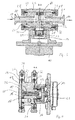
- Fig. 1 shows a first embodiment of the gear pump according to the invention in an oblique view.
- Fig. 2 shows the gear pump according to Fig. 1 in a view from above.
- FIG. 3 and FIG. 4 show sectional views of the gear pump according to Fig. 1 ,
- the gear pump according to the Fig. 1-4 has a drive unit 10 and a pump unit 11.
- the drive unit 10 comprises a (brushless) DC motor 12 and a first coupling part 13 (specifically, a clutch bell) which is driven (rotated) by the DC motor 12.
- the first coupling part 13 is a Magnetic coupling member.
- the rotational movement of the first coupling part 13 is transmitted via magnetic interaction to a second coupling part 14 (magnetic coupling part).
- the second coupling part 14 is part of the pump unit 11.
- the rotational movement of the second coupling part 14 is transmitted to a first gear 16 of the pump unit 11 (see Fig. 4 ).
- the first gear 16 in turn (see also Fig. 4 ) transmits its rotational movement to the second gear 17, which is mounted on a corresponding (second) shaft.
- a pump inlet 18 and a pump outlet 19 of the pump unit 11 can be seen.
- a suction-side line 20, the gears 16, 17 a (liquid) material is supplied.
- Via a pressure-side line 21, the (liquid) material is conveyed by the gears 16, 17 in the direction of the pump outlet 19.
- From the pressure-side line 21 branches off a connecting line 22, which connects the pressure-side line 21 with a portion 23 in which the second coupling part 14 is arranged.
- a diameter of the connecting line 22 is (clearly) smaller than a diameter of the pressure-side line 21 (for example by a factor of at least 2 or at least 4 smaller).
- the (liquid) material on the one hand by an axial bore 24 (see Fig. 4 ), which leads through the shaft 15 and the first gear 16, to an end 25 of the first gear 16, which faces away from the second coupling part 14, flow.
- the (liquid) substance may flow on an outer peripheral surface of the shaft 15.
- the pump unit 11 still has a cover element 26 (see 3 and 4 ) and a main body 27 (to which the second coupling part 14 can also be assigned in another way).
- the gears 16, 17 and the lines 20, 21 are arranged in the main body 27, the gears 16, 17 and the lines 20, 21 are arranged.
- Main body 27 (including second coupling part 14) may be connected to cover element 26 by a clamping device 28 (tri-clamp system).
- a clamping device 28 tri-clamp system
- the lid member 26 is applied to the main body 27.
- cover element 26 and main body 27 form an annular elevation 29, which is fixed by the clamping device 28.
- the clamp device 28 is via a manually operable actuator 34 (see Fig. 1 ), so that the lid member 26 can be removed from the main body 27 or mounted thereon.
- a sealing ring 30 are arranged between the cover member 26 and main body 27 (in the region of the annular elevation 29.
- the pump unit 11 can be plugged in (in the assembled state of the pump unit 11 or in their "entirety"). Specifically, the second coupling part 14 is inserted into the first coupling part 13. After forming this connector, an annular elevation 31, which is formed jointly by pump unit 11 and drive unit 10, a locking of the pump unit 11 to the drive unit 10 take place.
- a second clamping device 32 (Tri-clamp system) may be provided, which may be the same as the first clamping device 28.
- a sealing ring (second sealing ring) 33 may be formed between the pump unit 11 and the drive unit 10 (in the region of the second annular elevation 31).
- FIGS. 5 and 6 show a second embodiment of the gear pump according to the invention. This embodiment corresponds to the first embodiment, wherein the differences from the first embodiment will be explained below.
- the second embodiment eliminates the first clamp device. Furthermore, the main body 27 (at least partially) in the lid member 26 of the second embodiment (see Fig. 6 ).
- the lid member 26 according to the second embodiment is (in contrast to the first embodiment) not (essentially) as a plate, but cup-shaped. In general, the main body 27 can be plugged into the lid member 26 (in sections).
- the annular protrusion 31 does not become in the second embodiment formed by the main body 27 and drive unit 10, but by cover member 26 and drive unit 10. Overall, a comparatively simple structure is achieved in the second embodiment, which requires only one locking device, namely the second clamping device 32.
Abstract
Die Offenbarung betrifft eine Pumpe, insbesondere Zahnradpumpe, zum Fördern eines Verarbeitungshilfsstoffes, insbesondere flüssigen Produktes, vorzugsweise für die Anwendung in der Nahrungsmittelindustrie, chemischen Industrie und/oder pharmazeutischen Industrie, umfassend eine Antriebseinheit (10) mit einem Antrieb zur Bereitstellung einer Kraft und/oder eines Drehmomentes zum Pumpen des Verarbeitungshilfsstoffes sowie eine Pumpeneinheit (11), in der der Verarbeitungshilfsstoff pumpbar ist, wobei die Antriebseinheit (10) und die Pumpeneinheit (11) lösbar, insbesondere werkzeuglos, miteinander verbunden oder verbindbar sind.The disclosure relates to a pump, in particular gear pump, for conveying a processing aid, in particular liquid product, preferably for use in the food industry, chemical industry and / or pharmaceutical industry, comprising a drive unit (10) with a drive for providing a force and / or a torque for pumping the processing aid and a pump unit (11) in which the processing aid is pumpable, wherein the drive unit (10) and the pump unit (11) are releasably, in particular without tools, connected or connectable.
Description
Die Erfindung betrifft eine Pumpe, insbesondere Zahnradpumpe, zum Fördern eines Verarbeitungshilfsstoffes, insbesondere flüssigen Produktes, vorzugsweise für die Anwendung in der Nahrungsmittelindustrie, chemischen Industrie und/oder pharmazeutischen Industrie sowie ein Verfahren zum Fördern eines Verarbeitungshilfsstoffes, insbesondere flüssigen Produktes, vorzugsweise für die Anwendung in der Nahrungsmittelindustrie, chemischen Industrie und/oder pharmazeutischen Industrie.The invention relates to a pump, in particular gear pump, for conveying a processing aid, in particular liquid product, preferably for use in the food industry, chemical industry and / or pharmaceutical industry and a method for conveying a processing aid, in particular liquid product, preferably for use in the food industry, chemical industry and / or pharmaceutical industry.
Zahnradpumpen zum Fördern von (flüssigen) Stoffen sind grundsätzlich bekannt. Dabei wird der zu fördernde Stoff in Räumen zwischen Zähnen und einer die Zähne umgebenden Wandung transportiert. Die Verwendung von derartigen Zahnradpumpen oder ähnlichen Pumpen zur Förderung von Stoffen für die Nahrungsmittelindustrie ist jedoch nicht unproblematisch, da dort hohe Hygienestandards erfüllt werden müssen. Auch in der chemischen bzw. pharmazeutischen Industrie müssen oftmals hohe Reinheits- und/oder Hygienestandards erfüllt werden.Gear pumps for conveying (liquid) substances are known in principle. The substance to be transported is transported in spaces between teeth and a wall surrounding the teeth. However, the use of such gear pumps or similar pumps for conveying materials for the food industry is not without problems, since there high hygiene standards must be met. High standards of purity and / or hygiene also often have to be met in the chemical or pharmaceutical industry.
Es ist daher Aufgabe der Erfindung, eine Pumpe, insbesondere Zahnradpumpe, vorzuschlagen, die auf einfache Art und Weise ein sauberes Pumpen des Verarbeitungshilfsstoffes ermöglicht und insbesondere hohen hygienischen Anforderungen genügt. Weiterhin ist es Aufgabe der Erfindung, ein entsprechendes Verfahren zum Fördern des Verarbeitungshilfsstoffes vorzuschlagen sowie ein Verfahren zur Herstellung einer Pumpe, insbesondere Zahnradpumpe, zum Fördern des Verarbeitungshilfsstoffes, wobei hohe hygienische Standards auf einfache Art und Weise erfüllt werden sollen.It is therefore an object of the invention to provide a pump, in particular gear pump, which allows a simple way a clean pumping of the processing aid and in particular meets high hygienic requirements. Furthermore, it is an object of the invention, a to suggest appropriate method for conveying the processing aid and a method for producing a pump, in particular gear pump, for conveying the processing aid, with high hygienic standards to be met in a simple manner.
Gemäß einem ersten Aspekt der Erfindung wird die Aufgabe durch eine Pumpe, insbesondere Zahnradpumpe, gelöst, zum Fördern eines Verarbeitungshilfsstoffes (im Folgenden auch kurz: "Stoff"), insbesondere flüssigen Produktes (Stoffes), vorzugsweise für die Anwendung in der Nahrungsmittelindustrie, chemischen Industrie und/oder pharmazeutischen Industrie, umfassend eine Antriebseinheit mit einem Antrieb zur Bereitstellung einer Kraft und/oder eines Drehmomentes zum Pumpen des Verarbeitungshilfsstoffes sowie eine Pumpeneinheit, in der der Verarbeitungshilfsstoff pumpbar ist, wobei die Antriebseinheit und die Pumpeneinheit lösbar, insbesondere werkzeuglos, miteinander verbunden oder verbindbar sind.Ein Grundgedanke der Erfindung liegt also darin, die Antriebseinheit und Pumpeneinheit so auszubilden, dass diese (jeweils in ihrer Gesamtheit) auf einfache Art und Weise, insbesondere ohne Verwendung eines Werkzeuges, miteinander verbunden bzw. voneinander gelöst werden können. Vorzugsweise muss die Pumpeneinheit zum Lösen von der Antriebseinheit nicht in Einzelteile zerlegt werden, sondern kann in ihrer Gesamtheit (ggf. nach dem Lösen von entsprechenden Verbindungseinrichtungen, wie z.B. Schellen) von der Antriebseinheit entfernt werden. Insbesondere können Antriebseinheit und Pumpeneinheit als Module ausgebildet sein, die miteinander verbunden werden können. Durch das Trennen von der Antriebseinheit kann die Pumpeneinheit auf besonders einfache Art und Weise (beispielsweise in einer Spülmaschine) gereinigt werden. Dadurch können auch hohe Hygieneanforderungen auf einfache Weise erfüllt werden.According to a first aspect of the invention, the object is achieved by a pump, in particular gear pump, for conveying a processing aid (hereinafter also referred to as "substance"), in particular liquid product (substance), preferably for use in the food industry, chemical industry and / or pharmaceutical industry, comprising a drive unit with a drive for providing a force and / or torque for pumping the processing aid and a pump unit in which the processing aid is pumpable, wherein the drive unit and the pump unit releasably, in particular without tools, connected or A basic idea of the invention is therefore to design the drive unit and pump unit such that they (in their entirety) can be connected to each other in a simple manner, in particular without the use of a tool. Preferably, the pump unit need not be disassembled to disengage from the drive unit, but may be removed from the drive unit in its entirety (possibly after release of corresponding connection means such as clamps). In particular, drive unit and pump unit can be designed as modules that can be connected to one another. By separating from the drive unit, the pump unit can be cleaned in a particularly simple manner (for example in a dishwasher). As a result, even high hygiene requirements can be met in a simple manner.
Die obengenannte Aufgabe wird weiterhin, gemäß einem zweiten Aspekt, insbesondere durch eine Pumpe, insbesondere Zahnradpumpe, vorzugsweise nach dem ersten Aspekt, gelöst, zum Fördern eines Verarbeitungshilfsstoffes, insbesondere flüssigen Produktes, vorzugsweise für die Anwendung in der Nahrungsmittelindustrie, chemischen Industrie und/oder pharmazeutischen Industrie, umfassend eine Antriebseinheit mit einem Antrieb zur Bereitstellung einer Kraft und/oder eines Drehmomentes zum Pumpen des Verarbeitungshilfsstoffes sowie eine Pumpeneinheit, in der der Verarbeitungshilfsstoff pumpbar ist, wobei mindestens ein Getriebeelement, insbesondere mindestens eine Welle, und/oder ein Kupplungsteil der Pumpeneinheit, das/die der Übertragung der Antriebskraft der Antriebseinheit dient/dienen, von dem Verarbeitungshilfsstoff durch- und/oder umströmbar ist. Ein Kerngedanke liegt hier darin, dass ein Getriebeelement und/oder ein Kupplungsteil von dem (flüssigen) Stoff durch- und/oder umströmt wird. Das bedeutet, dass im Bereich der Durch- bzw. Umströmung, ein stetiger Stoffaustausch stattfindet, so dass der (flüssige) Stoff nicht für längere Zeit an einem bestimmten Abschnitt verweilt. Dies verhindert auf einfache Weise und zuverlässig die Entstehung von Keimen und Ähnlichem, wie beispielsweise Schimmelbildung. Auch dadurch werden also die Hygieneanforderungen auf zuverlässige und einfache Art und Weise erfüllt. Insbesondere können üblicherweise anfallende Toträume, in die der zu fördernde Stoff zwar eindringt, aus denen er jedoch nicht wieder abgeführt wird, reduziert oder sogar vollständig vermieden werden.The above object is further, according to a second aspect, in particular by a pump, in particular gear pump, preferably solved according to the first aspect, for conveying a processing aid, in particular liquid product, preferably for use in the food industry, chemical industry and / or pharmaceutical An industry, comprising a drive unit having a drive for providing a force and / or a torque for pumping the processing aid and a pump unit, in which the processing aid is pumpable, wherein at least one transmission element, in particular, at least one shaft, and / or a coupling part of the pump unit, which / serves the transmission of the driving force of the drive unit, by the processing aid and / or flow around. A core idea here is that a transmission element and / or a coupling part of the (liquid) material through and / or flows around. This means that in the area of the flow or flow, a continuous mass transfer takes place, so that the (liquid) material does not stay for a long time at a certain section. This easily and reliably prevents the formation of germs and the like, such as mold. This also satisfies the hygiene requirements in a reliable and simple manner. In particular, customarily occurring dead spaces into which the substance to be conveyed penetrates, but from which it is not removed again, can be reduced or even completely avoided.
Gemäß einem allgemeinen Gedanken der Erfindung wird eine Pumpe, insbesondere Zahnradpumpe, vorgeschlagen, bei der keine Toträume, insbesondere im Bereich von Getriebeelementen und/oder Kupplungsteilen, ausgebildet sind. Die obige Aufgabe wird gemäß einem dritten Aspekt, der mit dem ersten und/oder zweiten Aspekt kombiniert werden kann, insbesondere durch eine Pumpe, insbesondere Zahnradpumpe, gelöst, zum Fördern eines Verarbeitungshilfsstoffes, insbesondere flüssigen Produktes, vorzugsweise für die Anwendung in der Nahrungsmittelindustrie, chemischen Industrie und/oder pharmazeutischen Industrie, umfassend eine Antriebseinheit mit einem Antrieb zur Bereitstellung einer Kraft und/oder eines Drehmomentes zum Pumpen des Verarbeitungshilfsstoffes sowie eine Pumpeneinheit, in der der Verarbeitungshilfsstoff pumpbar ist, wobei die Pumpeneinheit (zumindest im Wesentlichen) totraumfrei konstruiert ist und/oder Toträume im Betrieb kontinuierlich umspülbar sind.According to a general idea of the invention, a pump, in particular a gear pump, is proposed in which no dead spaces, in particular in the region of gear elements and / or coupling parts, are formed. The above object is achieved according to a third aspect, which can be combined with the first and / or second aspect, in particular by a pump, in particular gear pump, for conveying a processing aid, in particular liquid product, preferably for use in the food industry, chemical Industrial and / or pharmaceutical industry, comprising a drive unit with a drive for providing a force and / or torque for pumping the processing aid and a pump unit in which the processing aid is pumpable, wherein the pump unit is constructed (at least substantially) dead space-free and / or or dead spaces during operation are continuously umspülbar.
Unter einer "Durchströmung" soll insbesondere verstanden werden, dass während des Gebrauchs der Pumpe stetig (zumindest ein kleiner Teil) des Stoffes durch das jeweilige Teil strömt, also an einem ersten Ende des Teils eintritt und an einem zweiten Ende austritt. Eine "Umströmung" soll insbesondere eine Strömung sein, die entlang eines Elementes oder Teils, das in Bezug genommen ist, von einem ersten Ende zu einem zweiten Ende hin strömt (während des Gebrauchs der Pumpe). Es soll darunter also insbesondere kein Einströmen oder Einsickern in einen Totraum verstanden werden, wobei der (flüssige) Stoff nicht abströmt. Das "Durchströmen" bzw. "Umströmen" betrifft also insbesondere den stationären Zustand und nicht einen Zustand in dem die Pumpe erstmalig den (flüssigen) Stoff aufnimmt.By "flow through" is to be understood in particular that during use of the pump steadily (at least a small part) of the substance flows through the respective part, thus entering at a first end of the part and exiting at a second end. Specifically, a "flow around" is intended to be a flow that flows along a member or part referred to from a first end to a second end (during use of the pump). It should therefore in particular no inflow or infiltration be understood in a dead space, wherein the (liquid) material does not flow. The "flowing through" or "flowing around" thus relates in particular to the stationary state and not to a state in which the pump first receives the (liquid) substance.
In einer konkreten Ausführungsform sind Antriebseinheit und Pumpeneinheit durch eine Steckverbindung miteinander verbunden oder verbindbar. Vorzugsweise wird dabei ein Kupplungsteil (insbesondere Magnetkupplungsteil) der Pumpeneinheit in ein Kupplungsteil (insbesondere Magnetkupplungsteil) der Antriebseinheit gesteckt. Alternativ oder zusätzlich können Antriebseinheit und Pumpeneinheit durch eine axiale Relativbewegung zueinander aneinander montier- und/oder voneinander demontierbar sein. Vorzugsweise werden Antriebseinheit und Pumpeneinheit durch eine axiale Relativbewegung aneinander gesteckt. Beispielsweise kann ein der Antriebseinheit zugewandtes Ende der Pumpeneinheit, beispielsweise ein entsprechendes Kupplungsteil (z.B. Magnetkupplungsteil) in die Antriebseinheit eingesteckt werden. Dadurch können Antriebs- und Pumpeneinheit auf einfache Art und Weise miteinander verbunden oder voneinander gelöst werden. Insbesondere kann die Pumpeneinheit in ihrer Gesamteinheit an die Antriebseinheit (in ihrer Gesamtheit) auf einfache Art und Weise befestigt werden.In a specific embodiment, drive unit and pump unit are connected to one another by a plug connection or connectable. Preferably, a coupling part (in particular magnetic coupling part) of the pump unit is inserted into a coupling part (in particular magnetic coupling part) of the drive unit. Alternatively or additionally, the drive unit and pump unit can be mounted on each other by an axial relative movement and / or be disassembled from each other. Preferably, drive unit and pump unit are plugged together by an axial relative movement. For example, an end of the pump unit facing the drive unit, for example a corresponding coupling part (for example magnetic coupling part), can be plugged into the drive unit. As a result, the drive and pump unit can be easily connected or detached from each other. In particular, the pump unit can be attached in its entirety to the drive unit (in its entirety) in a simple manner.
Vorzugsweise ist mindestens eine (lösbare, insbesondere handbetätigbare) Arretierungseinrichtung vorgesehen. Mindestens eine derartige Arretierungseinrichtung kann Pumpeneinheit und Antriebseinheit aneinander arretieren. Alternativ oder zusätzlich kann mindestens eine derartige Arretierungseinrichtung vorgesehen sein, um einzelne Elemente der Pumpeneinheit (und/oder einzelne Elemente der Antriebseinheit) aneinander zu arretieren. In konkreten Ausführungsformen kann die Arretierungseinrichtung eine Klemmeinrichtung, wie beispielsweise eine Schelleneinrichtung und/oder eine Tri-Clamp-Einrichtung oder allgemein Gelenkklemmeinrichtung (Gelenkklammer), z.B. Ein- und/oder Zweigelenkklemmeinrichtung (zwei-, drei-, oder mehrteilig), umfassen. Dadurch können Pumpeneinheit und Antriebseinheit oder Elemente der Pumpeneinheit (bzw. Antriebseinheit) zuverlässig miteinander verbunden werden. Dennoch wird eine schnelle und zuverlässige Montage bzw. Demontage gewährleistet.Preferably, at least one (detachable, in particular manually operable) locking device is provided. At least one such locking device can lock the pump unit and the drive unit to each other. Alternatively or additionally, at least one such locking device may be provided to lock individual elements of the pump unit (and / or individual elements of the drive unit) to each other. In specific embodiments, the locking device may comprise a clamping device, such as a clamp device and / or a tri-clamp device or generally joint clamping device (joint clip), eg single- and / or double-joint clamping device (two, three or more parts). As a result, the pump unit and drive unit or elements of the pump unit (or drive unit) can be reliably connected to one another. Nevertheless, a fast and reliable assembly and disassembly is guaranteed.
Grundsätzlich können einzelne Elemente der Pumpeneinheit (und/oder der Antriebseinheit), wie beispielsweise ein Wandelement (Boden- bzw. Deckelelement) und ein Hauptkörper der Pumpeneinheit, lösbar, insbesondere werkzeuglos, miteinander verbunden oder verbindbar sein. Eine derartige Verbindung kann eine Steckverbindung umfassen und/oder durch eine axiale Relativbewegung der Elemente zueinander erfolgen. Weiterhin kann eine Arretierungseinrichtung vorgesehen sein, wie sie bereits im vorangehenden Abschnitt beschrieben wurde. Im Allgemeinen ist unter einer "axialen Relativbewegung" eine Bewegung entlang der Hauptachse der Antriebseinheit zu verstehen, die üblicherweise durch eine Rotationsachse eines rotierenden Antriebs definiert wird. Unter einem "Hauptkörper" sind insbesondere sämtliche Elemente der Pumpeneinheit (ggf. abgesehen von einem Wand- bzw. Boden- bzw. Deckelelement) zu verstehen.In principle, individual elements of the pump unit (and / or the drive unit), such as a wall element (bottom or cover element) and a main body of the pump unit, releasably, in particular without tools, be connected or connectable. Such a connection may comprise a plug connection and / or be effected by an axial relative movement of the elements to one another. Furthermore, a locking device may be provided, as has already been described in the preceding section. In general, a "relative axial movement" is understood to mean a movement along the main axis of the drive unit, which is usually defined by a rotational axis of a rotating drive. A "main body" is to be understood in particular as meaning all elements of the pump unit (if appropriate apart from a wall or floor or cover element).
Vorzugsweise umfasst die Pumpe eine (berührungslose) Kupplung, weiter vorzugsweise Magnetkupplung, so dass eine Antriebskraft der Antriebseinheit an die Pumpeneinheit übertragbar ist. In einer konkreten Ausführungsform kann die Antriebseinheit ein Magnetkupplungsteil aufweisen und die Pumpeneinheit ein korrespondierendes Magnetkupplungsteil. Beispielsweise kann das Magnetkupplungsteil der Antriebseinheit glockenförmig oder topfförmig ausgebildet sein, wobei dann das Magnetkupplungsteil der Pumpeneinheit in dem Magnetkupplungsteil der Antriebseinheit aufgenommen ist. Alternativ können die Verhältnisse auch umgekehrt sein, also insbesondere das Magnetkupplungsteil der Antriebseinheit in dem Magnetkupplungsteil der Pumpeneinheit aufgenommen oder aufnehmbar sein.Preferably, the pump comprises a (non-contact) coupling, more preferably magnetic coupling, so that a driving force of the drive unit is transferable to the pump unit. In a specific embodiment, the drive unit may have a magnetic coupling part and the pump unit has a corresponding magnetic coupling part. For example, the magnetic coupling part of the drive unit may be bell-shaped or pot-shaped, in which case the magnetic coupling part of the pump unit is received in the magnetic coupling part of the drive unit. Alternatively, the conditions may also be reversed, that is to say in particular the magnetic coupling part of the drive unit can be accommodated or receivable in the magnetic coupling part of the pump unit.
Die Antriebseinheit kann einen Elektromotor, insbesondere einen (vorzugsweise bürstenlosen) Gleichstrommotor umfassen. Weiterhin kann die Antriebseinheit eine Steuerungseinrichtung, beispielsweise mit integrierter Drehzahlregelung, aufweisen. Insgesamt wird eine kompakte Bauweise erreicht.The drive unit may comprise an electric motor, in particular a (preferably brushless) DC motor. Furthermore, the drive unit may have a control device, for example with integrated speed control. Overall, a compact design is achieved.
Die Pumpeneinheit kann (zumindest im Wesentlichen) aus Stahl, insbesondere Edelstahl, und/oder Kunststoff, gefertigt sein (ggf. abgesehen von Dichtungen, insbesondere Dichtringen und/oder Dichtlippen). Gemäß einem allgemeinen Gedanken ist die (gesamte) Pumpeneinheit aus spülmaschinenfestem Material gebildet (ggf. also auch Dichtungen, wie beispielsweise Dichtringe und/oder Dichtlippen).The pump unit may (at least substantially) be made of steel, in particular stainless steel, and / or plastic (possibly apart from seals, in particular sealing rings and / or sealing lips). According to a general idea, the (entire) pump unit is made of dishwasher-proof material (possibly also seals, such as sealing rings and / or sealing lips).
Eine Antriebswelle eines Zahnrades (als Bestandteil der Zahnradpumpe) kann abschnittsweise hohl ausgebildet sein. Weiterhin kann das angetriebene Zahnrad (als Bestandteil der Zahnradpumpe) zumindest abschnittsweise hohl ausgebildet sein. Insbesondere sind Antriebswelle und/oder Zahnrad derart hohl ausgebildet, dass eine Fluidverbindung zwischen dem Zahnrad und einem Kupplungsteil, insbesondere Magnetkupplungsteil der Pumpeneinheit hergestellt werden kann. In einer besonders bevorzugten Ausführungsform weisen sowohl Zahnrad als auch Antriebswelle eine miteinander in Verbindung stehende (axiale) Bohrung auf, insbesondere so dass eine Fluidverbindung zwischen einer dem Kupplungsteil abgewandten Endfläche des Zahnrades und einem dem Kupplungsteil zugewandten Ende der Antriebswelle (bis zum Kupplungsteil) realisiert ist. Dadurch kann (flüssiger) Stoff von dem Kupplungsteil bis an das abgewandte Ende des Zahnrades (und damit auch an das Ende des Zahnrades bzw. "unter das Zahnrad) gelangen, so dass auch diese Abschnitte von (flüssigen) Stoff durch- oder umströmt werden. Dadurch werden Toträume mit entsprechenden hygienischen Problemen zuverlässig vermieden.A drive shaft of a gear (as part of the gear pump) may be formed partially hollow. Furthermore, the driven gear (as part of the gear pump) may be at least partially hollow. In particular, the drive shaft and / or gear are formed so hollow that a fluid connection between the gear and a coupling part, in particular magnetic coupling part of the pump unit can be produced. In a particularly preferred embodiment, both the gear and the drive shaft on an interconnected (axial) bore, in particular so that a fluid connection between a coupling part facing away from the end face of the gear and the coupling part facing the end of the drive shaft (to the coupling part) is realized , As a result, (liquid) material from the coupling part to reach the opposite end of the gear (and thus also to the end of the gear or "under the gear), so that these sections of (liquid) material through or flow around. As a result, dead spaces with corresponding hygienic problems are reliably avoided.
Eine (druckseitige) Leitung zum Abführen des (flüssigen) Stoffes (insbesondere von den Zahnrädern der Zahnradpumpe) kann mit einer Verbindungsleitung verbunden sein, die von der (druckseitigen) Leitung abzweigt. Die Verbindungsleitung kann so ausgebildet sein, dass sie einen Teil des (flüssigen) Stoffes zu zumindest einem Getriebe- und/oder Kupplungsteil, insbesondere einem Magnetkupplungsteil fördert. Von dem Kupplungsteil kann dann ggf. der (flüssige) Stoff zu einem der Zahnräder (der Zahnradpumpe), beispielsweise wie oben beschrieben, gefördert werden. Insbesondere kann dazu der (flüssige) Stoff durch eine Antriebswelle des Zahnrades und/oder das Zahnrad selbst gefördert werden und/oder entlang einer Umfangsfläche der Antriebswelle (bis zum Zahnrad). Insgesamt kann also ein Kreislauf von einem der Zahnräder zurück zu dem Zahnrad gebildet werden, wobei der Kreislauf einen Abschnitt einer (druckseitigen) Leitung zum Abführen des (flüssigen) Stoffes, eine Verbindungsleitung zu dem Kupplungsteil sowie Verbindungen entlang und/oder durch die Antriebswelle und/oder das Zahnrad umfasst. Insgesamt werden damit auf zuverlässige Weise Toträume vermieden.A (pressure-side) line for discharging the (liquid) substance (in particular from the gears of the gear pump) may be connected to a connecting line which branches off from the (pressure-side) line. The connecting line can be designed such that it conveys a part of the (liquid) substance to at least one transmission and / or coupling part, in particular a magnetic coupling part. From the coupling part then, if necessary, the (liquid) material to one of the gears (the gear pump), for example, as described above, be promoted. In particular, for this purpose, the (liquid) material can be conveyed by a drive shaft of the toothed wheel and / or the toothed wheel itself and / or along a circumferential surface of the drive shaft (up to the toothed wheel). Overall, therefore, a circuit of one of the gears back to the gear can be formed, wherein the circuit is a portion of a (pressure side) line for discharging the (liquid) material, a connecting line to the coupling part and connections along and / or through the drive shaft and / or the gear comprises. Overall, dead spaces are thus reliably avoided.
Die obengenannte Aufgabe wird weiterhin gelöst durch die Verwendung einer Pumpe, insbesondere Zahnradpumpe, der oben beschriebenen Art, für die Förderung eines (flüssigen) Stoffes für die Herstellung von Nahrungsmitteln. Wie oben erläutert können mit einer derartigen Verwendung auf einfache Art und Weise (flüssige) Stoffe für die Nahrungsmittelindustrie bereitgestellt werden.The above object is further achieved by the use of a pump, in particular gear pump, of the type described above, for the Promotion of a (liquid) substance for the production of food. As explained above, such use can easily provide (liquid) substances to the food industry.
Weiterhin wird die obengenannte Aufgabe durch ein Verfahren zum Fördern eines Verarbeitungshilfsstoffes, insbesondere eines flüssigen Produktes, vorzugsweise für die Anwendung in der Nahrungsmittelindustrie, chemischen Industrie und/oder pharmazeutischen Industrie, gelöst, wobei der Verarbeitungsstoffmit einer Pumpe, insbesondere Zahnradpumpe, der oben beschriebenen Art gefördert wird. Mindestens ein Getriebeelement, insbesondere mindestens eine Welle und/oder ein Kupplungsteil der Pumpeneinheit, das der Übertragung der Antriebskraft der Antriebseinheit dient, kann von dem (flüssigen) Stoff durchströmt und/oder umströmt werden. Vorzugsweise wird dazu aus einer druckseitigen Leitung der Pumpeneinheit ein Teil des (flüssigen) Stoffes abgezweigt und zu dem Getriebeelement und/oder dem Kupplungsteil geführt.Furthermore, the above object is achieved by a method for conveying a processing aid, in particular a liquid product, preferably for use in the food industry, chemical industry and / or pharmaceutical industry, wherein the processing material with a pump, in particular gear pump, promoted the type described above becomes. At least one transmission element, in particular at least one shaft and / or a coupling part of the pump unit, which serves to transmit the driving force of the drive unit, can be flowed through and / or flow around the (liquid) substance. For this purpose, part of the (liquid) substance is branched off from a pressure-side line of the pump unit and led to the transmission element and / or the coupling part.
Weiterhin wird die obengenannte Aufgabe durch ein Verfahren zur Herstellung einer Pumpe, insbesondere Zahnradpumpe, gelöst, zum Fördern eines Verarbeitungshilfsstoffes, insbesondere eines flüssigen Produktes, vorzugsweise für die Anwendung in der Nahrungsmittelindustrie, chemischen Industrie und/oder pharmazeutischen Industrie, insbesondere der oben beschriebene Art, umfassend eine Antriebseinheit mit einem Antrieb zur Bereitstellung einer Kraft und/oder eines Drehmomentes zum Pumpen des Verarbeitungshilfsstoffes flüssigen Stoffes sowie eine Pumpeneinheit, in der der Verarbeitungshilfsstoff flüssige Stoff pumpbar ist, wobei die Antriebseinheit und die Pumpeneinheit aneinandergesteckt und/oder geklemmt werden und/oder durch eine axiale Relativbewegung miteinander verbunden werden..Furthermore, the above object is achieved by a method for producing a pump, in particular gear pump, for conveying a processing aid, in particular a liquid product, preferably for use in the food industry, chemical industry and / or pharmaceutical industry, in particular of the type described above, comprising a drive unit with a drive for providing a force and / or a torque for pumping the processing aid liquid and a pump unit in which the processing aid liquid substance is pumpable, wherein the drive unit and the pump unit are stuck together and / or clamped and / or by an axial relative movement are connected ..
Unter einer "axialen Relativbewegung" ist insbesondere eine rein translatorische Bewegung zu verstehen. Eine "axiale Relativbewegung" kann jedoch im Allgemeinen auch dadurch erreicht werden, dass beispielsweise durch Drehen (z.B. in einem Gewinde) oder Führen innerhalb einer Kulissenführung eine Drehbewegung mit einer translatorischen (in axialer Richtung) gerichteten Bewegung überlagert wird.By "axial relative movement" is meant in particular a purely translational movement. However, an "axial relative movement" can generally also be achieved by superimposing a rotational movement with a translatory (in the axial direction) movement, for example by turning (eg in a thread) or guiding within a slotted guide.
Bei dem (flüssigen) Stoff (Fördermedium) kann es sich um Zuckerguss, (pflanzliches oder tierisches) Öl, eine Emulsion, ein Fett, insbesondere Fließfett,oder dergleichen handeln.The (liquid) substance (conveying medium) may be frosting, (vegetable or animal) oil, an emulsion, a fat, in particular fluid fat, or the like.
Weitere Ausführungsformen ergeben sich aus den Unteransprüchen.Further embodiments emerge from the subclaims.
Nachfolgend wird die Erfindung anhand von Ausführungsbeispielen beschrieben, die anhand der Abbildungen näher erläutert werden.The invention will be described with reference to embodiments, which are explained in more detail with reference to the figures.
Hierbei zeigen:
- Fig. 1
- eine Schrägansicht einer ersten Ausführungsform einer erfindungsgemäßen Zahnradpumpe;
- Fig. 2
- die Zahnradpumpe gemäß
Fig. 1 in einer Ansicht von oben; - Fig. 3
- einen Schnitt entlang Linie B-B aus
Fig. 2 ; - Fig. 4
- einen Schnitt entlang Linie A-A gemäß
Fig. 2 ; - Fig. 5
- eine Schrägansicht einer zweiten Ausführungsform der erfindungsgemäßen Zahnradpumpe; und
- Fig. 6
- einen Schnitt der Ausführungsform gemäß
Fig. 5 analogFig. 4 .
- Fig. 1
- an oblique view of a first embodiment of a gear pump according to the invention;
- Fig. 2
- the gear pump according to
Fig. 1 in a view from above; - Fig. 3
- a section along line BB
Fig. 2 ; - Fig. 4
- a section along line AA according to
Fig. 2 ; - Fig. 5
- an oblique view of a second embodiment of the gear pump according to the invention; and
- Fig. 6
- a section of the embodiment according to
Fig. 5 analogousFig. 4 ,
In der nachfolgenden Beschreibung werden für gleiche und gleichwirkende Teile dieselben Bezugsziffern verwendet.In the following description, the same reference numerals are used for identical and equivalent parts.
Über eine Welle 15 wird die Drehbewegung des zweiten Kupplungsteils 14 auf ein erstes Zahnrad 16 der Pumpeneinheit 11 übertragen (siehe
In
Neben dem zweiten Kupplungsteil 14 weist die Pumpeneinheit 11 noch ein Deckelelement 26 auf (siehe
Hauptkörper 27 (einschließlich zweitem Kupplungsteil 14) kann mit dem Deckelelement 26 durch eine Klemmeinrichtung 28 (Tri-Clamp-System) verbunden werden. Dazu wird das Deckelelement 26 an den Hauptkörper 27 angelegt. Gemeinsam bilden Deckelelement 26 und Hauptkörper 27 eine ringförmige Erhebung 29 aus, die von der Klemmeinrichtung 28 fixiert wird. Die Schelleneinrichtung 28 ist über ein handbetätigbares Betätigungselement 34 (siehe
Die Pumpeneinheit 11 kann eingesteckt werden (und zwar im zusammengebauten Zustand der Pumpeneinheit 11 bzw. in ihrer "Gesamtheit"). Konkret wird das zweite Kupplungsteil 14 in das erste Kupplungsteil 13 gesteckt. Nach dem Ausbilden dieser Steckverbindung kann eine ringförmige Erhebung 31, die durch Pumpeneinheit 11 und Antriebseinheit 10 gemeinsam ausgebildet wird, eine Arretierung der Pumpeneinheit 11 an der Antriebseinheit 10 erfolgen. Dazu kann eine zweite Klemmeinrichtung 32 (Tri-Clamp-System) vorgesehen sein, die genauso wie die erste Klemmeinrichtung 28 ausgebildet sein kann.The
Auch zwischen Pumpeneinheit 11 und Antriebseinheit 10 kann (im Bereich der zweiten ringförmigen Erhebung 31) ein Dichtring (zweiter Dichtring) 33 ausgebildet sein.Also, between the
Die
Im Unterschied zur ersten Ausführungsform entfällt bei der zweiten Ausführungsform die erste Schelleneinrichtung. Weiterhin ist der Hauptkörper 27 (zumindest teilweise) in dem Deckelelement 26 der zweiten Ausführungsform (siehe
An dieser Stelle sei darauf hingewiesen, dass alle oben beschriebenen Teile für sich alleine gesehen und in jeder Kombination, insbesondere die in den Zeichnungen dargestellten Details, als erfindungswesentlich beansprucht werden. Abänderungen hiervon sind dem Fachmann geläufig.It should be noted at this point that all the above-described parts taken alone and in any combination, in particular the details shown in the drawings, are claimed as essential to the invention. Variations thereof are familiar to the person skilled in the art.
- 1010
- Antriebseinheitdrive unit
- 1111
- Pumpeneinheitpump unit
- 1212
- GleichstrommotorDC motor
- 1313
- Erstes KupplungsteilFirst coupling part
- 1414
- Zweites KupplungsteilSecond coupling part
- 1515
- Wellewave
- 1616
- Erstes ZahnradFirst gear
- 1717
- Zweites ZahnradSecond gear
- 1818
- Pumpeneingangpump inlet
- 1919
- Pumpenausgangpump output
- 2020
- (Saugseitige) Leitung(Suction side) line
- 2121
- (Druckseitige) Leitung(Pressure side) line
- 2222
- Verbindungsleitungconnecting line
- 2323
- Abschnittsection
- 2424
- Axiale BohrungAxial bore
- 2525
- EndeThe End
- 2626
- Deckelelementcover element
- 2727
- Hauptkörpermain body
- 2828
- SchelleneinrichtungSchell facility
- 2929
- Ringförmige ErhebungRing-shaped elevation
- 3030
- Dichtringseal
- 3131
- Ringförmige ErhebungRing-shaped elevation
- 3232
- Zweite SchelleneinrichtungSecond clamp device
- 3333
- Dichtringseal
- 3434
- Betätigungseinrichtungactuator
Claims (15)
dadurch gekennzeichnet, dass
Antriebseinheit (10) und Pumpeneinheit (11) durch eine Steckverbindung miteinander verbunden oder verbindbar sind und/oder
Antriebseinheit (10) und Pumpeneinheit (11) durch eine axiale Relativbewegung zueinander aneinander montier- und/oder voneinander demontierbar sind.Pump, in particular gear pump, according to one of the preceding claims,
characterized in that
Drive unit (10) and pump unit (11) connected to each other by a plug connection or connectable and / or
Drive unit (10) and pump unit (11) by an axial relative movement to each other to each other mounted and / or disassembled from each other.
dadurch gekennzeichnet, dass
mindestens eine lösbare, vorzugsweise handbetätigbare, Arretierungseinrichtung vorgesehen ist, um die Pumpeneinheit und die Antriebseinheit aneinander und/oder einzelne Elemente der Pumpeneinheit aneinander zu arretieren,
wobei die Arretierungseinrichtung vorzugsweise eine Klemmeinrichtung (28, 32), wie beispielsweise eine Schelleneinrichtung und/oder eine Tri-Clamp-Einrichtung, umfasst.Pump, in particular gear pump, according to one of the preceding claims,
characterized in that
at least one detachable, preferably manually operable, locking device is provided in order to lock the pump unit and the drive unit to one another and / or individual elements of the pump unit to one another,
wherein the locking device preferably comprises a clamping device (28, 32), such as a clamp device and / or a tri-clamp device.
dadurch gekennzeichnet, dass
einzelne Elemente der Pumpeneinheit (11), wie ein Wandelement (26) und ein Hauptkörper (27), lösbar, insbesondere werkzeuglos, miteinander verbunden oder verbindbar sind.Pump, in particular gear pump, according to one of the preceding claims,
characterized in that
individual elements of the pump unit (11), such as a wall element (26) and a main body (27), releasably, in particular without tools, connected or connectable.
dadurch gekennzeichnet, dass
eine Antriebskraft der Antriebseinheit (10) über eine berührungslose Kupplung (13, 14), insbesondere eine Magnetkupplung, an die Pumpeneinheit (11) übertragbar ist.Pump, in particular gear pump, according to one of the preceding claims,
characterized in that
a drive force of the drive unit (10) via a non-contact coupling (13, 14), in particular a magnetic coupling, to the pump unit (11) is transferable.
dadurch gekennzeichnet, dass
die Antriebseinheit (10) einen Elektromotor, insbesondere einen vorzugsweise bürstenlosen Gleichstrommotor umfasst.Pump, in particular gear pump, according to one of the preceding claims,
characterized in that
the drive unit (10) comprises an electric motor, in particular a preferably brushless DC motor.
dadurch gekennzeichnet, dass
die Pumpeneinheit (11) zumindest im Wesentlichen aus Stahl, insbesondere Edelstahl, und/oder aus Kunststoff gefertigt ist.Pump, in particular gear pump, according to one of the preceding claims,
characterized in that
the pump unit (11) is made at least substantially of steel, in particular stainless steel, and / or of plastic.
dadurch gekennzeichnet, dass
eine Antriebswelle (15) eines Zahnrades (16) und/oder das angetriebene Zahnrad (16) selbst zumindest abschnittsweise hohl ausgebildet ist, insbesondere derart, dass eine Fluidverbindung zwischen Zahnrad (16) und einem Kupplungsteil (14), insbesondere Magnetkupplungsteil der Pumpeneinheit (11) hergestellt ist.Pump, in particular gear pump, according to one of the preceding claims,
characterized in that
a drive shaft (15) of a toothed wheel (16) and / or the driven toothed wheel (16) itself is hollow at least in sections, in particular such that a fluid connection between toothed wheel (16) and a coupling part (14), in particular magnetic coupling part of the pump unit (11 ) is made.
dadurch gekennzeichnet, dass
eine druckseitige Leitung (21) zum Abführen des Verarbeitungshilfsstoffes sowie eine von dieser druckseitige Leitung (21) abzweigende Verbindungsleitung vorgesehen sind, wobei die Verbindungsleitung einen Teil des Verarbeitungshilfsstoffes zu mindesten einem Getriebe- und/oder Kupplungsteil (14), insbesondere einem Magnetkupplungsteil fördert.Pump, in particular gear pump, according to one of the preceding claims,
characterized in that
a pressure-side line (21) for discharging the processing aid and a connecting line branching off from this pressure-side line (21) are provided, wherein the connecting line conveys a part of the processing aid to at least one transmission and / or coupling part (14), in particular a magnetic coupling part.
dadurch gekennzeichnet, dass
mindestens ein Getriebeelement, insbesondere mindestens eine Welle (15), und/oder ein Kupplungsteil (14) der Pumpeneinheit (10), das der Übertragung der Antriebskraft der Antriebseinheit dient, von dem Verarbeitungshilfsstoff durch- und/oder umströmt wird, wobei dazu vorzugsweise aus einer druckseitigen Leitung (21) ein Teil des Verarbeitungshilfsstoffes abgezweigt und zu dem Getriebeelement und/oder dem Kupplungsteil (14) geführt wird.Method according to claim 13,
characterized in that
at least one transmission element, in particular at least one shaft (15), and / or a coupling part (14) of the pump unit (10), which serves to transmit the driving force of the drive unit, by the processing aid is flowed through and / or flows around, preferably to a part of the processing aid is branched off to a pressure-side line (21) and fed to the gear element and / or the coupling part (14).
Priority Applications (1)
| Application Number | Priority Date | Filing Date | Title |
|---|---|---|---|
| EP16183589.7A EP3282086A1 (en) | 2016-08-10 | 2016-08-10 | Pump, in particular gear pump, for conveying of additives |
Applications Claiming Priority (1)
| Application Number | Priority Date | Filing Date | Title |
|---|---|---|---|
| EP16183589.7A EP3282086A1 (en) | 2016-08-10 | 2016-08-10 | Pump, in particular gear pump, for conveying of additives |
Publications (1)
| Publication Number | Publication Date |
|---|---|
| EP3282086A1 true EP3282086A1 (en) | 2018-02-14 |
Family
ID=56618080
Family Applications (1)
| Application Number | Title | Priority Date | Filing Date |
|---|---|---|---|
| EP16183589.7A Pending EP3282086A1 (en) | 2016-08-10 | 2016-08-10 | Pump, in particular gear pump, for conveying of additives |
Country Status (1)
| Country | Link |
|---|---|
| EP (1) | EP3282086A1 (en) |
Cited By (1)
| Publication number | Priority date | Publication date | Assignee | Title |
|---|---|---|---|---|
| EP4170127A1 (en) | 2021-10-22 | 2023-04-26 | A. u. K. Müller GmbH & Co. KG | Gear wheel pump |
Citations (6)
| Publication number | Priority date | Publication date | Assignee | Title |
|---|---|---|---|---|
| DE1553115A1 (en) * | 1966-10-07 | 1970-07-16 | Ladish Co | Rotary pumps |
| US5725362A (en) * | 1995-05-09 | 1998-03-10 | Xolox Corporation | Pump assembly |
| US20030129068A1 (en) * | 2002-01-10 | 2003-07-10 | Oehman Robert E. | Pump mount using sanitary flange clamp |
| GB2402975A (en) * | 2003-06-18 | 2004-12-22 | Carmeli Adahan | Rotary single vane pump with simplified vane-and-socket joint |
| US20060140793A1 (en) * | 2004-12-28 | 2006-06-29 | Micropump, Inc., A Unit Of Idex Corporation | Offset-drive magnetically driven gear-pump heads and gear pumps comprising same |
| US7309218B1 (en) * | 2004-11-10 | 2007-12-18 | Graham Louis Lewis | Gear pump |
-
2016
- 2016-08-10 EP EP16183589.7A patent/EP3282086A1/en active Pending
Patent Citations (6)
| Publication number | Priority date | Publication date | Assignee | Title |
|---|---|---|---|---|
| DE1553115A1 (en) * | 1966-10-07 | 1970-07-16 | Ladish Co | Rotary pumps |
| US5725362A (en) * | 1995-05-09 | 1998-03-10 | Xolox Corporation | Pump assembly |
| US20030129068A1 (en) * | 2002-01-10 | 2003-07-10 | Oehman Robert E. | Pump mount using sanitary flange clamp |
| GB2402975A (en) * | 2003-06-18 | 2004-12-22 | Carmeli Adahan | Rotary single vane pump with simplified vane-and-socket joint |
| US7309218B1 (en) * | 2004-11-10 | 2007-12-18 | Graham Louis Lewis | Gear pump |
| US20060140793A1 (en) * | 2004-12-28 | 2006-06-29 | Micropump, Inc., A Unit Of Idex Corporation | Offset-drive magnetically driven gear-pump heads and gear pumps comprising same |
Cited By (1)
| Publication number | Priority date | Publication date | Assignee | Title |
|---|---|---|---|---|
| EP4170127A1 (en) | 2021-10-22 | 2023-04-26 | A. u. K. Müller GmbH & Co. KG | Gear wheel pump |
Similar Documents
| Publication | Publication Date | Title |
|---|---|---|
| EP2944819B1 (en) | Eccentric screw pump | |
| EP2091851B1 (en) | Conveyor roller having a cleaning function | |
| DE2202808A1 (en) | PROCESS FOR PRODUCING PIPE CONNECTIONS | |
| DE20107206U1 (en) | Drive device for a gripping device | |
| DE4019746C1 (en) | ||
| EP2022571A1 (en) | Metering device for dosing a fluid | |
| EP3282086A1 (en) | Pump, in particular gear pump, for conveying of additives | |
| DE102005032301B4 (en) | Internally and externally splined clutch hub for torque transmission mechanisms in a power shift transmission | |
| EP3117868A1 (en) | Connection device for wound care and wound care kit | |
| EP0085952B1 (en) | Multi-channel pneumatic or hydraulic pipe with multi-line connector | |
| EP1502724B1 (en) | Filter for processing machines, specially extruders | |
| DE102015204088A1 (en) | Transmission and motor vehicle | |
| DE3728821C1 (en) | Bolt joint for eccentric screw pumps | |
| DE102008058675B4 (en) | connector | |
| DE2120331A1 (en) | casing | |
| EP1177389A1 (en) | Receiving element for at least one shaft that is sealingly received in a housing | |
| DE19856534A1 (en) | Gear unit for a twin screw extruder | |
| DE2845926C2 (en) | Coupling for multi-core hose lines, especially hydraulic high-pressure hose lines | |
| EP3725344A1 (en) | Drip chamber arrangement for a medical infusion system and method for producing such a drip chamber arrangement | |
| DE102019213522A1 (en) | Transmission oil module for a transmission device | |
| EP1839840A1 (en) | Drive unit for twin screw machine | |
| EP1083336A2 (en) | Moineau pump and connection device | |
| EP1988289A1 (en) | Interface | |
| WO2018002070A1 (en) | Drive unit for a drum motor, drum motor, rear flange and production method | |
| DE19756658C2 (en) | Filters, in particular backflushable liquid filters |
Legal Events
| Date | Code | Title | Description |
|---|---|---|---|
| PUAI | Public reference made under article 153(3) epc to a published international application that has entered the european phase |
Free format text: ORIGINAL CODE: 0009012 |
|
| STAA | Information on the status of an ep patent application or granted ep patent |
Free format text: STATUS: THE APPLICATION HAS BEEN PUBLISHED |
|
| AK | Designated contracting states |
Kind code of ref document: A1 Designated state(s): AL AT BE BG CH CY CZ DE DK EE ES FI FR GB GR HR HU IE IS IT LI LT LU LV MC MK MT NL NO PL PT RO RS SE SI SK SM TR |
|
| AX | Request for extension of the european patent |
Extension state: BA ME |
|
| STAA | Information on the status of an ep patent application or granted ep patent |
Free format text: STATUS: REQUEST FOR EXAMINATION WAS MADE |
|
| 17P | Request for examination filed |
Effective date: 20180803 |
|
| RBV | Designated contracting states (corrected) |
Designated state(s): AL AT BE BG CH CY CZ DE DK EE ES FI FR GB GR HR HU IE IS IT LI LT LU LV MC MK MT NL NO PL PT RO RS SE SI SK SM TR |
|
| RAP1 | Party data changed (applicant data changed or rights of an application transferred) |
Owner name: GROENEVELD-BEKA GMBH |
|
| STAA | Information on the status of an ep patent application or granted ep patent |
Free format text: STATUS: EXAMINATION IS IN PROGRESS |
|
| 17Q | First examination report despatched |
Effective date: 20210601 |
|
| STAA | Information on the status of an ep patent application or granted ep patent |
Free format text: STATUS: EXAMINATION IS IN PROGRESS |
|
| GRAP | Despatch of communication of intention to grant a patent |
Free format text: ORIGINAL CODE: EPIDOSNIGR1 |
|
| STAA | Information on the status of an ep patent application or granted ep patent |
Free format text: STATUS: GRANT OF PATENT IS INTENDED |
|
| INTG | Intention to grant announced |
Effective date: 20240305 |