EP4170127A1 - Gear wheel pump - Google Patents
Gear wheel pump Download PDFInfo
- Publication number
- EP4170127A1 EP4170127A1 EP21204258.4A EP21204258A EP4170127A1 EP 4170127 A1 EP4170127 A1 EP 4170127A1 EP 21204258 A EP21204258 A EP 21204258A EP 4170127 A1 EP4170127 A1 EP 4170127A1
- Authority
- EP
- European Patent Office
- Prior art keywords
- connection
- drive unit
- gear pump
- connecting elements
- designed
- Prior art date
- Legal status (The legal status is an assumption and is not a legal conclusion. Google has not performed a legal analysis and makes no representation as to the accuracy of the status listed.)
- Pending
Links
- 238000000034 method Methods 0.000 claims abstract description 15
- 239000012530 fluid Substances 0.000 claims abstract description 13
- 210000002105 tongue Anatomy 0.000 claims description 46
- 238000003780 insertion Methods 0.000 claims description 21
- 230000037431 insertion Effects 0.000 claims description 21
- 238000013461 design Methods 0.000 description 11
- 238000007789 sealing Methods 0.000 description 11
- 238000011161 development Methods 0.000 description 8
- 230000018109 developmental process Effects 0.000 description 8
- 238000004519 manufacturing process Methods 0.000 description 5
- 239000003651 drinking water Substances 0.000 description 3
- 235000020188 drinking water Nutrition 0.000 description 3
- 230000005540 biological transmission Effects 0.000 description 2
- 238000010276 construction Methods 0.000 description 2
- 238000001746 injection moulding Methods 0.000 description 2
- 230000013011 mating Effects 0.000 description 2
- 230000035939 shock Effects 0.000 description 2
- VYZAMTAEIAYCRO-UHFFFAOYSA-N Chromium Chemical compound [Cr] VYZAMTAEIAYCRO-UHFFFAOYSA-N 0.000 description 1
- 241000792859 Enema Species 0.000 description 1
- 239000006057 Non-nutritive feed additive Substances 0.000 description 1
- 230000000712 assembly Effects 0.000 description 1
- 238000000429 assembly Methods 0.000 description 1
- 239000011248 coating agent Substances 0.000 description 1
- 238000000576 coating method Methods 0.000 description 1
- 230000001419 dependent effect Effects 0.000 description 1
- 230000001066 destructive effect Effects 0.000 description 1
- 238000006073 displacement reaction Methods 0.000 description 1
- 230000009977 dual effect Effects 0.000 description 1
- 230000000694 effects Effects 0.000 description 1
- 239000007920 enema Substances 0.000 description 1
- 229940095399 enema Drugs 0.000 description 1
- 238000005516 engineering process Methods 0.000 description 1
- 238000009434 installation Methods 0.000 description 1
- 239000007788 liquid Substances 0.000 description 1
- 239000000463 material Substances 0.000 description 1
- 238000005086 pumping Methods 0.000 description 1
- 230000000630 rising effect Effects 0.000 description 1
- 229910001220 stainless steel Inorganic materials 0.000 description 1
- 239000010935 stainless steel Substances 0.000 description 1
Images


Classifications
-
- F—MECHANICAL ENGINEERING; LIGHTING; HEATING; WEAPONS; BLASTING
- F04—POSITIVE - DISPLACEMENT MACHINES FOR LIQUIDS; PUMPS FOR LIQUIDS OR ELASTIC FLUIDS
- F04C—ROTARY-PISTON, OR OSCILLATING-PISTON, POSITIVE-DISPLACEMENT MACHINES FOR LIQUIDS; ROTARY-PISTON, OR OSCILLATING-PISTON, POSITIVE-DISPLACEMENT PUMPS
- F04C2/00—Rotary-piston machines or pumps
- F04C2/08—Rotary-piston machines or pumps of intermeshing-engagement type, i.e. with engagement of co-operating members similar to that of toothed gearing
- F04C2/12—Rotary-piston machines or pumps of intermeshing-engagement type, i.e. with engagement of co-operating members similar to that of toothed gearing of other than internal-axis type
- F04C2/14—Rotary-piston machines or pumps of intermeshing-engagement type, i.e. with engagement of co-operating members similar to that of toothed gearing of other than internal-axis type with toothed rotary pistons
- F04C2/18—Rotary-piston machines or pumps of intermeshing-engagement type, i.e. with engagement of co-operating members similar to that of toothed gearing of other than internal-axis type with toothed rotary pistons with similar tooth forms
-
- F—MECHANICAL ENGINEERING; LIGHTING; HEATING; WEAPONS; BLASTING
- F01—MACHINES OR ENGINES IN GENERAL; ENGINE PLANTS IN GENERAL; STEAM ENGINES
- F01C—ROTARY-PISTON OR OSCILLATING-PISTON MACHINES OR ENGINES
- F01C21/00—Component parts, details or accessories not provided for in groups F01C1/00 - F01C20/00
- F01C21/007—General arrangements of parts; Frames and supporting elements
-
- F—MECHANICAL ENGINEERING; LIGHTING; HEATING; WEAPONS; BLASTING
- F04—POSITIVE - DISPLACEMENT MACHINES FOR LIQUIDS; PUMPS FOR LIQUIDS OR ELASTIC FLUIDS
- F04C—ROTARY-PISTON, OR OSCILLATING-PISTON, POSITIVE-DISPLACEMENT MACHINES FOR LIQUIDS; ROTARY-PISTON, OR OSCILLATING-PISTON, POSITIVE-DISPLACEMENT PUMPS
- F04C15/00—Component parts, details or accessories of machines, pumps or pumping installations, not provided for in groups F04C2/00 - F04C14/00
-
- F—MECHANICAL ENGINEERING; LIGHTING; HEATING; WEAPONS; BLASTING
- F04—POSITIVE - DISPLACEMENT MACHINES FOR LIQUIDS; PUMPS FOR LIQUIDS OR ELASTIC FLUIDS
- F04C—ROTARY-PISTON, OR OSCILLATING-PISTON, POSITIVE-DISPLACEMENT MACHINES FOR LIQUIDS; ROTARY-PISTON, OR OSCILLATING-PISTON, POSITIVE-DISPLACEMENT PUMPS
- F04C2230/00—Manufacture
- F04C2230/60—Assembly methods
- F04C2230/604—Mounting devices for pumps or compressors
-
- F—MECHANICAL ENGINEERING; LIGHTING; HEATING; WEAPONS; BLASTING
- F04—POSITIVE - DISPLACEMENT MACHINES FOR LIQUIDS; PUMPS FOR LIQUIDS OR ELASTIC FLUIDS
- F04C—ROTARY-PISTON, OR OSCILLATING-PISTON, POSITIVE-DISPLACEMENT MACHINES FOR LIQUIDS; ROTARY-PISTON, OR OSCILLATING-PISTON, POSITIVE-DISPLACEMENT PUMPS
- F04C2230/00—Manufacture
- F04C2230/70—Disassembly methods
-
- F—MECHANICAL ENGINEERING; LIGHTING; HEATING; WEAPONS; BLASTING
- F04—POSITIVE - DISPLACEMENT MACHINES FOR LIQUIDS; PUMPS FOR LIQUIDS OR ELASTIC FLUIDS
- F04C—ROTARY-PISTON, OR OSCILLATING-PISTON, POSITIVE-DISPLACEMENT MACHINES FOR LIQUIDS; ROTARY-PISTON, OR OSCILLATING-PISTON, POSITIVE-DISPLACEMENT PUMPS
- F04C2230/00—Manufacture
- F04C2230/85—Methods for improvement by repair or exchange of parts
-
- F—MECHANICAL ENGINEERING; LIGHTING; HEATING; WEAPONS; BLASTING
- F04—POSITIVE - DISPLACEMENT MACHINES FOR LIQUIDS; PUMPS FOR LIQUIDS OR ELASTIC FLUIDS
- F04C—ROTARY-PISTON, OR OSCILLATING-PISTON, POSITIVE-DISPLACEMENT MACHINES FOR LIQUIDS; ROTARY-PISTON, OR OSCILLATING-PISTON, POSITIVE-DISPLACEMENT PUMPS
- F04C2240/00—Components
- F04C2240/30—Casings or housings
-
- F—MECHANICAL ENGINEERING; LIGHTING; HEATING; WEAPONS; BLASTING
- F04—POSITIVE - DISPLACEMENT MACHINES FOR LIQUIDS; PUMPS FOR LIQUIDS OR ELASTIC FLUIDS
- F04C—ROTARY-PISTON, OR OSCILLATING-PISTON, POSITIVE-DISPLACEMENT MACHINES FOR LIQUIDS; ROTARY-PISTON, OR OSCILLATING-PISTON, POSITIVE-DISPLACEMENT PUMPS
- F04C2240/00—Components
- F04C2240/80—Other components
- F04C2240/805—Fastening means, e.g. bolts
Definitions
- the invention relates to a gear pump for delivering a fluid, having a delivery unit having at least two gears and a drive unit driving the gears, which are detachably connected to one another via connecting elements that can be actuated without tools. Further objects of the invention are a pump arrangement with such a gear pump and at least one valve unit as well as a method for tool-free, detachable connection of the delivery unit and the drive unit of such a gear pump.
- Gear pumps of this type are used in various areas of technology to convey fluids, in particular liquids, for example in vending machines or other systems in the food industry.
- a gear pump usually has a delivery unit with two gears.
- the fluid to be conveyed is conveyed via the teeth of the gear wheels which are in mutual engagement and generate a pressure gradient along the conveying direction.
- a drive unit which is connected to the conveyor unit and is often designed as an electric motor, is used to drive the gear wheels.
- the drive unit usually drives one gear directly and the other indirectly because of the meshing teeth.
- the delivery unit and the drive unit are often connected to one another via connecting elements that can be actuated without tools, which enables such gear pumps to be assembled and disassembled quickly or individual components such as the drive unit to be exchanged.
- a gear pump for conveying a processing aid is known.
- the drive unit and the conveyor unit are detachably connected via separate connecting elements, which are designed as multi-part clamping rings.
- These are first aligned axially with one another, so that two flange-like clamping areas on the one hand of the drive unit and on the other hand of the conveyor unit lie flat against one another.
- the clamping rings are then placed manually around the flange-like clamping areas and clamped using an actuating element designed in the manner of a clamping screw with a wing nut.
- the actuating element is connected at one end in an articulated manner to the clamping ring and, for clamping, is folded into a position tangential to the clamping area, so that the wing nut engages behind a fork-shaped holding element.
- the diameter of the clamping ring is reduced, whereby a clamping force in the radial direction is applied to the clamping area.
- the clamping rings have inclined surfaces so that the radial clamping force is converted into an axial connecting force in the area of the flange-like clamping areas and is used to connect the drive and delivery unit.
- the object of the invention is to specify a gear pump, a pump arrangement and a method which are characterized in that the delivery and drive unit of the corresponding gear pumps can be connected to one another in a simple and error-free manner.
- the drive unit is connected to the conveyor unit in a simple and error-free manner.
- the locking elements allow precise and repeatable assembly with a constant connection force, even after multiple loosening assembly personnel can be carried out safely. Assembly errors, which could result, for example, from incorrect positioning of the connecting elements or insufficient connecting force, are avoided.
- connecting elements are arranged on the conveyor unit and connecting elements on the drive unit and are designed to correspond to one another.
- Such an arrangement enables a particularly simple and user-friendly connection or locking of the drive unit to the conveyor unit.
- the same number of connecting elements is formed on the conveyor unit and the drive unit.
- the connecting elements on the conveyor unit and on the drive unit are designed to correspond in terms of their respective geometry.
- the connecting elements are designed to correspond with respect to their respective position on the conveyor unit and the drive unit, which can result in a particularly simple possibility of connecting the drive unit to the conveyor unit.
- the connecting elements can be arranged directly on the conveyor unit and/or the drive unit.
- the connecting elements can also be arranged indirectly via an intermediate element on the conveyor unit and/or the drive unit.
- the intermediate element can optionally also have an adapter function, for example for arranging different drive units on one and the same conveyor unit.
- the connecting elements are formed on sides of the conveyor unit and the drive unit that face one another.
- it can also be useful for connecting elements to be arranged on several sides of the conveyor and/or drive unit. This increases the flexibility with regard to the connection of the conveyor unit and drive unit with different alignments to each other.
- An advantageous embodiment provides that connecting elements are formed on flat fastening areas of the conveyor unit and/or the drive unit. After locking the locking elements, there is a flat contact and thus a reliable connection.
- the connecting elements are arranged at equal distances, in particular angular distances, relative to one another.
- Such an arrangement allows the conveyor unit and the drive unit to be connected to one another in a simple manner and is also advantageous with regard to a uniform transmission of forces between the conveyor unit and the drive unit.
- a particularly high-quality and firm connection can be achieved between the conveyor unit and the drive unit.
- the connecting elements are arranged at equal intervals relative to one another in the circumferential direction, as a result of which a particularly uniform connecting force can be generated.
- the connecting elements are designed in one piece with the conveyor unit and/or the drive unit. Such an arrangement is particularly advantageous with regard to a simple connection, since the connecting elements are designed to be captive. Furthermore, such an embodiment is advantageous with regard to the production of the conveyor unit and/or the drive unit, for example by means of injection molding processes, since the connecting elements can be formed directly during the production of the conveyor unit and/or the drive unit.
- the conveyor unit and the drive unit can be connected to one another in a number of assembly positions.
- Such a configuration enables a simple, user-friendly connection of the conveyor unit to the drive unit, since the conveyor unit and the drive unit can be connected to one another not just in one but in a number of assembly positions or orientations. It has also proven to be advantageous if the assembly positions differ with regard to the rotational alignment of the conveyor unit relative to the drive unit.
- a further advantageous embodiment provides that the number of possible assembly positions corresponds to the number of corresponding connecting elements.
- An increased number of assembly positions can offer advantages with regard to the arrangement of the conveyor and drive unit. In particular, the accessibility to certain areas of the delivery unit and/or the drive unit can be improved in certain installation situations.
- two possible assembly positions can be provided for two pairs of connecting elements.
- three pairs of connecting elements three possible mounting positions can be provided, etc. It is particularly preferred if four mounting positions are provided and selectable with four pairs of connecting elements.
- Such an embodiment enables a quick and user-friendly connection of the drive unit to the conveyor unit, since it can already be determined from the number of pairs of connecting elements how many possible assembly positions there are.
- the connecting elements form a bayonet connection.
- a bayonet connection is particularly advantageous with regard to a simple and error-free latching connection of the drive unit to the conveyor unit.
- a bayonet connection can be used by the assembly personnel enable intuitive, repeatable, non-destructively releasable locking connection of the drive unit with the conveyor unit. Establishing a connection via a bayonet connection can also be carried out easily and without error, even for inexperienced assembly personnel.
- the connecting elements are designed as bayonet hooks and/or corresponding recesses.
- Such an embodiment enables a bayonet connection to be produced in a simple manner.
- the bayonet hooks are designed to engage in the corresponding recesses.
- the geometric configurations of the bayonet hooks and/or the recesses are adapted to one another or are designed to correspond.
- the bayonet hooks have an essentially rectangular shape with a base and a latching part that spreads out from the base at right angles.
- the latching part that spreads out at right angles from the base can be used in a simple manner to produce a high-quality, form-fitting latching connection.
- transverse spreads of the latching part from the base can also be provided in an angular range of 80° to 100° to the base.
- the latching part points radially outwards or radially inwards.
- the recesses have an insertion area for inserting the bayonet hooks and a securing area for latching the bayonet hooks.
- the securing area for latching be designed to interact with the latching part of the bayonet hook.
- Such an embodiment enables a user-friendly connection between the drive unit and the delivery unit, which is reliable even if it is released several times, by means of a bayonet connection.
- the recesses are designed as circular ring segments, with the plug-in areas extending over one half of the circular ring segments and the securing areas being arranged in the other half of the circular ring segments. It is preferred if the geometry of the plug-in areas is designed to correspond to the geometry of the bayonet hooks, and in particular the locking part of the bayonet hooks. Furthermore, such an arrangement can be advantageous with regard to user-friendly assembly of the conveyor unit and drive unit.
- the production of a bayonet connection can be made possible in an advantageous manner by sequentially inserting the bayonet hooks into the insertion area of the recesses and then rotating the bayonet hooks relative to the recesses.
- the securing areas extend in a flat and web-like manner from the outer radius of the circular ring segments in the radial direction over at least one third of the extent of the circular ring segments extend.
- the securing areas can also extend by 10% to 50% and in particular 25% to 45% of the radial extent of the circular ring segments.
- the securing areas have a compensating ramp for tolerance compensation, which is designed to interact with the latching parts of the respective bayonet hooks.
- a compensating ramp for tolerance compensation is designed to interact with the latching parts of the respective bayonet hooks.
- the compensating ramp is preferably designed in such a way that it can be reversibly deformed when tolerances overlap.
- the compensating ramp is arranged on the securing area as an inclined plane rising in the circumferential direction of the circular ring segment, which extends in particular over at least two thirds of the length of the securing area.
- Such a configuration of the compensating ramp enables a simple and user-friendly tolerance compensation.
- the inclined plane can have a constant angle of rise or one that varies over the length of the compensating ramp.
- the individual security areas can have compensating ramps of the same design.
- the drive unit and the conveyor unit are designed to be rotatable in relation to one another about an axis of rotation in order to fix or release the bayonet connection.
- the drive unit and the delivery unit can initially be plugged into one another in the axial direction along the axis of rotation in the area of the connecting elements and in a second step are rotated relative to each other about an axis of rotation against each other.
- This allows a snap-in connection of the drive unit to the conveyor unit that can be established quickly and reliably even by inexperienced operating personnel.
- such a connection can be broken in a simple manner in a non-destructive manner by reversing the process steps carried out for the connection.
- the axis of rotation corresponds to the drive axis of the drive unit.
- the drive unit and/or the conveyor unit can be rotated about the drive axis for connection.
- the connection can be made by turning in one direction of rotation and the connection can be released by turning in the opposite direction of rotation.
- the conveyor unit has at least two bayonet hooks and the drive unit has at least two corresponding recesses for engaging the bayonet hooks.
- the conveyor unit has at least two recesses and the drive unit has at least two corresponding bayonet hooks.
- the conveyor unit has at least three, four or five bayonet hooks for connection to at least three, four or five corresponding recesses arranged on the drive unit.
- the bayonet hook and the corresponding Recesses are arranged in a circle and evenly over the circumference.
- the conveyor unit has at least three, four or five recesses and the drive unit has at least three, four or five bayonet hooks for engaging in the recesses.
- a larger number of corresponding bayonet hooks and recesses has proven to be advantageous with regard to the mechanical strength of the connection.
- the bayonet connection has a reverse rotation lock.
- a reverse rotation lock can secure the delivery unit and the drive unit against an undesired loosening of the connection as a result of shocks and/or vibrations that can occur during operation of the gear pump.
- the anti-reverse device can also indicate a correct connection between the drive unit and the conveyor unit.
- the anti-reverse device has at least one spring-loaded safety hook, which interacts with at least one corresponding safety recess in a form-fitting manner.
- a spring-loaded safety hook which interacts with at least one corresponding safety recess in a form-fitting manner.
- the securing hook is designed to be resilient in the radial direction.
- the securing recess can advantageously be adapted to the structural design of the securing hook in terms of its position and geometric shape.
- the safety hook has a safety lug for engagement in a corresponding safety recess having.
- a safety lug allows a simple and effective reverse rotation lock.
- the geometry of the securing lug is adapted to the geometry of the corresponding securing recess.
- the at least one securing hook is arranged on the conveyor unit and the at least one securing recess is arranged on the drive unit.
- the conveyor unit and the drive unit can be secured in a simple and reliable manner against unintentional turning back and thus against unintentional loosening of the connection.
- the drive unit it is also conceivable in this connection for the drive unit to have a safety hook, which is designed to interact with at least one safety recess arranged on the conveyor unit to prevent reverse rotation.
- the anti-reverse device has a safety hook and a plurality of safety recesses, in which the safety hook can engage depending on the mounting position.
- the drive unit has at least two, preferably four and particularly preferably as many securing recesses around the circumference as there are connecting elements on the drive unit or on the conveyor unit.
- the conveyor unit can have a plurality of securing recesses distributed over the circumference of the fastening area.
- a further advantageous alternative embodiment provides that the connecting elements form a snap hook connection.
- Such a configuration like a bayonet connection, enables a simple and user-friendly latching connection of the drive unit to the conveyor unit.
- the connecting elements be designed as resilient latching tongues and/or corresponding recesses.
- the latching tongues can be designed in such a way that they can be inserted in a form-fitting manner into the corresponding recesses.
- the latching tongues are designed to be radially resilient.
- the latching tongues have a latching area which is designed to interact in a form-fitting manner with a corresponding latching area of the recesses.
- Such a construction allows a simple and error-free latching connection between the conveyor unit and the drive unit.
- the latching connection can be created by simply inserting the latching tongues into the corresponding recesses.
- the latching tongues have an insertion bevel for easy insertion into the recesses.
- the insertion bevel can be designed as an inclined plane extending from the tip of the latching tongues in their axial direction.
- the edge of the recesses can be designed to interact with the insertion bevel and support springing in of the latching tongues.
- the latching tongues be designed in such a way that when they are inserted, they compress the recesses transversely to their insertion direction and spring out when the connection position is reached, as a result of which the latching areas latch with one another.
- Such a construction is advantageous with regard to a simple connection of the drive unit to the delivery unit by plugging in in the axial direction.
- the latching areas latched to one another can also serve as an indicator of a successful connection of the delivery unit to the drive unit.
- the latching tongues can have markings of a different color, in particular at their tip, as a connection indicator, which are arranged visibly when latched correctly and indicate a successful connection. Assembly errors can be avoided in this way.
- the latching tongues be designed in such a way that they deflect transversely to the direction of insertion when a releasing force applied counter to the direction of insertion is reached.
- a design enables the connection to be released easily.
- the locking can be canceled in a simple manner.
- the releasing force to be applied for releasing is selected in such a way that it cannot easily occur during operation of the gear pump, as a result of which an unintentional release of the snap hook connection during operation can be prevented.
- the conveyor unit has at least two latching tongues and the drive unit has at least two corresponding recesses for engaging the latching tongues. This has proven to be advantageous with regard to a safe, symmetrical and resilient connection between the conveyor unit and the drive unit. It is also conceivable in this context that the drive unit has at least two Locking tongues and the conveyor unit has at least two corresponding recesses for engagement of the locking tongues.
- the conveyor unit has three, four or five latching tongues for connection to three, four or five corresponding recesses arranged on the drive unit.
- Such an arrangement is of particular advantage for the mechanical strength of the connection between the conveyor unit and the drive unit.
- the three, four or five locking tongues or the three, four or five corresponding recesses are arranged in a circle at a uniform distance from one another on the respective fastening area.
- the drive unit can have three, four or five latching tongues for connection to three, four or five corresponding recesses arranged on the conveyor unit.
- guide elements are proposed for guiding the plug-in movements when connecting and/or releasing the snap hook connection.
- Such guide elements can simplify the production of the locking connection between the conveying element and the drive element.
- guide elements can serve as protection against incorrect assembly. It is particularly advantageous if the guide elements are designed as projections or recesses and have shapes that correspond to one another.
- the connecting elements are formed on at least one intermediate element, with the intermediate element being fastened to the conveyor unit and/or the drive unit.
- the connecting elements are indirectly connected to the drive unit and/or the conveyor unit via the intermediate element.
- the intermediate element can be in the form of an adapter be adapted to the requirements of the connection between the conveyor unit and the drive unit. Different drive units and conveyor units can therefore also be connected to one another by using different intermediate elements. This can be an advantage, for example, when replacing a less powerful drive unit with a more powerful one.
- the intermediate element can be designed in the manner of a disc.
- connecting elements are arranged in one piece on the conveyor unit and corresponding connecting elements are formed on an intermediate element, which is arranged on the drive unit.
- the intermediate element is detachably attached to the conveyor unit and/or the drive unit.
- a detachable attachment by means of attachment means such as screws or bolts may be preferred.
- Such an arrangement can enable the intermediate element to be changed easily and quickly.
- the intermediate element can thus be exchanged in a simple manner.
- the intermediate element can also be non-detachably fastened to the conveyor unit and/or the drive unit if this turns out to be advantageous for the respective application.
- the drive unit for driving the gear wheels is operatively connected to the gear wheels via an intermediate shaft. Such a design enables the drive unit to be replaced quickly and easily.
- the intermediate element has a shaft bearing for supporting the intermediate shaft.
- the shaft bearing is preferably in the middle and after Kind of a cylindrical collar formed on a substantially disc-shaped intermediate element.
- the shaft bearing has a shaft sealing ring for sealing the intermediate shaft.
- a shaft sealing ring enables the intermediate shaft to be sealed off in a simple manner.
- the position of the shaft sealing ring can be specified in a simple manner by such an arrangement.
- the intermediate shaft has an actuating contour which can be positively connected to a corresponding actuating contour arranged on at least one of the gearwheels.
- This gear is a driven gear.
- At least one of the gears has a bearing contour for freely rotatable arrangement on a bearing axle.
- Such a bearing contour has proven to be advantageous for mounting the gear wheel on the bearing axle.
- This gear is a co-rotating gear.
- the actuating contours can be connected to one another in a form-fitting manner.
- the actuating contour of the intermediate shaft is designed to correspond to the actuating contour of at least one of the gearwheels and can be connected to it in a form-fitting manner.
- Such a configuration enables a simple form-fitting connection of the intermediate shaft to at least one of the gears.
- the driven gear wheel of the gear pump has an actuating contour.
- the actuating contour of the intermediate shaft should not be designed so that it can be inserted into the bearing contour.
- Such a configuration makes it possible for the intermediate shaft not to be able to be connected to the non-driven gear wheel, which has the bearing contour. This also makes it possible to avoid assembly errors, since the intermediate shaft can only be connected to the driven gear intended for this purpose.
- actuating contours be designed in the manner of a polygon, in particular a pentagon.
- a polygon can be produced in a simple manner.
- a polygon can be designed as the outer contour of a bolt or as the inner contour of a bore.
- the bearing contour is designed as a round bore.
- Such a round bore allows a simple, freely rotatable mounting of the non-driven gear wheel on the bearing axle.
- the diameter of the round bore and the diameter of the polygon of the actuating contour are selected in such a way that they cannot be plugged into one another. This enables the gear pump to be assembled in a simple and error-free manner. Assembly errors due to incorrect connection of the intermediate shaft and/or the bearing axle to the gears can be prevented.
- the conveyor unit has a sliding bearing for supporting the intermediate shaft of the drive unit.
- the sliding bearing located near the driven gear.
- the gears are arranged in a gear space delimited by a wall of the conveyor unit and the plain bearing is arranged in the wall.
- the plain bearing is in close proximity to the gears. Angular errors are effectively compensated.
- the gear pump has a connection indicator showing the connection between the delivery unit and the drive unit. With correct latching, this connection indicator can be arranged so that it is visible to the assembly personnel and can indicate a successful connection. Assembly errors can be avoided in this way.
- connection indicator is formed on the anti-reverse lock of the bayonet connection and/or on the latching tongue of the snap hook connection.
- the delivery unit of the gear pump be connected to a valve unit via connecting elements that can be actuated without tools connected is.
- Such a design enables a quick and user-friendly connection between the delivery unit and the valve unit.
- the connecting elements are designed as latching elements. This results in the same advantages that have already been explained above with regard to the connection between the conveyor unit and the drive unit.
- the connecting elements form a bayonet connection.
- the bayonet connection is designed in accordance with the bayonet connection described above.
- the connecting elements can also form a snap hook connection.
- the snap hook connection is designed in accordance with the snap hook connection described above.
- gear pump be designed according to one or more of the features described above.
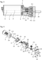
- the depictions in the 1 and 2 show a gear pump 1 with a delivery unit 2 for delivering a fluid and a drive unit 3 designed as an electric motor.
- the drive unit 3 is used to operate the delivery unit 2, which, via two connections 26 serving as inlet and outlet, from the fluid to be delivered, in which it can be drinking water, for example, can be flown through.
- the drive unit 3 is detachably connected to the conveyor unit 2 .
- the connecting elements 7, 8 are provided.
- the connecting elements 7, 8 are designed as locking elements and therefore allow a simple and error-free locking connection of the conveyor unit 2 and the drive unit 3.
- the latching elements 7, 8 face one another and act together in a latching manner in the manner of a bayonet connection 50, cf. 2 . Details of the bayonet connection 50 are based on the representations in the 9a to 14 be explained in more detail.
- the connecting elements 7 are arranged on an end face of the conveyor unit 2 and interact with the connecting elements 8 arranged on the drive unit 3 in a latching manner. While the connecting elements 7 are arranged directly on the conveyor unit 2 , the connecting elements 8 are arranged indirectly on the drive unit 3 via a disc-shaped intermediate element 6 .
- the indirect arrangement of the connecting elements 8 on the drive unit 3 has the advantage that the intermediate element 6 can be used as an adapter for connecting different drive units 3, e.g.
- connection elements 8 on the drive side can be arranged directly on the drive 3 .
- connecting elements 7 it would also be conceivable for the connecting elements 7 to be formed on an intermediate element, which is not shown in the figures and is connected to the conveyor unit 2 .
- While the representation in 1 shows a disconnected state, shows the representation in 2 the mounted gear pump 1, in which the drive unit 3 and the delivery unit 2 are detachably connected to one another via the bayonet connection 50 by mutual latching.
- the end faces of the conveyor unit 2 and the intermediate element 6 of the drive unit 3 lie flush and flat against one another and form a connection area 5.
- the drive unit 3 of the gear pump 1 has a substantially cylindrical geometry and is designed as an electric motor.
- the drive unit 3 has electrical connections 3.1. By energizing the drive unit 3, a drive shaft 3.2 is set in rotation, which is used to drive the conveyor unit 3.
- the drive unit 3 is a commercially available standard electric motor in a wide variety of designs, such as brushless or brushed electric motors of different power classes.
- an intermediate shaft 14 extending between the drive 3 and the conveyor unit 2 is provided.
- the intermediate shaft 14 is designed as a separate component in the exemplary embodiment.
- the intermediate shaft 14 is connected to a drive shaft 3.2, designed as a short stub axle, of the drive unit 3 and on the other side to the conveyor unit 3.
- the intermediate shaft 14 it would also be conceivable for the intermediate shaft 14 to be connected in one piece to the drive shaft 3.2. In this case, however, a standard motor could not be used.
- the intermediate shaft 14 has a shaft connection 14.2 for connection to the drive unit 3.
- the shaft connection 14.2 is cylindrical and sleeve-like and is an integral part of the intermediate shaft 14.
- the shaft connection 14.2 is pressed onto the drive shaft 3.2 for connection to the drive unit 3.
- the intermediate shaft 14 can in particular be made of stainless steel with a minimum chrome content of 16%, which is approved for use in the food sector or for driving gear pumps 1 for pumping drinking water.
- the drive shaft 3.2 of the drive unit 3 does not come into contact with the fluid to be pumped due to the intermediate shaft 14 pressed on in the manner of a shaft extension.
- the drive unit 3 On one end face, the drive unit 3 has a disc-shaped intermediate element 6 which is releasably attached to the drive unit 3 by means of fastening means 23 designed as screws and corresponding, corresponding bores 24 .
- the intermediate element 6 is essentially round.
- the intermediate element 6 has the drive-side connecting elements 8 which are recesses 8 .
- the intermediate element 6 has a shaft bearing 13 for supporting the intermediate shaft 14 .
- the shaft bearing 13 is designed in the manner of a cylindrical collar and extends in the center of the intermediate element 6 essentially perpendicularly to its surface.
- the conveyor unit 2 is essentially cuboid and has a housing 2.1 and a cover 2.2, which are connected to one another by means of cylindrical plug-in connection elements 22 shaped like dumbbells.
- the plug-in connection elements 22 are inserted into correspondingly designed recesses 33 for connection and overlap the planar contact area between the housing 2.1 and the cover 2.2 on its underside and upper side, see also FIG 4 and 9a .
- the cover 2.2 has two tubular connections 26 serving as inlet and outlet, via which the delivery unit 2 can be connected to other, not shown, components of the respective hydraulic system.
- the delivery unit 2 On the side opposite the connections 26, the delivery unit 2 has a flat fastening area B, on which the connecting elements 7 are formed in one piece.
- the connecting elements 7 are as shown in 1 designed as a bayonet hook.
- the bayonet hooks 7 are arranged directly on the fastening area B.
- these it is also conceivable for these to be arranged indirectly on the fastening area B via an intermediate element 6 .
- An inverse arrangement would also be conceivable, ie arranging the bayonet hooks 7 on the drive side and the recesses 8 on the conveying side.
- the housing 2.1 and the cover 2.2 of the conveyor unit 2 as well as the intermediate element 6 and all elements arranged on it are preferably made of plastic by means of suitable methods, in particular injection molding methods. All components that come into contact with the fluid to be pumped are suitable for use in the food and drinking water sectors.
- a gear space 35 is arranged inside the housing 2.1.
- the gear space 35 is sealed off from the cover 2.2 by means of a seal 25 designed as an O-ring.
- two gears 4.1 and 4.2 are rotatably arranged in the gear space 35 in the gear space 35.
- the teeth of the driven gear 4.1 engage in the corresponding gaps in a second co-rotating gear 4.2.
- the co-rotating gear 4.2 is rotatably mounted parallel to the axis of the driven gear 4.1 on an axle 21 arranged in the housing 2.2.
- Both gears 4.1, 4.2 are flowed around by the fluid to be pumped.
- a rotating movement of the driven gear wheel 4.1 causes the co-rotating gear wheel 4.2 to rotate in the opposite direction.
- connection 26 are connected to the inlet 31 and the outlet 32 and can be guided through the cover 2.2 or arranged on the lateral walls of the housing 2.1.
- the driven gear wheel 4.1 is plug-connected to the intermediate shaft 14 for driving the conveyor unit 2.
- the drive force is transmitted from the intermediate shaft 14 to the driven gear wheel 4.1 via corresponding actuating contours 14.1 and 16.1.
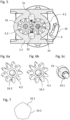
- the actuating contour 14.1 is designed as a pentagon, which is arranged as an outer contour on the end of the intermediate shaft 14 opposite the drive unit 3, cf. Figure 6c .
- the driven gear wheel 4.1 has a corresponding pentagonal contour, designed as an inner contour, as the actuating contour 16.1, cf. Figure 6b .
- the actuating contour 14.1 is inserted into the actuating contour 16.1 to drive the driven gear wheel 14.1.
- the design as a pentagon enables the torque to be transmitted effectively.
- the co-rotating gear wheel 4.2 has no actuating contour, but rather a bearing contour 16.2 designed as a round bore, cf. Figure 6a .
- the geometries of the actuating contour 14.1 and the bearing contour 16.2 are selected in such a way that the actuating contour 14.1 of the intermediate shaft 14 cannot be inserted into the bearing contour 16.2 of the co-rotating gear wheel 4.2, cf. 7 . This ensures that the intermediate shaft 14 can only be connected to the driven gear 4.1.
- the bearing contour 16.2 is designed in such a way that the co-rotating gear wheel 4.2 can only be connected to the corresponding axle 21 provided for this purpose, see also FIG Figure 8b .
- a shaft sealing ring 15 is provided to seal the intermediate shaft 14 from the gear space 35 arranged in the housing 2.1 of the delivery unit 2, cf. 4 .
- the shaft sealing ring 15 is designed as a radial shaft sealing ring.
- the intermediate shaft 14 has a corresponding coating in the area of the shaft sealing ring 15, or has been hardened to the corresponding hardness specification by means of Kolsterizing.
- the edges of the operating contour 14.1, which is designed as a pentagon are rounded.
- Figure 8b shows an enlargement of section VIII b according to FIG Figure 8a .
- the driven gear wheel 4.1 is slipped onto the actuating contour 14.1 of the intermediate shaft 14.
- a slide bearing 17 in the housing 2.1 of the conveyor unit is in the immediate vicinity of the gear wheel 4.1 2 arranged.
- the arrangement of the slide bearing 17 in the wall 2.3 of the conveyor unit 2 near the gear wheel 4.1 enables additional guidance of the intermediate shaft 14.
- the slide bearing 17 can be designed as a recess in the wall 2.3 if the wall is made of a suitable material.
- the plain bearing 17 can be used as a separate component in the wall 2.3 and be designed, for example, as a plain bearing bush.
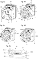
- the representation in Figure 9a shows the fastening area B arranged on one side of the conveyor unit 2.
- Four bayonet hooks 7 are arranged at a certain radial distance from the center point of the fastening area B.
- FIG. The bayonet hooks 7 are arranged point-symmetrically to a central round bore of the fastening area B at regular intervals, so that there is an angle of 90° between the bayonet hooks 7 in each case.
- the bayonet hooks 7 are formed in one piece with the housing 2.1. Based on the representation in 14 it can be seen that the bayonet hooks 7 are essentially L-shaped with a rectangular base area and have a base 7.1 and a latching part 7.2.
- the Base 7.1 extends perpendicularly from the surface of the attachment area B.
- the latching part 7.2 extends transversely to the base 7.1.
- the lower edge of the locking part 7.2 extends parallel to the surface of the fastening area B.
- the outer edges of the bayonet hook 7 are beveled or have chamfers, which can facilitate insertion into the corresponding recesses 8.
- the intermediate element 6 fastened to the drive unit 3 in the present exemplary embodiment is designed in the manner of a flat round disk, cf. Figure 9b .
- the intermediate element 6 has four continuous recesses 8 which are designed in the manner of circular ring segments 34 .
- the recesses 8 are designed in such a way that they can interact with the bayonet hooks 7 to connect the delivery unit 2 to the drive unit 3 .
- the recesses 8 are arranged point-symmetrically on a common circular path around a central round bore. The angular spacing of the recesses is accordingly 90°.
- the recesses 8 each have a plug-in area 8.1, cf. 10 .
- This plug-in area 8.1 is adapted to the geometry of the locking part 7.2 of the bayonet hook 7 and enables the bayonet hook 7 to be inserted .
- This securing area 8.2 is designed to interact with the latching part 7.2 of the bayonet hook 7. It extends flat and web-like from the outer radius of the recess 8 to about one third of its radial length, cf. 10 .
- the securing area 8.2 is arranged in the lower area of the recess 8; its thickness corresponds to approximately half the thickness of the intermediate element 6, cf. 12a .
- the recesses 8 have bevels for easy connection to the bayonet hooks 7 .
- the conveyor unit 2 and the drive unit 3 are configured such that they can be rotated relative to one another, with the axis of rotation D corresponding to the drive axis A, see also FIG 3 .
- the securing area 8.2 of the recess 8 and the latching part 7.2 of the bayonet hook 7 come into mutual engagement, cf. 12a .
- No additional tools are required to produce the bayonet connection 50 .
- the four bayonet hooks 7 grip behind the securing areas 8.2 of the recesses 8, as a result of which they are locked in a form-fitting manner.
- the bayonet connection 50 has a reverse rotation lock 10 for securing against reverse rotation.
- the anti-reverse device 10 serves to secure against undesired loosening due to vibrations or shocks during operation of the gear pump 1.
- the delivery unit 2 has a safety hook 10.1, cf. Figure 9a .
- the safety hook 10.1 is arranged radially on the outside of the fastening area B and is designed as a spring arm which is articulated on one side and is resilient in the radial direction.
- the safety hook 10.1 has a projecting safety lug 10.2, which extends essentially perpendicularly to the surface of the fastening area B at the free end of the safety hook 10.1.
- the securing lug 10.2 engages in a correspondingly designed recess 10.3 of the intermediate element 6, cf. Figures 9d and 9e .
- the safety hook 10.1 can be manually disengaged from the recess 10.3.
- a releasing force sufficient to release the bayonet connection 50 can be generated by mutually rotating the delivery unit 2 relative to the drive unit 3 .
- the reverse rotation lock 10 has a dual function. It not only serves to avoid unintentional loosening, but also shows a correctly latched bayonet connection 50 between the conveyor unit 2 and the drive unit 3 as a connection indicator 36 that can be read from the outside. Only when the bayonet connection 50 is correctly engaged are the securing lug 10.2 visible from the outside and the recess 10.3 engaged with one another.
- the intermediate element 6 has a total of four recesses 10.3, which are arranged at equal distances over the circumference of the intermediate element 6, cf. Fig. 9e .
- One securing lug 10.2 can engage in any of these recesses 10.3.
- the drive unit 3 can thus be connected to the conveyor unit 2 in any four orientations or assembly positions, which differ in the rotational position of the drive unit 3 about its drive axis A.
- the securing areas 8.2 each have a compensation ramp 9 for tolerance compensation.
- the compensating ramp 9 is designed in such a way that it can interact with the latching part 7.2 of the corresponding bayonet hook 7.
- the compensating ramp 9 is arranged in the circumferential direction over about two thirds of the length of the securing area 8.2 and essentially covers its entire width in the radial direction.
- the compensating ramp 9 is designed as an inclined plane that rises in the circumferential direction and, in the installed state, extends in the direction of the latching part 7.2 of the bayonet hook 7, see also FIG Figure 12b .
- the compensating ramp 9 can be used to compensate for tolerances and ensure a play-free connection between the conveyor unit 2 and the drive unit 3.
- the compensating ramp 9 is designed in such a way that it can be reversibly deformed if there is a tolerance overlap.
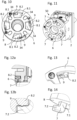
- FIGS. 15 to 20 show a second embodiment which, in contrast to the first embodiment, does not have a bayonet connection 50 but a snap hook connection 60, but otherwise corresponds to all relevant features of the first embodiment.
- the snap hook connection 60 differs from the bayonet connection 50 described above essentially in the structural design of the connecting elements 11, 12.
- the representation in 15 1 shows a fastening area B arranged on one side of the conveyor unit 2.
- Four recesses 12 are arranged at a certain radial distance from the center point of the fastening area B.
- FIG. The recesses 12 are arranged at equal intervals and tangentially to a central round bore of the fastening area B, so that there is an angle of 90° between the recesses 12 in each case.
- the recesses 12 are designed as essentially rectangular openings in the attachment area B, cf. 19 .
- the recesses 12 each have a latching area 12.1, which is arranged in the manner of an edge on the back of the fastening area B, see also FIG 20 .
- the fastening area B has four guide elements 20, which are arranged as rectangular recesses designed in the manner of notches on the edge of the central round bore.
- the guide elements 20 are aligned with the recesses 12.
- latching tongues 11 of the snap hook connection 60 are formed on an intermediate element 6, cf. 18 .
- the locking tongues 11 have a tab-like basic shape and extend essentially transversely to the surface of the intermediate element 6 in the same direction as the shaft bearing 13 designed as a cylindrical collar.
- the latching tongues 11 are designed to be resilient in the radial direction in the manner of a resilient cantilever.
- the four latching tongues 11 are arranged at a uniform distance from one another on the same radius, so that they are aligned with the recesses 12 of the conveyor unit 2 to produce a latching connection, cf. 16 .
- the latching tongues 11 In the region of their tip, the latching tongues 11 have a latching area 11.1, which is designed like an edge transversely to the tab-like base body of the latching tongue 11.
- the tip of the latching tongues 11 is provided with an insertion bevel 11.2, by means of which the insertion of the latching tongues 11 into the corresponding recesses 12 of the conveyor unit 2 can be facilitated.
- the intermediate element 6 has four guide elements 19 which are designed as rectangular, nose-like projections on the cylindrical collar of the shaft bearing 13 . The guide elements 19 are aligned with the latching tongues 11.
- the drive unit 3 is moved in the insertion direction R along the drive axis A toward the conveyor unit 2 and inserted into the recesses 12, cf. Figures 15 and 16 .
- the tips of the snap-in tongues 11 hit the edges of the corresponding recesses 12 in the area of the fastening area B.
- the resiliently designed snap-in tongues 11 spring in in the radial direction.
- the chamfers 11.2 facilitate insertion.
- the tip of the latching tongue 11 can have a suitable colored marking which is visible from the outside in the latched connection position and is designed as a connection indicator 36 .
- a marking can be arranged in an area between the insertion bevel 11.2 and the latching area 11.1. It can thus be recognized in a simple manner whether the snap hook connection 60 has been produced correctly. If the latching tongues 11 do not latch completely with the recesses 12, an edge of the recess 12 covers the colored marking, which means that the assembly personnel can identify an assembly error.
- the pump assemblies 100 each have a delivery unit 2 , a drive unit 3 connected thereto and one or more valve units 18 .
- the delivery unit 2 has at least two connecting elements 27 , 28 for the detachable connection of the delivery unit 2 to a valve unit 18 .
- the connecting elements 27, 28 can be arranged directly on the conveyor unit 2 or indirectly via an adapter-like intermediate element 37.
- the connecting elements 27, 28 are designed as bayonet hooks and corresponding recesses in the exemplary embodiment shown and arranged laterally on the delivery unit 2 so that the valve unit 18 can be connected to the drive unit 3 in a direction transverse to the drive unit 3 by means of a bayonet connection 70 .
- the housing of the drive unit 3 and the valve housing of the valve units 18 can move in the same direction (cf. 21 ) or in the opposite direction (cf. 22 ), or perpendicular to each other (cf. 23 ) extend.
- the connecting elements for connecting the delivery unit 2 to the valve unit 18 can also be designed as latching tongues and corresponding recesses for producing a snap hook connection.
- the bayonet connection 70 and the snap hook connection can be designed in accordance with the latching connections between the conveyor unit 2 and the drive unit 3 described above.
- valve units 18 can also be connected to one another by means of corresponding connecting elements 29, 30, cf. 23 . In this way, series arrangements of valves can be produced to carry out various switching operations. Alternatively, the valve units 18 can be connected to one another via intermediate elements 37 .
- the connecting elements 29, 30 of the valve units 18 are designed as latching elements and can be designed in particular as bayonet hooks and corresponding recesses or as latching tongues and corresponding recesses.
- the connecting elements 27, 28, 29, 30 are preferably designed to correspond to the connecting elements 7, 8, 11, 12 of the conveyor unit 2 or the drive unit 3.
- the drive unit 3 is moved axially aligned in the insertion direction R along the drive axis A toward the delivery unit 2 , with the intermediate shaft 14 engaging in a corresponding round bore of the fastening area B. Furthermore, the bayonet hooks 7 engage in the plug-in areas 8.1 of the respective recesses 8, cf. 9c . As soon as the intermediate element 6 and the conveyor unit 2 lie flat against one another, the drive unit 3 and thus the intermediate element 6 are rotated clockwise relative to the conveyor unit 2 . The latching parts 7.2 of the bayonet hooks 7 latch with the securing areas 8.2 of the respective recesses.
- the safety lug 10.2 of a reverse rotation safety device 10 snaps into a corresponding safety recess 10.3 of the intermediate element 6, cf. Fig. 9e .
- tolerances are compensated for when the conveyor unit 2 and the drive unit 3 rotate relative to one another by the compensation ramps 9, which can deform to compensate for tolerances, cf. Figure 12b .
- the drive unit 3 is moved in the plug-in direction R along the drive axis A towards the delivery unit 2 , with the intermediate shaft 14 engaging in a corresponding round bore of the fastening area B. Furthermore, the locking tongues 12 engage with their tips in the recesses 11, cf. 17 . With further insertion, the insertion bevels 11.2 of the latching tongues 11 come into contact with the edges of the recesses 12, as a result of which the latching tongues 11 deflect radially inwards with further axial displacement. When the connection position is reached, the latching tongues 11 spring out automatically and the latching area 11.2 of the latching tongues 11 latches with the latching area 12.1 of the respective recess 12, cf. 20 .
- Such a snap hook connection 60 between conveyor unit 2 and drive unit 3 is released by applying a releasing force counter to the insertion direction R. This allows the latching areas 11.2 of the latching tongues 11 to disengage from the latching areas 12.1 of the recesses 12 and the connection to be released.
- the gear pump 1 described above, the pump assembly 100 and the method for connecting the delivery unit 2 and the drive unit 3 of a gear pump 1 are characterized by a simple and fault-prone connection of the drive unit 3 with the conveyor unit 2, which can also be carried out safely by inexperienced assembly personnel.
Abstract
Die Erfindung betrifft eine Zahnradpumpe (1) zum Fördern eines Fluids mit einer mindestens zwei Zahnräder (4.1, 4.2) aufweisenden Fördereinheit (2) und einer die Zahnräder (4.1, 4.2) antreibenden Antriebseinheit (3), die über werkzeuglos betätigbare Verbindungselemente (7, 8, 11, 12) lösbar miteinander verbunden sind, wobei die Verbindungselemente (7, 8, 11, 12) als Rastelemente ausgebildet sind. Einen weiteren Gegenstand der Erfindung bildet eine Pumpanordnung (100) mit einer derartigen Zahnradpumpe (1) und mindestens einer Ventileinheit (18). Einen weiteren Gegenstand der Erfindung bildet eine Pumpanordnung (100) mit einer derartigen Zahnradpumpe (1) und mindestens einer Ventileinheit (18). Einen weiteren Gegenstand der Erfindung bildet ein Verfahren zum lösbaren Verbinden einer Fördereinheit (2) und einer Antriebseinheit (3) einer Zahnradpumpe (1) über werkzeuglos betätigbare Verbindungselemente.The invention relates to a gear pump (1) for delivering a fluid, with a delivery unit (2) having at least two gears (4.1, 4.2) and a drive unit (3) which drives the gears (4.1, 4.2) and which can be actuated without tools via connecting elements (7, 8, 11, 12) are detachably connected to one another, the connecting elements (7, 8, 11, 12) being designed as latching elements. A further object of the invention is a pump arrangement (100) with such a gear pump (1) and at least one valve unit (18). A further object of the invention is a pump arrangement (100) with such a gear pump (1) and at least one valve unit (18). Another object of the invention is a method for detachably connecting a delivery unit (2) and a drive unit (3) of a gear pump (1) via connecting elements that can be actuated without tools.
Description
Die Erfindung betrifft eine Zahnradpumpe zum Fördern eines Fluids mit einer mindestens zwei Zahnräder aufweisenden Fördereinheit und einer die Zahnräder antreibenden Antriebseinheit, die über werkzeuglos betätigbare Verbindungselemente lösbar miteinander verbunden sind. Weitere Gegenstände der Erfindung bilden eine Pumpanordnung mit einer solchen Zahnradpumpe und mindestens einer Ventileinheit sowie ein Verfahren zum werkzeuglosen, lösbaren Verbinden der Fördereinheit und der Antriebseinheit einer solchen Zahnradpumpe.The invention relates to a gear pump for delivering a fluid, having a delivery unit having at least two gears and a drive unit driving the gears, which are detachably connected to one another via connecting elements that can be actuated without tools. Further objects of the invention are a pump arrangement with such a gear pump and at least one valve unit as well as a method for tool-free, detachable connection of the delivery unit and the drive unit of such a gear pump.
Zahnradpumpen dieser Art werden in verschiedenen Bereichen der Technik dazu verwendet, Fluide, insbesondere Flüssigkeiten, zu fördern, bspw. in Getränkeautomaten oder anderen Systemen der Lebensmittelindustrie.Gear pumps of this type are used in various areas of technology to convey fluids, in particular liquids, for example in vending machines or other systems in the food industry.
Eine Zahnradpumpe weist in der Regel eine Fördereinheit mit zwei Zahnrädern auf. Das zu fördernde Fluid wird über die Zähne der im gegenseitigen Eingriff stehenden, entlang der Förderrichtung ein Druckgefälle erzeugenden Zahnräder gefördert. Zum Antrieb der Zahnräder dient eine mit der Fördereinheit verbundene Antriebseinheit, welche häufig als Elektromotor ausgebildet ist. Über die Antriebseinheit wird in der Regel ein Zahnrad direkt angetrieben und das andere aufgrund der in gegenseitigem Eingriff stehenden Zähne indirekt. Oftmals sind die Fördereinheit und die Antriebseinheit über werkzeuglos betätigbare Verbindungselemente miteinander verbunden, was eine schnelle Montage und Demontage solcher Zahnradpumpen oder auch den Austausch einzelner Komponenten wie etwa der Antriebseinheit ermöglicht.A gear pump usually has a delivery unit with two gears. The fluid to be conveyed is conveyed via the teeth of the gear wheels which are in mutual engagement and generate a pressure gradient along the conveying direction. A drive unit, which is connected to the conveyor unit and is often designed as an electric motor, is used to drive the gear wheels. The drive unit usually drives one gear directly and the other indirectly because of the meshing teeth. The delivery unit and the drive unit are often connected to one another via connecting elements that can be actuated without tools, which enables such gear pumps to be assembled and disassembled quickly or individual components such as the drive unit to be exchanged.
Aus der
In der Praxis hat sich bei solchen Zahnradpumpen die Verwendung von separaten, schellenartigen Spannringen als nachteilig herausgestellt, da die Verwendung solcher Spannringe mit einem aufwändigen, mehrere Schritte erfordernden Montageprozess verbunden ist. Überdies ist die Herstellung der Verbindung über solche Spannringe in gewissem Maße auch von dem Geschick des Monteurs abhängig. Denn infolge etwa einer fehlerhaften Positionierung oder einer zu geringen Spannkraft können Montagefehler auftreten, welche den Betrieb der Zahnradpumpe beeinträchtigen oder sogar zu einem Ausfall der Zahnradpumpe führen können.In practice, the use of separate, clamp-like clamping rings has proven to be disadvantageous in such gear pumps, since the use of such clamping rings is associated with a complex assembly process that requires several steps. Furthermore, the production of the connection via such clamping rings also depends to a certain extent on the skill of the fitter. This is because, as a result of incorrect positioning or insufficient clamping force, assembly errors can occur which can impair the operation of the gear pump or even lead to the gear pump failing.
Davon ausgehend stellt sich der Erfindung die Aufgabe, eine Zahnradpumpe, eine Pumpanordnung sowie ein Verfahren anzugeben, welche sich dadurch auszeichnen, dass die Förder- und Antriebseinheit der entsprechenden Zahnradpumpen auf einfache und fehlerunanfällige Art und Weise miteinander verbunden werden können.Proceeding from this, the object of the invention is to specify a gear pump, a pump arrangement and a method which are characterized in that the delivery and drive unit of the corresponding gear pumps can be connected to one another in a simple and error-free manner.
Diese Aufgabe wird bei einer Zahnradpumpe der eingangs genannten Art durch die Merkmale des Patentanspruchs 1 gelöst. Vorteilhafte Weiterbildungen sind in den abhängigen Unteransprüchen angegeben.In a gear pump of the type mentioned at the outset, this object is achieved by the features of
Aufgrund der Ausgestaltung der Verbindungselemente als Rastelemente ergibt sich eine einfache und fehlerunanfällige Verbindung der Antriebseinheit mit der Fördereinheit. Die Rastelemente erlauben auf bedienerfreundliche Art und Weise eine genaue und auch nach mehrfachem Lösen wiederholgenaue Montage mit konstanter Verbindungskraft, welche auch für ungeübtes Montagepersonal sicher durchführbar ist. Montagefehler, welche sich bspw. durch eine fehlerhafte Positionierung der Verbindungselemente oder eine unzureichende Verbindungskraft ergeben könnten, werden vermieden.Due to the design of the connecting elements as latching elements, the drive unit is connected to the conveyor unit in a simple and error-free manner. In a user-friendly manner, the locking elements allow precise and repeatable assembly with a constant connection force, even after multiple loosening assembly personnel can be carried out safely. Assembly errors, which could result, for example, from incorrect positioning of the connecting elements or insufficient connecting force, are avoided.
In vorteilhafter Ausgestaltung wird vorgeschlagen, dass Verbindungselemente an der Fördereinheit und Verbindungselemente an der Antriebseinheit angeordnet und korrespondierend zueinander ausgebildet sind. Eine solche Anordnung ermöglicht eine besonders einfache und bedienerfreundliche Verbindung bzw. Verriegelung der Antriebseinheit mit der Fördereinheit. Besonders vorteilhaft ist es, wenn jeweils die gleiche Anzahl an Verbindungselementen an der Fördereinheit und der Antriebseinheit ausgebildet ist. Ferner ist es von Vorteil, wenn die Verbindungselemente an der Fördereinheit und an der Antriebseinheit bezüglich ihrer jeweiligen Geometrie korrespondierend ausgebildet sind. Darüber hinaus hat es sich als vorteilhaft erwiesen, wenn die Verbindungselemente bezüglich ihrer jeweiligen Position an der Fördereinheit und der Antriebseinheit korrespondierend ausgebildet sind, wodurch sich eine besonders einfache Möglichkeit der Verbindung der Antriebseinheit mit der Fördereinheit ergeben kann. Die Verbindungselemente können direkt an der Fördereinheit und/oder der Antriebseinheit angeordnet sein. Alternativ können die Verbindungselemente auch indirekt über ein Zwischenelement an der Fördereinheit und/oder der Antriebseinheit angeordnet sein. Dem Zwischenelement kann optional auch eine Adapterfunktion beispielsweise zur Anordnung unterschiedlicher Antriebseinheiten an ein und der selben Fördereinheit zukommen.In an advantageous embodiment, it is proposed that connecting elements are arranged on the conveyor unit and connecting elements on the drive unit and are designed to correspond to one another. Such an arrangement enables a particularly simple and user-friendly connection or locking of the drive unit to the conveyor unit. It is particularly advantageous if the same number of connecting elements is formed on the conveyor unit and the drive unit. Furthermore, it is advantageous if the connecting elements on the conveyor unit and on the drive unit are designed to correspond in terms of their respective geometry. In addition, it has proven to be advantageous if the connecting elements are designed to correspond with respect to their respective position on the conveyor unit and the drive unit, which can result in a particularly simple possibility of connecting the drive unit to the conveyor unit. The connecting elements can be arranged directly on the conveyor unit and/or the drive unit. Alternatively, the connecting elements can also be arranged indirectly via an intermediate element on the conveyor unit and/or the drive unit. The intermediate element can optionally also have an adapter function, for example for arranging different drive units on one and the same conveyor unit.
In diesem Zusammenhang hat es sich als besonders vorteilhaft herausgestellt, wenn die Verbindungselemente an einander zugewandten Seiten der Fördereinheit und der Antriebseinheit ausgebildet sind. In diesem Zusammenhang kann es auch sinnvoll sein, dass Verbindungselemente an mehreren Seiten der Förder- und/oder Antriebseinheit angeordnet sind. Dies erhöht die Flexibilität im Hinblick auf die Verbindung von Fördereinheit und Antriebseinheit mit unterschiedlichen Ausrichtungen zueinander.In this context, it has proven to be particularly advantageous if the connecting elements are formed on sides of the conveyor unit and the drive unit that face one another. In this context, it can also be useful for connecting elements to be arranged on several sides of the conveyor and/or drive unit. This increases the flexibility with regard to the connection of the conveyor unit and drive unit with different alignments to each other.
Eine vorteilhafte Ausgestaltung sieht vor, dass Verbindungselemente an ebenen Befestigungsbereichen der Fördereinheit und/oder der Antriebseinheit ausgebildet sind. Nach Verrasten der Rastelemente ergibt sich eine flächige Anlage und damit eine zuverlässige Verbindung.An advantageous embodiment provides that connecting elements are formed on flat fastening areas of the conveyor unit and/or the drive unit. After locking the locking elements, there is a flat contact and thus a reliable connection.
Des Weiteren hat es sich als vorteilhaft herausgestellt, wenn die Verbindungselemente in gleichmäßigen Abständen, insbesondere Winkelabständen, relativ zueinander angeordnet sind. Eine solche Anordnung erlaubt eine einfache Verbindung der Fördereinheit und der Antriebseinheit miteinander und ist darüber hinaus vorteilhaft im Hinblick auf eine gleichmäßige Übertragung von Kräften zwischen der Fördereinheit und der Antriebseinheit. Hierdurch kann eine qualitativ besonders hochwertige und feste Verbindung zwischen der Fördereinheit und der Antriebseinheit erreicht werden. In diesem Zusammenhang ist es besonders bevorzugt, wenn die Verbindungselemente in gleichmäßigen Abständen in Umfangsrichtung relativ zueinander angeordnet sind, wodurch eine besonders gleichmäßige Verbindungskraft erzeugt werden kann.Furthermore, it has proven to be advantageous if the connecting elements are arranged at equal distances, in particular angular distances, relative to one another. Such an arrangement allows the conveyor unit and the drive unit to be connected to one another in a simple manner and is also advantageous with regard to a uniform transmission of forces between the conveyor unit and the drive unit. As a result, a particularly high-quality and firm connection can be achieved between the conveyor unit and the drive unit. In this context, it is particularly preferred if the connecting elements are arranged at equal intervals relative to one another in the circumferential direction, as a result of which a particularly uniform connecting force can be generated.
Es wird ferner vorgeschlagen, dass die Verbindungselemente einstückig mit der Fördereinheit und/oder der Antriebseinheit ausgebildet sind. Eine derartige Anordnung ist besonders vorteilhaft im Hinblick auf eine einfache Verbindung, da die Verbindungselemente verliersicher ausgestaltet sind. Ferner ist eine derartige Ausführung vorteilhaft im Hinblick auf die Fertigung der Fördereinheit und/oder der Antriebseinheit, bspw. mittels Spritzgussverfahren, da die Verbindungselemente direkt bei der Herstellung der Fördereinheit und/oder der Antriebseinheit mit ausgebildet werden können.It is also proposed that the connecting elements are designed in one piece with the conveyor unit and/or the drive unit. Such an arrangement is particularly advantageous with regard to a simple connection, since the connecting elements are designed to be captive. Furthermore, such an embodiment is advantageous with regard to the production of the conveyor unit and/or the drive unit, for example by means of injection molding processes, since the connecting elements can be formed directly during the production of the conveyor unit and/or the drive unit.
In einer vorteilhaften Weiterbildung der Erfindung wird vorgeschlagen, dass die Fördereinheit und die Antriebseinheit in mehreren Montagestellungen miteinander verbindbar sind. Eine derartige Ausgestaltung ermöglicht eine einfache, bedienerfreundliche Verbindung der Fördereinheit mit der Antriebseinheit, da die Fördereinheit und die Antriebeinheit nicht nur in einer, sondern in mehreren Montagestellungen bzw. Ausrichtungen miteinander verbindbar sind. Als vorteilhaft hat es sich ferner herausgestellt, wenn sich die Montagestellungen bezüglich der rotatorischen Ausrichtung der Fördereinheit relativ zur Antriebseinheit unterscheiden.In an advantageous development of the invention, it is proposed that the conveyor unit and the drive unit can be connected to one another in a number of assembly positions. Such a configuration enables a simple, user-friendly connection of the conveyor unit to the drive unit, since the conveyor unit and the drive unit can be connected to one another not just in one but in a number of assembly positions or orientations. It has also proven to be advantageous if the assembly positions differ with regard to the rotational alignment of the conveyor unit relative to the drive unit.
Eine weitere vorteilhafte Ausgestaltung sieht vor, dass die Anzahl der möglichen Montagestellungen der Anzahl der korrespondierenden Verbindungselemente entspricht. Eine erhöhte Anzahl an Montagestellungen kann Vorteile bieten bezüglich der Anordnung der Förder- und Antriebseinheit. Insbesondere kann in bestimmten Einbausituationen die Zugänglichkeit zu bestimmten Bereichen der Fördereinheit und/oder der Antriebseinheit verbessert werden. Vorteilhafterweise können bei zwei Paaren von Verbindungselementen zwei mögliche Montagestellungen vorgesehen sein. Ferner können bei drei Verbindungselementpaaren drei mögliche Montagestellungen vorgesehen sein, usw. Besonders bevorzugt ist es, wenn bei vier Paaren von Verbindungselementen vier Montagestellungen vorgesehen und auswählbar sind. Eine derartige Ausgestaltung ermöglicht eine schnelle und bedienerfreundliche Verbindung der Antriebseinheit mit der Fördereinheit, da bereits anhand der Anzahl der Verbindungselementpaare festgestellt werden kann, wie viele mögliche Montagestellungen vorliegen.A further advantageous embodiment provides that the number of possible assembly positions corresponds to the number of corresponding connecting elements. An increased number of assembly positions can offer advantages with regard to the arrangement of the conveyor and drive unit. In particular, the accessibility to certain areas of the delivery unit and/or the drive unit can be improved in certain installation situations. Advantageously, two possible assembly positions can be provided for two pairs of connecting elements. Furthermore, with three pairs of connecting elements, three possible mounting positions can be provided, etc. It is particularly preferred if four mounting positions are provided and selectable with four pairs of connecting elements. Such an embodiment enables a quick and user-friendly connection of the drive unit to the conveyor unit, since it can already be determined from the number of pairs of connecting elements how many possible assembly positions there are.
In einer vorteilhaften Weiterbildung der Erfindung wird vorgeschlagen, dass die Verbindungselemente eine Bajonettverbindung bilden. Eine derartige Bajonettverbindung ist besonders vorteilhaft im Hinblick auf eine einfache und fehlerunanfällige Rastverbindung der Antriebseinheit mit der Fördereinheit. Ferner kann eine Bajonettverbindung eine für das Montagepersonal intuitive, wiederholgenaue, zerstörungsfrei lösbare Rastverbindung der Antriebseinheit mit der Fördereinheit ermöglichen. Die Herstellung einer Verbindung über eine Bajonettverbindung kann auch für ungeübtes Montagepersonal einfach und fehlerunanfällig durchführbar sein.In an advantageous development of the invention, it is proposed that the connecting elements form a bayonet connection. Such a bayonet connection is particularly advantageous with regard to a simple and error-free latching connection of the drive unit to the conveyor unit. Furthermore, a bayonet connection can be used by the assembly personnel enable intuitive, repeatable, non-destructively releasable locking connection of the drive unit with the conveyor unit. Establishing a connection via a bayonet connection can also be carried out easily and without error, even for inexperienced assembly personnel.
In diesem Zusammenhang wird vorgeschlagen, dass die Verbindungselemente als Bajonetthaken und/oder korrespondierende Ausnehmungen ausgebildet sind. Eine solche Ausgestaltung ermöglicht eine einfache Herstellung einer Bajonettverbindung. Insbesondere ist es vorteilhaft, wenn die Bajonetthaken zum Eingriff in die korrespondierenden Ausnehmungen ausgebildet sind. In diesem Zusammenhang kann es vorteilhaft sein, wenn die geometrischen Ausgestaltungen der Bajonetthaken und/oder der Ausnehmungen aufeinander angepasst sind bzw. korrespondierend gestaltet sind.In this context, it is proposed that the connecting elements are designed as bayonet hooks and/or corresponding recesses. Such an embodiment enables a bayonet connection to be produced in a simple manner. In particular, it is advantageous if the bayonet hooks are designed to engage in the corresponding recesses. In this context, it can be advantageous if the geometric configurations of the bayonet hooks and/or the recesses are adapted to one another or are designed to correspond.
In diesem Zusammenhang wird ferner vorgeschlagen, dass die Bajonetthaken eine im Wesentlichen rechtwinklige Form mit einem Sockel und einem sich rechtwinklig von dem Sockel abspreizenden Rastteil aufweisen. Eine derartige Anordnung erlaubt eine einfache und montagefreundliche Verbindung mittels der Bajonettverbindung. Darüber hinaus kann das sich rechtwinklig von dem Sockel abspreizende Rastteil auf einfache Art und Weise zur Erzeugung einer hochwertigen, formschlüssigen Rastverbindung verwendet werden. Alternativ zu der rechtwinkligen Abspreizung können auch Querabspreizungen des Rastteils von dem Sockel in einem Winkelbereich von 80° bis 100° zum Sockel vorgesehen sein.In this context, it is also proposed that the bayonet hooks have an essentially rectangular shape with a base and a latching part that spreads out from the base at right angles. Such an arrangement allows a simple and assembly-friendly connection by means of the bayonet connection. In addition, the latching part that spreads out at right angles from the base can be used in a simple manner to produce a high-quality, form-fitting latching connection. As an alternative to the right-angled spread, transverse spreads of the latching part from the base can also be provided in an angular range of 80° to 100° to the base.
In diesem Zusammenhang hat es sich als konstruktiv vorteilhaft erwiesen, wenn das Rastteil nach radial außen oder radial innen weist.In this context, it has proven to be structurally advantageous if the latching part points radially outwards or radially inwards.
Es hat sich ferner als konstruktiv vorteilhaft erwiesen, wenn die Ausnehmungen einen Steckbereich zum Einstecken der Bajonetthaken und einen Sicherungsbereich zum Verrasten der Bajonetthaken aufweisen.It has also proven to be structurally advantageous if the recesses have an insertion area for inserting the bayonet hooks and a securing area for latching the bayonet hooks.
In diesem Zusammenhang wird ferner vorgeschlagen, dass der Sicherungsbereich zum Verrasten mit dem Rastteil des Bajonetthakens zusammenwirkend gestaltet ist. Eine derartige Ausgestaltung ermöglicht eine bedienerfreundliche und auch bei mehrfachem Lösen zuverlässige Verbindung zwischen Antriebeinheit und Fördereinheit mittels einer Bajonettverbindung.In this context, it is also proposed that the securing area for latching be designed to interact with the latching part of the bayonet hook. Such an embodiment enables a user-friendly connection between the drive unit and the delivery unit, which is reliable even if it is released several times, by means of a bayonet connection.
In einer konstruktiv vorteilhaften Ausgestaltung sind die Ausnehmungen als Kreisringsegmente ausbildet, wobei sich die Steckbereiche über die eine Hälfte der Kreisringsegmente erstrecken und die Sicherungsbereiche in der anderen Hälfte der Kreisringsegmente angeordnet sind. Es ist bevorzugt, wenn die Geometrie der Steckbereiche mit der Geometrie der Bajonetthaken, und insbesondere des Rastteils der Bajonetthaken, korrespondierend ausgestaltet ist. Ferner kann eine derartige Anordnung vorteilhaft sein im Hinblick auf eine bedienerfreundliche Montage von Fördereinheit und Antriebseinheit. Die Herstellung einer Bajonettverbindung kann auf vorteilhafte Art und Weise durch sequenzielles Einstecken der Bajonetthaken in den Steckbereich der Ausnehmungen und anschließendes relatives Verdrehen der Bajonetthaken zu den Ausnehmungen ermöglicht werden. Hierdurch kann das Rastteil der Bajonetthaken mit dem Sicherungsbereich der Ausnehmungen formschlüssig verrastet werden. Alternativ zu einer Erstreckung über eine Hälfte der Kreisringsegmente können auch Erstreckungen über einen Anteil zwischen 30 % und 70 % und insbesondere 40 % und 60 % der Breite der Kreisringsegmente vorgesehen sein. In diesem Zusammenhang sind, angepasst auf die Anforderungen der Verbindung zwischen Förder- und Antriebseinheit, auch andere geometrische Verhältnisse, insbesondere breitere oder auch weniger breite Steckbereiche denkbar.In a structurally advantageous embodiment, the recesses are designed as circular ring segments, with the plug-in areas extending over one half of the circular ring segments and the securing areas being arranged in the other half of the circular ring segments. It is preferred if the geometry of the plug-in areas is designed to correspond to the geometry of the bayonet hooks, and in particular the locking part of the bayonet hooks. Furthermore, such an arrangement can be advantageous with regard to user-friendly assembly of the conveyor unit and drive unit. The production of a bayonet connection can be made possible in an advantageous manner by sequentially inserting the bayonet hooks into the insertion area of the recesses and then rotating the bayonet hooks relative to the recesses. As a result, the locking part of the bayonet hook can be locked in a form-fitting manner with the securing area of the recesses. As an alternative to an extension over half of the circular ring segments, extensions over a proportion of between 30% and 70% and in particular 40% and 60% of the width of the circular ring segments can also be provided. In this context, adapted to the requirements of the connection between the conveyor unit and the drive unit, other geometric relationships, in particular wider or also less wide plug-in areas, are also conceivable.
In diesem Zusammenhang wird ferner vorgeschlagen, dass sich die Sicherungsbereiche eben und stegartig vom Außenradius der Kreisringsegmente in radialer Richtung über mindestens ein Drittel der Ausdehnung der Kreisringsegmente erstrecken. Alternativ zu einer Erstreckung über ein Drittel der radialen Ausdehnung können auch Erstreckungen der Sicherungsbereiche von 10 % bis 50 % und insbesondere 25 % bis 45 % der radialen Ausdehnung der Kreisringsegmente vorgesehen sein.In this context, it is also proposed that the securing areas extend in a flat and web-like manner from the outer radius of the circular ring segments in the radial direction over at least one third of the extent of the circular ring segments extend. As an alternative to extending over a third of the radial extent, the securing areas can also extend by 10% to 50% and in particular 25% to 45% of the radial extent of the circular ring segments.
In einer Weiterbildung der Erfindung wird vorgeschlagen, dass die Sicherungsbereiche eine Ausgleichsrampe zum Toleranzausgleich aufweisen, welche mit den Rastteilen der jeweiligen Bajonetthaken zusammenwirkend gestaltet ist. Eine derartige Ausgestaltung ermöglicht auf einfache und vorteilhafte Art und Weise einen Ausgleich von Toleranzen und eine spielfreie Rastverbindung der Fördereinheit mit der Antriebseinheit. Bevorzugt ist die Ausgleichsrampe derart ausgebildet, dass sie sich bei Toleranzüberschneidung reversibel verformen kann.In a development of the invention, it is proposed that the securing areas have a compensating ramp for tolerance compensation, which is designed to interact with the latching parts of the respective bayonet hooks. Such an embodiment enables tolerances to be compensated for and a play-free locking connection of the conveyor unit with the drive unit in a simple and advantageous manner. The compensating ramp is preferably designed in such a way that it can be reversibly deformed when tolerances overlap.
In diesem Zusammenhang ist es ferner bevorzugt, wenn die Ausgleichsrampe als eine in Umfangsrichtung des Kreisringsegments ansteigende schiefe Ebene auf dem Sicherungsbereich angeordnet ist, welche sich insbesondere über mindestens zwei Drittel der Länge des Sicherungsbereichs erstreckt. Eine solche Ausgestaltung der Ausgleichsrampe ermöglicht einen einfachen und bedienerfreundlichen Toleranzausgleich. Je nach relativer Position des Rastteils des Bajonetthakens zu der Ausgleichsrampe des Sicherungsbereichs können unterschiedlich große Toleranzen ausgeglichen werden. Die schiefe Ebene kann dabei einen konstanten oder einen über die Länge der Ausgleichsrampe variierenden Anstiegswinkel aufweisen. Die einzelnen Sicherungsbereiche können gleich ausgestaltete Ausgleichsrampen aufweisen.In this context, it is also preferred if the compensating ramp is arranged on the securing area as an inclined plane rising in the circumferential direction of the circular ring segment, which extends in particular over at least two thirds of the length of the securing area. Such a configuration of the compensating ramp enables a simple and user-friendly tolerance compensation. Depending on the relative position of the locking part of the bayonet hook to the compensation ramp of the security area, different tolerances can be compensated. The inclined plane can have a constant angle of rise or one that varies over the length of the compensating ramp. The individual security areas can have compensating ramps of the same design.
Es wird ferner vorgeschlagen, dass die Antriebseinheit und die Fördereinheit zum Fixieren oder Lösen der Bajonettverbindung um eine Drehachse gegeneinander verdrehbar ausgebildet sind. Auf vorteilhafte Art und Weise können die Antriebseinheit und die Fördereinheit zunächst in axialer Richtung entlang der Drehachse im Bereich der Verbindungselemente ineinandergesteckt und in einem zweiten Schritt relativ zueinander um eine Drehachse gegeneinander verdreht werden. Dies erlaubt eine einfache und auch für ungeübtes Bedienpersonal schnell und sicher herstellbare Rastverbindung der Antriebseinheit mit der Fördereinheit. Ferner kann eine solche Verbindung auf einfache Art und Weise zerstörungsfrei gelöst werden, indem die zur Verbindung durchgeführten Verfahrensschritte umgekehrt werden.It is further proposed that the drive unit and the conveyor unit are designed to be rotatable in relation to one another about an axis of rotation in order to fix or release the bayonet connection. In an advantageous manner, the drive unit and the delivery unit can initially be plugged into one another in the axial direction along the axis of rotation in the area of the connecting elements and in a second step are rotated relative to each other about an axis of rotation against each other. This allows a snap-in connection of the drive unit to the conveyor unit that can be established quickly and reliably even by inexperienced operating personnel. Furthermore, such a connection can be broken in a simple manner in a non-destructive manner by reversing the process steps carried out for the connection.
In diesem Zusammenhang wird weiter vorgeschlagen, dass die Drehachse der Antriebsachse der Antriebseinheit entspricht. Hierdurch wird ein achssymmetrischer Aufbau ermöglicht, wobei die Antriebseinheit und/oder die Fördereinheit zur Verbindung um die Antriebsachse verdreht werden können. Vorteilhafter Weise kann das Verbinden durch eine Drehung in eine Drehrichtung und das Lösen der Verbindung durch eine Drehung in die entgegengesetzte Drehrichtung erfolgen.In this context, it is further proposed that the axis of rotation corresponds to the drive axis of the drive unit. This enables an axially symmetrical structure, in which case the drive unit and/or the conveyor unit can be rotated about the drive axis for connection. Advantageously, the connection can be made by turning in one direction of rotation and the connection can be released by turning in the opposite direction of rotation.
In einer Weiterbildung der Erfindung wird vorgeschlagen, dass die Fördereinheit mindestens zwei Bajonetthaken und die Antriebseinheit mindestens zwei korrespondierende Ausnehmungen zum Eingriff der Bajonetthaken aufweist. Eine derartige Anordnung ist vorteilhaft im Hinblick auf eine einfache und bezüglich der Verbindungskraft gleichmäßige Verbindung zwischen Fördereinheit und Antriebseinheit. In diesem Zusammenhang kann es alternativ auch vorteilhaft sein, dass die Fördereinheit mindestens zwei Ausnehmungen und die Antriebseinheit mindestens zwei korrespondierende Bajonetthaken aufweist.In a development of the invention, it is proposed that the conveyor unit has at least two bayonet hooks and the drive unit has at least two corresponding recesses for engaging the bayonet hooks. Such an arrangement is advantageous with regard to a simple connection between the delivery unit and the drive unit which is uniform in terms of the connection force. In this context, it can alternatively also be advantageous that the conveyor unit has at least two recesses and the drive unit has at least two corresponding bayonet hooks.
In einer Weiterbildung der Erfindung wird vorgeschlagen, dass die Fördereinheit mindestens drei, vier oder fünf Bajonetthaken zur Verbindung mit mindestens drei, vier oder fünf korrespondierenden, an der Antriebseinheit angeordneten Ausnehmungen aufweist. In diesem Zusammenhang ist es von besonderem Vorteil, wenn die Bajonetthaken und die korrespondierenden Ausnehmungen kreisförmig und gleichmäßig über den Umfang angeordnet sind. Es ist ferner ohne Weiteres denkbar, dass die Fördereinheit mindestens drei, vier oder fünf Ausnehmungen aufweist und die Antriebseinheit mindestens drei, vier oder fünf Bajonetthaken zum Eingriff in die Ausnehmungen aufweist. Eine größere Anzahl an korrespondierenden Bajonetthaken und Ausnehmungen hat sich als vorteilhaft im Hinblick auf die mechanische Belastbarkeit der Verbindung herausgestellt.In a development of the invention, it is proposed that the conveyor unit has at least three, four or five bayonet hooks for connection to at least three, four or five corresponding recesses arranged on the drive unit. In this connection it is of particular advantage if the bayonet hook and the corresponding Recesses are arranged in a circle and evenly over the circumference. It is also easily conceivable that the conveyor unit has at least three, four or five recesses and the drive unit has at least three, four or five bayonet hooks for engaging in the recesses. A larger number of corresponding bayonet hooks and recesses has proven to be advantageous with regard to the mechanical strength of the connection.
In einer Weiterbildung der Erfindung wird ferner vorgeschlagen, dass die Bajonettverbindung eine Rückdrehsicherung aufweist. Eine derartige Ausgestaltung ist vorteilhaft zur Sicherung gegen ungewolltes Lösen der Verbindung. Ferner kann eine Rückdrehsicherung die Fördereinheit und die Antriebseinheit gegen ein unerwünschtes Lösen der Verbindung infolge von Erschütterungen und/oder Vibrationen, welche beim Betrieb der Zahnradpumpe auftreten können, sichern. Auch kann die Rückdrehsicherung als Verbindungsindikator eine korrekte Verbindung der Antriebseinheit und der Fördereinheit anzeigen.In a development of the invention, it is also proposed that the bayonet connection has a reverse rotation lock. Such an embodiment is advantageous for securing against unintentional loosening of the connection. Furthermore, a reverse rotation lock can secure the delivery unit and the drive unit against an undesired loosening of the connection as a result of shocks and/or vibrations that can occur during operation of the gear pump. As a connection indicator, the anti-reverse device can also indicate a correct connection between the drive unit and the conveyor unit.
In diesem Zusammenhang hat es sich als vorteilhaft erwiesen, wenn die Rückdrehsicherung mindestens einen federnd ausgebildeten Sicherungshaken aufweist, der mit mindestens einer korrespondierenden Sicherungsausnehmung formschlüssig zusammenwirkt. Eine derartige Ausgestaltung ermöglicht eine einfache und sichere Rückdrehsicherung der Verbindung. Besonders vorteilhaft ist es in diesem Zusammenhang, wenn der Sicherungshaken in radialer Richtung federnd ausgebildet ist. Ferner kann die Sicherungsausnehmung in Bezug auf ihre Position und geometrische Gestalt vorteilhafterweise an die konstruktive Gestaltung des Sicherungshakens angepasst sein.In this context, it has proven to be advantageous if the anti-reverse device has at least one spring-loaded safety hook, which interacts with at least one corresponding safety recess in a form-fitting manner. Such a design enables the connection to be secured against turning back easily and securely. It is particularly advantageous in this connection if the securing hook is designed to be resilient in the radial direction. Furthermore, the securing recess can advantageously be adapted to the structural design of the securing hook in terms of its position and geometric shape.
In diesem Zusammenhang wird ferner vorgeschlagen, dass der Sicherungshaken eine Sicherungsnase zum Eingriff in eine korrespondierende Sicherungsausnehmung aufweist. Eine derartige Sicherungsnase ermöglicht eine einfache und effektive Rückdrehsicherung. Insbesondere kann es von Vorteil sein, wenn die Geometrie der Sicherungsnase an die Geometrie der korrespondierenden Sicherungsausnehmung angepasst ist.In this context, it is also proposed that the safety hook has a safety lug for engagement in a corresponding safety recess having. Such a safety lug allows a simple and effective reverse rotation lock. In particular, it can be advantageous if the geometry of the securing lug is adapted to the geometry of the corresponding securing recess.
In diesem Zusammenhang hat es sich als konstruktiv vorteilhaft erwiesen, wenn der mindestens eine Sicherungshaken an der Fördereinheit angeordnet ist und die mindestens eine Sicherungsausnehmung an der Antriebseinheit angeordnet ist. Durch eine derartige Anordnung können die Fördereinheit und die Antriebseinheit auf einfache und sichere Art und Weise gegen ungewolltes Rückdrehen und somit gegen ein ungewolltes Lösen der Verbindung gesichert werden. Es ist in diesem Zusammenhang auch denkbar, dass die Antriebseinheit einen Sicherungshaken aufweist, welcher zur Rückdrehsicherung mit mindestens einer an der Fördereinheit angeordneten Sicherungsausnehmung zusammenwirkend ausgebildet ist.In this context, it has proven to be structurally advantageous if the at least one securing hook is arranged on the conveyor unit and the at least one securing recess is arranged on the drive unit. With such an arrangement, the conveyor unit and the drive unit can be secured in a simple and reliable manner against unintentional turning back and thus against unintentional loosening of the connection. It is also conceivable in this connection for the drive unit to have a safety hook, which is designed to interact with at least one safety recess arranged on the conveyor unit to prevent reverse rotation.
Es wird in diesem Zusammenhang ferner vorgeschlagen, dass die Rückdrehsicherung einen Sicherungshaken und mehrere Sicherungsausnehmungen aufweist, in welche der Sicherungshaken in Abhängigkeit einer Montagestellung eingreifen kann. Eine derartige Anordnung ermöglicht eine Verbindung der Fördereinheit und der Antriebseinheit in mehreren Montagestellungen, wobei diese gegen ungewolltes Zurückdrehen gesichert sein können. Als vorteilhaft hat es sich erwiesen, wenn die Antriebseinheit mindestens zwei, vorzugsweise vier und besonders bevorzugt genauso viele Sicherungsausnehmungen über den Umfang aufweist, wie Verbindungselemente an der Antriebseinheit bzw. an der Fördereinheit angeordnet sind. Überdies ist es ohne Weiteres denkbar, dass die Fördereinheit mehrere über den Umfang des Befestigungsbereichs verteilt angeordnete Sicherungsausnehmungen aufweisen kann.In this context, it is also proposed that the anti-reverse device has a safety hook and a plurality of safety recesses, in which the safety hook can engage depending on the mounting position. Such an arrangement enables the conveyor unit and the drive unit to be connected in a number of assembly positions, and these can be secured against unintentional turning back. It has proven to be advantageous if the drive unit has at least two, preferably four and particularly preferably as many securing recesses around the circumference as there are connecting elements on the drive unit or on the conveyor unit. Furthermore, it is easily conceivable that the conveyor unit can have a plurality of securing recesses distributed over the circumference of the fastening area.
Eine weitere vorteilhafte alternative Ausgestaltung sieht vor, dass die Verbindungselemente eine Schnapphakenverbindung bilden. Eine derartige Ausgestaltung ermöglicht ebenso wie eine Bajonettverbindung eine einfache und bedienerfreundliche Rastverbindung der Antriebseinheit mit der Fördereinheit.A further advantageous alternative embodiment provides that the connecting elements form a snap hook connection. Such a configuration, like a bayonet connection, enables a simple and user-friendly latching connection of the drive unit to the conveyor unit.
In diesem Zusammenhang wird vorgeschlagen, dass die Verbindungselemente als federnd ausgebildete Rastzungen und/oder korrespondierende Ausnehmungen ausgebildet sind. Insbesondere können die Rastzungen derart ausgebildet sein, dass diese in die korrespondierenden Ausnehmungen formschlüssig eingesteckt werden können. Im Hinblick auf eine einfache Verbindung hat es sich als vorteilhaft erwiesen, wenn die Rastzungen radial federnd ausgebildet sind.In this context, it is proposed that the connecting elements be designed as resilient latching tongues and/or corresponding recesses. In particular, the latching tongues can be designed in such a way that they can be inserted in a form-fitting manner into the corresponding recesses. With regard to a simple connection, it has proven to be advantageous if the latching tongues are designed to be radially resilient.
Es wird in diesem Zusammenhang ferner vorgeschlagen, dass die Rastzungen einen Rastbereich aufweisen, welcher mit einem korrespondierenden Rastbereich der Ausnehmungen formschlüssig zusammenwirkend ausgebildet ist. Eine derartige Konstruktion erlaubt eine einfache und fehlerunanfällige Rastverbindung zwischen der Fördereinheit und der Antriebseinheit. Die Rastverbindung kann durch einfaches Einstecken der Rastzungen in die korrespondierenden Ausnehmungen erzeugt werden.In this context, it is also proposed that the latching tongues have a latching area which is designed to interact in a form-fitting manner with a corresponding latching area of the recesses. Such a construction allows a simple and error-free latching connection between the conveyor unit and the drive unit. The latching connection can be created by simply inserting the latching tongues into the corresponding recesses.
Darüber hinaus wird vorgeschlagen, dass die Rastzungen eine Einführschräge zum leichtgängigen Einstecken in die Ausnehmungen aufweisen. Hierdurch wird eine bedienerfreundliche Konstruktion der Rastzungen erreicht. Die Einführschräge kann hierbei als sich von der Spitze der Rastzungen in deren axialer Richtung erstreckende schiefe Ebene ausgebildet sein. Der Rand der Ausnehmungen kann hierbei mit der Einführschräge zusammenwirkend gestaltet sein und ein Einfedern der Rastzungen unterstützen.In addition, it is proposed that the latching tongues have an insertion bevel for easy insertion into the recesses. This achieves a user-friendly design of the latching tongues. In this case, the insertion bevel can be designed as an inclined plane extending from the tip of the latching tongues in their axial direction. In this case, the edge of the recesses can be designed to interact with the insertion bevel and support springing in of the latching tongues.
Es wird ferner vorgeschlagen, dass die Rastzungen derart ausgebildet sind, dass sie beim Einstecken die Ausnehmungen quer zu deren Steckrichtung einfedern und beim Erreichen der Verbindungsstellung ausfedern, wodurch die Rastbereiche miteinander verrasten. Eine derartige Konstruktion ist vorteilhaft im Hinblick auf ein einfaches Verbinden der Antriebseinheit mit der Fördereinheit durch Einstecken in axialer Richtung. Ferner können die miteinander verrasteten Rastbereiche auch als Indikator einer erfolgreichen Verbindung der Fördereinheit mit der Antriebseinheit dienen. Hierzu können die Rastzungen farblich abgesetzte Markierungen, insbesondere an deren Spitze, als Verbindungsindikator aufweisen, welche bei korrekter Verrastung sichtbar angeordnet sind und eine erfolgreiche Verbindung anzeigen. Montagefehler können hierdurch vermieden werden.It is also proposed that the latching tongues be designed in such a way that when they are inserted, they compress the recesses transversely to their insertion direction and spring out when the connection position is reached, as a result of which the latching areas latch with one another. Such a construction is advantageous with regard to a simple connection of the drive unit to the delivery unit by plugging in in the axial direction. Furthermore, the latching areas latched to one another can also serve as an indicator of a successful connection of the delivery unit to the drive unit. For this purpose, the latching tongues can have markings of a different color, in particular at their tip, as a connection indicator, which are arranged visibly when latched correctly and indicate a successful connection. Assembly errors can be avoided in this way.
Es wird in diesem Zusammenhang ferner vorgeschlagen, dass die Rastzungen derart ausgebildet sind, dass sie bei Erreichen einer entgegen der Steckrichtung aufgebrachten Lösekraft quer zu der Steckrichtung einfedern. Eine solche Ausgestaltung ermöglicht ein einfaches Lösen der Verbindung. Durch Aufbringen der Lösekraft kann die Verrastung auf einfache Art und Weise aufgehoben werden. In besonders vorteilhafter Art und Weise ist die zum Lösen aufzubringende Lösekraft so gewählt, dass diese beim Betrieb der Zahnradpumpe nicht ohne Weiteres auftreten kann, wodurch ein ungewolltes Lösen der Schnapphakenverbindung im Betrieb verhindert werden kann.In this context, it is also proposed that the latching tongues be designed in such a way that they deflect transversely to the direction of insertion when a releasing force applied counter to the direction of insertion is reached. Such a design enables the connection to be released easily. By applying the releasing force, the locking can be canceled in a simple manner. In a particularly advantageous manner, the releasing force to be applied for releasing is selected in such a way that it cannot easily occur during operation of the gear pump, as a result of which an unintentional release of the snap hook connection during operation can be prevented.
Es wird ferner vorgeschlagen, dass die Fördereinheit mindestens zwei Rastzungen und die Antriebseinheit mindestens zwei korrespondierende Ausnehmungen zum Eingriff der Rastzungen aufweist. Dies hat sich als vorteilhaft erwiesen im Hinblick auf eine sichere, symmetrische und belastbare Verbindung zwischen Fördereinheit und Antriebseinheit. Es ist in diesem Zusammenhang auch denkbar, dass die Antriebseinheit mindestens zwei Rastzungen und die Fördereinheit mindestens zwei korrespondierende Ausnehmungen zum Eingriff der Rastzungen aufweist.It is further proposed that the conveyor unit has at least two latching tongues and the drive unit has at least two corresponding recesses for engaging the latching tongues. This has proven to be advantageous with regard to a safe, symmetrical and resilient connection between the conveyor unit and the drive unit. It is also conceivable in this context that the drive unit has at least two Locking tongues and the conveyor unit has at least two corresponding recesses for engagement of the locking tongues.
Es hat sich ferner als vorteilhaft erwiesen, wenn die Fördereinheit drei, vier oder fünf Rastzungen zur Verbindung mit drei, vier oder fünf korrespondierenden, an der Antriebseinheit angeordneten Ausnehmungen aufweist. Eine derartige Anordnung ist von besonderem Vorteil für die mechanische Belastbarkeit der Verbindung zwischen der Fördereinheit und der Antriebseinheit. Besonders vorteilhaft ist es, wenn die drei, vier oder fünf Rastzungen bzw. die drei, vier oder fünf korrespondierenden Ausnehmungen kreisförmig in gleichmäßigem Abstand zueinander an dem jeweiligen Befestigungsbereich angeordnet sind. Es ist auch ohne Weiteres denkbar, dass die Antriebseinheit drei, vier oder fünf Rastzungen zur Verbindung mit drei, vier oder fünf korrespondierenden, an der Fördereinheit angeordneten Ausnehmungen ausweisen kann.It has also proven to be advantageous if the conveyor unit has three, four or five latching tongues for connection to three, four or five corresponding recesses arranged on the drive unit. Such an arrangement is of particular advantage for the mechanical strength of the connection between the conveyor unit and the drive unit. It is particularly advantageous if the three, four or five locking tongues or the three, four or five corresponding recesses are arranged in a circle at a uniform distance from one another on the respective fastening area. It is also easily conceivable that the drive unit can have three, four or five latching tongues for connection to three, four or five corresponding recesses arranged on the conveyor unit.
In einer Weiterbildung der Erfindung werden Führungselemente zur Führung der Steckbewegungen beim Verbinden und/oder Lösen der Schnapphakenverbindung vorgeschlagen. Derartige Führungselemente können die Herstellung der Rastverbindung zwischen dem Förderelement und dem Antriebselement vereinfachen. Ferner können solche Führungselemente als Schutz vor Fehlmontagen dienen. Besonders vorteilhaft ist es, wenn die Führungselemente als Vor- bzw. Rücksprünge ausgestaltet sind und miteinander korrespondierende Formen aufweisen.In a development of the invention, guide elements are proposed for guiding the plug-in movements when connecting and/or releasing the snap hook connection. Such guide elements can simplify the production of the locking connection between the conveying element and the drive element. Furthermore, such guide elements can serve as protection against incorrect assembly. It is particularly advantageous if the guide elements are designed as projections or recesses and have shapes that correspond to one another.
Es kann ferner von Vorteil sein, wenn die Verbindungselemente an mindestens einem Zwischenelement ausgebildet sind, wobei das Zwischenelement an der Fördereinheit und/oder der Antriebseinheit befestigt ist. Bei Verwendung eines solchen Zwischenelements sind die Verbindungselemente über das Zwischenelement indirekt mit der Antriebseinheit und/oder der Fördereinheit verbunden. Das Zwischenelement kann nach Art eines Adapters an die Erfordernisse der Verbindung zwischen der Fördereinheit und der Antriebseinheit angepasst werden. Durch Verwendung unterschiedlicher Zwischenelemente lassen sich daher auch verschiedene Antriebseinheiten und Fördereinheiten miteinander verbinden. Dies kann beispielsweise beim Austausch einer leistungsschwächeren gegen eine leistungsstärkere Antriebseinheit von Vorteil sein. Das Zwischenelement kann nach Art einer Scheibe ausgebildet sein. In diesem Zusammenhang hat es sich als vorteilhaft herausgestellt, wenn Verbindungselemente einstückig an der Fördereinheit angeordnet sind und korrespondierende Verbindungselemente an einem Zwischenelement ausgebildet sind, welches an der Antriebseinheit angeordnet ist. Als vorteilhaft hat es sich ferner erwiesen, wenn das Zwischenelement lösbar an der Fördereinheit und/oder der Antriebseinheit befestigt ist. Insbesondere kann eine lösbare Befestigung mittels Befestigungsmitteln wie Schrauben oder Bolzen bevorzugt sein. Eine derartige Anordnung kann einen einfachen und schnellen Wechsel des Zwischenelements ermöglichen. Ferner kann das Zwischenelement so auf einfache Art und Weise ausgetauscht werden. Das Zwischenelement kann jedoch auch unlösbar an der der Fördereinheit und/oder der Antriebseinheit befestigt sein, wenn sich dies als vorteilhaft für den jeweiligen Anwendungsfall herausstellen sollte.It can also be advantageous if the connecting elements are formed on at least one intermediate element, with the intermediate element being fastened to the conveyor unit and/or the drive unit. When using such an intermediate element, the connecting elements are indirectly connected to the drive unit and/or the conveyor unit via the intermediate element. The intermediate element can be in the form of an adapter be adapted to the requirements of the connection between the conveyor unit and the drive unit. Different drive units and conveyor units can therefore also be connected to one another by using different intermediate elements. This can be an advantage, for example, when replacing a less powerful drive unit with a more powerful one. The intermediate element can be designed in the manner of a disc. In this context, it has proven to be advantageous if connecting elements are arranged in one piece on the conveyor unit and corresponding connecting elements are formed on an intermediate element, which is arranged on the drive unit. It has also proven to be advantageous if the intermediate element is detachably attached to the conveyor unit and/or the drive unit. In particular, a detachable attachment by means of attachment means such as screws or bolts may be preferred. Such an arrangement can enable the intermediate element to be changed easily and quickly. Furthermore, the intermediate element can thus be exchanged in a simple manner. However, the intermediate element can also be non-detachably fastened to the conveyor unit and/or the drive unit if this turns out to be advantageous for the respective application.
Es ist von konstruktivem Vorteil, wenn die Antriebseinheit zum Antrieb der Zahnräder über eine Zwischenwelle mit den Zahnrädern wirkverbunden ist. Eine derartige Ausgestaltung ermöglicht einen schnellen und einfachen Austausch der Antriebseinheit.It is of structural advantage if the drive unit for driving the gear wheels is operatively connected to the gear wheels via an intermediate shaft. Such a design enables the drive unit to be replaced quickly and easily.
Es hat sich als vorteilhaft erwiesen, wenn das Zwischenelement ein Wellenlager zur Lagerung der Zwischenwelle aufweist. Durch eine derartige Anordnung wird auf einfache Weise eine zuverlässige Lagerung der Zwischenwelle ermöglicht. Das Wellenlager ist dabei vorzugsweise mittig und nach Art eines zylindrischen Kragens an einem im Wesentlichen scheibenförmigen Zwischenelement ausgebildet.It has proven to be advantageous if the intermediate element has a shaft bearing for supporting the intermediate shaft. Such an arrangement enables reliable mounting of the intermediate shaft in a simple manner. The shaft bearing is preferably in the middle and after Kind of a cylindrical collar formed on a substantially disc-shaped intermediate element.
In diesem Zusammenhang wird vorgeschlagen, dass das Wellenlager einen Wellendichtring zur Abdichtung der Zwischenwelle aufweist. Ein derartiger Wellendichtring ermöglicht eine einfache Abdichtung der Zwischenwelle. Ferner ist durch eine derartige Anordnung die Position des Wellendichtrings auf einfache Art und Weise vorgebbar.In this context it is proposed that the shaft bearing has a shaft sealing ring for sealing the intermediate shaft. Such a shaft sealing ring enables the intermediate shaft to be sealed off in a simple manner. Furthermore, the position of the shaft sealing ring can be specified in a simple manner by such an arrangement.
In einer vorteilhaften Ausgestaltung weist die Zwischenwelle eine Betätigungskontur auf, welche mit einer an mindestens einem der Zahnräder angeordneten korrespondierenden Betätigungskontur formschlüssig verbindbar ist. Auf diese Weise können die Zwischenwelle und das Zahnrad auf einfache und bedienerfreundliche Art und Weise miteinander verbunden werden. Bei diesem Zahnrad handelt es sich um ein angetriebenes Zahnrad.In an advantageous embodiment, the intermediate shaft has an actuating contour which can be positively connected to a corresponding actuating contour arranged on at least one of the gearwheels. In this way, the intermediate shaft and the gear wheel can be connected to one another in a simple and user-friendly manner. This gear is a driven gear.
Ferner wird vorgeschlagen, dass mindestens eines der Zahnräder eine Lagerkontur zur frei drehbaren Anordnung auf einer Lagerachse aufweist. Eine derartige Lagerkontur hat sich zur Lagerung des Zahnrads auf der Lagerachse als vorteilhaft erwiesen. Bei diesem Zahnrad handelt es sich um ein mitdrehendes Zahnrad.It is also proposed that at least one of the gears has a bearing contour for freely rotatable arrangement on a bearing axle. Such a bearing contour has proven to be advantageous for mounting the gear wheel on the bearing axle. This gear is a co-rotating gear.
In diesem Zusammenhang wird weiter vorgeschlagen, dass die Betätigungskonturen formschlüssig miteinander verbindbar sind. Insbesondere ist es von Vorteil, wenn die Betätigungskontur der Zwischenwelle mit der Betätigungskontur mindestens eines der Zahnräder korrespondierend gestaltet ist und formschlüssig mit dieser verbindbar ist. Eine derartige Ausgestaltung ermöglicht ein einfaches formschlüssiges Verbinden der Zwischenwelle mit mindestens einem der Zahnräder. Besonders vorteilhaft ist es, wenn das angetriebene Zahnrad der Zahnradpumpe eine Betätigungskontur aufweist.In this context, it is further proposed that the actuating contours can be connected to one another in a form-fitting manner. In particular, it is advantageous if the actuating contour of the intermediate shaft is designed to correspond to the actuating contour of at least one of the gearwheels and can be connected to it in a form-fitting manner. Such a configuration enables a simple form-fitting connection of the intermediate shaft to at least one of the gears. It is particularly advantageous if the driven gear wheel of the gear pump has an actuating contour.
Darüber hinaus wird vorgeschlagen, dass die Betätigungskontur der Zwischenwelle nicht in die Lagerkontur einsteckbar ausgebildet ist. Eine derartige Ausgestaltung ermöglicht, dass die Zwischenwelle nicht mit dem nicht angetriebenen Zahnrad, welches die Lagerkontur aufweist, verbunden werden kann. Auch hierdurch lassen sich Montagefehler vermeiden, da die Zwischenwelle nur mit dem dafür vorgesehenen, angetriebenen Zahnrad verbunden werden kann.In addition, it is proposed that the actuating contour of the intermediate shaft should not be designed so that it can be inserted into the bearing contour. Such a configuration makes it possible for the intermediate shaft not to be able to be connected to the non-driven gear wheel, which has the bearing contour. This also makes it possible to avoid assembly errors, since the intermediate shaft can only be connected to the driven gear intended for this purpose.
Es wird vorgeschlagen, dass die Betätigungskonturen nach Art eines Mehrkants, insbesondere eines Fünfkants, ausgebildet sind. Eine derartige Ausgestaltung hat sich als vorteilhaft im Hinblick auf eine verlustarme Kraftübertragung erwiesen. Ferner ist ein Mehrkant auf einfache Art und Weise herstellbar. Insbesondere kann ein Mehrkant als Außenkontur eines Bolzens oder als Innenkontur einer Bohrung ausgebildet sein.It is proposed that the actuating contours be designed in the manner of a polygon, in particular a pentagon. Such a configuration has proven to be advantageous with regard to low-loss power transmission. Furthermore, a polygon can be produced in a simple manner. In particular, a polygon can be designed as the outer contour of a bolt or as the inner contour of a bore.
In diesem Zusammenhang hat es sich als vorteilhaft herausgestellt, wenn die Lagerkontur als Rundbohrung ausgebildet ist. Eine derartig Rundbohrung ermöglicht eine einfache frei drehbare Lagerung des nicht angetriebenen Zahnrads auf der Lagerachse.In this context, it has proven to be advantageous if the bearing contour is designed as a round bore. Such a round bore allows a simple, freely rotatable mounting of the non-driven gear wheel on the bearing axle.
Im Hinblick auf eine einfache Montage ist es von Vorteil, wenn der Durchmesser der Rundbohrung und der Durchmesser des Mehrkants der Betätigungskontur so gewählt sind, dass diese nicht ineinandergesteckt werden können. Dadurch kann eine einfache und fehlerunanfällige Montage der Zahnradpumpe ermöglicht werden. Montagefehler infolge eines fehlerhaften Verbindens der Zwischenwelle und/oder der Lagerachse mit den Zahnrädern können verhindert werden.With regard to simple assembly, it is advantageous if the diameter of the round bore and the diameter of the polygon of the actuating contour are selected in such a way that they cannot be plugged into one another. This enables the gear pump to be assembled in a simple and error-free manner. Assembly errors due to incorrect connection of the intermediate shaft and/or the bearing axle to the gears can be prevented.
Darüber hinaus wird vorgeschlagen, dass die Fördereinheit ein Gleitlager zur Lagerung der Zwischenwelle der Antriebseinheit aufweist. In diesem Zusammenhang hat es sich als vorteilhaft herausgestellt, wenn das Gleitlager in der Nähe des angetriebenen Zahnrads angeordnet ist. Durch eine derartige konstruktive Anordnung können Reibung und Verschleiß reduziert werden, da Winkelfehler zwischen Zwischenwelle und Zahnrad durch das Gleitlager ausgeglichen werden können.In addition, it is proposed that the conveyor unit has a sliding bearing for supporting the intermediate shaft of the drive unit. In this context, it has proven to be advantageous if the sliding bearing located near the driven gear. Such a constructive arrangement can reduce friction and wear, since angular errors between the intermediate shaft and the gear wheel can be compensated for by the slide bearing.
Es hat sich als konstruktiv vorteilhaft erwiesen, wenn die Zahnräder in einem über eine Wand der Fördereinheit begrenzten Zahnradraum angeordnet sind und das Gleitlager in der Wand angeordnet ist. Bei einer solchen Ausgestaltung befindet sich das Gleitlager in unmittelbarer Nähe zu den Zahnrädern. Winkelfehler werden effektiv ausgeglichen.It has proven to be structurally advantageous if the gears are arranged in a gear space delimited by a wall of the conveyor unit and the plain bearing is arranged in the wall. In such an embodiment, the plain bearing is in close proximity to the gears. Angular errors are effectively compensated.
Es wird ferner vorgeschlagen, dass die Zahnradpumpe einen die Verbindung zwischen der Fördereinheit und der Antriebseinheit anzeigenden Verbindungsindikator aufweist. Dieser Verbindungsindikator kann bei korrekter Verrastung für das Montagepersonal sichtbar angeordnet sein und eine erfolgreiche Verbindung anzeigen. Montagefehler können hierdurch vermieden werden.It is also proposed that the gear pump has a connection indicator showing the connection between the delivery unit and the drive unit. With correct latching, this connection indicator can be arranged so that it is visible to the assembly personnel and can indicate a successful connection. Assembly errors can be avoided in this way.
In diesem Zusammenhang wird konstruktiv vorgeschlagen, dass der Verbindungsindikator an der Rückdrehsicherung der Bajonettverbindung und/oder an der Rastzunge der Schnapphakenverbindung ausgebildet ist.In this context, it is structurally proposed that the connection indicator is formed on the anti-reverse lock of the bayonet connection and/or on the latching tongue of the snap hook connection.
Darüber hinaus wird zur Lösung der vorstehend genannten Aufgabe eine Pumpanordnung mit einer Zahnradpumpe und mindestens einer Ventileinheit gemäß Patentanspruch 14 vorgeschlagen. Im Zusammenhang mit der Pumpanordnung ergeben sich die gleichen zuvor in Bezug auf die Zahnradpumpe genannten Vorteile. Eine derartige Pumpanordnung ermöglicht in vorteilhafter Art und Weise eine Steuerung des Fluidstroms.In addition, a pump arrangement with a gear pump and at least one valve unit according to
In diesem Zusammenhang wird vorgeschlagen, dass die Fördereinheit der Zahnradpumpe mit einer Ventileinheit über werkzeuglos betätigbare Verbindungselemente verbunden ist. Eine derartige Ausgestaltung ermöglicht eine schnelle und bedienerfreundliche Verbindung zwischen der Fördereinheit und der Ventileinheit.In this context, it is proposed that the delivery unit of the gear pump be connected to a valve unit via connecting elements that can be actuated without tools connected is. Such a design enables a quick and user-friendly connection between the delivery unit and the valve unit.
In diesem Zusammenhang hat es sich als vorteilhaft erwiesen, wenn die Verbindungselemente als Rastelemente ausgebildet sind. Hierbei ergeben sich die gleichen, bereits zuvor im Hinblick auf die Verbindung zwischen Fördereinheit und Antriebseinheit erläuterten Vorteile.In this context, it has proven to be advantageous if the connecting elements are designed as latching elements. This results in the same advantages that have already been explained above with regard to the connection between the conveyor unit and the drive unit.
Besonders bevorzugt ist es, wenn die Verbindungselemente eine Bajonettverbindung bilden. Insbesondere ist es vorteilhaft, wenn die Bajonettverbindung entsprechend der zuvor beschriebenen Bajonettverbindung ausgebildet ist.It is particularly preferred if the connecting elements form a bayonet connection. In particular, it is advantageous if the bayonet connection is designed in accordance with the bayonet connection described above.
Alternativ können die Verbindungselemente auch eine Schnapphakenverbindung bilden. Insbesondere ist es vorteilhaft, wenn die Schnapphakenverbindung entsprechend der zuvor beschriebenen Schnapphakenverbindung ausgebildet ist.Alternatively, the connecting elements can also form a snap hook connection. In particular, it is advantageous if the snap hook connection is designed in accordance with the snap hook connection described above.
Darüber hinaus wird zur Lösung der vorstehend genannten Aufgabe ein Verfahren gemäß Patentanspruch 15 vorgeschlagen. Im Zusammenhang mit dem Verfahren ergeben sich die gleichen zuvor in Bezug auf die Zahnradpumpe und die Pumpanordnung genannten Vorteile. Insbesondere ermöglicht ein solches Verfahren ein einfaches und fehlerunanfälliges Verbinden der Fördereinheit mit der Antriebseinheit.In addition, a method according to
Es wird im Zusammenhang mit dem Verfahren vorgeschlagen, dass die Zahnradpumpe gemäß einem oder mehreren der vorstehend beschriebenen Merkmale ausgebildet ist.In connection with the method, it is proposed that the gear pump be designed according to one or more of the features described above.
Weitere Einzelheiten und Vorteile der Erfindung werden nachfolgend unter Zuhilfenahme der beigefügten Zeichnungen von Ausführungsbeispielen erläutert. Die Erfindung ist jedoch nicht auf diese Ausführungsbeispiele beschränkt. Weitere Ausführungsbeispiele können sich durch Kombination der Merkmale einzelner oder mehrerer der zuvor beschriebenen Merkmale untereinander und/oder mit einzelnen oder mehreren Merkmalen der Ausführungsbeispiele oder Ansprüche ergeben. In den Zeichnungen zeigen:
- Fig. 1 und 2
- perspektivische Ansichten einer erfindungsgemäßen Zahnradpumpe gemäß einer ersten Ausführungsform;
- Fig. 3
- eine Schnittdarstellung der Zahnradpumpe gemäß der Darstellung in
Fig. 2 ; - Fig. 4
- eine perspektivische Explosionsansicht der Zahnradpumpe gemäß
Fig. 3 ; - Fig. 5
- einen Querschnitt der Zahnradpumpe im Bereich der Fördereinheit;
- Fig. 6a bis 6c
- perspektivische Ansichten der Zahnräder sowie einer Zwischenwelle der Zahnradpumpe;
- Fig. 7
- eine schematische Darstellung der Betätigungs- und Lagerkontur;
- Fig. 8a
- eine perspektivische, teilweise geschnittene Ansicht einer Zahnradpumpe;
- Fig. 8b
- eine vergrößerte Ansicht der in
Fig. 8a mit VIII b bezeichneten Einzelheit; - Fig. 9a bis 9e
- perspektivische Ansichten der Bajonettverbindung einer Zahnradpumpe;
- Fig. 10
und 11 - perspektivische Ansichten zur Veranschaulichung des Toleranzausgleichs der Bajonettverbindung einer Zahnradpumpe;
- Fig. 12a
- eine Schnittansicht der Bajonettverbindung gemäß
Fig. 10 ; - Fig. 12b
- eine Schnittansicht gemäß der in
Fig. 12a mit XII b bezeichneten Einzelheit; - Fig. 13
- eine perspektivische Detailansicht der Bajonettverbindung gemäß
Fig. 11 ; - Fig. 14
- eine weitere perspektivische Detailansicht der Bajonettverbindung gemäß
Fig. 11 ; - Fig. 15
bis 17 - perspektivische Ansichten einer Zahnradpumpe gemäß einer zweiten Ausführungsform;
- Fig. 18
bis 20 - Detailansichten der Schnapphakenverbindung der Zahnradpumpe gemäß
Fig. 15 ; undbis 17 - Fig. 21
bis 23 - perspektivische Ansichten verschiedener Pumpanordnungen mit einer Zahnradpumpe und mehreren Ventileinheiten.
- Figures 1 and 2
- perspective views of a gear pump according to the invention according to a first embodiment;
- 3
- a sectional view of the gear pump as shown in FIG
2 ; - 4
- an exploded perspective view of the gear pump according to FIG
3 ; - figure 5
- a cross section of the gear pump in the area of the delivery unit;
- Figures 6a to 6c
- perspective views of the gears and an intermediate shaft of the gear pump;
- 7
- a schematic representation of the actuation and storage contour;
- Figure 8a
- a perspective, partially sectioned view of a gear pump;
- Figure 8b
- an enlarged view of the in
Figure 8a item marked VIII b; - Figures 9a to 9e
- perspective views of the bayonet connection of a gear pump;
- Figures 10 and 11
- perspective views to illustrate the tolerance compensation of the bayonet connection of a gear pump;
- 12a
- a sectional view of the bayonet connection according to FIG
10 ; - Figure 12b
- a sectional view according to FIG
12a item marked XII b; - 13
- a detailed perspective view of the bayonet connection according to FIG
11 ; - 14
- a further detailed perspective view of the bayonet connection according to FIG
11 ; - Figures 15 to 17
- perspective views of a gear pump according to a second embodiment;
- Figures 18 to 20
- Detailed views of the snap hook connection of the gear pump according to
Figures 15 to 17 ; and - Figures 21 to 23
- perspective views of different pump arrangements with a gear pump and several valve units.
Die Darstellungen in den
Die Antriebseinheit 3 ist mit der Fördereinheit 2 lösbar verbunden. Hierzu sind mehrere Verbindungselemente 7, 8 vorgesehen. Die Verbindungselemente 7, 8 sind als Rastelemente ausgebildet und erlauben daher eine einfache und fehlerunanfällige Rastverbindung der Fördereinheit 2 und der Antriebseinheit 3.The
Die Rastelemente 7, 8 sind einander zugewandt und wirken nach Art einer Bajonettverbindung 50 verrastend zusammen, vgl.
Die Verbindungselemente 7 sind an einer Stirnseite der Fördereinheit 2 angeordnet und wirken mit den an der Antriebseinheit 3 angeordneten Verbindungselementen 8 rastend zusammen. Während die Verbindungselemente 7 direkt an der Fördereinheit 2 angeordnet sind, sind die Verbindungselemente 8 über ein scheibenförmiges Zwischenelement 6 indirekt an der Antriebseinheit 3 angeordnet. Die indirekte Anordnung der Verbindungselemente 8 an der Antriebseinheit 3 hat den Vorteil, dass das Zwischenelement 6 als Adapter zur Verbindung unterschiedlicher Antriebseinheiten 3, etwa mit unterschiedlichem Wirkprinzip, unterschiedlicher Leistung o. Ä., an ein und derselben Fördereinheit 2 je nach Anwendungsfall verwendbar ist.The connecting
Alternativ wäre es auch denkbar, dass die antriebsseitigen Verbindungselemente 8 direkt an dem Antrieb 3 angeordnet sind. Ebenso wäre es denkbar, dass auch die Verbindungselemente 7 an einem in den Figuren nicht dargestellten, mit der Fördereinheit 2 verbundenen Zwischenelement ausgebildet sind.Alternatively, it would also be conceivable for the
Während die Darstellung in
Einzelheiten der Antriebseinheit 3, des Zwischenelements 6 sowie der Fördereinheit 2 werden nachfolgend insbesondere unter Bezugnahme auf die Darstellungen in den
Die Antriebseinheit 3 der Zahnradpumpe 1 ist von im Wesentlichen zylindrischer Geometrie und als Elektromotor ausgebildet. Die Antriebseinheit 3 verfügt über elektrische Anschlüsse 3.1. Durch Bestromung der Antriebseinheit 3 wird eine Antriebswelle 3.2 in Drehung versetzt, die zum Antrieb der Fördereinheit 3 genutzt wird.The
Bei dem Ausführungsbeispiel handelt es sich bei der Antriebseinheit 3 um einen kommerziell, in verschiedensten Ausführungen verfügbaren Standardelektromotor, wie diese als bürstenlose oder bürstenbehaftete Elektromotoren verschiedener Leistungsklassen verfügbar sind. Um die von der Antriebseinheit 3 erzeugte Drehbewegung der Antriebseinheit 3 auf die Fördereinheit 2 zu übertragen, ist eine sich zwischen dem Antrieb 3 und der Fördereinheit 2 erstreckende Zwischenwelle 14 vorgesehen. Die Zwischenwelle 14 ist beim Ausführungsbeispiel als separates Bauteil ausgebildet. Auf der einen Seite ist die Zwischenwelle 14 mit einer als kurzer Achsstummel ausgebildeten Antriebswelle 3.2 der Antriebseinheit 3 und auf der anderen Seite mit der Fördereinheit 3 verbunden. Alternativ wäre es auch denkbar, dass die Zwischenwelle 14 einstückig mit der Antriebswelle 3.2 verbunden ist. In diesem Fall könnte jedoch kein Standardmotor verwendet werden.In the exemplary embodiment, the
Wie dies etwa anhand der Darstellung in
An einer Stirnseite weist die Antriebseinheit 3 ein scheibenförmiges Zwischenelement 6 auf, welches über als Schrauben ausgeführte Befestigungsmittel 23 und entsprechende, korrespondierende Bohrungen 24 lösbar an der Antriebseinheit 3 befestigt ist. Das Zwischenelement 6 ist im Wesentlichen rund ausgebildet. Das Zwischenelement 6 weist die antriebsseitigen Verbindungselemente 8 auf, bei denen es sich um Ausnehmungen 8 handelt. Darüber hinaus weist das Zwischenelement 6 ein Wellenlager 13 zur Lagerung der Zwischenwelle 14 auf. Das Wellenlager 13 ist nach Art eines zylindrischen Kragens ausgeführt und erstreckt sich in der Mitte des Zwischenelements 6 im Wesentlichen senkrecht zu dessen Oberfläche.On one end face, the
Die Fördereinheit 2 ist im Wesentlichen quaderförmig ausgebildet und weist ein Gehäuse 2.1 sowie einen Deckel 2.2 auf, welche mittels zylindrischer, hantelartig geformter Steckverbindungselemente 22 miteinander verbunden sind. Die Steckverbindungselemente 22 sind zur Verbindung in korrespondierend gestaltete Ausnehmungen 33 eingelegt und übergreifen den ebenen Kontaktbereich zwischen Gehäuse 2.1 und Deckel 2.2 an dessen Unter- und Oberseite, vgl. auch
Das Gehäuse 2.1 und der Deckel 2.2 der Fördereinheit 2 sowie das Zwischenelement 6 und alle daran angeordneten Elemente sind vorzugsweise aus Kunststoff mittels geeigneter Verfahren, insbesondere Spritzgussverfahren, hergestellt. Alle mit dem zu fördernden Fluid in Kontakt stehenden Bauteile sind für den Einsatz im Lebensmittel- bzw. Trinkwasserbereich geeignet.The housing 2.1 and the cover 2.2 of the
Nachfolgend wird die Anordnung der Zahnräder 4.1 und 4.2 in der Fördereinheit 2 und deren Antrieb anhand der Darstellungen in den
Im Inneren des Gehäuses 2.1 ist ein Zahnradraum 35 angeordnet. Der Zahnradraum 35 ist mittels einer als O-Ring ausgebildeten Dichtung 25 gegenüber dem Deckel 2.2 abgedichtet. In dem Zahnradraum 35 sind zwei Zahnräder 4.1 und 4.2 drehbar angeordnet. Die Zähne des angetriebenen Zahnrads 4.1 greifen in die korrespondierenden Lücken eines zweiten, mitdrehenden Zahnrads 4.2 ein. Das mitdrehende Zahnrad 4.2 ist parallel zur Achse des angetriebenen Zahnrads 4.1 auf einer im Gehäuse 2.2 angeordneten Achse 21 drehbar gelagert. Beide Zahnräder 4.1, 4.2 werden von dem zu fördernden Fluid umströmt. Durch eine Drehbewegung des angetriebenen Zahnrads 4.1 wird das mitdrehende Zahnrad 4.2 in entgegengesetzter Richtung mitgedreht. Hierdurch entsteht ein zum Fördern des Fluids nutzbares Druckgefälle, über welches das Fluid von einem Einlass 31 zu einem Auslass 32 strömt. Mit dem Einlass 31 und dem Auslass 32 sind die Anschlüsse 26 verbunden, welche durch den Deckel 2.2 geführt oder an den seitlichen Wänden des Gehäuses 2.1 angeordnet sein können.A
Das angetriebene Zahnrad 4.1 ist zum Antrieb der Fördereinheit 2 mit der Zwischenwelle 14 steckverbunden. Die Übertragung der Antriebskraft von der Zwischenwelle 14 auf das angetriebene Zahnrad 4.1 erfolgt über korrespondierende Betätigungskonturen 14.1 und 16.1. Im vorliegenden Ausführungsbeispiel ist die Betätigungskontur 14.1 als Fünfkant ausgeführt, welche als Außenkontur an dem der Antriebseinheit 3 entgegengesetzten Ende der Zwischenwelle 14 angeordnet ist, vgl.
Um eine mögliche Fehlmontage der Zwischenwelle 14 an dem mitdrehenden Zahnrad 4.2 zu verhindern, weist das mitdrehende Zahnrad 4.2 keine Betätigungskontur, sondern eine als Rundbohrung ausgeführte Lagerkontur 16.2 auf, vgl.
Zur Abdichtung der Zwischenwelle 14 gegenüber dem im Gehäuse 2.1 der Fördereinheit 2 angeordneten Zahnradraum 35 ist ein Wellendichtring 15 vorgesehen, vgl.
Anhand der Darstellungen in den
Das angetriebene Zahnrad 4.1 ist, wie zuvor erläutert, auf die Betätigungskontur 14.1 der Zwischenwelle 14 aufgesteckt. Dabei ist in unmittelbarer Nähe zu dem Zahnrad 4.1 ein Gleitlager 17 in dem Gehäuse 2.1 der Fördereinheit 2 angeordnet. Die Anordnung des Gleitlagers 17 in der Wand 2.3 der Fördereinheit 2 in der Nähe des Zahnrads 4.1 ermöglicht eine zusätzliche Führung der Zwischenwelle 14. Das Gleitlager 17 kann als eine Ausnehmung der Wand 2.3 ausgebildet sein, sofern die Wand aus einem geeigneten Werkstoff besteht. Alternativ kann das Gleitlager 17 als separates Bauteil in die Wand 2.3 eingesetzt und beispielsweise als Gleitlagerbuchse ausgeführt sein. Die möglichen Auswirkungen von Winkelversätzen, bspw. durch Winkeltoleranzen der Antriebseinheit 3, welche umso größer werden, je größer der Abstand zum Gleitlager 17 ist, können dadurch im Bereich des Zahnrads 4.1 reduziert werden. Hierdurch wird ein ruhiger Lauf der Zahnradpumpe 1 ermöglicht, was auch den Verschleiß der Zahnräder 4.1 und 4.2 reduzieren kann. In ähnlicher Weise ist auch die Achse 21 des mitdrehenden Zahnrads 4.2 im Bereich dieses Zahnrads 4.2 mittels eines Gleitlagers gelagert. Auch das Gleitlager des mitdrehenden Zahnrades 4.2 kann einstückig an dem Zahnrad 4.2 oder als separates Gleitlager in dieses eingesetzt sein.As previously explained, the driven gear wheel 4.1 is slipped onto the actuating contour 14.1 of the
Nachfolgend wird anhand der Darstellungen in den
Die Darstellung in
Das im vorliegenden Ausführungsbeispiel an der Antriebseinheit 3 befestigte Zwischenelement 6 ist wie erläutert nach Art einer flachen Rundscheibe ausgeführt, vgl.
Die Ausnehmungen 8 weisen jeweils einen Steckbereich 8.1 auf, vgl.
Zum Herstellen der Verbindung mittels der Bajonettverbindung 50 sind die Fördereinheit 2 und die Antriebseinheit 3 gegeneinander verdrehbar ausgestaltet, wobei die Drehachse D der Antriebsachse A entspricht, vgl. auch
Um ein ungewolltes oder versehentliches Lösen der Verbindung zu verhindern, weist die Bajonettverbindung 50 eine Rückdrehsicherung 10 zur Sicherung gegen Rückdrehen auf. Insbesondere dient die Rückdrehsicherung 10 zur Sicherung gegen unerwünschtes Lösen durch Vibrationen oder Erschütterungen im Betrieb der Zahnradpumpe 1. Hierzu weist die Fördereinheit 2 einen Sicherungshaken 10.1 auf, vgl.
Der Rückdrehsicherung 10 kommt eine Doppelfunktion zu. Sie dient nicht nur der Vermeidung ungewollten Lösens, sondern zeigt als von außen ablesbarer Verbindungsindikator 36 auch eine korrekt verrastete Bajonettverbindung 50 zwischen der Fördereinheit 2 und der Antriebseinheit 3 an. Denn nur bei korrekt verrasteter Bajonettverbindung 50 sind die von außen her sichtbare Sicherungsnase 10.2 und die Ausnehmung 10.3 miteinander in Eingriff.The
Das Zwischenelement 6 weist beim Ausführungsbeispiel insgesamt vier Ausnehmungen 10.3 auf, welche in gleichmäßigem Abstand über den Umfang des Zwischenelements 6 angeordnet sind, vgl. bspw.
Ferner weisen die Sicherungsbereiche 8.2 jeweils eine Ausgleichsrampe 9 zum Toleranzausgleich auf. Die Ausgleichsrampe 9 ist so gestaltet, dass sie mit dem Rastteil 7.2 des entsprechenden Bajonetthakens 7 zusammenwirken kann. Die Ausgleichsrampe 9 ist über etwa zwei Drittel der Länge des Sicherungsbereichs 8.2 in Umfangsrichtung auf diesem angeordnet und deckt im Wesentlichen dessen komplette Breite in radialer Richtung ab. Die Ausgleichsrampe 9 ist als in Umfangsrichtung ansteigende schiefe Ebene ausgebildet und erstreckt sich im montierten Zustand in Richtung des Rastteils 7.2 des Bajonetthakens 7, vgl. auch
Die Darstellungen in den
Die Schnapphakenverbindung 60 unterscheidet sich von der zuvor beschriebenen Bajonettverbindung 50 im Wesentlichen durch die konstruktive Ausgestaltung der Verbindungselemente 11, 12.The
Die Darstellung in
Ähnlich zur ersten Ausführung sind wiederum an einem Zwischenelement 6 vier Rastzungen 11 der Schnapphakenverbindung 60 ausgebildet, vgl.
Zur Herstellung der Schnapphakenverbindung 60 wird die Antriebseinheit 3 in Steckrichtung R entlang der Antriebsachse A auf die Fördereinheit 2 zubewegt und in die Ausnehmungen 12 eingesteckt, vgl.
In der Verbindungsstellung greifen auch die korrespondierend gestalteten Führungselemente 19, 20 des Zwischenelements 6 und des Befestigungsbereichs B ineinander. Dies ermöglicht eine zusätzliche Sicherung gegen eine Relativverdrehung der Fördereinheit 2 gegenüber der Antriebseinheit 3.In the connection position, the correspondingly designed
Die Spitze der Rastzunge 11 kann eine geeignete farbliche Markierung aufweisen, welche in der verrasteten Verbindungsstellung von außen sichtbar ist und als Verbindungsindikator 36 ausgebildet ist. Insbesondere kann eine Markierung in einem Bereich zwischen der Einführschräge 11.2 und dem Rastbereich 11.1 angeordnet sein. Somit kann auf einfache Weise erkannt werden, ob die Schnapphakenverbindung 60 korrekt hergestellt wurde. Bei einer unvollständigen Verrastung der Rastzungen 11 mit den Ausnehmungen 12 verdeckt eine Kante der Ausnehmung 12 die farbliche Markierung, wodurch das Montagepersonal einen Montagefehler erkennen kann.The tip of the latching
Die Darstellungen in den
Die Pumpanordnungen 100 weisen jeweils eine Fördereinheit 2, eine damit verbundene Antriebseinheit 3 sowie eine oder mehrere Ventileinheiten 18 auf.The
Die Fördereinheit 2 weist mindestens zwei Verbindungselemente 27, 28 zur lösbaren Verbindung der Fördereinheit 2 mit einer Ventileinheit 18 auf. Hierbei können die Verbindungselemente 27, 28 direkt an der Fördereinheit 2 angeordnet sein oder indirekt über ein adapterartiges Zwischenelement 37. Die Verbindungselemente 27, 28 sind im dargestellten Ausführungsbeispiel als Bajonetthaken sowie korrespondierende Ausnehmungen ausgebildet und seitlich an der Fördereinheit 2 angeordnet, so dass die Ventileinheit 18 mittels einer Bajonettverbindung 70 in einer Richtung quer zur Antriebseinheit 3 mit dieser verbunden werden kann. Das Gehäuse der Antriebseinheit 3 und die Ventilgehäuse der Ventileinheiten 18 können sich dabei in die gleiche Richtung (vgl.
Alternativ können die die Verbindungselemente zur Verbindung der Fördereinheit 2 mit der Ventileinheit 18 auch als Rastzungen und korrespondierende Ausnehmungen zur Herstellung einer Schnapphakenverbindung ausgebildet sein.Alternatively, the connecting elements for connecting the
Die Bajonettverbindung 70 und die Schnapphakenverbindung können entsprechend der zuvor beschriebenen Rastverbindungen zwischen der Fördereinheit 2 und der Antriebseinheit 3 ausgeführt sein.The
Die Ventileinheiten 18 können auch untereinander mittels korrespondierender Verbindungselemente 29, 30 verbunden werden, vgl.
Bevorzugt sind die Verbindungselemente 27, 28, 29, 30 entsprechend den Verbindungselementen 7, 8, 11, 12 der Fördereinheit 2 bzw. der Antriebseinheit 3 ausgebildet.The connecting
Im Folgenden wird ein Verfahren zum werkzeuglosen, lösbaren Verbinden der Fördereinheit 2 und der Antriebseinheit 3 beschrieben.A method for the tool-free, detachable connection of the
Zunächst wird ein Verfahren zum Verbinden der Fördereinheit 2 und der Antriebseinheit 3 über eine Bajonettverbindung 50 gemäß der ersten Ausführung beschrieben.First, a method for connecting the
Die Antriebseinheit 3 wird zum Verbinden axial fluchtend in Steckrichtung R entlang der Antriebsachse A auf die Fördereinheit 2 zubewegt, wobei die Zwischenwelle 14 in eine entsprechende Rundbohrung des Befestigungsbereichs B eingreift. Ferner greifen die Bajonetthaken 7 in die Steckbereiche 8.1 der jeweiligen Ausnehmungen 8 ein, vgl.
Beim Verbinden der Fördereinheit 2 mit der Antriebseinheit 3 gelangt die Betätigungskontur 14.1 der Zwischenwelle 14 in Eingriff mit der entsprechenden Betätigungskontur 16.1 des angetriebenen Zahnrads 4.1.When connecting the
Das Lösen einer derartigen Bajonettverbindung 50 zwischen Fördereinheit 2 und Antriebseinheit 3 erfolgt mit den gleichen zuvor beschriebenen Schritten in umgekehrter Reihenfolge. Ferner sind entsprechend die Dreh- und Steckrichtungen umgekehrt.Such a
Abschließend wird ein Verfahren zum Verbinden der Fördereinheit 2 und der Antriebseinheit 3 über eine Schnapphakenverbindung 60 gemäß der zweiten Ausführung beschrieben.Finally, a method for connecting the
Die Antriebseinheit 3 wird zum Verbinden in Steckrichtung R entlang der Antriebsachse A auf die Fördereinheit 2 zubewegt, wobei die Zwischenwelle 14 in eine entsprechende Rundbohrung des Befestigungsbereichs B eingreift. Ferner greifen die Rastzungen 12 mit ihren Spitzen in die Ausnehmungen 11 ein, vgl.
Beim Verbinden der Fördereinheit 2 mit der Antriebseinheit 3 gelangt die Betätigungskontur 14.1 der Zwischenwelle 14 in Eingriff mit der entsprechenden Betätigungskontur 16.1 des angetriebenen Zahnrads.When connecting the
Das Lösen einer derartigen Schnapphakenverbindung 60 zwischen Fördereinheit 2 und Antriebseinheit 3 erfolgt durch das Aufbringen einer Lösekraft entgegen der Steckrichtung R. Hierdurch können die Rastbereiche 11.2 der Rastzungen 11 aus den Rastbereichen 12.1 der Ausnehmungen 12 ausrasten und die Verbindung gelöst werden.Such a
Die vorstehend beschriebene Zahnradpumpe 1, die Pumpanordnung 100 sowie das Verfahren zum Verbinden der Fördereinheit 2 und der Antriebseinheit 3 einer Zahnradpumpe 1 zeichnen sich durch eine einfache und fehlerunanfällige Verbindung der Antriebseinheit 3 mit der Fördereinheit 2 aus, welche auch für ungeübtes Montagepersonal sicher durchführbar ist.The
- 11
- Zahnradpumpegear pump
- 22
- Fördereinheitconveyor unit
- 2.12.1
- GehäuseHousing
- 2.22.2
- DeckelLid
- 2.32.3
- WandWall
- 33
- Antriebseinheitdrive unit
- 3.13.1
- AnschlussConnection
- 3.23.2
- Antriebswelledrive shaft
- 4.14.1
- Zahnradgear
- 4.24.2
- Zahnradgear
- 55
- Verbindungsbereichconnection area
- 66
- Zwischenelementintermediate element
- 77
- Verbindungselement; Bajonetthakenfastener; bayonet hook
- 7.17.1
- Sockelbase
- 7.27.2
- Rastteillocking part
- 88th
- Verbindungselement; Ausnehmungfastener; recess
- 8.18.1
- Steckbereichmating area
- 8.28.2
- Sicherungsbereichsecurity area
- 99
- Ausgleichsrampebalancing ramp
- 1010
- Rückdrehsicherunganti-reverse device
- 10.110.1
- Sicherungshakensafety hook
- 10.210.2
- Sicherungsnasesafety nose
- 10.310.3
- Sicherungsausnehmungsecuring recess
- 1111
- Verbindungselement; Rastzungefastener; locking tongue
- 11.111.1
- Rastbereichrest area
- 11.211.2
- Einführschrägelead-in bevel
- 1212
- Verbindungselement; Ausnehmungfastener; recess
- 12.112.1
- Rastbereichrest area
- 1313
- Wellenlagershaft bearing
- 1414
- Zwischenwelleintermediate shaft
- 14.114.1
- Betätigungskonturactuating contour
- 14.214.2
- Wellenanschlussshaft connection
- 1515
- Wellendichtringshaft seal
- 16.116.1
- Betätigungskonturactuating contour
- 16.216.2
- Lagerkonturbearing contour
- 1717
- Gleitlagerbearings
- 1818
- Ventileinheitvalve unit
- 1919
- Führungselementguide element
- 2020
- Führungselementguide element
- 2121
- Achseaxis
- 2222
- Befestigungsmittel; Steckverbindungselementfasteners; connector element
- 2323
- Befestigungsmittelfasteners
- 2424
- Befestigungsbohrungmounting hole
- 2525
- Dichtungpoetry
- 2626
- AnschlussConnection
- 2727
- Verbindungselement; Bajonetthakenfastener; bayonet hook
- 2828
- Verbindungselement; Ausnehmungfastener; recess
- 2929
- Verbindungselementfastener
- 3030
- Verbindungselementfastener
- 3131
- Einlaufenema
- 3232
- Auslaufoutlet
- 3333
- Ausnehmungrecess
- 3434
- Kreisringsegmentannulus segment
- 3535
- Zahnradraumgear room
- 3636
- Verbindungsindikatorconnection indicator
- 3737
- Zwischenelementintermediate element
- 5050
- Bajonettverbindungbayonet connection
- 6060
- Schnapphakenverbindungsnap hook connection
- 7070
- Bajonettverbindungbayonet connection
- 100100
- Pumpanordnungpump assembly
- AA
- Antriebsachsedrive axle
- BB
- Befestigungsbereichmounting area
- DD
- Drehachseaxis of rotation
- RR
- Steckrichtungmating direction
Claims (15)
dadurch gekennzeichnet,
dass die Verbindungselemente (7, 8, 11, 12) als Rastelemente ausgebildet sind.Gear pump for delivering a fluid with a delivery unit (2) having at least two gears (4.1, 4.2) and a drive unit (3) driving the gears (4.1, 4.2), which can be released via connecting elements (7, 8, 11, 12) that can be operated without tools are connected
characterized,
that the connecting elements (7, 8, 11, 12) are designed as latching elements.
dadurch gekennzeichnet,
dass die Zahnradpumpe (1) nach einem der vorstehenden Ansprüche ausgebildet ist.Pump arrangement with a gear pump (1) and at least one valve unit (18),
characterized,
that the gear pump (1) is designed according to one of the preceding claims.
dadurch gekennzeichnet,
dass die Verbindungselemente (7, 8, 11, 12) miteinander verrastet werden.Method for detachably connecting a delivery unit (2) and a drive unit (3) of a gear pump (1) via connecting elements (7, 8, 11, 12) that can be operated without tools.
characterized,
that the connecting elements (7, 8, 11, 12) are locked together.
Priority Applications (1)
| Application Number | Priority Date | Filing Date | Title |
|---|---|---|---|
| EP21204258.4A EP4170127A1 (en) | 2021-10-22 | 2021-10-22 | Gear wheel pump |
Applications Claiming Priority (1)
| Application Number | Priority Date | Filing Date | Title |
|---|---|---|---|
| EP21204258.4A EP4170127A1 (en) | 2021-10-22 | 2021-10-22 | Gear wheel pump |
Publications (1)
| Publication Number | Publication Date |
|---|---|
| EP4170127A1 true EP4170127A1 (en) | 2023-04-26 |
Family
ID=78414230
Family Applications (1)
| Application Number | Title | Priority Date | Filing Date |
|---|---|---|---|
| EP21204258.4A Pending EP4170127A1 (en) | 2021-10-22 | 2021-10-22 | Gear wheel pump |
Country Status (1)
| Country | Link |
|---|---|
| EP (1) | EP4170127A1 (en) |
Citations (5)
| Publication number | Priority date | Publication date | Assignee | Title |
|---|---|---|---|---|
| CA2325173A1 (en) * | 1999-11-03 | 2001-05-03 | Wildfire Fire Equipment Inc. | Connecting member for a pump |
| US6325604B1 (en) * | 2000-03-29 | 2001-12-04 | Benjamin R. Du | Plastic gear pump housing |
| US20060083631A1 (en) * | 2004-10-13 | 2006-04-20 | Walbro Engine Management, L.L.C. | Fuel pump assembly |
| EP3282086A1 (en) | 2016-08-10 | 2018-02-14 | Baier & Köppel GmbH & Co. KG | Pump, in particular gear pump, for conveying of additives |
| CN108204363A (en) * | 2016-12-20 | 2018-06-26 | Mgi库贴公司 | Board-like gear pump and hydraulic stator pin |
-
2021
- 2021-10-22 EP EP21204258.4A patent/EP4170127A1/en active Pending
Patent Citations (5)
| Publication number | Priority date | Publication date | Assignee | Title |
|---|---|---|---|---|
| CA2325173A1 (en) * | 1999-11-03 | 2001-05-03 | Wildfire Fire Equipment Inc. | Connecting member for a pump |
| US6325604B1 (en) * | 2000-03-29 | 2001-12-04 | Benjamin R. Du | Plastic gear pump housing |
| US20060083631A1 (en) * | 2004-10-13 | 2006-04-20 | Walbro Engine Management, L.L.C. | Fuel pump assembly |
| EP3282086A1 (en) | 2016-08-10 | 2018-02-14 | Baier & Köppel GmbH & Co. KG | Pump, in particular gear pump, for conveying of additives |
| CN108204363A (en) * | 2016-12-20 | 2018-06-26 | Mgi库贴公司 | Board-like gear pump and hydraulic stator pin |
Similar Documents
| Publication | Publication Date | Title |
|---|---|---|
| DE60020629T2 (en) | Kassettengleitringdichtung | |
| EP3173675B1 (en) | Hose connection | |
| EP2815127B1 (en) | Rotary piston pump | |
| DE202011050101U1 (en) | Gear assembly and wheel of it | |
| DE102008035185B4 (en) | Fan clutch | |
| DE102013107580A1 (en) | Diagonal fan | |
| EP2990708A1 (en) | Coupling system for connecting two fluid conducting elements | |
| EP2313656A2 (en) | Pump unit | |
| WO2021170471A1 (en) | Filter housing of a brake dust particle filter for a brake disk arrangement and kit for a filter housing of a brake dust particle filter | |
| EP2017520A2 (en) | Attachment device | |
| DE3039035C2 (en) | ||
| EP3850261B1 (en) | Device for connecting two tubular objects | |
| EP4170127A1 (en) | Gear wheel pump | |
| EP2031175B1 (en) | Side section for a roller shutter housing | |
| EP3064857A1 (en) | Device hood | |
| EP4202181B1 (en) | Gear wheel pump | |
| WO2016041699A1 (en) | Positioning aid for a sealing element of a flange connection | |
| DE2739686C2 (en) | Method for assembling a centering arrangement as well as centering arrangement for carrying out this method | |
| EP0579141A1 (en) | Automatic mountable plug-coupling for hose pipes in motor vehicles | |
| EP3441619B1 (en) | Centrifugal pump | |
| AT401095B (en) | CONNECTING A DEVICE TO A TUBULAR FITTING | |
| DE102015202210A1 (en) | Bolt cage for a slewing bearing | |
| DE2655053C3 (en) | Arrangement for the plug-in and detachable connection of an insert part with a receiving part without play in the direction of rotation | |
| DE3447324A1 (en) | FRICTION CLUTCH | |
| DE3435467C1 (en) | Releasable coupling device for shafts, in particular flexible shafts |
Legal Events
| Date | Code | Title | Description |
|---|---|---|---|
| PUAI | Public reference made under article 153(3) epc to a published international application that has entered the european phase |
Free format text: ORIGINAL CODE: 0009012 |
|
| STAA | Information on the status of an ep patent application or granted ep patent |
Free format text: STATUS: THE APPLICATION HAS BEEN PUBLISHED |
|
| AK | Designated contracting states |
Kind code of ref document: A1 Designated state(s): AL AT BE BG CH CY CZ DE DK EE ES FI FR GB GR HR HU IE IS IT LI LT LU LV MC MK MT NL NO PL PT RO RS SE SI SK SM TR |
|
| STAA | Information on the status of an ep patent application or granted ep patent |
Free format text: STATUS: REQUEST FOR EXAMINATION WAS MADE |
|
| 17P | Request for examination filed |
Effective date: 20230707 |
|
| RBV | Designated contracting states (corrected) |
Designated state(s): AL AT BE BG CH CY CZ DE DK EE ES FI FR GB GR HR HU IE IS IT LI LT LU LV MC MK MT NL NO PL PT RO RS SE SI SK SM TR |
|
| STAA | Information on the status of an ep patent application or granted ep patent |
Free format text: STATUS: EXAMINATION IS IN PROGRESS |
|
| 17Q | First examination report despatched |
Effective date: 20230920 |
|
| GRAP | Despatch of communication of intention to grant a patent |
Free format text: ORIGINAL CODE: EPIDOSNIGR1 |
|
| STAA | Information on the status of an ep patent application or granted ep patent |
Free format text: STATUS: GRANT OF PATENT IS INTENDED |
|
| INTG | Intention to grant announced |
Effective date: 20240320 |