EP3281741B1 - Procédé et dispositif de traitement d'une pièce d'usinage sur une machine-outil à commande numérique - Google Patents
Procédé et dispositif de traitement d'une pièce d'usinage sur une machine-outil à commande numérique Download PDFInfo
- Publication number
- EP3281741B1 EP3281741B1 EP17185214.8A EP17185214A EP3281741B1 EP 3281741 B1 EP3281741 B1 EP 3281741B1 EP 17185214 A EP17185214 A EP 17185214A EP 3281741 B1 EP3281741 B1 EP 3281741B1
- Authority
- EP
- European Patent Office
- Prior art keywords
- workpiece
- tool
- change
- sensor signal
- machining
- Prior art date
- Legal status (The legal status is an assumption and is not a legal conclusion. Google has not performed a legal analysis and makes no representation as to the accuracy of the status listed.)
- Active
Links
- 238000003754 machining Methods 0.000 title claims description 61
- 238000000034 method Methods 0.000 title claims description 51
- 239000000463 material Substances 0.000 claims description 118
- 230000008859 change Effects 0.000 claims description 98
- 238000011156 evaluation Methods 0.000 claims description 13
- 238000004590 computer program Methods 0.000 claims description 8
- 238000002604 ultrasonography Methods 0.000 claims description 8
- 230000002123 temporal effect Effects 0.000 claims description 7
- 239000002131 composite material Substances 0.000 claims description 4
- 239000011521 glass Substances 0.000 claims description 4
- 230000007704 transition Effects 0.000 claims description 3
- 229920000049 Carbon (fiber) Polymers 0.000 claims description 2
- 239000004917 carbon fiber Substances 0.000 claims description 2
- 229910010293 ceramic material Inorganic materials 0.000 claims description 2
- 238000013500 data storage Methods 0.000 claims description 2
- VNWKTOKETHGBQD-UHFFFAOYSA-N methane Chemical compound C VNWKTOKETHGBQD-UHFFFAOYSA-N 0.000 claims description 2
- 239000011208 reinforced composite material Substances 0.000 claims description 2
- 238000012545 processing Methods 0.000 description 30
- 238000004804 winding Methods 0.000 description 16
- 230000008901 benefit Effects 0.000 description 11
- 230000005540 biological transmission Effects 0.000 description 11
- 238000013016 damping Methods 0.000 description 9
- 238000001514 detection method Methods 0.000 description 8
- 230000006978 adaptation Effects 0.000 description 6
- 230000001276 controlling effect Effects 0.000 description 6
- 229910000859 α-Fe Inorganic materials 0.000 description 6
- 238000005259 measurement Methods 0.000 description 5
- 230000008569 process Effects 0.000 description 5
- 230000001105 regulatory effect Effects 0.000 description 5
- 238000001228 spectrum Methods 0.000 description 5
- 239000000919 ceramic Substances 0.000 description 4
- 230000010355 oscillation Effects 0.000 description 4
- 238000012546 transfer Methods 0.000 description 4
- 238000011161 development Methods 0.000 description 3
- 238000010586 diagram Methods 0.000 description 3
- 230000009467 reduction Effects 0.000 description 3
- 230000005284 excitation Effects 0.000 description 2
- 230000001965 increasing effect Effects 0.000 description 2
- 238000009413 insulation Methods 0.000 description 2
- 230000010358 mechanical oscillation Effects 0.000 description 2
- 238000012360 testing method Methods 0.000 description 2
- RTAQQCXQSZGOHL-UHFFFAOYSA-N Titanium Chemical compound [Ti] RTAQQCXQSZGOHL-UHFFFAOYSA-N 0.000 description 1
- XAGFODPZIPBFFR-UHFFFAOYSA-N aluminium Chemical compound [Al] XAGFODPZIPBFFR-UHFFFAOYSA-N 0.000 description 1
- 229910052782 aluminium Inorganic materials 0.000 description 1
- 238000013459 approach Methods 0.000 description 1
- 239000004918 carbon fiber reinforced polymer Substances 0.000 description 1
- 239000013078 crystal Substances 0.000 description 1
- 230000001419 dependent effect Effects 0.000 description 1
- 238000005553 drilling Methods 0.000 description 1
- 230000000694 effects Effects 0.000 description 1
- 238000010292 electrical insulation Methods 0.000 description 1
- 238000010438 heat treatment Methods 0.000 description 1
- 238000007654 immersion Methods 0.000 description 1
- 230000001939 inductive effect Effects 0.000 description 1
- 230000001788 irregular Effects 0.000 description 1
- 239000000203 mixture Substances 0.000 description 1
- 230000003287 optical effect Effects 0.000 description 1
- 230000008092 positive effect Effects 0.000 description 1
- 230000008054 signal transmission Effects 0.000 description 1
- 230000004936 stimulating effect Effects 0.000 description 1
- 229910052719 titanium Inorganic materials 0.000 description 1
- 239000010936 titanium Substances 0.000 description 1
Images

Classifications
-
- G—PHYSICS
- G05—CONTROLLING; REGULATING
- G05B—CONTROL OR REGULATING SYSTEMS IN GENERAL; FUNCTIONAL ELEMENTS OF SUCH SYSTEMS; MONITORING OR TESTING ARRANGEMENTS FOR SUCH SYSTEMS OR ELEMENTS
- G05B19/00—Programme-control systems
- G05B19/02—Programme-control systems electric
- G05B19/18—Numerical control [NC], i.e. automatically operating machines, in particular machine tools, e.g. in a manufacturing environment, so as to execute positioning, movement or co-ordinated operations by means of programme data in numerical form
- G05B19/416—Numerical control [NC], i.e. automatically operating machines, in particular machine tools, e.g. in a manufacturing environment, so as to execute positioning, movement or co-ordinated operations by means of programme data in numerical form characterised by control of velocity, acceleration or deceleration
-
- B—PERFORMING OPERATIONS; TRANSPORTING
- B23—MACHINE TOOLS; METAL-WORKING NOT OTHERWISE PROVIDED FOR
- B23B—TURNING; BORING
- B23B37/00—Boring by making use of ultrasonic energy
-
- B—PERFORMING OPERATIONS; TRANSPORTING
- B23—MACHINE TOOLS; METAL-WORKING NOT OTHERWISE PROVIDED FOR
- B23B—TURNING; BORING
- B23B49/00—Measuring or gauging equipment on boring machines for positioning or guiding the drill; Devices for indicating failure of drills during boring; Centering devices for holes to be bored
-
- B—PERFORMING OPERATIONS; TRANSPORTING
- B23—MACHINE TOOLS; METAL-WORKING NOT OTHERWISE PROVIDED FOR
- B23Q—DETAILS, COMPONENTS, OR ACCESSORIES FOR MACHINE TOOLS, e.g. ARRANGEMENTS FOR COPYING OR CONTROLLING; MACHINE TOOLS IN GENERAL CHARACTERISED BY THE CONSTRUCTION OF PARTICULAR DETAILS OR COMPONENTS; COMBINATIONS OR ASSOCIATIONS OF METAL-WORKING MACHINES, NOT DIRECTED TO A PARTICULAR RESULT
- B23Q15/00—Automatic control or regulation of feed movement, cutting velocity or position of tool or work
- B23Q15/007—Automatic control or regulation of feed movement, cutting velocity or position of tool or work while the tool acts upon the workpiece
- B23Q15/013—Control or regulation of feed movement
-
- B—PERFORMING OPERATIONS; TRANSPORTING
- B23—MACHINE TOOLS; METAL-WORKING NOT OTHERWISE PROVIDED FOR
- B23Q—DETAILS, COMPONENTS, OR ACCESSORIES FOR MACHINE TOOLS, e.g. ARRANGEMENTS FOR COPYING OR CONTROLLING; MACHINE TOOLS IN GENERAL CHARACTERISED BY THE CONSTRUCTION OF PARTICULAR DETAILS OR COMPONENTS; COMBINATIONS OR ASSOCIATIONS OF METAL-WORKING MACHINES, NOT DIRECTED TO A PARTICULAR RESULT
- B23Q15/00—Automatic control or regulation of feed movement, cutting velocity or position of tool or work
- B23Q15/007—Automatic control or regulation of feed movement, cutting velocity or position of tool or work while the tool acts upon the workpiece
- B23Q15/12—Adaptive control, i.e. adjusting itself to have a performance which is optimum according to a preassigned criterion
-
- B—PERFORMING OPERATIONS; TRANSPORTING
- B23—MACHINE TOOLS; METAL-WORKING NOT OTHERWISE PROVIDED FOR
- B23Q—DETAILS, COMPONENTS, OR ACCESSORIES FOR MACHINE TOOLS, e.g. ARRANGEMENTS FOR COPYING OR CONTROLLING; MACHINE TOOLS IN GENERAL CHARACTERISED BY THE CONSTRUCTION OF PARTICULAR DETAILS OR COMPONENTS; COMBINATIONS OR ASSOCIATIONS OF METAL-WORKING MACHINES, NOT DIRECTED TO A PARTICULAR RESULT
- B23Q15/00—Automatic control or regulation of feed movement, cutting velocity or position of tool or work
- B23Q15/007—Automatic control or regulation of feed movement, cutting velocity or position of tool or work while the tool acts upon the workpiece
- B23Q15/18—Compensation of tool-deflection due to temperature or force
-
- B—PERFORMING OPERATIONS; TRANSPORTING
- B23—MACHINE TOOLS; METAL-WORKING NOT OTHERWISE PROVIDED FOR
- B23Q—DETAILS, COMPONENTS, OR ACCESSORIES FOR MACHINE TOOLS, e.g. ARRANGEMENTS FOR COPYING OR CONTROLLING; MACHINE TOOLS IN GENERAL CHARACTERISED BY THE CONSTRUCTION OF PARTICULAR DETAILS OR COMPONENTS; COMBINATIONS OR ASSOCIATIONS OF METAL-WORKING MACHINES, NOT DIRECTED TO A PARTICULAR RESULT
- B23Q17/00—Arrangements for observing, indicating or measuring on machine tools
- B23Q17/09—Arrangements for observing, indicating or measuring on machine tools for indicating or measuring cutting pressure or for determining cutting-tool condition, e.g. cutting ability, load on tool
- B23Q17/0952—Arrangements for observing, indicating or measuring on machine tools for indicating or measuring cutting pressure or for determining cutting-tool condition, e.g. cutting ability, load on tool during machining
-
- B—PERFORMING OPERATIONS; TRANSPORTING
- B23—MACHINE TOOLS; METAL-WORKING NOT OTHERWISE PROVIDED FOR
- B23Q—DETAILS, COMPONENTS, OR ACCESSORIES FOR MACHINE TOOLS, e.g. ARRANGEMENTS FOR COPYING OR CONTROLLING; MACHINE TOOLS IN GENERAL CHARACTERISED BY THE CONSTRUCTION OF PARTICULAR DETAILS OR COMPONENTS; COMBINATIONS OR ASSOCIATIONS OF METAL-WORKING MACHINES, NOT DIRECTED TO A PARTICULAR RESULT
- B23Q17/00—Arrangements for observing, indicating or measuring on machine tools
- B23Q17/20—Arrangements for observing, indicating or measuring on machine tools for indicating or measuring workpiece characteristics, e.g. contour, dimension, hardness
-
- G—PHYSICS
- G01—MEASURING; TESTING
- G01B—MEASURING LENGTH, THICKNESS OR SIMILAR LINEAR DIMENSIONS; MEASURING ANGLES; MEASURING AREAS; MEASURING IRREGULARITIES OF SURFACES OR CONTOURS
- G01B17/00—Measuring arrangements characterised by the use of infrasonic, sonic or ultrasonic vibrations
-
- B—PERFORMING OPERATIONS; TRANSPORTING
- B23—MACHINE TOOLS; METAL-WORKING NOT OTHERWISE PROVIDED FOR
- B23B—TURNING; BORING
- B23B2260/00—Details of constructional elements
- B23B2260/128—Sensors
-
- B—PERFORMING OPERATIONS; TRANSPORTING
- B23—MACHINE TOOLS; METAL-WORKING NOT OTHERWISE PROVIDED FOR
- B23B—TURNING; BORING
- B23B2270/00—Details of turning, boring or drilling machines, processes or tools not otherwise provided for
- B23B2270/10—Use of ultrasound
-
- B—PERFORMING OPERATIONS; TRANSPORTING
- B23—MACHINE TOOLS; METAL-WORKING NOT OTHERWISE PROVIDED FOR
- B23B—TURNING; BORING
- B23B2270/00—Details of turning, boring or drilling machines, processes or tools not otherwise provided for
- B23B2270/48—Measuring or detecting
-
- G—PHYSICS
- G05—CONTROLLING; REGULATING
- G05B—CONTROL OR REGULATING SYSTEMS IN GENERAL; FUNCTIONAL ELEMENTS OF SUCH SYSTEMS; MONITORING OR TESTING ARRANGEMENTS FOR SUCH SYSTEMS OR ELEMENTS
- G05B2219/00—Program-control systems
- G05B2219/30—Nc systems
- G05B2219/45—Nc applications
- G05B2219/45206—Ultrasonic drill, mill, machining
Definitions
- the present invention relates to a method for machining a workpiece by means of a tool on a numerically controlled machine tool.
- the present invention also relates to a device and a machine tool on which the aforementioned method can be carried out.
- the present invention also relates to a computer program product with which the aforementioned method can be carried out.
- Machine tools are known in the prior art in which, for example, when a workpiece is machined by a tool, the rotational movement of the tool can be superimposed by an ultrasonic vibration of the tool.
- EP 1 763 416 B1 describes in this context a tool with a tool holder which has a tool holder receptacle at a first end for adapting to a rotatable spindle nose, and a tool receptacle at a second end opposite the first end, and with a tool head that can be inserted into the tool receptacle, the tool holder having a Includes vibration motor.
- an ultrasonic generator in the tool holder that generates the ultrasonic vibration of the tool, a vibrating body and the tool inserted in the tool holder form a vibratory system that is converted to mechanical by an electrical signal Vibrations is excited, the greatest possible mechanical vibration amplitude being obtained when the vibratory system is excited with its resonance frequency.
- the vibratory system is dampened by the material of the workpiece and the friction between the workpiece and the tool, and the resonance frequency shifts to a slightly lower resonance frequency. It is known that the resonance frequency shifts further with increasing damping.
- the reason for this can be material changes within the workpiece, as inhomogeneity (such as grain boundaries or inclusions of foreign material etc.) can occur despite an apparently homogeneous material of the workpiece. As a result of such material changes, it may be necessary to adapt the specified processing parameters with which the tool processes the workpiece to the respective material and its properties.
- measuring systems In order to determine when a material change occurs during the machining of the workpiece, measuring systems are already known that use the principle of structure-borne noise.
- a corresponding structure-borne noise sensor is attached to the machine frame, usually at a considerable distance from the workpiece, which measures the vibrations and generates a measurement signal from them.
- a control unit evaluates these measurement signals and, if a corresponding Detection of measurement signal deviations during processing Change the specified processing parameters.
- EP 2 803 455 A1 discloses a cutting device with a blade and an evaluation unit for detecting a change in material on the workpiece while controlling the relative movement of the blade relative to the workpiece on the basis of a sensor signal output by an ultrasonic generator.
- a further object of the present invention is to provide a device, a machine tool and a computer program product with which the method according to the invention can be carried out.
- the method according to the invention for machining a workpiece on a numerically controlled machine tool by means of a tool comprises the steps of controlling a relative movement of the tool relative to the workpiece for machining the workpiece, generating an ultrasonic vibration of the tool by means of an ultrasound generator, detecting at least one sensor signal output from the ultrasound generator, and recognizing a change in material on the workpiece while controlling the relative movement of the tool relative to the workpiece on the basis of the at least one sensor signal output from the ultrasound generator.
- the ultrasonic generator In addition to stimulating the tool to vibrate, the ultrasonic generator also serves as a sensor for recording the resonance frequency of the vibratory system.
- the advantage of this method is that the ultrasonic generator is arranged in close proximity to the tool and in direct line with the tool and workpiece. The resonance frequency and thus the damping capacity of the material present in each case can thus be recorded very close to the workpiece, which in turn significantly reduces the influence of external vibration sources.
- a change in the material in the workpiece can be recognized with pinpoint accuracy at the transition from one material to the other and this information can be transferred to the tool control accordingly.
- the specified processing parameters can be controlled as a function of the sensor signals of the ultrasonic generator in order to process the respective materials with the parameters required for this.
- a further advantageous development of the method is that the workpiece comprises at least two different material areas, and a transition of the tool from one material area to the other material area of the workpiece is detected in the step of detecting a material change on the workpiece.
- the method described above is not limited to a limited number of material changes, but can recognize unlimited material changes, based on which the machining parameters of the tool can be adjusted.
- the workpiece comprises a composite material, in particular a carbon fiber reinforced composite material, and / or a glass and / or ceramic material.
- the method is not restricted to specific materials.
- Composite materials, glass and ceramics also advantageously leave behind "Fingerprint” (characteristic resonance frequencies and / or damping capacity), which can be stored and used for adapting the specified processing parameters.
- the method can advantageously be developed in such a way that the material areas are layers of different materials or material properties, or that the material areas are material inclusions in the workpiece, or that the material areas are bores and / or recesses in the workpiece.
- Material changes or material areas can differ not only through different material properties, they can also be characterized by geometrical changes in the workpiece.
- the tool may work its way from the material of the workpiece into a hole in the workpiece (possibly only partially). Then, too, there is a change in the resonance frequency or the damping capacity of the workpiece at this point and thus in a type of material change. Here, too, it can then again be desirable to adapt the specified machining parameters.
- the method can advantageously be developed in such a way that in the step of detecting a material change on the workpiece, contact of the tool with a surface of the workpiece is detected (i.e., for example, a material change from air to the surface of the workpiece, as opposed to a material change in the workpiece).
- the tool has only approached workpieces made of such materials up to a specified safety distance at high speed, after which the specified processing parameters, which are comparatively slow, are continued working. If the safety distance is chosen too generously, processing time is wasted unnecessarily.
- the tool By detecting the change in material (e.g. from air to the surface of the workpiece), the tool can be moved at high speed up to the actual limit from air to workpiece before the specified machining parameters are adapted to the corresponding material.
- the change in material e.g. from air to the surface of the workpiece
- a change over time and, at the same time, a change in value of one or more parameters of the sensor signal of the ultrasonic generator are recorded.
- the advantage of this step is that a change in the resonance frequency of the oscillatable system can also have reasons other than a change in the material.
- a change in the resonance frequency of the oscillatable system can also have reasons other than a change in the material.
- large amounts of heat are generated in some cases, which in some cases heat the tool as well as the workpiece.
- a change in the resonance frequency of the vibratory system due to heating of the tool and / or workpiece takes place continuously and over a comparatively long period of time. This is in contrast to the occurrence of a material change, which is noticeable in a sudden change in the resonance frequency.
- the change in value of the corresponding parameter (s) of the sensor signal is also recorded. Every sensor signal can be a noise which is noticeable, among other things, in temporally abrupt but very small changes in the parameter.
- the method has the following step: determining whether the change over time and the change in value of the at least one sensor signal of the ultrasonic generator falls below a predetermined change time and at the same time exceeds a predetermined change value.
- the occurrence of a material change can be differentiated as far as possible from other factors (such as a temperature change on the workpiece / tool) by determining whether the limit values have been exceeded or fallen below.
- the predetermined processing parameters are adapted if the change over time and the change in value of the at least one sensor signal of the ultrasonic generator correspondingly fall below the predetermined change time and at the same time exceed the predetermined change value.
- the adaptation of machining parameters includes at least an adaptation of a rotational speed or cutting speed and / or an advance of the relative movement of the tool.
- the predetermined machining parameters are preferably one or more of a feed speed of the tool when machining the workpiece, a cutting speed of the cutting edges or sections of the tool and the speed of the tool (e.g. a spindle speed of a work spindle of a machine tool that drives the tool).
- certain specified processing parameters can be adapted, for example those of the main drive (e.g. spindle drive) for rotating the tool and / or the drive for advancing the tool.
- main drive e.g. spindle drive
- the adaptation of processing parameters further includes at least an adaptation of a frequency and / or a power of the ultrasound generator.
- the ultrasonic generator itself can also be adapted to the requirements of the material. This can include, for example, the frequency, the amplitude and the power of the ultrasound generator.
- the method can advantageously be developed in such a way that the ultrasonic generator is a piezo actuator system.
- the advantage of a piezo actuator system is that extremely high frequencies (ultrasound) can be generated by the very high dynamic behavior of the piezo crystals, while the piezo elements are also extremely robust and have good linear control behavior.
- the method can advantageously be developed in such a way that the tool has at least one geometrically determined cutting edge or at least one geometrically undefined cutting edge.
- the device according to the invention is defined in claim 8.
- the machine tool according to the invention for machining a workpiece by means of a tool comprises the following: a control unit for controlling a relative movement of the tool relative to the workpiece for machining the workpiece, an ultrasonic generator for generating an ultrasonic vibration of the tool, and a detection unit for detecting at least a sensor signal output from the ultrasonic generator.
- the computer program product according to the invention has the following: a computer program stored on a computer-readable data storage medium, which can be executed on a numerical control unit of a numerically controlled machine tool or in a computer connected to a control unit of a numerically controlled machine tool and is set up to carry out the method described above.
- the method can be implemented and executed in the existing control software of a machine tool. This can be combined with the above-described preferred aspects of the method.
- a device for generating an ultrasonic vibration of a tool for ultrasonic cutting machining of a workpiece and for measuring ultrasonic vibration parameters of the ultrasonic vibration of the tool, particularly preferably for detecting a material change in or on the workpiece during machining can have: a tool holder for receiving the Tool, an ultrasonic transducer (ultrasonic generator) in the tool holder for generating the ultrasonic vibration of the tool, a sensor device in the tool holder for generating a sensor signal based on the ultrasonic vibration of the tool, and a sensor signal evaluation device for evaluating the sensor signal.
- the evaluation device can be set up to carry out a material change in the workpiece during processing in accordance with one of the above aspects on the basis of an evaluation of the sensor signal.
- the ultrasonic transducer (ultrasonic generator) can be designed as one or more piezo elements, which also function as a sensor device.
- a device is provided with which an ultrasonic vibration of the tool can be generated and, in parallel, a direct measurement of the ultrasonic vibration parameters of the vibrating tool can be carried out, particularly preferably for detecting a material change in or on the workpiece during machining.
- An electrical sensor signal can be generated that allows direct conclusions to be drawn about the mechanical vibration.
- the sensor signal can be generated at one or more times or in a period of time during processing and can therefore be continuously updated. This enables the vibration to be monitored or changes in the vibration parameters such as a reduction in the vibration amplitude or a change in the resonance frequency to be detected, particularly preferably for the detection of a material change in or on the workpiece during machining.
- the sensor device preferably comprises one or more piezoelectric sensor elements and the sensor signal is preferably an electrical voltage caused by the ultrasonic vibration of the tool.
- the tool holder is preferably rotatable and the device has a transmitter element connected to the sensor device in the tool holder and a receiver element spaced from the transmitter element for contactless transmission of the sensor signal from the transmitter element to the receiver element.
- the receiver element can for example be arranged outside the tool holder in a stationary part of a machine tool with the device according to the invention. With the aid of the receiver element on the machine side, which is spaced apart from the transmitter element, the sensor signal can be fed out of the rotatable tool holder for evaluation.
- the sensor device preferably has an insulation element for electrical insulation from the ultrasonic transducer and the device has an energy transfer device for transferring energy into the tool holder for supplying energy to the ultrasonic transducer, the energy transfer device being electrically isolated from the transmitter element and from the receiver element.
- the tool vibration Due to the electrical decoupling of the sensor device and the sensor signal path in the tool holder from the ultrasonic vibration drive and its energy supply, the tool vibration is completely detected independent of the generation of the tool vibration, which prevents corruption of the sensor signal.
- the transmitter element and the receiver element are preferably set up to inductively transmit the sensor signal from the transmitter element to the receiver element.
- This form of contactless transmission has the advantage that no additional circuit or energy supply in the tool holder or a power supply is necessary to lead the sensor signal out of the tool holder, since the inductive transmission does not require any further energy.
- the transmitter element preferably forms a first transformer with the receiver element, the transmitter element having a first ferrite core and a primary winding of the first transformer and the receiver element having a second ferrite core and a secondary winding of the first transformer, and the energy transmission device as a second transformer with a primary winding of the second Transformer and a secondary winding of the second transformer is formed, wherein the first transformer and the second transformer are arranged so that the transmission of the sensor signal from the primary winding of the first transformer to the secondary winding of the first transformer in a direction substantially perpendicular to a direction of transmission of the energy takes place for the energy supply of the ultrasonic transducer from the primary winding of the second transformer to the secondary winding of the second transformer.
- the transmitter element and the receiver element are set up to optically transmit the sensor signal from the transmitter element to the receiver element.
- a machine tool according to the invention for machining a workpiece comprises the device according to the invention and a housing in which both a stationary part of the energy transmission device, which has the primary winding of the second transformer and a first pot core of the second transformer, and the receiver element are arranged.
- the sensor signal can thus be passed into the stationary part of the machine tool and evaluated there.
- a method for measuring ultrasonic vibration parameters of a tool for ultrasonic cutting machining of a workpiece preferably has the following steps: setting the tool accommodated in a tool holder into ultrasonic vibration; Generating a sensor signal based on the ultrasonic vibration of the tool by means of a sensor device in the tool holder; Forwarding the sensor signal from the sensor device to a transmitter element connected to the sensor device in the tool holder; Transmitting the sensor signal from the transmitter element to a receiver element spaced apart from the transmitter element; Forwarding the sensor signal from the receiver element to a sensor signal evaluation device; Evaluation of the sensor signal in the sensor signal evaluation device to determine the ultrasonic vibration parameters of the tool, particularly preferably to detect a change in material in or on the workpiece during processing.
- An electrical sensor signal is thus generated that allows a direct conclusion about the mechanical vibration, particularly preferably for detecting a change in material in or on the workpiece during machining.
- the sensor signal can be generated at one or more times or in a period of time during the processing.
- the ultrasonic vibration parameters can be continuously updated and changes in the vibration can be continuously detected, particularly preferably for recognizing a change in material in or on the workpiece during processing.
- a frequency of the ultrasonic vibration of the tool is preferably determined from a frequency of the sensor signal and / or an amplitude of the ultrasonic vibration of the tool is determined from an amplitude of the sensor signal.
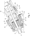
- Fig. 1 shows an exemplary structure of a tool holder 10 which can be used in the method according to the invention.
- a tool receiving section 11 for receiving a tool 90 (in Fig. 1 not shown, see Fig. 4 ).
- a tool 90 in Fig. 1 not shown, see Fig. 4 .
- several, for. B. six perforated disk-shaped first piezo elements 21 are arranged stacked, for example, which are connected to the tool receiving section 11 via a transmission section 12 and, for example, an ultrasonic transducer 20 (ultrasonic generator) for converting an electrical voltage into a mechanical vibration (e.g. with a frequency im Ultrasound area).
- the mechanical vibration of the first piezo elements 21 is transmitted to the tool 90 via the transmission section 12.
- the first piezo elements 21 can be designed, for example, as piezo ceramic disks with electrodes attached in between.
- the energy supply of the ultrasonic transducer 20 takes place, for example, via a transformer (first transformer), which, for example, on the machine side consists of a first pot core 31 and a primary winding 32 (in Fig. 1 not shown, see Fig. 4 ) and, for example, on the tool side consists of a second pot core 33 and a secondary coil 34, which are arranged, for example, as ring elements on the outside of the tool holder 10.
- first transformer which, for example, on the machine side consists of a first pot core 31 and a primary winding 32 (in Fig. 1 not shown, see Fig. 4 ) and, for example, on the tool side consists of a second pot core 33 and a secondary coil 34, which are arranged, for example, as ring elements on the outside of the tool holder 10.
- a perforated disk-shaped piezoelectric sensor element 40 is arranged, for example, which consists of a piezo element 41 and two contacts 42 and which is mechanically coupled to the first piezo elements 21, for example is electrically isolated from the first piezo elements 21 by an insulating element 43, which can consist of a ceramic perforated disk.
- the piezoelectric sensor element 40 is, for example, electrically isolated from a fastening element 13, for example a fastening nut, by a further insulation element 43.
- the fastening element 13 is used to fasten the piezoelectric sensor element 40 to the ultrasonic transducer 20 and to pretension the first piezo elements 21 because of the dynamic load.
- the first piezo elements 21 and the piezoelectric sensor element 40 are oriented in the same way, which on the one hand enables the generation and detection of the vibration in the same direction and on the other hand achieves a space-saving arrangement of the elements in the tool holder 10.
- the piezoelectric sensor element 40 converts the mechanical vibrations of the vibratory system, which consists of the tool 90, the transmission section 12, the ultrasonic transducer 20 and the piezoelectric Sensor element 40 is converted into a sensor signal, which is transmitted, for example, as an electrical voltage via a wire connection 50 from piezoelectric sensor element 40 through tool holder 10 to a transmitter element 61 and 62 on the outside of tool holder 10.
- the sensor signal is transmitted, for example, without contact to a machine-side receiver element 81 and 82 (in Fig. 1 not shown, see Fig. 4 ) transfer.
- the transmitter element 61 and 62 is part of a further transformer (second transformer) and consists, for example, of a first ferrite core 61 and a primary winding 62; the receiver element 81 and 82 is also part of the second transformer and consists of a second ferrite core 81 and a secondary winding 82.
- second transformer further transformer
- the sensor signal can be transmitted inductively from the tool holder 10 to a machine-side sensor signal evaluation device.
- the transmitter element 61 and 62 being designed as an LED and the receiver element 81 and 82 as a photodiode.
- the transmitter element 61 and 62 can be dimensioned and positioned in such a way that it fits into a bore 70 for a data chip for tool data according to the DIN 69893 standard.
- the tool holder 10 can be compared to a stationary part of the machine tool 1000 (in Fig. 1 not shown, see Fig. 4 ) be rotatable.
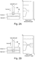
- Figure 2A shows schematically a machining process of a cutting tool 90 for ultrasonic machining on a workpiece WS, which consists of several layers of different materials (material A and material B).
- Figure 2B shows schematically the machining process after the cutting tool 90 has been dipped into the second material B for ultrasonic machining.
- the sensor signals of the piezo elements 21 change as shown in the diagram next to it.
- the change in material in the workpiece can be recognized and, preferably, the respective processing parameters such as rotational speed, cutting speed and / or feed of the tool, but also the vibration parameters such as parameters of the drive signals to the piezo elements 21 based on the recorded Sensor signals or adapted on the basis of the detection of the material change.
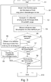
- Fig. 3 shows a flow chart of an embodiment of the method according to the invention.
- the tool 90 is operated on the basis of predetermined machining parameters.
- the ultrasonic vibration of the tool 90 is generated by the piezo elements 21, the signals from the piezoelectric sensor elements 40 such as amplitude, frequency and power being detected at the same time (step S4).
- step S5 a first evaluation of the detected sensor signals now takes place. It is z. B. checks whether the detected signals are essentially constant (in the range of a noise in the signal). If this is not the case, a temporal change t of the respective sensor signal is recorded in step S6, i.e. how quickly this signal changes, and at the same time the value change y of the respective sensor signal is recorded, i.e. how much or to what extent the corresponding signal changes changes.
- step S7 the change t over time is first compared with the previously established limit value t limit.
- the recorded change over time t is below the defined limit value tlimit, then in the next step S8 it is compared to what extent the value y has changed. For this purpose, the recorded change in value y is compared with the previously defined limit value y limit . If the detected change in value y is above the defined limit value y limit , the detected sensor signals speak for a change in material in the workpiece WS.
- the recorded values include a frequency of the vibration generated on the tool holder and / or a recorded power of the ultrasonic transducer 20.
- step S9 the specified machining parameters are adapted in step S9. This can include adapting or changing the feed rate of the tool and / or adapting or changing the cutting speed or rotation speed of the tool during the machining of the workpiece.
- the parameters can be adjusted as follows: After the sensor signals of the piezoelectric sensor elements 40 have been recorded, they are compared, for example, with data records which include sensor signals from correspondingly known materials that have already been recorded.
- These data sets can include resonance frequencies, for example of a tool-material combination or a damping capacity of a material, and are characteristic of every known material (like a kind of "fingerprint"). If a match is found, the present material is identified and the processing parameters can be adapted to the corresponding material on the basis of this.
- the type of material involved or the degree of hardness and damping capacity of this material can be estimated on the basis of the detected sensor signals and the processing parameters can be adapted on the basis of this. Material determinations are therefore also possible by way of example.
- processing parameters or processing parameter sets can already be specified for different materials or material layers of the workpiece, and when the change in the material of the workpiece is detected at the position of the tool tip of the tool, the processing parameters of the processing are set according to the various specified processing parameters or machining parameter sets adapted.
- step S8 Is however determined in step S8 that the change in value y of the corresponding sensor signal does not have a specified limit y cross exceeded, the process is continued with unchanged processing parameters.
- Fig. 4 shows schematically a device according to the invention with which the method according to the invention can be carried out.
- the device can be part of a machine tool 1000. Shown is a tool holder 10 with a piezoelectric sensor element 40, the structure of which is exemplified by that in FIG Fig. 1 tool holder 10 shown corresponds.
- the tool 90 for the ultrasonic machining of workpieces is received on the tool holder 10.
- a generator 120 outputs a work signal A1 as a drive signal for the piezo drive in the tool holder 10.
- the working signal A1 has the working frequency f1 and is transmitted without contact to the rotating tool holder 10 with the power P1 via the energy transfer device 30, which is designed as a transformer consisting of the primary winding 32 including the first pot core 31 and the secondary winding 34 including the second pot core 33.
- the generator also inputs 120 Test signal At a power Pt ⁇ P1, which is superimposed on the working signal A1 and whose frequency varies in a range around f1.
- the oscillatable system in the tool holder 10 is excited to oscillate, the frequency spectrum of which has essentially two frequencies.
- the piezoelectric sensor element 40 Due to the oscillation of the oscillatable system, the piezoelectric sensor element 40 also oscillates in the same way and thus generates an electrical sensor signal A2 which contains the information about the frequency spectrum of the oscillation.
- the sensor signal A2 is, for example, read out contactlessly by a reading device 130 from the rotating tool holder 10 and transmitted to an analysis device 140a via a further transformer, which consists of a primary winding 62 including a first ferrite core 61 and a secondary winding 82 including a second ferrite core 81.
- the analysis device 140a determines the frequencies contained in the frequency spectrum of A2, so that in a device for determining the resonance frequency 140b, which can be implemented as part of the analysis device 140a, the frequency of the largest peak in the spectrum (main frequency) can be assigned to the working frequency f1 and the frequency of the smaller peak in the spectrum (secondary frequency) can be assigned to the resonance frequency f2.
- the read-out device 130, the analysis device 140a and the device for determining the resonance frequency 140b can also be combined into two devices or implemented as a single device.
- the value of the determined resonance frequency f2 is transmitted to a first control device 150, which controls the generator 120 in such a way that the frequency f1 of the working signal A1 is adapted to the value of the resonance frequency f2.
- the value of the determined resonance frequency f2 can be transmitted to a second control device 160, which controls the generator 120 in such a way that the power P1, with which the work signal A1 is radiated into the tool holder 10, is increased to a power P1 ', so that even with an excitation with f1 ⁇ f2 the mechanical oscillation amplitude is reached that would be reached as the maximum amplitude with an excitation with the resonance frequency f2.
- the mechanical oscillation amplitude of the tool tip can be stabilized to a certain value, which has a positive effect on the precision during machining with the tool 90. If the oscillation amplitude is stabilized to the maximum possible value for a certain power, the efficiency of the workpiece machining also increases.
- a user of the device can control the first regulating device 150 and / or the second regulating device 160 via a user interface 170, so that the work signal A1 is only adapted on command of the user or when a specified condition occurs.
- the user can also specify that the working signal A1 is automatically adjusted at regular or irregular time intervals based on the last determined resonance frequency f2.
- the generator 120, the read-out device (or detection device) 130, the analysis device 140a and the first control device 150 can be combined to form a device 200 for outputting output signals and receiving input signals, a first output signal of this device 200 being the Working signal, a second output signal corresponds to the test signal At, and an input signal corresponds to the sensor signal A2.
- the vibration of the tool can be regulated at the respective resonance frequency of the vibration system. If the regulated resonance frequency or the associated power changes when the tool or its tool tip is at an interface between two materials, this can be used, according to exemplary embodiments of the invention, to detect a change in material.
- this can be the detection of an interface between two material layers in the workpiece, but this can also be an interface between the material of the workpiece, e.g. in the case of air pockets, cavities, bores, etc. in the workpiece or on the surface of the workpiece (air to workpiece surface) e.g. to detect the first contact with the workpiece.
Claims (10)
- Procédé pour l'usinage par enlèvement de copeaux d'une pièce (WS) sur une machine―outil (1000) à commande numérique au moyen d'un outil (90), comprenant :― la commande d'un mouvement relatif de l'outil (90) par rapport à la pièce (WS) pour l'usinage de la pièce (WS),― la génération d'une vibration ultrasonore de l'outil (90) au moyen d'un générateur d'ultrasons (20),― la détection d'au moins un signal de capteur (A2) émis à partir du générateur d'ultrasons (20), et― l'identification d'une modification de matériau sur la pièce (WS) pendant la commande du mouvement relatif de l'outil (90) par rapport à la pièce (WS) sur la base du au moins un signal de capteur (A2) émis à partir du générateur d'ultrasons (20),les paramètres d'usinage prédéfinis sont adaptés lorsque la modification temporelle et la modification de valeur du au moins un signal de capteur (A2) du générateur d'ultrasons (20) passe de manière correspondante au―dessous de la période de modification prédéfinie et simultanément dépasse la valeur de modification prédéfinie.dans lequel la commande du mouvement relatif de l'outil (90) par rapport à la pièce (WS) est mise en œuvre sur la base de paramètres d'usinage prédéfinis,dans lequel à l'étape d'identification d'une modification de matériau sur la pièce (WS), une modification temporelle et simultanément une modification de valeur d'un ou de plusieurs paramètres du signal de capteur (A2) du générateur d'ultrasons (20) est en outre détectée ;et dans lequel le procédé comprend en outre :― le fait d'établir si la modification temporelle et la modification de valeur du au moins un signal de capteur (A2) du générateur d'ultrasons (20) passe de manière correspondante au―dessous d'une période de modification prédéfinie et simultanément dépasse une valeur de modification prédéfinie, et
- Procédé selon la revendication 1, caractérisé en ce quela pièce (WS) comprend au moins deux zones de matériau différentes, etdans lequel à l'étape d'identification d'une modification de matériau sur la pièce (WS) une transition de l'outil (90) d'une zone de matériau dans l'autre zone de matériau de la pièce (WS) est identifiée.
- Procédé selon la revendication 2, caractérisé en ce que
la pièce (WS) comprend un matériau composite, en particulier un matériau composite renforcé par des fibres de carbone, et/ou un matériau en verre et/ou en céramique. - Procédé selon la revendication 2 ou 3, caractérisé en ce queles zones de matériau sont des couches de différents matériaux ou différentes natures de matériau ;les zones de matériau sont des inclusions de matériau dans la pièce (WS) ;et/oules zones de matériau sont des trous et/ou évidements dans la pièce (WS).
- Procédé selon l'une quelconque des revendications 1 à 4, caractérisé en ce que
à l'étape d'identification d'une modification de matériau sur la pièce (WS) un contact de l'outil (90) avec une surface de la pièce (WS) est identifié. - Procédé selon l'une quelconque des revendications 1 à 5, caractérisé en ce que
l'adaptation de paramètres d'usinage comprend au moins une adaptation d'une vitesse de rotation et/ou d'une avance du mouvement relatif de l'outil (90). - Procédé selon l'une quelconque des revendications 1 à 6, caractérisé en ce que
le générateur d'ultrasons (20) est un système d'actionneur piézoélectrique. - Dispositif pour une insertion sur une machine-outil (1000) pour l'usinage par enlèvement de copeaux d'une pièce (WS) au moyen d'un outil (90), en particulier selon l'une quelconque des revendications précédentes, dans lequel la machine―outil (1000) comprend une unité de commande pour la commande d'un mouvement relatif de l'outil (90) par rapport à la pièce (WS) pour l'usinage de la pièce (WS), un générateur d'ultrasons (20) pour la génération d'une vibration ultrasonore de l'outil (90), et une unité de détection pour la détection d'au moins un signal de capteur (A2) émis à partir du générateur d'ultrasons (20),dans lequel le dispositif comprend une unité d'évaluation qui est conçue pour identifier une modification de matériau sur la pièce (WS) pendant la commande du mouvement relatif de l'outil (90) par rapport à la pièce (WS) sur la base du au moins un signal de capteur (A2) émis à partir du générateur d'ultrasons (20), etdans lequel l'unité d'évaluation lors de l'identification de la modification de matériau sur la pièce (WS) détecte en outre une modification temporelle et simultanément une modification de valeur d'un ou plusieurs paramètres du signal de capteur (A2) du générateur d'ultrasons (20) ; etdans lequel le dispositif est configuré en outre pour :― établir si la modification temporelle et la modification de valeur du au moins un signal de capteur (A2) du générateur d'ultrasons (20) passe de manière correspondante au―dessous d'une période de modification prédéfinie et simultanément dépasse une valeur de modification prédéfinie, et― adapter les paramètres d'usinage prédéfinis lorsque la modification temporelle et la modification de valeur du au moins un signal de capteur (A2) du générateur d'ultrasons (20) passe de manière correspondante au― dessous de la période de modification prédéfinie et simultanément dépasse la valeur de modification prédéfinie.
- Machine―outil (1000) pour l'usinage d'une pièce (WS) au moyen d'un outil (90), comprenant :― une unité de commande pour la commande d'un mouvement relatif de l'outil (90) par rapport à la pièce (WS) pour l'usinage de la pièce (WS),― un générateur d'ultrasons (20) pour la génération d'une vibration ultrasonore de l'outil (90), et― une unité de détection pour la détection d'au moins un signal de capteur (A2) émis à partir du générateur d'ultrasons (20),caractérisée par
un dispositif selon la revendication 8. - Produit―programme informatique avec un programme informatique mis en mémoire sur un support de mémoire de données lisible par ordinateur, qui peut être exécuté sur une unité de commande numérique d'une machine―outil (1000) à commande numérique ou dans un ordinateur relié à une unité de commande d'une machine―outil (1000) à commande numérique, et qui est conçu pour exécuter sur la machine―outil (1000) le procédé selon l'une quelconque des revendications 1 à 7.
Priority Applications (1)
| Application Number | Priority Date | Filing Date | Title |
|---|---|---|---|
| PL17185214T PL3281741T3 (pl) | 2016-08-08 | 2017-08-08 | Sposób i urządzenie do obróbki przedmiotu obrabianego na obrabiarce sterowanej numerycznie |
Applications Claiming Priority (1)
| Application Number | Priority Date | Filing Date | Title |
|---|---|---|---|
| DE102016214699.8A DE102016214699A1 (de) | 2016-08-08 | 2016-08-08 | Verfahren und Vorrichtung zur Bearbeitung eines Werkstücks an einer numerisch gesteuerten Werkzeugmaschine |
Publications (2)
| Publication Number | Publication Date |
|---|---|
| EP3281741A1 EP3281741A1 (fr) | 2018-02-14 |
| EP3281741B1 true EP3281741B1 (fr) | 2021-12-15 |
Family
ID=59649494
Family Applications (1)
| Application Number | Title | Priority Date | Filing Date |
|---|---|---|---|
| EP17185214.8A Active EP3281741B1 (fr) | 2016-08-08 | 2017-08-08 | Procédé et dispositif de traitement d'une pièce d'usinage sur une machine-outil à commande numérique |
Country Status (10)
| Country | Link |
|---|---|
| US (1) | US10678219B2 (fr) |
| EP (1) | EP3281741B1 (fr) |
| JP (1) | JP6619399B2 (fr) |
| CN (1) | CN107695793B (fr) |
| CA (1) | CA2975574C (fr) |
| DE (1) | DE102016214699A1 (fr) |
| ES (1) | ES2904283T3 (fr) |
| PL (1) | PL3281741T3 (fr) |
| PT (1) | PT3281741T (fr) |
| RU (1) | RU2700628C2 (fr) |
Families Citing this family (8)
| Publication number | Priority date | Publication date | Assignee | Title |
|---|---|---|---|---|
| DE102017208909A1 (de) | 2017-05-26 | 2018-11-29 | Trumpf Werkzeugmaschinen Gmbh + Co. Kg | Verfahren zum Bestimmen von Materialeigenschaften eines Werkstücks durch Audioanalyse einer Werkstückbearbeitung sowie Stanzmaschine und Computerprogrammprodukt |
| CA3089042A1 (fr) | 2018-01-23 | 2019-08-01 | Quantum Impact, LLC | Procede et appareil d'usinage d'une piece |
| CN109894923B (zh) * | 2019-03-07 | 2020-11-27 | 中南大学 | 一种超声振动辅助加工中刀具稳定性控制方法 |
| DE102019003921B4 (de) * | 2019-06-05 | 2021-05-06 | Hufschmied Zerspanungssysteme Gmbh | Werkstückprüfverfahren und Werkstückprüfsystem |
| DE102019209191A1 (de) * | 2019-06-25 | 2020-12-31 | Sauer Gmbh | Verfahren und vorrichtung zum steuern einer ultraschall-werkzeugeinheit für die spanende bearbeitung an einer werkzeugmaschine |
| CN111843615B (zh) * | 2020-06-29 | 2021-07-20 | 中南大学 | 一种超声振动辅助加工中材料的断裂韧性的快速识别方法 |
| CN113714856B (zh) * | 2021-07-26 | 2023-06-27 | 豪丰茂五金制品(太仓)有限公司 | 一种数控机床的超声自动检测系统及其工作方法 |
| WO2023179844A1 (fr) | 2022-03-22 | 2023-09-28 | Schunk Sonosystems Gmbh | Procédé de commande d'un générateur d'ultrasons et générateur d'ultrasons |
Family Cites Families (28)
| Publication number | Priority date | Publication date | Assignee | Title |
|---|---|---|---|---|
| GB8810976D0 (en) * | 1988-05-10 | 1988-06-15 | Sra Dev Ltd | Cutting brittle materials |
| US5257531A (en) * | 1992-08-17 | 1993-11-02 | Masashi Motosugi | Apparatus for monitoring machining state of drill |
| US5940787A (en) * | 1993-12-10 | 1999-08-17 | U.S. Tech Corporation | Apparatuses and methods of monitoring the condition of tools and workpieces |
| TW320591B (fr) * | 1995-04-26 | 1997-11-21 | Fujitsu Ltd | |
| US5808396A (en) * | 1996-12-18 | 1998-09-15 | Alcon Laboratories, Inc. | System and method for tuning and controlling an ultrasonic handpiece |
| US6051500A (en) * | 1998-05-19 | 2000-04-18 | Lucent Technologies Inc. | Device and method for polishing a semiconductor substrate |
| DE19960824C2 (de) * | 1999-12-16 | 2003-08-21 | Hilti Ag | Verfahren und Einrichtung zur Untersuchung und Identifizierung der Art eines Untergrunds |
| US6637986B2 (en) * | 2001-11-26 | 2003-10-28 | Delphi Technologies, Inc. | Drilling apparatus and method |
| JP2005224891A (ja) * | 2004-02-12 | 2005-08-25 | Kyoritsu Seiki Kk | ドリルホルダー |
| JP4842936B2 (ja) | 2004-07-02 | 2011-12-21 | ザウアー ゲーエムベーハー | 振動ヘッドを有するツール |
| EP1669148B1 (fr) * | 2004-12-13 | 2018-01-17 | Fritz Studer AG | Ensemble porte-outils d'usinage rotatif assisté par ultra-sons |
| JP2008140037A (ja) * | 2006-11-30 | 2008-06-19 | Matsushita Electric Works Ltd | 加工監視装置 |
| DE102007013055B4 (de) * | 2007-03-19 | 2015-11-26 | Sauer Ultrasonic Gmbh | Verfahren und Vorrichtung zum Bestimmen der Frequenzkennlinie und zum Betreiben eines Ultraschallwerkzeugs |
| DE102007042280A1 (de) * | 2007-09-06 | 2009-03-12 | Komet Group Holding Gmbh | Bohrwerkzeug für Werkzeugmaschinen sowie Verfahren zu dessen Herstellung |
| US8180479B2 (en) * | 2008-02-05 | 2012-05-15 | The Boeing Company | Adaptive control of composite plycutting |
| US8317437B2 (en) * | 2008-08-01 | 2012-11-27 | The Boeing Company | Adaptive positive feed drilling system |
| FR2944722B1 (fr) * | 2009-04-28 | 2014-10-10 | Arts | Tete de percage a vibrations axiales |
| JP5622463B2 (ja) * | 2010-07-09 | 2014-11-12 | 株式会社スギノマシン | 穴あけ加工制御方法および穴あけ加工装置 |
| JP5573459B2 (ja) * | 2010-07-27 | 2014-08-20 | 株式会社ジェイテクト | 研削方法および研削盤 |
| DE102010048636B4 (de) * | 2010-10-15 | 2017-11-16 | Sauer Ultrasonic Gmbh | Werkzeugmaschine und Verfahren zur Bearbeitung eines Werkstücks mit einem Werkzeug |
| JP5747576B2 (ja) * | 2011-03-11 | 2015-07-15 | トヨタ紡織株式会社 | 超音波切断装置及びこれを用いる車両用内装材の製造方法 |
| EP2803455A1 (fr) | 2013-05-13 | 2014-11-19 | A O Schallinox GmbH | Dispositif de coupe d'un produit de processus |
| CN104552422A (zh) * | 2013-10-29 | 2015-04-29 | 青岛天恒机械有限公司 | 复合材料的超声辅助切削加工技术 |
| CN104647147A (zh) * | 2013-11-25 | 2015-05-27 | 大连康赛谱科技发展有限公司 | 一种碳纤维复合材料旋转超声铣磨加工装置及方法 |
| KR101561531B1 (ko) * | 2014-04-25 | 2015-11-02 | 한국기계연구원 | 초음파 밀링 가공 장치 |
| DE102015105338A1 (de) * | 2015-04-08 | 2016-10-27 | Lti Motion Gmbh | Werkzeugantrieb mit Spindelwelle und Betriebsverfahren |
| JP6695102B2 (ja) * | 2015-05-26 | 2020-05-20 | 株式会社ディスコ | 加工システム |
| US10232446B2 (en) * | 2015-11-16 | 2019-03-19 | Apex Brands, Inc. | Adaptive drilling with piezo-electric feed oscillator |
-
2016
- 2016-08-08 DE DE102016214699.8A patent/DE102016214699A1/de not_active Ceased
-
2017
- 2017-08-02 JP JP2017149869A patent/JP6619399B2/ja active Active
- 2017-08-04 CA CA2975574A patent/CA2975574C/fr not_active Expired - Fee Related
- 2017-08-04 RU RU2017127899A patent/RU2700628C2/ru active
- 2017-08-08 ES ES17185214T patent/ES2904283T3/es active Active
- 2017-08-08 PT PT171852148T patent/PT3281741T/pt unknown
- 2017-08-08 PL PL17185214T patent/PL3281741T3/pl unknown
- 2017-08-08 CN CN201710672201.XA patent/CN107695793B/zh active Active
- 2017-08-08 EP EP17185214.8A patent/EP3281741B1/fr active Active
- 2017-08-08 US US15/671,517 patent/US10678219B2/en active Active
Non-Patent Citations (1)
| Title |
|---|
| None * |
Also Published As
| Publication number | Publication date |
|---|---|
| DE102016214699A1 (de) | 2018-02-08 |
| JP2018039107A (ja) | 2018-03-15 |
| ES2904283T3 (es) | 2022-04-04 |
| EP3281741A1 (fr) | 2018-02-14 |
| CA2975574C (fr) | 2019-06-18 |
| CN107695793A (zh) | 2018-02-16 |
| US10678219B2 (en) | 2020-06-09 |
| RU2017127899A (ru) | 2019-02-04 |
| PL3281741T3 (pl) | 2022-03-07 |
| RU2017127899A3 (fr) | 2019-02-04 |
| CA2975574A1 (fr) | 2018-02-08 |
| US20180039255A1 (en) | 2018-02-08 |
| RU2700628C2 (ru) | 2019-09-19 |
| JP6619399B2 (ja) | 2019-12-11 |
| PT3281741T (pt) | 2022-02-14 |
| CN107695793B (zh) | 2021-11-23 |
Similar Documents
| Publication | Publication Date | Title |
|---|---|---|
| EP3281741B1 (fr) | Procédé et dispositif de traitement d'une pièce d'usinage sur une machine-outil à commande numérique | |
| EP3320312B1 (fr) | Procédé et dispositif pour mesurer la fréquence de résonance d'un outil mis en vibrations par ultrasons pour un usinage par enlèvement de copeaux | |
| DE102010048638B4 (de) | Werkzeugmaschine, Werkstückbearbeitungsverfahren | |
| DE102012219254B4 (de) | Versorgungsschaltung, Versorgungssystem, Werkzeugaktor, Werkzeug | |
| WO2017005917A1 (fr) | Dispositif pour générer la vibration ultrasonore d'un outil et pour mesurer des paramètres de vibrations | |
| DE3530560A1 (de) | Akustische abtastung einer beruehrung zwischen einem schneidwerkzeug und einem werkstueck | |
| DE102016114378A1 (de) | Handhabungsvorrichtung und Verfahren zur Überwachung einer Handhabungsvorrichtung | |
| EP3347685A1 (fr) | Procédé et dispositif pour déterminer une amplitude de vibration d'un outil | |
| DE102016125803A1 (de) | Werkzeugmaschine, insbesondere Schleifmaschine, sowie Verfahren zur Ermittlung eines Ist-Zustandes einer Werkzeugmaschine | |
| DE102016108498A1 (de) | Bearbeitungssystem zum anpassen der drehzahl eines bearbeitungswerkzeugs und der vorschubgeschwindigkeit eines werkstücks | |
| DE102007048961A1 (de) | Verfahren zur Bearbeitung eines Werkstücks mit einer Werkzeugmaschine | |
| DE102019207746A1 (de) | Verfahren zum Ermitteln einer Zustandsinformation betreffend eine Bandschleifmaschine mittels eines maschinellen Lernsystems | |
| DE3608572C2 (fr) | ||
| DE3618080A1 (de) | Hochgeschwindigkeitsbearbeitung-steuereinheit | |
| DE4228333A1 (de) | Zerspanungsvorrichtung | |
| WO2007025404A1 (fr) | Systeme de controle de l'etat d'un outil | |
| DE19643383A1 (de) | Materialbearbeitungsvorrichtung und Verfahren zur Überwachung und Steuerung eines Materialbearbeitungsvorgangs | |
| WO2020260189A1 (fr) | Procédé et dispositif de commande d'une unité d'outil ultrasonique pour l'usinage par enlèvement de copeaux sur une machine-outil | |
| DE102006062126A1 (de) | Rotationswerkzeug, Verfahren zur Schwingungsdämpfung und Vorrichtung zur Durchführung des Verfahrens | |
| DE3828101C2 (fr) | ||
| DE4432608B4 (de) | Vorrichtung und Verfahren zur Werkzeugbrucherkennung in Werkzeugmaschinen | |
| WO2019072574A1 (fr) | Procédé de détermination d'erreurs de position de perçages et sécurité du processus de perçage | |
| DE10340697A1 (de) | Einrichtung zum Erfassen, Bewerten und Verändern des dynamischen Verhaltens von Rotierenden Zerspanungswerkzeugen | |
| DE102017105257A1 (de) | Spannmittelanordnung für eine Werkzeugmaschine sowie Werkzeugmaschine mit der Spannmittelanordnung | |
| DD146501A1 (de) | Verfahren und anordnung zur charakterisierung des spanungsprozesses |
Legal Events
| Date | Code | Title | Description |
|---|---|---|---|
| PUAI | Public reference made under article 153(3) epc to a published international application that has entered the european phase |
Free format text: ORIGINAL CODE: 0009012 |
|
| STAA | Information on the status of an ep patent application or granted ep patent |
Free format text: STATUS: THE APPLICATION HAS BEEN PUBLISHED |
|
| AK | Designated contracting states |
Kind code of ref document: A1 Designated state(s): AL AT BE BG CH CY CZ DE DK EE ES FI FR GB GR HR HU IE IS IT LI LT LU LV MC MK MT NL NO PL PT RO RS SE SI SK SM TR |
|
| AX | Request for extension of the european patent |
Extension state: BA ME |
|
| STAA | Information on the status of an ep patent application or granted ep patent |
Free format text: STATUS: REQUEST FOR EXAMINATION WAS MADE |
|
| 17P | Request for examination filed |
Effective date: 20180814 |
|
| RBV | Designated contracting states (corrected) |
Designated state(s): AL AT BE BG CH CY CZ DE DK EE ES FI FR GB GR HR HU IE IS IT LI LT LU LV MC MK MT NL NO PL PT RO RS SE SI SK SM TR |
|
| STAA | Information on the status of an ep patent application or granted ep patent |
Free format text: STATUS: EXAMINATION IS IN PROGRESS |
|
| STAA | Information on the status of an ep patent application or granted ep patent |
Free format text: STATUS: EXAMINATION IS IN PROGRESS |
|
| 17Q | First examination report despatched |
Effective date: 20201202 |
|
| REG | Reference to a national code |
Ref country code: DE Ref legal event code: R079 Ref document number: 502017012234 Country of ref document: DE Free format text: PREVIOUS MAIN CLASS: B23Q0017090000 Ipc: B23B0049000000 |
|
| GRAP | Despatch of communication of intention to grant a patent |
Free format text: ORIGINAL CODE: EPIDOSNIGR1 |
|
| STAA | Information on the status of an ep patent application or granted ep patent |
Free format text: STATUS: GRANT OF PATENT IS INTENDED |
|
| RIC1 | Information provided on ipc code assigned before grant |
Ipc: B23B 49/00 20060101AFI20210628BHEP |
|
| INTG | Intention to grant announced |
Effective date: 20210721 |
|
| RAP3 | Party data changed (applicant data changed or rights of an application transferred) |
Owner name: DMG MORI ULTRASONIC LASERTEC GMBH |
|
| GRAS | Grant fee paid |
Free format text: ORIGINAL CODE: EPIDOSNIGR3 |
|
| GRAA | (expected) grant |
Free format text: ORIGINAL CODE: 0009210 |
|
| STAA | Information on the status of an ep patent application or granted ep patent |
Free format text: STATUS: THE PATENT HAS BEEN GRANTED |
|
| AK | Designated contracting states |
Kind code of ref document: B1 Designated state(s): AL AT BE BG CH CY CZ DE DK EE ES FI FR GB GR HR HU IE IS IT LI LT LU LV MC MK MT NL NO PL PT RO RS SE SI SK SM TR |
|
| REG | Reference to a national code |
Ref country code: GB Ref legal event code: FG4D Free format text: NOT ENGLISH Ref country code: CH Ref legal event code: EP |
|
| REG | Reference to a national code |
Ref country code: DE Ref legal event code: R096 Ref document number: 502017012234 Country of ref document: DE |
|
| REG | Reference to a national code |
Ref country code: IE Ref legal event code: FG4D Free format text: LANGUAGE OF EP DOCUMENT: GERMAN |
|
| REG | Reference to a national code |
Ref country code: AT Ref legal event code: REF Ref document number: 1455108 Country of ref document: AT Kind code of ref document: T Effective date: 20220115 |
|
| REG | Reference to a national code |
Ref country code: NL Ref legal event code: FP |
|
| REG | Reference to a national code |
Ref country code: PT Ref legal event code: SC4A Ref document number: 3281741 Country of ref document: PT Date of ref document: 20220214 Kind code of ref document: T Free format text: AVAILABILITY OF NATIONAL TRANSLATION Effective date: 20220208 |
|
| REG | Reference to a national code |
Ref country code: SE Ref legal event code: TRGR |
|
| REG | Reference to a national code |
Ref country code: RO Ref legal event code: EPE |
|
| REG | Reference to a national code |
Ref country code: ES Ref legal event code: FG2A Ref document number: 2904283 Country of ref document: ES Kind code of ref document: T3 Effective date: 20220404 |
|
| REG | Reference to a national code |
Ref country code: LT Ref legal event code: MG9D |
|
| PG25 | Lapsed in a contracting state [announced via postgrant information from national office to epo] |
Ref country code: RS Free format text: LAPSE BECAUSE OF FAILURE TO SUBMIT A TRANSLATION OF THE DESCRIPTION OR TO PAY THE FEE WITHIN THE PRESCRIBED TIME-LIMIT Effective date: 20211215 Ref country code: LT Free format text: LAPSE BECAUSE OF FAILURE TO SUBMIT A TRANSLATION OF THE DESCRIPTION OR TO PAY THE FEE WITHIN THE PRESCRIBED TIME-LIMIT Effective date: 20211215 Ref country code: FI Free format text: LAPSE BECAUSE OF FAILURE TO SUBMIT A TRANSLATION OF THE DESCRIPTION OR TO PAY THE FEE WITHIN THE PRESCRIBED TIME-LIMIT Effective date: 20211215 Ref country code: BG Free format text: LAPSE BECAUSE OF FAILURE TO SUBMIT A TRANSLATION OF THE DESCRIPTION OR TO PAY THE FEE WITHIN THE PRESCRIBED TIME-LIMIT Effective date: 20220315 |
|
| PG25 | Lapsed in a contracting state [announced via postgrant information from national office to epo] |
Ref country code: NO Free format text: LAPSE BECAUSE OF FAILURE TO SUBMIT A TRANSLATION OF THE DESCRIPTION OR TO PAY THE FEE WITHIN THE PRESCRIBED TIME-LIMIT Effective date: 20220315 Ref country code: LV Free format text: LAPSE BECAUSE OF FAILURE TO SUBMIT A TRANSLATION OF THE DESCRIPTION OR TO PAY THE FEE WITHIN THE PRESCRIBED TIME-LIMIT Effective date: 20211215 Ref country code: HR Free format text: LAPSE BECAUSE OF FAILURE TO SUBMIT A TRANSLATION OF THE DESCRIPTION OR TO PAY THE FEE WITHIN THE PRESCRIBED TIME-LIMIT Effective date: 20211215 Ref country code: GR Free format text: LAPSE BECAUSE OF FAILURE TO SUBMIT A TRANSLATION OF THE DESCRIPTION OR TO PAY THE FEE WITHIN THE PRESCRIBED TIME-LIMIT Effective date: 20220316 |
|
| PG25 | Lapsed in a contracting state [announced via postgrant information from national office to epo] |
Ref country code: SM Free format text: LAPSE BECAUSE OF FAILURE TO SUBMIT A TRANSLATION OF THE DESCRIPTION OR TO PAY THE FEE WITHIN THE PRESCRIBED TIME-LIMIT Effective date: 20211215 Ref country code: SK Free format text: LAPSE BECAUSE OF FAILURE TO SUBMIT A TRANSLATION OF THE DESCRIPTION OR TO PAY THE FEE WITHIN THE PRESCRIBED TIME-LIMIT Effective date: 20211215 Ref country code: EE Free format text: LAPSE BECAUSE OF FAILURE TO SUBMIT A TRANSLATION OF THE DESCRIPTION OR TO PAY THE FEE WITHIN THE PRESCRIBED TIME-LIMIT Effective date: 20211215 |
|
| REG | Reference to a national code |
Ref country code: DE Ref legal event code: R097 Ref document number: 502017012234 Country of ref document: DE |
|
| PG25 | Lapsed in a contracting state [announced via postgrant information from national office to epo] |
Ref country code: IS Free format text: LAPSE BECAUSE OF FAILURE TO SUBMIT A TRANSLATION OF THE DESCRIPTION OR TO PAY THE FEE WITHIN THE PRESCRIBED TIME-LIMIT Effective date: 20220415 |
|
| PLBE | No opposition filed within time limit |
Free format text: ORIGINAL CODE: 0009261 |
|
| STAA | Information on the status of an ep patent application or granted ep patent |
Free format text: STATUS: NO OPPOSITION FILED WITHIN TIME LIMIT |
|
| PG25 | Lapsed in a contracting state [announced via postgrant information from national office to epo] |
Ref country code: DK Free format text: LAPSE BECAUSE OF FAILURE TO SUBMIT A TRANSLATION OF THE DESCRIPTION OR TO PAY THE FEE WITHIN THE PRESCRIBED TIME-LIMIT Effective date: 20211215 Ref country code: AL Free format text: LAPSE BECAUSE OF FAILURE TO SUBMIT A TRANSLATION OF THE DESCRIPTION OR TO PAY THE FEE WITHIN THE PRESCRIBED TIME-LIMIT Effective date: 20211215 |
|
| 26N | No opposition filed |
Effective date: 20220916 |
|
| PG25 | Lapsed in a contracting state [announced via postgrant information from national office to epo] |
Ref country code: SI Free format text: LAPSE BECAUSE OF FAILURE TO SUBMIT A TRANSLATION OF THE DESCRIPTION OR TO PAY THE FEE WITHIN THE PRESCRIBED TIME-LIMIT Effective date: 20211215 |
|
| PG25 | Lapsed in a contracting state [announced via postgrant information from national office to epo] |
Ref country code: MC Free format text: LAPSE BECAUSE OF FAILURE TO SUBMIT A TRANSLATION OF THE DESCRIPTION OR TO PAY THE FEE WITHIN THE PRESCRIBED TIME-LIMIT Effective date: 20211215 |
|
| PG25 | Lapsed in a contracting state [announced via postgrant information from national office to epo] |
Ref country code: LU Free format text: LAPSE BECAUSE OF NON-PAYMENT OF DUE FEES Effective date: 20220808 |
|
| PG25 | Lapsed in a contracting state [announced via postgrant information from national office to epo] |
Ref country code: IE Free format text: LAPSE BECAUSE OF NON-PAYMENT OF DUE FEES Effective date: 20220808 |
|
| PGFP | Annual fee paid to national office [announced via postgrant information from national office to epo] |
Ref country code: NL Payment date: 20230823 Year of fee payment: 7 |
|
| PGFP | Annual fee paid to national office [announced via postgrant information from national office to epo] |
Ref country code: TR Payment date: 20230801 Year of fee payment: 7 Ref country code: RO Payment date: 20230802 Year of fee payment: 7 Ref country code: IT Payment date: 20230831 Year of fee payment: 7 Ref country code: GB Payment date: 20230824 Year of fee payment: 7 Ref country code: ES Payment date: 20230918 Year of fee payment: 7 Ref country code: CZ Payment date: 20230726 Year of fee payment: 7 Ref country code: CH Payment date: 20230902 Year of fee payment: 7 Ref country code: AT Payment date: 20230818 Year of fee payment: 7 |
|
| PGFP | Annual fee paid to national office [announced via postgrant information from national office to epo] |
Ref country code: SE Payment date: 20230823 Year of fee payment: 7 Ref country code: PT Payment date: 20230726 Year of fee payment: 7 Ref country code: PL Payment date: 20230726 Year of fee payment: 7 Ref country code: FR Payment date: 20230821 Year of fee payment: 7 Ref country code: DE Payment date: 20230831 Year of fee payment: 7 Ref country code: BE Payment date: 20230822 Year of fee payment: 7 |
|
| PG25 | Lapsed in a contracting state [announced via postgrant information from national office to epo] |
Ref country code: HU Free format text: LAPSE BECAUSE OF FAILURE TO SUBMIT A TRANSLATION OF THE DESCRIPTION OR TO PAY THE FEE WITHIN THE PRESCRIBED TIME-LIMIT; INVALID AB INITIO Effective date: 20170808 |