EP3281741B1 - Method and device for machining a workpiece on a numerically controlled machine tool - Google Patents
Method and device for machining a workpiece on a numerically controlled machine tool Download PDFInfo
- Publication number
- EP3281741B1 EP3281741B1 EP17185214.8A EP17185214A EP3281741B1 EP 3281741 B1 EP3281741 B1 EP 3281741B1 EP 17185214 A EP17185214 A EP 17185214A EP 3281741 B1 EP3281741 B1 EP 3281741B1
- Authority
- EP
- European Patent Office
- Prior art keywords
- workpiece
- tool
- change
- sensor signal
- machining
- Prior art date
- Legal status (The legal status is an assumption and is not a legal conclusion. Google has not performed a legal analysis and makes no representation as to the accuracy of the status listed.)
- Active
Links
- 238000003754 machining Methods 0.000 title claims description 61
- 238000000034 method Methods 0.000 title claims description 51
- 239000000463 material Substances 0.000 claims description 118
- 230000008859 change Effects 0.000 claims description 98
- 238000011156 evaluation Methods 0.000 claims description 13
- 238000004590 computer program Methods 0.000 claims description 8
- 238000002604 ultrasonography Methods 0.000 claims description 8
- 230000002123 temporal effect Effects 0.000 claims description 7
- 239000002131 composite material Substances 0.000 claims description 4
- 239000011521 glass Substances 0.000 claims description 4
- 230000007704 transition Effects 0.000 claims description 3
- 229920000049 Carbon (fiber) Polymers 0.000 claims description 2
- 239000004917 carbon fiber Substances 0.000 claims description 2
- 229910010293 ceramic material Inorganic materials 0.000 claims description 2
- 238000013500 data storage Methods 0.000 claims description 2
- VNWKTOKETHGBQD-UHFFFAOYSA-N methane Chemical compound C VNWKTOKETHGBQD-UHFFFAOYSA-N 0.000 claims description 2
- 239000011208 reinforced composite material Substances 0.000 claims description 2
- 238000012545 processing Methods 0.000 description 30
- 238000004804 winding Methods 0.000 description 16
- 230000008901 benefit Effects 0.000 description 11
- 230000005540 biological transmission Effects 0.000 description 11
- 238000013016 damping Methods 0.000 description 9
- 238000001514 detection method Methods 0.000 description 8
- 230000006978 adaptation Effects 0.000 description 6
- 230000001276 controlling effect Effects 0.000 description 6
- 229910000859 α-Fe Inorganic materials 0.000 description 6
- 238000005259 measurement Methods 0.000 description 5
- 230000008569 process Effects 0.000 description 5
- 230000001105 regulatory effect Effects 0.000 description 5
- 238000001228 spectrum Methods 0.000 description 5
- 239000000919 ceramic Substances 0.000 description 4
- 230000010355 oscillation Effects 0.000 description 4
- 238000012546 transfer Methods 0.000 description 4
- 238000011161 development Methods 0.000 description 3
- 238000010586 diagram Methods 0.000 description 3
- 230000009467 reduction Effects 0.000 description 3
- 230000005284 excitation Effects 0.000 description 2
- 230000001965 increasing effect Effects 0.000 description 2
- 238000009413 insulation Methods 0.000 description 2
- 230000010358 mechanical oscillation Effects 0.000 description 2
- 238000012360 testing method Methods 0.000 description 2
- RTAQQCXQSZGOHL-UHFFFAOYSA-N Titanium Chemical compound [Ti] RTAQQCXQSZGOHL-UHFFFAOYSA-N 0.000 description 1
- XAGFODPZIPBFFR-UHFFFAOYSA-N aluminium Chemical compound [Al] XAGFODPZIPBFFR-UHFFFAOYSA-N 0.000 description 1
- 229910052782 aluminium Inorganic materials 0.000 description 1
- 238000013459 approach Methods 0.000 description 1
- 239000004918 carbon fiber reinforced polymer Substances 0.000 description 1
- 239000013078 crystal Substances 0.000 description 1
- 230000001419 dependent effect Effects 0.000 description 1
- 238000005553 drilling Methods 0.000 description 1
- 230000000694 effects Effects 0.000 description 1
- 238000010292 electrical insulation Methods 0.000 description 1
- 238000010438 heat treatment Methods 0.000 description 1
- 238000007654 immersion Methods 0.000 description 1
- 230000001939 inductive effect Effects 0.000 description 1
- 230000001788 irregular Effects 0.000 description 1
- 239000000203 mixture Substances 0.000 description 1
- 230000003287 optical effect Effects 0.000 description 1
- 230000008092 positive effect Effects 0.000 description 1
- 230000008054 signal transmission Effects 0.000 description 1
- 230000004936 stimulating effect Effects 0.000 description 1
- 229910052719 titanium Inorganic materials 0.000 description 1
- 239000010936 titanium Substances 0.000 description 1
Images

Classifications
-
- G—PHYSICS
- G05—CONTROLLING; REGULATING
- G05B—CONTROL OR REGULATING SYSTEMS IN GENERAL; FUNCTIONAL ELEMENTS OF SUCH SYSTEMS; MONITORING OR TESTING ARRANGEMENTS FOR SUCH SYSTEMS OR ELEMENTS
- G05B19/00—Programme-control systems
- G05B19/02—Programme-control systems electric
- G05B19/18—Numerical control [NC], i.e. automatically operating machines, in particular machine tools, e.g. in a manufacturing environment, so as to execute positioning, movement or co-ordinated operations by means of programme data in numerical form
- G05B19/416—Numerical control [NC], i.e. automatically operating machines, in particular machine tools, e.g. in a manufacturing environment, so as to execute positioning, movement or co-ordinated operations by means of programme data in numerical form characterised by control of velocity, acceleration or deceleration
-
- B—PERFORMING OPERATIONS; TRANSPORTING
- B23—MACHINE TOOLS; METAL-WORKING NOT OTHERWISE PROVIDED FOR
- B23B—TURNING; BORING
- B23B37/00—Boring by making use of ultrasonic energy
-
- B—PERFORMING OPERATIONS; TRANSPORTING
- B23—MACHINE TOOLS; METAL-WORKING NOT OTHERWISE PROVIDED FOR
- B23B—TURNING; BORING
- B23B49/00—Measuring or gauging equipment on boring machines for positioning or guiding the drill; Devices for indicating failure of drills during boring; Centering devices for holes to be bored
-
- B—PERFORMING OPERATIONS; TRANSPORTING
- B23—MACHINE TOOLS; METAL-WORKING NOT OTHERWISE PROVIDED FOR
- B23Q—DETAILS, COMPONENTS, OR ACCESSORIES FOR MACHINE TOOLS, e.g. ARRANGEMENTS FOR COPYING OR CONTROLLING; MACHINE TOOLS IN GENERAL CHARACTERISED BY THE CONSTRUCTION OF PARTICULAR DETAILS OR COMPONENTS; COMBINATIONS OR ASSOCIATIONS OF METAL-WORKING MACHINES, NOT DIRECTED TO A PARTICULAR RESULT
- B23Q15/00—Automatic control or regulation of feed movement, cutting velocity or position of tool or work
- B23Q15/007—Automatic control or regulation of feed movement, cutting velocity or position of tool or work while the tool acts upon the workpiece
- B23Q15/013—Control or regulation of feed movement
-
- B—PERFORMING OPERATIONS; TRANSPORTING
- B23—MACHINE TOOLS; METAL-WORKING NOT OTHERWISE PROVIDED FOR
- B23Q—DETAILS, COMPONENTS, OR ACCESSORIES FOR MACHINE TOOLS, e.g. ARRANGEMENTS FOR COPYING OR CONTROLLING; MACHINE TOOLS IN GENERAL CHARACTERISED BY THE CONSTRUCTION OF PARTICULAR DETAILS OR COMPONENTS; COMBINATIONS OR ASSOCIATIONS OF METAL-WORKING MACHINES, NOT DIRECTED TO A PARTICULAR RESULT
- B23Q15/00—Automatic control or regulation of feed movement, cutting velocity or position of tool or work
- B23Q15/007—Automatic control or regulation of feed movement, cutting velocity or position of tool or work while the tool acts upon the workpiece
- B23Q15/12—Adaptive control, i.e. adjusting itself to have a performance which is optimum according to a preassigned criterion
-
- B—PERFORMING OPERATIONS; TRANSPORTING
- B23—MACHINE TOOLS; METAL-WORKING NOT OTHERWISE PROVIDED FOR
- B23Q—DETAILS, COMPONENTS, OR ACCESSORIES FOR MACHINE TOOLS, e.g. ARRANGEMENTS FOR COPYING OR CONTROLLING; MACHINE TOOLS IN GENERAL CHARACTERISED BY THE CONSTRUCTION OF PARTICULAR DETAILS OR COMPONENTS; COMBINATIONS OR ASSOCIATIONS OF METAL-WORKING MACHINES, NOT DIRECTED TO A PARTICULAR RESULT
- B23Q15/00—Automatic control or regulation of feed movement, cutting velocity or position of tool or work
- B23Q15/007—Automatic control or regulation of feed movement, cutting velocity or position of tool or work while the tool acts upon the workpiece
- B23Q15/18—Compensation of tool-deflection due to temperature or force
-
- B—PERFORMING OPERATIONS; TRANSPORTING
- B23—MACHINE TOOLS; METAL-WORKING NOT OTHERWISE PROVIDED FOR
- B23Q—DETAILS, COMPONENTS, OR ACCESSORIES FOR MACHINE TOOLS, e.g. ARRANGEMENTS FOR COPYING OR CONTROLLING; MACHINE TOOLS IN GENERAL CHARACTERISED BY THE CONSTRUCTION OF PARTICULAR DETAILS OR COMPONENTS; COMBINATIONS OR ASSOCIATIONS OF METAL-WORKING MACHINES, NOT DIRECTED TO A PARTICULAR RESULT
- B23Q17/00—Arrangements for observing, indicating or measuring on machine tools
- B23Q17/09—Arrangements for observing, indicating or measuring on machine tools for indicating or measuring cutting pressure or for determining cutting-tool condition, e.g. cutting ability, load on tool
- B23Q17/0952—Arrangements for observing, indicating or measuring on machine tools for indicating or measuring cutting pressure or for determining cutting-tool condition, e.g. cutting ability, load on tool during machining
-
- B—PERFORMING OPERATIONS; TRANSPORTING
- B23—MACHINE TOOLS; METAL-WORKING NOT OTHERWISE PROVIDED FOR
- B23Q—DETAILS, COMPONENTS, OR ACCESSORIES FOR MACHINE TOOLS, e.g. ARRANGEMENTS FOR COPYING OR CONTROLLING; MACHINE TOOLS IN GENERAL CHARACTERISED BY THE CONSTRUCTION OF PARTICULAR DETAILS OR COMPONENTS; COMBINATIONS OR ASSOCIATIONS OF METAL-WORKING MACHINES, NOT DIRECTED TO A PARTICULAR RESULT
- B23Q17/00—Arrangements for observing, indicating or measuring on machine tools
- B23Q17/20—Arrangements for observing, indicating or measuring on machine tools for indicating or measuring workpiece characteristics, e.g. contour, dimension, hardness
-
- G—PHYSICS
- G01—MEASURING; TESTING
- G01B—MEASURING LENGTH, THICKNESS OR SIMILAR LINEAR DIMENSIONS; MEASURING ANGLES; MEASURING AREAS; MEASURING IRREGULARITIES OF SURFACES OR CONTOURS
- G01B17/00—Measuring arrangements characterised by the use of infrasonic, sonic or ultrasonic vibrations
-
- B—PERFORMING OPERATIONS; TRANSPORTING
- B23—MACHINE TOOLS; METAL-WORKING NOT OTHERWISE PROVIDED FOR
- B23B—TURNING; BORING
- B23B2260/00—Details of constructional elements
- B23B2260/128—Sensors
-
- B—PERFORMING OPERATIONS; TRANSPORTING
- B23—MACHINE TOOLS; METAL-WORKING NOT OTHERWISE PROVIDED FOR
- B23B—TURNING; BORING
- B23B2270/00—Details of turning, boring or drilling machines, processes or tools not otherwise provided for
- B23B2270/10—Use of ultrasound
-
- B—PERFORMING OPERATIONS; TRANSPORTING
- B23—MACHINE TOOLS; METAL-WORKING NOT OTHERWISE PROVIDED FOR
- B23B—TURNING; BORING
- B23B2270/00—Details of turning, boring or drilling machines, processes or tools not otherwise provided for
- B23B2270/48—Measuring or detecting
-
- G—PHYSICS
- G05—CONTROLLING; REGULATING
- G05B—CONTROL OR REGULATING SYSTEMS IN GENERAL; FUNCTIONAL ELEMENTS OF SUCH SYSTEMS; MONITORING OR TESTING ARRANGEMENTS FOR SUCH SYSTEMS OR ELEMENTS
- G05B2219/00—Program-control systems
- G05B2219/30—Nc systems
- G05B2219/45—Nc applications
- G05B2219/45206—Ultrasonic drill, mill, machining
Definitions
- the present invention relates to a method for machining a workpiece by means of a tool on a numerically controlled machine tool.
- the present invention also relates to a device and a machine tool on which the aforementioned method can be carried out.
- the present invention also relates to a computer program product with which the aforementioned method can be carried out.
- Machine tools are known in the prior art in which, for example, when a workpiece is machined by a tool, the rotational movement of the tool can be superimposed by an ultrasonic vibration of the tool.
- EP 1 763 416 B1 describes in this context a tool with a tool holder which has a tool holder receptacle at a first end for adapting to a rotatable spindle nose, and a tool receptacle at a second end opposite the first end, and with a tool head that can be inserted into the tool receptacle, the tool holder having a Includes vibration motor.
- an ultrasonic generator in the tool holder that generates the ultrasonic vibration of the tool, a vibrating body and the tool inserted in the tool holder form a vibratory system that is converted to mechanical by an electrical signal Vibrations is excited, the greatest possible mechanical vibration amplitude being obtained when the vibratory system is excited with its resonance frequency.
- the vibratory system is dampened by the material of the workpiece and the friction between the workpiece and the tool, and the resonance frequency shifts to a slightly lower resonance frequency. It is known that the resonance frequency shifts further with increasing damping.
- the reason for this can be material changes within the workpiece, as inhomogeneity (such as grain boundaries or inclusions of foreign material etc.) can occur despite an apparently homogeneous material of the workpiece. As a result of such material changes, it may be necessary to adapt the specified processing parameters with which the tool processes the workpiece to the respective material and its properties.
- measuring systems In order to determine when a material change occurs during the machining of the workpiece, measuring systems are already known that use the principle of structure-borne noise.
- a corresponding structure-borne noise sensor is attached to the machine frame, usually at a considerable distance from the workpiece, which measures the vibrations and generates a measurement signal from them.
- a control unit evaluates these measurement signals and, if a corresponding Detection of measurement signal deviations during processing Change the specified processing parameters.
- EP 2 803 455 A1 discloses a cutting device with a blade and an evaluation unit for detecting a change in material on the workpiece while controlling the relative movement of the blade relative to the workpiece on the basis of a sensor signal output by an ultrasonic generator.
- a further object of the present invention is to provide a device, a machine tool and a computer program product with which the method according to the invention can be carried out.
- the method according to the invention for machining a workpiece on a numerically controlled machine tool by means of a tool comprises the steps of controlling a relative movement of the tool relative to the workpiece for machining the workpiece, generating an ultrasonic vibration of the tool by means of an ultrasound generator, detecting at least one sensor signal output from the ultrasound generator, and recognizing a change in material on the workpiece while controlling the relative movement of the tool relative to the workpiece on the basis of the at least one sensor signal output from the ultrasound generator.
- the ultrasonic generator In addition to stimulating the tool to vibrate, the ultrasonic generator also serves as a sensor for recording the resonance frequency of the vibratory system.
- the advantage of this method is that the ultrasonic generator is arranged in close proximity to the tool and in direct line with the tool and workpiece. The resonance frequency and thus the damping capacity of the material present in each case can thus be recorded very close to the workpiece, which in turn significantly reduces the influence of external vibration sources.
- a change in the material in the workpiece can be recognized with pinpoint accuracy at the transition from one material to the other and this information can be transferred to the tool control accordingly.
- the specified processing parameters can be controlled as a function of the sensor signals of the ultrasonic generator in order to process the respective materials with the parameters required for this.
- a further advantageous development of the method is that the workpiece comprises at least two different material areas, and a transition of the tool from one material area to the other material area of the workpiece is detected in the step of detecting a material change on the workpiece.
- the method described above is not limited to a limited number of material changes, but can recognize unlimited material changes, based on which the machining parameters of the tool can be adjusted.
- the workpiece comprises a composite material, in particular a carbon fiber reinforced composite material, and / or a glass and / or ceramic material.
- the method is not restricted to specific materials.
- Composite materials, glass and ceramics also advantageously leave behind "Fingerprint” (characteristic resonance frequencies and / or damping capacity), which can be stored and used for adapting the specified processing parameters.
- the method can advantageously be developed in such a way that the material areas are layers of different materials or material properties, or that the material areas are material inclusions in the workpiece, or that the material areas are bores and / or recesses in the workpiece.
- Material changes or material areas can differ not only through different material properties, they can also be characterized by geometrical changes in the workpiece.
- the tool may work its way from the material of the workpiece into a hole in the workpiece (possibly only partially). Then, too, there is a change in the resonance frequency or the damping capacity of the workpiece at this point and thus in a type of material change. Here, too, it can then again be desirable to adapt the specified machining parameters.
- the method can advantageously be developed in such a way that in the step of detecting a material change on the workpiece, contact of the tool with a surface of the workpiece is detected (i.e., for example, a material change from air to the surface of the workpiece, as opposed to a material change in the workpiece).
- the tool has only approached workpieces made of such materials up to a specified safety distance at high speed, after which the specified processing parameters, which are comparatively slow, are continued working. If the safety distance is chosen too generously, processing time is wasted unnecessarily.
- the tool By detecting the change in material (e.g. from air to the surface of the workpiece), the tool can be moved at high speed up to the actual limit from air to workpiece before the specified machining parameters are adapted to the corresponding material.
- the change in material e.g. from air to the surface of the workpiece
- a change over time and, at the same time, a change in value of one or more parameters of the sensor signal of the ultrasonic generator are recorded.
- the advantage of this step is that a change in the resonance frequency of the oscillatable system can also have reasons other than a change in the material.
- a change in the resonance frequency of the oscillatable system can also have reasons other than a change in the material.
- large amounts of heat are generated in some cases, which in some cases heat the tool as well as the workpiece.
- a change in the resonance frequency of the vibratory system due to heating of the tool and / or workpiece takes place continuously and over a comparatively long period of time. This is in contrast to the occurrence of a material change, which is noticeable in a sudden change in the resonance frequency.
- the change in value of the corresponding parameter (s) of the sensor signal is also recorded. Every sensor signal can be a noise which is noticeable, among other things, in temporally abrupt but very small changes in the parameter.
- the method has the following step: determining whether the change over time and the change in value of the at least one sensor signal of the ultrasonic generator falls below a predetermined change time and at the same time exceeds a predetermined change value.
- the occurrence of a material change can be differentiated as far as possible from other factors (such as a temperature change on the workpiece / tool) by determining whether the limit values have been exceeded or fallen below.
- the predetermined processing parameters are adapted if the change over time and the change in value of the at least one sensor signal of the ultrasonic generator correspondingly fall below the predetermined change time and at the same time exceed the predetermined change value.
- the adaptation of machining parameters includes at least an adaptation of a rotational speed or cutting speed and / or an advance of the relative movement of the tool.
- the predetermined machining parameters are preferably one or more of a feed speed of the tool when machining the workpiece, a cutting speed of the cutting edges or sections of the tool and the speed of the tool (e.g. a spindle speed of a work spindle of a machine tool that drives the tool).
- certain specified processing parameters can be adapted, for example those of the main drive (e.g. spindle drive) for rotating the tool and / or the drive for advancing the tool.
- main drive e.g. spindle drive
- the adaptation of processing parameters further includes at least an adaptation of a frequency and / or a power of the ultrasound generator.
- the ultrasonic generator itself can also be adapted to the requirements of the material. This can include, for example, the frequency, the amplitude and the power of the ultrasound generator.
- the method can advantageously be developed in such a way that the ultrasonic generator is a piezo actuator system.
- the advantage of a piezo actuator system is that extremely high frequencies (ultrasound) can be generated by the very high dynamic behavior of the piezo crystals, while the piezo elements are also extremely robust and have good linear control behavior.
- the method can advantageously be developed in such a way that the tool has at least one geometrically determined cutting edge or at least one geometrically undefined cutting edge.
- the device according to the invention is defined in claim 8.
- the machine tool according to the invention for machining a workpiece by means of a tool comprises the following: a control unit for controlling a relative movement of the tool relative to the workpiece for machining the workpiece, an ultrasonic generator for generating an ultrasonic vibration of the tool, and a detection unit for detecting at least a sensor signal output from the ultrasonic generator.
- the computer program product according to the invention has the following: a computer program stored on a computer-readable data storage medium, which can be executed on a numerical control unit of a numerically controlled machine tool or in a computer connected to a control unit of a numerically controlled machine tool and is set up to carry out the method described above.
- the method can be implemented and executed in the existing control software of a machine tool. This can be combined with the above-described preferred aspects of the method.
- a device for generating an ultrasonic vibration of a tool for ultrasonic cutting machining of a workpiece and for measuring ultrasonic vibration parameters of the ultrasonic vibration of the tool, particularly preferably for detecting a material change in or on the workpiece during machining can have: a tool holder for receiving the Tool, an ultrasonic transducer (ultrasonic generator) in the tool holder for generating the ultrasonic vibration of the tool, a sensor device in the tool holder for generating a sensor signal based on the ultrasonic vibration of the tool, and a sensor signal evaluation device for evaluating the sensor signal.
- the evaluation device can be set up to carry out a material change in the workpiece during processing in accordance with one of the above aspects on the basis of an evaluation of the sensor signal.
- the ultrasonic transducer (ultrasonic generator) can be designed as one or more piezo elements, which also function as a sensor device.
- a device is provided with which an ultrasonic vibration of the tool can be generated and, in parallel, a direct measurement of the ultrasonic vibration parameters of the vibrating tool can be carried out, particularly preferably for detecting a material change in or on the workpiece during machining.
- An electrical sensor signal can be generated that allows direct conclusions to be drawn about the mechanical vibration.
- the sensor signal can be generated at one or more times or in a period of time during processing and can therefore be continuously updated. This enables the vibration to be monitored or changes in the vibration parameters such as a reduction in the vibration amplitude or a change in the resonance frequency to be detected, particularly preferably for the detection of a material change in or on the workpiece during machining.
- the sensor device preferably comprises one or more piezoelectric sensor elements and the sensor signal is preferably an electrical voltage caused by the ultrasonic vibration of the tool.
- the tool holder is preferably rotatable and the device has a transmitter element connected to the sensor device in the tool holder and a receiver element spaced from the transmitter element for contactless transmission of the sensor signal from the transmitter element to the receiver element.
- the receiver element can for example be arranged outside the tool holder in a stationary part of a machine tool with the device according to the invention. With the aid of the receiver element on the machine side, which is spaced apart from the transmitter element, the sensor signal can be fed out of the rotatable tool holder for evaluation.
- the sensor device preferably has an insulation element for electrical insulation from the ultrasonic transducer and the device has an energy transfer device for transferring energy into the tool holder for supplying energy to the ultrasonic transducer, the energy transfer device being electrically isolated from the transmitter element and from the receiver element.
- the tool vibration Due to the electrical decoupling of the sensor device and the sensor signal path in the tool holder from the ultrasonic vibration drive and its energy supply, the tool vibration is completely detected independent of the generation of the tool vibration, which prevents corruption of the sensor signal.
- the transmitter element and the receiver element are preferably set up to inductively transmit the sensor signal from the transmitter element to the receiver element.
- This form of contactless transmission has the advantage that no additional circuit or energy supply in the tool holder or a power supply is necessary to lead the sensor signal out of the tool holder, since the inductive transmission does not require any further energy.
- the transmitter element preferably forms a first transformer with the receiver element, the transmitter element having a first ferrite core and a primary winding of the first transformer and the receiver element having a second ferrite core and a secondary winding of the first transformer, and the energy transmission device as a second transformer with a primary winding of the second Transformer and a secondary winding of the second transformer is formed, wherein the first transformer and the second transformer are arranged so that the transmission of the sensor signal from the primary winding of the first transformer to the secondary winding of the first transformer in a direction substantially perpendicular to a direction of transmission of the energy takes place for the energy supply of the ultrasonic transducer from the primary winding of the second transformer to the secondary winding of the second transformer.
- the transmitter element and the receiver element are set up to optically transmit the sensor signal from the transmitter element to the receiver element.
- a machine tool according to the invention for machining a workpiece comprises the device according to the invention and a housing in which both a stationary part of the energy transmission device, which has the primary winding of the second transformer and a first pot core of the second transformer, and the receiver element are arranged.
- the sensor signal can thus be passed into the stationary part of the machine tool and evaluated there.
- a method for measuring ultrasonic vibration parameters of a tool for ultrasonic cutting machining of a workpiece preferably has the following steps: setting the tool accommodated in a tool holder into ultrasonic vibration; Generating a sensor signal based on the ultrasonic vibration of the tool by means of a sensor device in the tool holder; Forwarding the sensor signal from the sensor device to a transmitter element connected to the sensor device in the tool holder; Transmitting the sensor signal from the transmitter element to a receiver element spaced apart from the transmitter element; Forwarding the sensor signal from the receiver element to a sensor signal evaluation device; Evaluation of the sensor signal in the sensor signal evaluation device to determine the ultrasonic vibration parameters of the tool, particularly preferably to detect a change in material in or on the workpiece during processing.
- An electrical sensor signal is thus generated that allows a direct conclusion about the mechanical vibration, particularly preferably for detecting a change in material in or on the workpiece during machining.
- the sensor signal can be generated at one or more times or in a period of time during the processing.
- the ultrasonic vibration parameters can be continuously updated and changes in the vibration can be continuously detected, particularly preferably for recognizing a change in material in or on the workpiece during processing.
- a frequency of the ultrasonic vibration of the tool is preferably determined from a frequency of the sensor signal and / or an amplitude of the ultrasonic vibration of the tool is determined from an amplitude of the sensor signal.
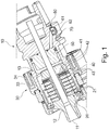
- Fig. 1 shows an exemplary structure of a tool holder 10 which can be used in the method according to the invention.
- a tool receiving section 11 for receiving a tool 90 (in Fig. 1 not shown, see Fig. 4 ).
- a tool 90 in Fig. 1 not shown, see Fig. 4 .
- several, for. B. six perforated disk-shaped first piezo elements 21 are arranged stacked, for example, which are connected to the tool receiving section 11 via a transmission section 12 and, for example, an ultrasonic transducer 20 (ultrasonic generator) for converting an electrical voltage into a mechanical vibration (e.g. with a frequency im Ultrasound area).
- the mechanical vibration of the first piezo elements 21 is transmitted to the tool 90 via the transmission section 12.
- the first piezo elements 21 can be designed, for example, as piezo ceramic disks with electrodes attached in between.
- the energy supply of the ultrasonic transducer 20 takes place, for example, via a transformer (first transformer), which, for example, on the machine side consists of a first pot core 31 and a primary winding 32 (in Fig. 1 not shown, see Fig. 4 ) and, for example, on the tool side consists of a second pot core 33 and a secondary coil 34, which are arranged, for example, as ring elements on the outside of the tool holder 10.
- first transformer which, for example, on the machine side consists of a first pot core 31 and a primary winding 32 (in Fig. 1 not shown, see Fig. 4 ) and, for example, on the tool side consists of a second pot core 33 and a secondary coil 34, which are arranged, for example, as ring elements on the outside of the tool holder 10.
- a perforated disk-shaped piezoelectric sensor element 40 is arranged, for example, which consists of a piezo element 41 and two contacts 42 and which is mechanically coupled to the first piezo elements 21, for example is electrically isolated from the first piezo elements 21 by an insulating element 43, which can consist of a ceramic perforated disk.
- the piezoelectric sensor element 40 is, for example, electrically isolated from a fastening element 13, for example a fastening nut, by a further insulation element 43.
- the fastening element 13 is used to fasten the piezoelectric sensor element 40 to the ultrasonic transducer 20 and to pretension the first piezo elements 21 because of the dynamic load.
- the first piezo elements 21 and the piezoelectric sensor element 40 are oriented in the same way, which on the one hand enables the generation and detection of the vibration in the same direction and on the other hand achieves a space-saving arrangement of the elements in the tool holder 10.
- the piezoelectric sensor element 40 converts the mechanical vibrations of the vibratory system, which consists of the tool 90, the transmission section 12, the ultrasonic transducer 20 and the piezoelectric Sensor element 40 is converted into a sensor signal, which is transmitted, for example, as an electrical voltage via a wire connection 50 from piezoelectric sensor element 40 through tool holder 10 to a transmitter element 61 and 62 on the outside of tool holder 10.
- the sensor signal is transmitted, for example, without contact to a machine-side receiver element 81 and 82 (in Fig. 1 not shown, see Fig. 4 ) transfer.
- the transmitter element 61 and 62 is part of a further transformer (second transformer) and consists, for example, of a first ferrite core 61 and a primary winding 62; the receiver element 81 and 82 is also part of the second transformer and consists of a second ferrite core 81 and a secondary winding 82.
- second transformer further transformer
- the sensor signal can be transmitted inductively from the tool holder 10 to a machine-side sensor signal evaluation device.
- the transmitter element 61 and 62 being designed as an LED and the receiver element 81 and 82 as a photodiode.
- the transmitter element 61 and 62 can be dimensioned and positioned in such a way that it fits into a bore 70 for a data chip for tool data according to the DIN 69893 standard.
- the tool holder 10 can be compared to a stationary part of the machine tool 1000 (in Fig. 1 not shown, see Fig. 4 ) be rotatable.
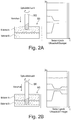
- Figure 2A shows schematically a machining process of a cutting tool 90 for ultrasonic machining on a workpiece WS, which consists of several layers of different materials (material A and material B).
- Figure 2B shows schematically the machining process after the cutting tool 90 has been dipped into the second material B for ultrasonic machining.
- the sensor signals of the piezo elements 21 change as shown in the diagram next to it.
- the change in material in the workpiece can be recognized and, preferably, the respective processing parameters such as rotational speed, cutting speed and / or feed of the tool, but also the vibration parameters such as parameters of the drive signals to the piezo elements 21 based on the recorded Sensor signals or adapted on the basis of the detection of the material change.
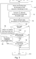
- Fig. 3 shows a flow chart of an embodiment of the method according to the invention.
- the tool 90 is operated on the basis of predetermined machining parameters.
- the ultrasonic vibration of the tool 90 is generated by the piezo elements 21, the signals from the piezoelectric sensor elements 40 such as amplitude, frequency and power being detected at the same time (step S4).
- step S5 a first evaluation of the detected sensor signals now takes place. It is z. B. checks whether the detected signals are essentially constant (in the range of a noise in the signal). If this is not the case, a temporal change t of the respective sensor signal is recorded in step S6, i.e. how quickly this signal changes, and at the same time the value change y of the respective sensor signal is recorded, i.e. how much or to what extent the corresponding signal changes changes.
- step S7 the change t over time is first compared with the previously established limit value t limit.
- the recorded change over time t is below the defined limit value tlimit, then in the next step S8 it is compared to what extent the value y has changed. For this purpose, the recorded change in value y is compared with the previously defined limit value y limit . If the detected change in value y is above the defined limit value y limit , the detected sensor signals speak for a change in material in the workpiece WS.
- the recorded values include a frequency of the vibration generated on the tool holder and / or a recorded power of the ultrasonic transducer 20.
- step S9 the specified machining parameters are adapted in step S9. This can include adapting or changing the feed rate of the tool and / or adapting or changing the cutting speed or rotation speed of the tool during the machining of the workpiece.
- the parameters can be adjusted as follows: After the sensor signals of the piezoelectric sensor elements 40 have been recorded, they are compared, for example, with data records which include sensor signals from correspondingly known materials that have already been recorded.
- These data sets can include resonance frequencies, for example of a tool-material combination or a damping capacity of a material, and are characteristic of every known material (like a kind of "fingerprint"). If a match is found, the present material is identified and the processing parameters can be adapted to the corresponding material on the basis of this.
- the type of material involved or the degree of hardness and damping capacity of this material can be estimated on the basis of the detected sensor signals and the processing parameters can be adapted on the basis of this. Material determinations are therefore also possible by way of example.
- processing parameters or processing parameter sets can already be specified for different materials or material layers of the workpiece, and when the change in the material of the workpiece is detected at the position of the tool tip of the tool, the processing parameters of the processing are set according to the various specified processing parameters or machining parameter sets adapted.
- step S8 Is however determined in step S8 that the change in value y of the corresponding sensor signal does not have a specified limit y cross exceeded, the process is continued with unchanged processing parameters.
- Fig. 4 shows schematically a device according to the invention with which the method according to the invention can be carried out.
- the device can be part of a machine tool 1000. Shown is a tool holder 10 with a piezoelectric sensor element 40, the structure of which is exemplified by that in FIG Fig. 1 tool holder 10 shown corresponds.
- the tool 90 for the ultrasonic machining of workpieces is received on the tool holder 10.
- a generator 120 outputs a work signal A1 as a drive signal for the piezo drive in the tool holder 10.
- the working signal A1 has the working frequency f1 and is transmitted without contact to the rotating tool holder 10 with the power P1 via the energy transfer device 30, which is designed as a transformer consisting of the primary winding 32 including the first pot core 31 and the secondary winding 34 including the second pot core 33.
- the generator also inputs 120 Test signal At a power Pt ⁇ P1, which is superimposed on the working signal A1 and whose frequency varies in a range around f1.
- the oscillatable system in the tool holder 10 is excited to oscillate, the frequency spectrum of which has essentially two frequencies.
- the piezoelectric sensor element 40 Due to the oscillation of the oscillatable system, the piezoelectric sensor element 40 also oscillates in the same way and thus generates an electrical sensor signal A2 which contains the information about the frequency spectrum of the oscillation.
- the sensor signal A2 is, for example, read out contactlessly by a reading device 130 from the rotating tool holder 10 and transmitted to an analysis device 140a via a further transformer, which consists of a primary winding 62 including a first ferrite core 61 and a secondary winding 82 including a second ferrite core 81.
- the analysis device 140a determines the frequencies contained in the frequency spectrum of A2, so that in a device for determining the resonance frequency 140b, which can be implemented as part of the analysis device 140a, the frequency of the largest peak in the spectrum (main frequency) can be assigned to the working frequency f1 and the frequency of the smaller peak in the spectrum (secondary frequency) can be assigned to the resonance frequency f2.
- the read-out device 130, the analysis device 140a and the device for determining the resonance frequency 140b can also be combined into two devices or implemented as a single device.
- the value of the determined resonance frequency f2 is transmitted to a first control device 150, which controls the generator 120 in such a way that the frequency f1 of the working signal A1 is adapted to the value of the resonance frequency f2.
- the value of the determined resonance frequency f2 can be transmitted to a second control device 160, which controls the generator 120 in such a way that the power P1, with which the work signal A1 is radiated into the tool holder 10, is increased to a power P1 ', so that even with an excitation with f1 ⁇ f2 the mechanical oscillation amplitude is reached that would be reached as the maximum amplitude with an excitation with the resonance frequency f2.
- the mechanical oscillation amplitude of the tool tip can be stabilized to a certain value, which has a positive effect on the precision during machining with the tool 90. If the oscillation amplitude is stabilized to the maximum possible value for a certain power, the efficiency of the workpiece machining also increases.
- a user of the device can control the first regulating device 150 and / or the second regulating device 160 via a user interface 170, so that the work signal A1 is only adapted on command of the user or when a specified condition occurs.
- the user can also specify that the working signal A1 is automatically adjusted at regular or irregular time intervals based on the last determined resonance frequency f2.
- the generator 120, the read-out device (or detection device) 130, the analysis device 140a and the first control device 150 can be combined to form a device 200 for outputting output signals and receiving input signals, a first output signal of this device 200 being the Working signal, a second output signal corresponds to the test signal At, and an input signal corresponds to the sensor signal A2.
- the vibration of the tool can be regulated at the respective resonance frequency of the vibration system. If the regulated resonance frequency or the associated power changes when the tool or its tool tip is at an interface between two materials, this can be used, according to exemplary embodiments of the invention, to detect a change in material.
- this can be the detection of an interface between two material layers in the workpiece, but this can also be an interface between the material of the workpiece, e.g. in the case of air pockets, cavities, bores, etc. in the workpiece or on the surface of the workpiece (air to workpiece surface) e.g. to detect the first contact with the workpiece.
Description
Die vorliegende Erfindung betrifft ein Verfahren zur Bearbeitung eines Werkstücks mittels eines Werkzeugs an einer numerisch gesteuerten Werkzeugmaschine. Des Weiteren betrifft die vorliegende Erfindung eine Vorrichtung und eine Werkzeugmaschine, auf diesen das vorgenannte Verfahren ausgeführt werden kann. Ferner betrifft die vorliegende Erfindung ein Computerprogramm-Produkt, mit diesem das vorgenannte Verfahren ausgeführt werden kann.The present invention relates to a method for machining a workpiece by means of a tool on a numerically controlled machine tool. The present invention also relates to a device and a machine tool on which the aforementioned method can be carried out. The present invention also relates to a computer program product with which the aforementioned method can be carried out.
Im Stand der Technik sind Werkzeugmaschinen bekannt, bei denen zum Beispiel bei einer spanenden Bearbeitung eines Werkstücks durch ein Werkzeug die Rotationsbewegung des Werkzeugs durch eine Ultraschallschwingung des Werkzeugs überlagert werden kann.Machine tools are known in the prior art in which, for example, when a workpiece is machined by a tool, the rotational movement of the tool can be superimposed by an ultrasonic vibration of the tool.
Bei einer solchen Werkzeugmaschine bilden ein Ultraschall-Erzeuger im Werkzeughalter, der die Ultraschallschwingung des Werkzeugs erzeugt, ein Schwingkörper und das im Werkzeughalter eingesetzte Werkzeug ein schwingungsfähiges System, das durch ein elektrisches Signal zu mechanischen Schwingungen angeregt wird, wobei man die größtmögliche mechanische Schwingungsamplitude erhält, wenn man das schwingungsfähige System mit seiner Resonanzfrequenz anregt.In such a machine tool, an ultrasonic generator in the tool holder that generates the ultrasonic vibration of the tool, a vibrating body and the tool inserted in the tool holder form a vibratory system that is converted to mechanical by an electrical signal Vibrations is excited, the greatest possible mechanical vibration amplitude being obtained when the vibratory system is excited with its resonance frequency.
Taucht das Werkzeug nun in das Werkstück ein, wird das schwingungsfähige System durch das Material des Werkstücks und der Reibung zwischen Werkstück und Werkzeug gedämpft und die Resonanzfrequenz verschiebt sich hin zu einer etwas geringeren Resonanzfrequenz. Dabei ist bekannt, dass sich mit steigender Dämpfung die Resonanzfrequenz weiter verschiebt.If the tool is now immersed in the workpiece, the vibratory system is dampened by the material of the workpiece and the friction between the workpiece and the tool, and the resonance frequency shifts to a slightly lower resonance frequency. It is known that the resonance frequency shifts further with increasing damping.
Nun tritt dabei nicht selten das Problem auf, dass es während der Bearbeitung zu deutlichen Schwankungen der Resonanzfrequenz kommt. Gleichzeitig bedeutet dies aber, dass sich das Dämpfungsvermögen des Materials, das gerade bearbeitet wird, geändert hat.The problem often arises that there are significant fluctuations in the resonance frequency during processing. At the same time, however, this means that the damping capacity of the material that is being processed has changed.
Grund dafür können Materialänderungen innerhalb des Werkstücks sein, da trotz eines augenscheinlich homogenen Materials des Werkstücks eine Inhomogenität (wie z.B. Korngrenzen oder Einschlüsse von Fremdmaterial etc.) auftreten kann. Aufgrund solcher Materialänderungen kann es erforderlich sein, die vorgegebenen Bearbeitungsparameter, mit denen das Werkzeug das Werkstück bearbeitet, auf das jeweilige Material und seine Eigenschaften anzupassen.The reason for this can be material changes within the workpiece, as inhomogeneity (such as grain boundaries or inclusions of foreign material etc.) can occur despite an apparently homogeneous material of the workpiece. As a result of such material changes, it may be necessary to adapt the specified processing parameters with which the tool processes the workpiece to the respective material and its properties.
Aber auch geometrische Änderungen des Werkstücks, wie zum Beispiel Bohrungen oder Ausnehmungen, stellen eine Art Inhomogenität des Materials des Werkstücks dar, die gegebenenfalls Einfluss auf die vorgegebenen Bearbeitungsparameter hat.However, geometrical changes in the workpiece, such as bores or recesses, represent a type of inhomogeneity in the material of the workpiece, which may have an influence on the specified processing parameters.
Um zu bestimmen, wann eine Materialänderung während der Bearbeitung des Werkstücks vorliegt, sind bereits Messsysteme bekannt, die das Prinzip des Körperschalls nutzen. Dabei wird, meist mit beträchtlichem Abstand zum Werkstück, ein entsprechender Körperschall-Sensor am Maschinenrahmen angebracht, der die aufkommenden Schwingungen misst und daraus ein Messsignal generiert. Eine Steuereinheit wertet diese Messsignale aus und kann bei einer entsprechenden Feststellung von Messsignalabweichungen während der Bearbeitung die vorgegebenen Bearbeitungsparameter ändern.In order to determine when a material change occurs during the machining of the workpiece, measuring systems are already known that use the principle of structure-borne noise. A corresponding structure-borne noise sensor is attached to the machine frame, usually at a considerable distance from the workpiece, which measures the vibrations and generates a measurement signal from them. A control unit evaluates these measurement signals and, if a corresponding Detection of measurement signal deviations during processing Change the specified processing parameters.
Doch ergibt sich daraus der Nachteil, dass aufgrund des weiter entfernt angeordneten Messsensors die aufkommenden Schwingungen nicht ausschließlich auf die Änderung des Materials innerhalb des Werkstücks zurückzuführen sind. Diese Schwingungen können durch Schwingungen aus der Umgebung beeinflusst bzw. überlagert werden. Dies kann zu Fehlauswertungen des Messsignals und im Ergebnis zu einer fehlerhaften Anpassung der Bearbeitungsparameter führen.However, this results in the disadvantage that, because the measuring sensor is arranged further away, the vibrations that occur are not exclusively due to the change in the material within the workpiece. These vibrations can be influenced or superimposed by vibrations from the environment. This can lead to incorrect evaluations of the measurement signal and, as a result, to incorrect adaptation of the machining parameters.
Aus diesem Grund ist es wichtig, eine Änderung des Materials während der Bearbeitung des Werkstücks so nah wie möglich am Werkstück selbst zu erfassen, um eine Überlagerung von äußeren Schwingungen weitestgehend zu vermeiden.For this reason, it is important to detect a change in the material during the machining of the workpiece as close as possible to the workpiece itself in order to largely avoid superimposition of external vibrations.
- Steuern einer Relativbewegung des Werkzeugs relativ zu dem Werkstück zum Bearbeiten des Werkstücks, - Erzeugen einer Schwingung des Werkzeugs mittels eines Schwingung-Erzeugers,
- Erfassen zumindest eines aus dem Schwingung-Erzeuger ausgegebenen Sensorsignals, und
- Erkennen einer Materialänderung am Werkstück während des Steuerns der Relativbewegung des Werkzeugs relativ zu dem Werkstück auf Basis des zumindest einen aus dem Schwingung-Erzeuger ausgegebenen Sensorsignals, wobei das Steuern der Relativbewegung des Werkzeugs relativ zu dem Werkstück auf Basis vorgegebener Bearbeitungsparameter durchgeführt wird, wobei das Verfahren weiterhin umfasst: - Anpassen der vorgegebenen Bearbeitungsparameter, wenn eine Materialänderung am Werkstück auf Basis des zumindest einen aus dem Ultraschall-Erzeuger ausgegebenen Sensorsignals erkannt wird, und - Steuern der Relativbewegung des Werkzeugs relativ zu dem Werkstück auf Basis der angepassten Bearbeitungsparameter, - wobei das Anpassen von Bearbeitungsparametern ferner zumindest ein Anpassen des Schwingung-Erzeugers umfasst.
- Controlling a relative movement of the tool relative to the workpiece for machining the workpiece, generating a vibration of the tool by means of a vibration generator,
- Detecting at least one sensor signal output from the vibration generator, and
- Detection of a material change on the workpiece during the control of the relative movement of the tool relative to the workpiece on the basis of the at least one sensor signal output from the vibration generator, the control of the relative movement of the tool relative to the workpiece being carried out on the basis of predetermined machining parameters, the method furthermore comprises: adjusting the specified machining parameters when a material change on the workpiece is detected on the basis of the at least one sensor signal output from the ultrasonic generator, and controlling the relative movement of the tool relative to the workpiece based on the adjusted machining parameters, the adjusting of processing parameters further comprises at least one adaptation of the vibration generator.
Eine Aufgabe der vorliegenden Erfindung ist es daher, ein Verfahren zur Bearbeitung eines Werkstücks an einer numerisch gesteuerten Werkzeugmaschine bereitzustellen, mit dem die obigen Probleme vermieden werden.It is therefore an object of the present invention to provide a method for machining a workpiece on a numerically controlled machine tool with which the above problems are avoided.
Des Weiteren ist es Aufgabe der vorliegenden Erfindung, eine Vorrichtung, eine Werkzeugmaschine und ein Computerprogramm-Produkt bereitzustellen, mit dem das erfindungsgemäße Verfahren ausgeführt werden kann.A further object of the present invention is to provide a device, a machine tool and a computer program product with which the method according to the invention can be carried out.
Diese Aufgaben werden gelöst durch ein Verfahren nach Anspruch 1, eine Vorrichtung nach Anspruch 8, eine Werkzeugmaschine nach Anspruch 9 und ein Computerprogramm-Produkt nach Anspruch 10. Die abhängigen Ansprüche beziehen sich auf vorteilhafte Ausführungsbeispiele des erfindungsgemäßen Verfahrens.These objects are achieved by a method according to
Das erfindungsgemäße Verfahren zur Bearbeitung eines Werkstücks an einei numerisch gesteuerten Werkzeugmaschine mittels eines Werkzeugs umfasst die Schritte Steuern einer Relativbewegung des Werkzeugs relativ zu dem Werkstück zum Bearbeiten des Werkstücks, Erzeugen einer Ultraschall-Schwingung des Werkzeugs mittels eines Ultraschall-Erzeugers, Erfassen zumindest eines aus dem Ultraschall-Erzeuger ausgegebenen Sensorsignals, und Erkennen einer Materialänderung am Werkstück während des Steuerns der Relativbewegung des Werkzeugs relativ zu dem Werkstück auf Basis des zumindest einen aus dem Ultraschall-Erzeuger ausgegebenen Sensorsignals.The method according to the invention for machining a workpiece on a numerically controlled machine tool by means of a tool comprises the steps of controlling a relative movement of the tool relative to the workpiece for machining the workpiece, generating an ultrasonic vibration of the tool by means of an ultrasound generator, detecting at least one sensor signal output from the ultrasound generator, and recognizing a change in material on the workpiece while controlling the relative movement of the tool relative to the workpiece on the basis of the at least one sensor signal output from the ultrasound generator.
Der Ultraschall-Erzeuger dient neben der Anregung des Werkzeugs zur Schwingung auch gleichzeitig als Sensor für das Erfassen der Resonanzfrequenz des schwingungsfähigen Systems. Der Vorteil dieses Verfahrens liegt darin, dass der Ultraschall-Erzeuger in unmittelbarer Nähe zum Werkzeug und in direkter Linie mit Werkzeug und Werkstück angeordnet ist. Somit kann die Resonanzfrequenz und somit das Dämpfungsvermögen des jeweils vorliegenden Materials sehr nah am Werkstück erfasst werden, was wiederum den Einfluss von äußeren Schwingungsquellen im erheblichen Maße reduziert.In addition to stimulating the tool to vibrate, the ultrasonic generator also serves as a sensor for recording the resonance frequency of the vibratory system. The advantage of this method is that the ultrasonic generator is arranged in close proximity to the tool and in direct line with the tool and workpiece. The resonance frequency and thus the damping capacity of the material present in each case can thus be recorded very close to the workpiece, which in turn significantly reduces the influence of external vibration sources.
Zusätzlich kann eine Änderung des Materials im Werkstück punktgenau am Übergang von einem Material zum anderen Material erkannt werden und entsprechend diese Information an die Steuerung des Werkzeugs übertragen werden.In addition, a change in the material in the workpiece can be recognized with pinpoint accuracy at the transition from one material to the other and this information can be transferred to the tool control accordingly.
Das erfindungsgemäße Verfahren ist im Anspruch 1 definiert.The method according to the invention is defined in
Die vorgegebenen Bearbeitungsparameter können in Abhängigkeit der Sensorsignale des Ultraschall-Erzeugers gesteuert werden, um entsprechend die jeweiligen Materialien mit den dafür erforderlichen Parametern zu bearbeiten.The specified processing parameters can be controlled as a function of the sensor signals of the ultrasonic generator in order to process the respective materials with the parameters required for this.
Ein zusätzlicher Vorteil offenbart sich darin, dass sich durch die weitest gehende Reduzierung von Einflüssen der äußeren Schwingungsquellen für jedes Material eine Art "Fingerabdruck" (z.B. eine bestimmte gedämpfte Resonanzfrequenz des schwingungsfähigen Systems und/oder ein bestimmtes Dämpfungsvermögen des Materials) generieren und abspeichern lässt.An additional advantage is revealed in the fact that, due to the greatest possible reduction in the effects of external vibration sources, one type of "Fingerprint" (eg a certain damped resonance frequency of the oscillating system and / or a certain damping capacity of the material) can be generated and stored.
Dies kann zum Beispiel bei Verbundwerkstoffen von großem Vorteil sein, da hier oftmals sehr unterschiedliche Materialien (CFK mit Titan/Aluminium) in einem Werkstück miteinander kombiniert sind. Daraus ergibt sich der Wunsch bzw. der Bedarf, die Bearbeitungsparameter für jedes Material entsprechend anzupassen. Oftmals wurden im Vorfeld der Bearbeitung die jeweiligen Schichtdicken der Materialien auf Basis einer fehlerfreien Einspannung einprogrammiert, aufgrund dieser die Bearbeitungsparameter während der Bearbeitung dann angepasst wurden.This can be of great advantage with composite materials, for example, as very different materials (CFRP with titanium / aluminum) are often combined in one workpiece. This results in the desire or need to adapt the processing parameters accordingly for each material. Often the respective layer thicknesses of the materials were programmed in advance of the machining on the basis of error-free clamping, on the basis of which the machining parameters were then adjusted during the machining.
Da aber Schwankungen der Schichtdicken sowie Unregelmäßigkeiten in der Einspannung des Werkstücks zwangsweise vorhanden sind, wurde immer ein Teil eines der Materialien mit ungeeigneten Bearbeitungsparametern bearbeitet. Mithilfe des Verfahrens ist es nun möglich, punktgenau eine Materialänderung im Werkstück zu erkennen und daraufhin die Bearbeitungsparameter auf das jeweilige Material anzupassen.However, since fluctuations in the layer thickness and irregularities in the clamping of the workpiece are inevitable, part of one of the materials was always processed with unsuitable processing parameters. With the help of the process, it is now possible to precisely identify a material change in the workpiece and then to adapt the processing parameters to the respective material.
Eine weitere vorteilhafte Weiterbildung des Verfahrens liegt darin, dass das Werkstück zumindest zwei unterschiedliche Materialbereiche umfasst, und wobei im Schritt Erkennen einer Materialänderung am Werkstück ein Übergang des Werkzeugs von einem Materialbereich in den anderen Materialbereich des Werkstücks erkannt wird.A further advantageous development of the method is that the workpiece comprises at least two different material areas, and a transition of the tool from one material area to the other material area of the workpiece is detected in the step of detecting a material change on the workpiece.
Das oben beschriebene Verfahren ist dabei nicht auf eine begrenzte Anzahl an Materialänderungen limitiert, sondern kann unbegrenzt Materialänderungen erkennen, aufgrund dessen die Bearbeitungsparameter des Werkzeugs angepasst werden können.The method described above is not limited to a limited number of material changes, but can recognize unlimited material changes, based on which the machining parameters of the tool can be adjusted.
Zusätzlich lässt sich das Verfahren so vorteilhaft weiterbilden, dass das Werkstück einen Verbundwerkstoff, insbesondere einen Kohlefaser verstärkten Verbundwerkstoff, und/oder einen Glas- und/oder Keramikwerkstoff umfasst.In addition, the method can be so advantageously developed that the workpiece comprises a composite material, in particular a carbon fiber reinforced composite material, and / or a glass and / or ceramic material.
Eine Beschränkung des Verfahrens auf bestimmte Werkstoffe existiert nicht. Vorteilhafterweise hinterlassen auch Verbundwerkstoffe, Glas und Keramik einen "Fingerabdruck" (charakteristische/s Resonanzfrequenzen und/oder Dämpfungsvermögen), der für das Anpassen der vorgegebenen Bearbeitungsparameter abgespeichert und verwendet werden kann.The method is not restricted to specific materials. Composite materials, glass and ceramics also advantageously leave behind "Fingerprint" (characteristic resonance frequencies and / or damping capacity), which can be stored and used for adapting the specified processing parameters.
Das Verfahren kann vorteilhaft so weitergebildet werden, dass die Materialbereiche Schichten unterschiedlicher Materialien oder Materialbeschaffenheiten sind, oder dass die Materialbereiche Materialeinschlüsse im Werkstück sind, oder dass die Materialbereiche Bohrungen und/oder Ausnehmungen im Werkstück sind.The method can advantageously be developed in such a way that the material areas are layers of different materials or material properties, or that the material areas are material inclusions in the workpiece, or that the material areas are bores and / or recesses in the workpiece.
Materialänderungen bzw. Materialbereiche können sich nicht nur durch verschiedene Materialeigenschaften unterscheiden, sie können auch durch geometrische Änderungen des Werkstücks gekennzeichnet sein.Material changes or material areas can differ not only through different material properties, they can also be characterized by geometrical changes in the workpiece.
Zum Beispiel kann es während der Bearbeitung dazu kommen, dass sich das Werkzeug vom Material des Werkstücks in eine Bohrung des Werkstücks (eventuell auch nur teilweise) hinein arbeitet. Auch dann kommt es zu einer Änderung der Resonanzfrequenz bzw. des Dämpfungsvermögens des Werkstücks an dieser Stelle und somit zu einer Art Materialänderung. Auch hier kann es dann wiederum erwünscht sein, die vorgegebenen Bearbeitungsparameter anzupassen.For example, during machining, the tool may work its way from the material of the workpiece into a hole in the workpiece (possibly only partially). Then, too, there is a change in the resonance frequency or the damping capacity of the workpiece at this point and thus in a type of material change. Here, too, it can then again be desirable to adapt the specified machining parameters.
Das Verfahren kann vorteilhafterweise so weitergebildet werden, dass im Schritt Erkennen einer Materialänderung am Werkstück ein Kontakt des Werkzeugs mit einer Oberfläche des Werkstücks erkannt wird (d.h. zum Beispiel eine Materialänderung von Luft zu Oberfläche des Werkstücks, im Gegensatz zu einer Materialänderung im Werkstück).The method can advantageously be developed in such a way that in the step of detecting a material change on the workpiece, contact of the tool with a surface of the workpiece is detected (i.e., for example, a material change from air to the surface of the workpiece, as opposed to a material change in the workpiece).
Dies hat einen besonders großen Vorteil, da ein sehr schnelles Anfahren an das Werkstück gewährleistet werden kann und dabei die Bearbeitungszeit verkürzt werden kann. Dies ist insbesondere bei sehr stark bruchgefährdeten Materialen wie Glas oder Keramik von Vorteil.This has a particularly great advantage, since a very quick approach to the workpiece can be guaranteed and the machining time can be shortened. This is particularly advantageous in the case of materials that are very susceptible to breakage, such as glass or ceramics.
Das Anfahren von Werkstücke aus solchen Materialien mit dem Werkzeug erfolgt bis dato nur bis zu einem vorgegebenen Sicherheitsabstand in hohem Tempo, danach wird mit den vorgegebenen Bearbeitungsparametern, die vergleichsweise langsam sind, weitergearbeitet. Wird der Sicherheitsabstand zu großzügig gewählt, wird Bearbeitungszeit unnötig verschenkt.To date, the tool has only approached workpieces made of such materials up to a specified safety distance at high speed, after which the specified processing parameters, which are comparatively slow, are continued working. If the safety distance is chosen too generously, processing time is wasted unnecessarily.
Durch die Erkennung der Materialänderung (z.B. von Luft zur Oberfläche des Werkstücks) kann das Werkzeug bis zur tatsächlichen Grenze von Luft zu Werkstück mit hohem Tempo bewegt werden, bevor eine Anpassung der vorgegebenen Bearbeitungsparameter auf das entsprechende Material durchgeführt wird.By detecting the change in material (e.g. from air to the surface of the workpiece), the tool can be moved at high speed up to the actual limit from air to workpiece before the specified machining parameters are adapted to the corresponding material.
Im Schritt Erkennen einer Materialänderung am Werkstück wird ferner eine zeitliche Änderung und gleichzeitig eine Wertänderung eines oder mehrerer Parameter des Sensorsignals des Ultraschall-Erzeugers erfasst.In the step of recognizing a change in material on the workpiece, a change over time and, at the same time, a change in value of one or more parameters of the sensor signal of the ultrasonic generator are recorded.
Der Vorteil dieses Schrittes liegt darin, dass eine Anderung der Resonanzfrequenz des schwingungsfähigen Systems auch andere Gründe haben kann als eine Materialänderung des Werkstoffs. Durch den Bearbeitungsprozess entstehen zum Teil große Mengen an Wärme, die das Werkzeug wie aber auch das Werkstück teils stark erhitzen.The advantage of this step is that a change in the resonance frequency of the oscillatable system can also have reasons other than a change in the material. During the machining process, large amounts of heat are generated in some cases, which in some cases heat the tool as well as the workpiece.
Auch dieses Beeinflusst die Resonanzfrequenz des schwingungsfähigen Systems im erheblichen Maße. Allerdings besteht die Möglichkeit, diese Einflüsse von denen einer Materialänderung zu unterscheiden.This also influences the resonance frequency of the oscillatable system to a considerable extent. However, it is possible to differentiate these influences from those of a material change.
Eine Änderung der Resonanzfrequenz des schwingungsfähigen Systems aufgrund von Erwärmung des Werkzeugs und/oder Werkstücks erfolgt kontinuierlich und über einen vergleichsweise langen Zeitraum. Dies steht im Gegensatz zum Auftreten einer Materialänderung, die sich in einer sprunghaften Änderung der Resonanzfrequenz bemerkbar macht.A change in the resonance frequency of the vibratory system due to heating of the tool and / or workpiece takes place continuously and over a comparatively long period of time. This is in contrast to the occurrence of a material change, which is noticeable in a sudden change in the resonance frequency.
Neben der zeitlichen Anderung eines oder mehrerer Parameter des Sensorsignals wird auch die Wertänderung des/der entsprechenden Parameter des Sensorsignals erfasst. Jedes Sensorsignal kann ein Rauschen aufweisen, was sich unter anderem in zeitlich abrupten, aber sehr geringen Änderungen des Parameters bemerkbar macht.In addition to the change in one or more parameters of the sensor signal over time, the change in value of the corresponding parameter (s) of the sensor signal is also recorded. Every sensor signal can be a noise which is noticeable, among other things, in temporally abrupt but very small changes in the parameter.
Daher wird neben dem Erfassen der zeitlichen Anderung auch die Wertänderung der entsprechenden Parameter erfasst. Diese Kombination bildet die Grundlage für eine zuverlässige Aussage über das Vorhandensein einer Materialänderung.Therefore, in addition to recording the change over time, the change in value of the corresponding parameters is also recorded. This combination forms the basis for a reliable statement about the existence of a material change.
Das Verfahren weist den folgenden Schritt auf: Feststellen, ob die zeitliche Änderung und die Wertänderung des mindestens einen Sensorsignals des Ultraschall-Erzeugers entsprechend eine vorbestimmte Änderungszeit unterschreitet und gleichzeitig einen vorbestimmten Änderungswert überschreitet.The method has the following step: determining whether the change over time and the change in value of the at least one sensor signal of the ultrasonic generator falls below a predetermined change time and at the same time exceeds a predetermined change value.
Neben dem Erfassen der zeitlichen Änderung und der Wertänderung der Parameter des Sensorsignals ist es erforderlich, Grenzwerte für die jeweiligen Änderungen im Sensorsignal festzulegen.In addition to recording the change over time and the change in value of the parameters of the sensor signal, it is necessary to define limit values for the respective changes in the sensor signal.
Auf Basis derer kann ein Auftreten einer Materialänderung von anderen Faktoren (wie eben eine Temperaturänderung an Werkstück/Werkzeug) weitestgehend unterschieden werden, in dem ein Über- bzw. Unterschreiten der Grenzwerte festgestellt werden kann.On the basis of this, the occurrence of a material change can be differentiated as far as possible from other factors (such as a temperature change on the workpiece / tool) by determining whether the limit values have been exceeded or fallen below.
Die vorgegebenen Bearbeitungsparameter werden angepasst, wenn die zeitliche Änderung und die Wertänderung des mindestens einen Sensorsignals des Ultraschall-Erzeugers entsprechend die vorbestimmte Änderungszeit unterschreitet und gleichzeitig den vorbestimmten Änderungswert überschreitet.The predetermined processing parameters are adapted if the change over time and the change in value of the at least one sensor signal of the ultrasonic generator correspondingly fall below the predetermined change time and at the same time exceed the predetermined change value.
Durch das zusätzliche Überprüfen der zeitlichen Änderung und der Wertänderung des mindestens einen Parameters des Sensorsignals kann eine zuverlässigere Aussage über das Vorhandensein einer Materialänderung getroffen werden. Das Risiko, eine vermeintlich vorhandene Materialänderung aufgrund von Temperaturveränderungen des Werkzeugs und Werkstücks zu erfassen, kann mittels dieser zusätzlichen Überprüfung deutlich minimiert werden.By additionally checking the change over time and the change in value of the at least one parameter of the sensor signal, a more reliable statement can be made about the presence of a change in material. The risk one Detecting supposedly existing material changes due to temperature changes of the tool and workpiece can be significantly minimized by means of this additional check.
Eine weitere vorteilhafte Weiterbildung dieses Verfahrens liegt darin, dass das Anpassen von Bearbeitungsparametern zumindest ein Anpassen einer Drehzahl bzw. Schnittgeschwindigkeit und/oder eines Vorschubs der Relativbewegung des Werkzeugs umfasst. Vorzugsweise sind die vorgegebenen Bearbeitungsparameter eines oder mehreres aus einer Vorschubgeschwindigkeit des Werkzeugs bei der Werkstückbearbeitung, einer Schnittgeschwindigkeit der spanenden Schneiden bzw. Abschnitte des Werkzeugs und der Drehzahl des Werkzeugs (z.B. eine Spindeldrehzahl einer das Werkzeug antreibenden Arbeitsspindel einer Werkzeugmaschine).A further advantageous development of this method is that the adaptation of machining parameters includes at least an adaptation of a rotational speed or cutting speed and / or an advance of the relative movement of the tool. The predetermined machining parameters are preferably one or more of a feed speed of the tool when machining the workpiece, a cutting speed of the cutting edges or sections of the tool and the speed of the tool (e.g. a spindle speed of a work spindle of a machine tool that drives the tool).
Somit können aufgrund einer detektierten Materialänderung bestimmte vorgegebene Bearbeitungsparameter angepasst werden, zum Beispiel die des Hauptantriebs (z.B. Spindelantrieb) für die Rotation des Werkzeugs und/oder des Antriebs für den Vorschub des Werkzeugs.As a result of a detected change in the material, certain specified processing parameters can be adapted, for example those of the main drive (e.g. spindle drive) for rotating the tool and / or the drive for advancing the tool.
Weiterhin ist es eine vorteilhafte Weiterbildung des Verfahrens, wenn das Anpassen von Bearbeitungsparametern ferner zumindest ein Anpassen einer Frequenz und/oder einer Leistung des Ultraschall-Erzeugers umfasst.Furthermore, it is an advantageous development of the method if the adaptation of processing parameters further includes at least an adaptation of a frequency and / or a power of the ultrasound generator.
Nicht nur die Antriebe für die Werkzeugrotation und den Vorschub des Werkzeugs können auf die entsprechende Materialänderung angepasst werden, auch der Ultraschall-Erzeuger selbst kann den Erfordernissen des Materials angepasst werden. Dies kann zum Beispiel die Frequenz, die Amplitude und die Leistung des Ultraschall-Erzeugers umfassen.Not only the drives for the tool rotation and the feed of the tool can be adapted to the corresponding change in material, the ultrasonic generator itself can also be adapted to the requirements of the material. This can include, for example, the frequency, the amplitude and the power of the ultrasound generator.
Das Verfahren kann vorteilhafterweise so weitergebildet werden, dass der Ultraschall-Erzeuger ein Piezo-Aktor-System ist.The method can advantageously be developed in such a way that the ultrasonic generator is a piezo actuator system.
Der Vorteil eines Piezo-Aktor-Systems liegt darin, dass extrem hohe Frequenzen (Ultraschall) durch das sehr hohe dynamische Verhalten der Piezokristalle erzeugt werden können, wobei gleichzeitig die Piezo-Elemente eine hohe Robustheit und gutes lineares Steuerungsverhalten aufweisen.The advantage of a piezo actuator system is that extremely high frequencies (ultrasound) can be generated by the very high dynamic behavior of the piezo crystals, while the piezo elements are also extremely robust and have good linear control behavior.
Das Verfahren kann vorteilhafterweise so weitergebildet werden, dass das Werkzeug zumindest eine geometrisch bestimmte Schneide oder zumindest eine geometrisch unbestimmte Schneide aufweist.The method can advantageously be developed in such a way that the tool has at least one geometrically determined cutting edge or at least one geometrically undefined cutting edge.
Das Verfahren ist weder auf bestimmte Materialien/Werkstoffe noch auf bestimmte Werkzeuge beschränkt und kann daher in einem sehr breiten Anwendungsspektrum Verwendung finden.The process is not restricted to specific materials or specific tools and can therefore be used in a very wide range of applications.
Die erfindungsgemäße Vorrichtung ist im Anspruch 8 definiert.The device according to the invention is defined in claim 8.
Die erfindungsgemäße Werkzeugmaschine zur Bearbeitung eines Werkstücks mittels eines Werkzeugs umfasst dabei folgendes: eine Steuereinheit zum Steuern einer Relativbewegung des Werkzeugs relativ zu dem Werkstück zum Bearbeiten des Werkstücks, einen Ultraschall-Erzeuger zum Erzeugen einer Ultraschall-Schwingung des Werkzeugs, und eine Erfassungseinheit zum Erfassen zumindest eines aus dem Ultraschall-Erzeuger ausgegebenen Sensorsignals.The machine tool according to the invention for machining a workpiece by means of a tool comprises the following: a control unit for controlling a relative movement of the tool relative to the workpiece for machining the workpiece, an ultrasonic generator for generating an ultrasonic vibration of the tool, and a detection unit for detecting at least a sensor signal output from the ultrasonic generator.
Somit ist es möglich, das vorher beschriebene Verfahren in einer Steuervorrichtung bzw. einer Werkzeugmaschine zu implementieren und damit bereits existierenden Werkzeugmaschinen die Nutzung des Verfahrens zu ermöglichen. Dies kann mit vorbeschriebenen bevorzugten Aspekten des Verfahrens kombiniert werden.It is thus possible to implement the previously described method in a control device or a machine tool and thus to enable existing machine tools to use the method. This can be combined with the above-described preferred aspects of the method.
Das erfindungsgemäße Computerprogramm-Produkt weist dabei folgendes auf: ein auf einem computerlesbaren Datenspeichermedium gespeichertes Computerprogramm, das ausführbar an einer numerischen Steuereinheit einer numerisch gesteuerten Werkzeugmaschine oder in einem mit einer Steuereinheit einer numerisch gesteuerten Werkzeugmaschine verbundenen Computer ist und dafür eingerichtet ist, das weiter oben beschriebene Verfahren auszuführen.The computer program product according to the invention has the following: a computer program stored on a computer-readable data storage medium, which can be executed on a numerical control unit of a numerically controlled machine tool or in a computer connected to a control unit of a numerically controlled machine tool and is set up to carry out the method described above.
Dadurch kann das Verfahren in eine bestehende Steuerungssoftware einer Werkzeugmaschine implementiert und ausgeführt werden. Dies kann mit vorbeschriebenen bevorzugten Aspekten des Verfahrens kombiniert werden.As a result, the method can be implemented and executed in the existing control software of a machine tool. This can be combined with the above-described preferred aspects of the method.
Im folgenden werden weitere, zur Anwendung des erfindungsgemäßen Verfahrens bzw. von beispielhaften Ausführungen desselben vorteilhaft nutzbare Aspekte beschrieben.In the following, further aspects which can be used advantageously for the application of the method according to the invention or exemplary embodiments thereof are described.
Eine Vorrichtung zur Erzeugung einer Ultraschallschwingung eines Werkzeugs zur spanenden Ultraschall-Bearbeitung eines Werkstücks und zur Messung von Ultraschall-Schwingungsparametern der Ultraschallschwingung des Werkzeugs, insbesondere bevorzugt zum Erkennen einer Materialänderung im bzw. am Werkstück während der Bearbeitung, kann aufweisen: einen Werkzeughalter zur Aufnahme des Werkzeugs, einen Ultraschallwandler (Ultraschall-Erzeuger) im Werkzeughalter zum Erzeugen der Ultraschallschwingung des Werkzeugs, eine Sensoreinrichtung im Werkzeughalter zum Erzeugen eines Sensorsignals basierend auf der Ultraschallschwingung des Werkzeugs, und eine Sensorsignal-Auswertevorrichtung zum Auswerten des Sensorsignals. Die Auswertevorrichtung kann dazu eingerichtet sein, auf Basis einer Auswertung des Sensorsignals eine Materialänderung im Werkstück während der Bearbeitung gemäß einem der vorstehenden Aspekte auszuführen.A device for generating an ultrasonic vibration of a tool for ultrasonic cutting machining of a workpiece and for measuring ultrasonic vibration parameters of the ultrasonic vibration of the tool, particularly preferably for detecting a material change in or on the workpiece during machining, can have: a tool holder for receiving the Tool, an ultrasonic transducer (ultrasonic generator) in the tool holder for generating the ultrasonic vibration of the tool, a sensor device in the tool holder for generating a sensor signal based on the ultrasonic vibration of the tool, and a sensor signal evaluation device for evaluating the sensor signal. The evaluation device can be set up to carry out a material change in the workpiece during processing in accordance with one of the above aspects on the basis of an evaluation of the sensor signal.
Beispielsweise kann der Ultraschallwandler (Ultraschall-Erzeuger) als ein oder mehrere Piezo-Elemente ausgebildet sein, die auch als Sensoreinrichtung fungieren.For example, the ultrasonic transducer (ultrasonic generator) can be designed as one or more piezo elements, which also function as a sensor device.
Somit wird eine Vorrichtung bereitgestellt, mit der eine Ultraschallschwingung des Werkzeugs erzeugt und parallel dazu eine direkte Messung der Ultraschall-Schwingungsparameter des schwingenden Werkzeugs durchgeführt werden kann, insbesondere bevorzugt zum Erkennen einer Materialänderung im bzw. am Werkstück während der Bearbeitung. Es kann ein elektrisches Sensorsignal erzeugt werden, das einen direkten Rückschluss auf die mechanische Schwingung erlaubt. Das Sensorsignal kann zu einem oder mehreren Zeitpunkten oder in einem Zeitraum während der Bearbeitung erzeugt werden und ist somit ständig aktualisierbar. Dies ermöglicht eine Überwachung der Schwingung bzw. die Detektion von Veränderungen der Schwingungsparameter wie beispielsweise einer Verminderung der Schwingungsamplitude oder einer Änderung der Resonanzfrequenz, insbesondere bevorzugt zum Erkennen einer Materialänderung im bzw. am Werkstück während der Bearbeitung.Thus, a device is provided with which an ultrasonic vibration of the tool can be generated and, in parallel, a direct measurement of the ultrasonic vibration parameters of the vibrating tool can be carried out, particularly preferably for detecting a material change in or on the workpiece during machining. An electrical sensor signal can be generated that allows direct conclusions to be drawn about the mechanical vibration. The sensor signal can be generated at one or more times or in a period of time during processing and can therefore be continuously updated. This enables the vibration to be monitored or changes in the vibration parameters such as a reduction in the vibration amplitude or a change in the resonance frequency to be detected, particularly preferably for the detection of a material change in or on the workpiece during machining.
Vorzugsweise umfasst die Sensoreinrichtung ein oder mehrere piezoelektrische Sensorelemente und das Sensorsignal ist bevorzugt eine durch die Ultraschallschwingung des Werkzeugs bewirkte elektrische Spannung.The sensor device preferably comprises one or more piezoelectric sensor elements and the sensor signal is preferably an electrical voltage caused by the ultrasonic vibration of the tool.
Vorzugsweise ist der Werkzeughalter rotierbar und weist die Vorrichtung ein mit der Sensoreinrichtung verbundenes Senderelement im Werkzeughalter und ein von dem Senderelement beabstandetes Empfängerelement zur berührungslosen Übertragung des Sensorsignals von dem Senderelement zu dem Empfängerelement auf.The tool holder is preferably rotatable and the device has a transmitter element connected to the sensor device in the tool holder and a receiver element spaced from the transmitter element for contactless transmission of the sensor signal from the transmitter element to the receiver element.
Dabei kann das Empfängerelement beispielsweise außerhalb des Werkzeughalters in einem ortsfesten Teil einer Werkzeugmaschine mit der erfindungsgemäßen Vorrichtung angeordnet sein. Mit Hilfe des vom Senderelement beabstandeten maschinenseitigen Empfängerelements kann das Sensorsignal aus dem rotierbaren Werkzeughalter zur Auswertung herausgeführt werden.The receiver element can for example be arranged outside the tool holder in a stationary part of a machine tool with the device according to the invention. With the aid of the receiver element on the machine side, which is spaced apart from the transmitter element, the sensor signal can be fed out of the rotatable tool holder for evaluation.
Vorzugsweise weist die Sensoreinrichtung ein Isolierungselement zur elektrischen Isolation von dem Ultraschallwandler auf und weist die Vorrichtung eine Energieübertragungsvorrichtung zum Übertragen von Energie in den Werkzeughalter zur Energieversorgung des Ultraschallwandlers auf, wobei die Energieübertragungsvorrichtung von dem Senderelement und von dem Empfängerelement elektrisch isoliert ist.The sensor device preferably has an insulation element for electrical insulation from the ultrasonic transducer and the device has an energy transfer device for transferring energy into the tool holder for supplying energy to the ultrasonic transducer, the energy transfer device being electrically isolated from the transmitter element and from the receiver element.
Durch die elektrische Entkopplung der Sensoreinrichtung und der Sensorsignalbahn im Werkzeughalter vom Ultraschallschwingungsantrieb und dessen Energieversorgung erfolgt die Detektion der Werkzeugschwingung vollkommen unabhängig von der Erzeugung der Werkzeugschwingung, wodurch eine Verfälschung des Sensorsignals verhindert wird.Due to the electrical decoupling of the sensor device and the sensor signal path in the tool holder from the ultrasonic vibration drive and its energy supply, the tool vibration is completely detected independent of the generation of the tool vibration, which prevents corruption of the sensor signal.
Vorzugsweise sind das Senderelement und das Empfängerelement dazu eingerichtet, das Sensorsignal induktiv vom Senderelement zum Empfängerelement zu übertragen.The transmitter element and the receiver element are preferably set up to inductively transmit the sensor signal from the transmitter element to the receiver element.
Diese Form der berührungslosen Übertragung hat den Vorteil, dass keine zusätzliche Schaltung oder Energieversorgung im Werkzeughalter oder ein Netzteil nötig ist, um das Sensorsignal aus dem Werkzeughalter herauszuführen, da die induktive Übertragung keine weitere Energie benötigt.This form of contactless transmission has the advantage that no additional circuit or energy supply in the tool holder or a power supply is necessary to lead the sensor signal out of the tool holder, since the inductive transmission does not require any further energy.
Vorzugsweise bildet das Senderelement mit dem Empfängerelement einen ersten Transformator, wobei das Senderelement einen ersten Ferritkern und eine Primärwicklung des ersten Transformators aufweist und das Empfängerelement einen zweiten Ferritkern und eine Sekundärwicklung des ersten Transformators aufweist, und die Energieübertragungsvorrichtung als ein zweiter Transformator mit einer Primärwicklung des zweiten Transformators und einer Sekundärwicklung des zweiten Transformators ausgebildet ist, wobei der erste Transformator und der zweite Transformator so angeordnet sind, dass die Übertragung des Sensorsignals von der Primärwicklung des ersten Transformators zu der Sekundärwicklung des ersten Transformators in einer im Wesentlichen senkrechten Richtung zu einer Übertragungsrichtung der Energie zur Energieversorgung des Ultraschallwandlers von der Primärwicklung des zweiten Transformators zu der Sekundärwicklung des zweiten Transformators erfolgt.The transmitter element preferably forms a first transformer with the receiver element, the transmitter element having a first ferrite core and a primary winding of the first transformer and the receiver element having a second ferrite core and a secondary winding of the first transformer, and the energy transmission device as a second transformer with a primary winding of the second Transformer and a secondary winding of the second transformer is formed, wherein the first transformer and the second transformer are arranged so that the transmission of the sensor signal from the primary winding of the first transformer to the secondary winding of the first transformer in a direction substantially perpendicular to a direction of transmission of the energy takes place for the energy supply of the ultrasonic transducer from the primary winding of the second transformer to the secondary winding of the second transformer.
Dies hat den Vorteil, dass die jeweiligen Magnetfelder der beiden Transformatoren senkrecht zueinander orientiert sind, so dass sich Energieversorgung und Signalübertragung nur gering gegenseitig beeinflussen.This has the advantage that the respective magnetic fields of the two transformers are oriented perpendicular to one another, so that the energy supply and signal transmission only have a slight influence on one another.
Alternativ sind das Senderelement und das Empfängerelement dazu eingerichtet, das Sensorsignal optisch vom Senderelement zum Empfängerelement zu übertragen.Alternatively, the transmitter element and the receiver element are set up to optically transmit the sensor signal from the transmitter element to the receiver element.
Eine erfindungsgemäße Werkzeugmaschine zur spanenden Bearbeitung eines Werkstücks umfasst die erfindungsgemäße Vorrichtung und ein Gehäuse, in dem sowohl ein ortsfester Teil der Energieübertragungseinrichtung, der die Primärwicklung des zweiten Transformators und einen ersten Schalenkern des zweiten Transformators aufweist, als auch das Empfängerelement angeordnet sind.A machine tool according to the invention for machining a workpiece comprises the device according to the invention and a housing in which both a stationary part of the energy transmission device, which has the primary winding of the second transformer and a first pot core of the second transformer, and the receiver element are arranged.
Somit kann das Sensorsignal in den ortsfesten Teil der Werkzeugmaschine geleitet werden und dort ausgewertet werden.The sensor signal can thus be passed into the stationary part of the machine tool and evaluated there.
Ein Verfahren zum Messen von Ultraschall-Schwingungsparametern eines Werkzeugs zur spanenden Ultraschall-Bearbeitung eines Werkstücks, insbesondere bevorzugt zum Erkennen einer Materialänderung im bzw. am Werkstück während der Bearbeitung, hat bevorzugt die Schritte: Versetzen des in einem Werkzeughalter aufgenommenen Werkzeugs in eine Ultraschallschwingung; Erzeugen eines Sensorsignals basierend auf der Ultraschallschwingung des Werkzeugs mittels einer Sensoreinrichtung im Werkzeughalter; Weiterleiten des Sensorsignals von der Sensoreinrichtung zu einem mit der Sensoreinrichtung verbundenen Senderelement im Werkzeughalter; Übertragen des Sensorsignals von dem Senderelement zu einem von dem Senderelement beabstandeten Empfängerelement; Weiterleiten des Sensorsignals von dem Empfängerelement zu einer Sensorsignal-Auswertevorrichtung; Auswerten des Sensorsignals in der Sensorsignal-Auswertevorrichtung zur Bestimmung der Ultraschall-Schwingungsparameter des Werkzeugs, insbesondere bevorzugt zum Erkennen einer Materialänderung im bzw. am Werkstück während der Bearbeitung.A method for measuring ultrasonic vibration parameters of a tool for ultrasonic cutting machining of a workpiece, particularly preferably for detecting a material change in or on the workpiece during machining, preferably has the following steps: setting the tool accommodated in a tool holder into ultrasonic vibration; Generating a sensor signal based on the ultrasonic vibration of the tool by means of a sensor device in the tool holder; Forwarding the sensor signal from the sensor device to a transmitter element connected to the sensor device in the tool holder; Transmitting the sensor signal from the transmitter element to a receiver element spaced apart from the transmitter element; Forwarding the sensor signal from the receiver element to a sensor signal evaluation device; Evaluation of the sensor signal in the sensor signal evaluation device to determine the ultrasonic vibration parameters of the tool, particularly preferably to detect a change in material in or on the workpiece during processing.
Somit wird ein elektrisches Sensorsignal erzeugt, dass einen direkten Rückschluss auf die mechanische Schwingung erlaubt, insbesondere bevorzugt zum Erkennen einer Materialänderung im bzw. am Werkstück während der Bearbeitung. Das Sensorsignal kann zu einem oder mehreren Zeitpunkten oder in einem Zeitraum während der Bearbeitung erzeugt werden. Somit können die Ultraschall-Schwingungsparameter ständig aktualisiert und Veränderungen der Schwingung kontinuierlich detektiert werden insbesondere bevorzugt zum Erkennen einer Materialänderung im bzw. am Werkstück während der Bearbeitung.An electrical sensor signal is thus generated that allows a direct conclusion about the mechanical vibration, particularly preferably for detecting a change in material in or on the workpiece during machining. The sensor signal can be generated at one or more times or in a period of time during the processing. Thus, the ultrasonic vibration parameters can be continuously updated and changes in the vibration can be continuously detected, particularly preferably for recognizing a change in material in or on the workpiece during processing.
Vorzugsweise wird beim Auswerten den Sensorsignals eine Frequenz der Ultraschallschwingung des Werkzeugs aus einer Frequenz des Sensorsignals und/oder eine Amplitude der Ultraschallschwingung des Werkzeugs aus einer Amplitude des Sensorsignals bestimmt.When evaluating the sensor signal, a frequency of the ultrasonic vibration of the tool is preferably determined from a frequency of the sensor signal and / or an amplitude of the ultrasonic vibration of the tool is determined from an amplitude of the sensor signal.
Somit können Resonanzfrequenzänderungen des schwingungsfähigen Systems bzw. eine Verringerung der Amplitude in einfacher Weise aus dem Sensorsignal bestimmt werden, insbesondere bevorzugt zum Erkennen einer Materialänderung im bzw. am Werkstück während der Bearbeitung. Auf Basis des Vergleichs der eingestrahlten Frequenz und der aktuellen Resonanzfrequenz lässt sich damit das Schwingungssystem in Resonanz regeln, falls dies für den Bearbeitungsprozess vorteilhaft ist.In this way, changes in the resonance frequency of the vibratory system or a reduction in the amplitude can be determined in a simple manner from the sensor signal, particularly preferably for detecting a change in material in or on the workpiece during machining. On the basis of the comparison of the radiated frequency and the current resonance frequency, the oscillation system can be regulated in resonance, if this is advantageous for the machining process.
Weitere Aspekte und deren Vorteile als auch Vorteile und speziellere Ausführungsmöglichkeiten der vorstehend beschriebenen Aspekte und Merkmale werden aus den folgenden, jedoch in keinster Weise einschränkend aufzufassenden Beschreibungen und Erläuterungen zu den angehängten Figuren beschrieben.Further aspects and their advantages, as well as advantages and more specific implementation options for the aspects and features described above, are described in the following descriptions and explanations relating to the attached figures, which are in no way restrictive.
- Fig. 1Fig. 1
- zeigt einen Werkzeughalter in Schnittansicht, der in dem erfindungsgemäßen Verfahren in Ausführungsbeispielen eingesetzt werden kann;shows a tool holder in sectional view, which can be used in the method according to the invention in exemplary embodiments;
- Fig. 2AFigure 2A
- zeigt schematisch die erfindungsgemäße Bearbeitung eines mehrschichtigen Werkstücks mit entsprechenden Sensorsignalen des Ultraschall-Erzeugers, wobei das Werkzeug das Werkstück im Bereich des Materials A bearbeitet;shows schematically the machining according to the invention of a multi-layer workpiece with corresponding sensor signals from the ultrasonic generator, the tool machining the workpiece in the area of material A;
- Fig. 2BFigure 2B
- zeigt schematisch die erfindungsgemäße Bearbeitung des mehrschichtigen Werkstücks mit dazugehörigen Sensorsignalen des Ultraschall-Erzeugers, wobei das Werkzeug das Werkstück nun im Bereich des Materials B bearbeitet;shows schematically the machining according to the invention of the multi-layer workpiece with associated sensor signals from the ultrasonic generator, the tool now machining the workpiece in the area of material B;
- Fig. 3Fig. 3
- zeigt ein Ablaufdiagramm eines Ausführungsbeispiels des erfindungsgemäßen Verfahrens; undshows a flow chart of an embodiment of the method according to the invention; and
- Fig. 4Fig. 4
- zeigt schematisch ein Ausführungsbeispiel einer erfindungsgemäßen Werkzeugmaschine.shows schematically an embodiment of a machine tool according to the invention.
Im Folgenden werden Beispiele bzw. Ausführungsbeispiele der vorliegenden Erfindung detailliert unter Bezugnahme auf die beigefügten Figuren beschrieben. Gleiche bzw. ähnliche Elemente in den Figuren können hierbei mit gleichen Bezugszeichen bezeichnet sein, manchmal allerdings auch mit unterschiedlichen Bezugszeichen.In the following, examples and exemplary embodiments of the present invention are described in detail with reference to the accompanying figures. Identical or similar elements in the figures can be denoted by the same reference symbols, but sometimes also with different reference symbols.
An einem Ende des Werkzeughalters 10 befindet sich ein Werkzeugaufnahmeabschnitt 11 zur Aufnahme eines Werkzeugs 90 (in
Über den Übertragungsabschnitt 12 wird beispielhaft die mechanische Schwingung der ersten Piezo-Elemente 21 auf das Werkzeug 90 übertragen. Die ersten Piezo-Elemente 21 können beispielsweise als Piezokeramikscheiben mit dazwischen angebrachten Elektroden ausgebildet sein.By way of example, the mechanical vibration of the first
Die Energieversorgung des Ultraschallwandlers 20 erfolgt beispielhaft über einen Transformator (erster Transformator), der beispielhaft maschinenseitig aus einem ersten Schalenkern 31 und einer Primärwicklung 32 besteht (in
Auf einer dem Werkzeugaufnahmeabschnitt 11 abgewandten Seite des Stapels aus ersten Piezo-Elementen 21 ist beispielhaft ein lochscheibenförmiges piezoelektrisches Sensorelement 40 angeordnet, das beispielhaft aus einem PiezoElement 41 und zwei Kontakten 42 besteht und das beispielhaft mechanisch mit den ersten Piezo-Elementen 21 gekoppelt ist, aber durch ein Isolierungselement 43, das aus einer Keramik-Lochscheibe bestehen kann, elektrisch von den ersten Piezo-Elementen 21 isoliert ist. Durch ein weiteres Isolierungselement 43 ist das piezoelektrische Sensorelement 40 beispielhaft von einem Befestigungselement 13, z.B. einer Befestigungsmutter, elektrisch isoliert.On a side of the stack of first
Das Befestigungselement 13 dient der Befestigung des piezoelektrischen Sensorelements 40 am Ultraschallwandler 20 sowie der Vorspannung der ersten Piezo-Elemente 21 wegen der dynamischen Belastung.The
Die ersten Piezo-Elemente 21 und das piezoelektrische Sensorelement 40 sind gleich orientiert, wodurch zum Einen die Erzeugung und die Detektion der Schwingung in der gleichen Richtung ermöglicht wird und zum Anderen eine platzsparende Anordnung der Elemente im Werkzeughalter 10 erreicht wird.The first
Das piezoelektrische Sensorelement 40 wandelt die mechanischen Schwingungen des schwingungsfähigen Systems, das aus dem Werkzeug 90, dem Übertragungsabschnitt 12, dem Ultraschallwandler 20 und dem piezoelektrischen Sensorelement 40 besteht, in ein Sensorsignal um, das beispielhaft als elektrische Spannung über eine Drahtverbindung 50 von dem piezoelektrischen Sensorelement 40 durch den Werkzeughalter 10 zu einem Senderelement 61 und 62 an der Außenseite des Werkzeughalters 10 übertragen wird.The
Von dem Senderelement 61 und 62 wird das Sensorsignal beispielhaft berührungslos zu einem maschinenseitigen Empfängerelement 81 und 82 (in
Das Senderelement 61 und 62 ist Teil eines weiteren Transformators (zweiter Transformator) und besteht beispielhaft aus einem ersten Ferritkern 61 und einer Primärwicklung 62; das Empfängerelement 81 und 82 ist ebenfalls Teil des zweiten Transformators und besteht aus einem zweiten Ferritkern 81 und einer Sekundärwicklung 82.The
Somit kann das Sensorsignal induktiv vom Werkzeughalter 10 zu einer maschinenseitigen Sensorsignal-Auswertevorrichtung übertragen werden.Thus, the sensor signal can be transmitted inductively from the
Alternativ ist auch eine optische Übertragung möglich, wobei das Senderelement 61 und 62 als LED und das Empfängerelement 81 und 82 als Fotodiode ausgebildet ist. Das Senderelement 61 und 62 kann so dimensioniert und positioniert sein, dass es in eine Bohrung 70 für einen Datenchip für Werkzeugdaten nach Norm DIN 69893 passt. Der Werkzeughalter 10 kann gegenüber einem ortsfesten Teil der Werkzeugmaschine 1000 (in
In dem Diagramm daneben sind die entsprechenden Sensorsignale (Amplitude, Frequenz, Leistung) der Piezo-Elemente 21 dargestellt, wobei bereits in dem Diagramm der Unterschied zwischen dem frei schwingungsfähigen System (also ohne Dämpfung) und dem gedämpft schwingungsfähigen System durch Eintauchen in das Material A dargestellt.In the diagram next to it, the corresponding sensor signals (amplitude, frequency, power) of the
Dabei muss beim Eintauchen in das Material A dem schwingungsfähigen System mehr Leistung zugeführt werden, um eine Konstante Amplitude zu erzeugen, gleichzeitig ändert sich aber die Resonanzfrequenz des schwingungsfähigen Systems hin zu einer niedrigeren Frequenz, da es durch das Material A gedämpft wird.When immersed in the material A, more power must be supplied to the vibratory system in order to generate a constant amplitude, but at the same time the resonance frequency of the vibratory system changes to a lower frequency because it is dampened by the material A.
Auf Grundlage der veränderten Sensorsignale kann einerseits die Materialänderung im Werkstück erkannt werden und bevorzugt können die jeweiligen Bearbeitungsparameter wie z.B. Drehzahl, Schnittgeschwindigkeit und/oder Vorschub des Werkzeugs, aber auch die Schwingungsparameter wie z.B. Parameter der Antriebssignale an die Piezo-Elemente 21 auf Basis der erfassten Sensorsignale bzw. auf Basis des Erkennens der Materialänderung angepasst werden.On the basis of the changed sensor signals, on the one hand, the change in material in the workpiece can be recognized and, preferably, the respective processing parameters such as rotational speed, cutting speed and / or feed of the tool, but also the vibration parameters such as parameters of the drive signals to the
Im nächsten Schritt S5 erfolgt nun eine erste Auswertung der erfassten Sensorsignale. Es wird dabei z. B. kontrolliert, ob die erfassten Signale im Wesentlichen (im Bereich eines Rauschens des Signals) konstant sind. Ist dem nicht so, erfolgt im Schritt S6 die Erfassung einer zeitlichen Änderung t des jeweiligen Sensorsignals, also wie schnell sich dieses Signal ändert, und gleichzeitig die Erfassung der Wertänderung y des jeweiligen Sensorsignals, also wie sehr bzw. in welchem Umfang sich das entsprechende Signal ändert.In the next step S5, a first evaluation of the detected sensor signals now takes place. It is z. B. checks whether the detected signals are essentially constant (in the range of a noise in the signal). If this is not the case, a temporal change t of the respective sensor signal is recorded in step S6, i.e. how quickly this signal changes, and at the same time the value change y of the respective sensor signal is recorded, i.e. how much or to what extent the corresponding signal changes changes.
Diese erfassten Werte werden nun in den folgenden beiden Schritten S7 und S8 mit vorher festgelegten Grenzwerten tgrenz und ygrenz verglichen um anhand dieses Vergleichs feststellen zu können, ob eine Materialänderung vorliegt oder nicht.These recorded values are now compared in the following two steps S7 and S8 with previously defined limit values t limit and y limit in order to be able to determine on the basis of this comparison whether a material change is present or not.
Im Schritt S7 wird dafür zunächst die zeitliche Änderung t mit dem vorher festgelegten Grenzwert tgrenz verglichen.For this purpose, in step S7, the change t over time is first compared with the previously established limit value t limit.
Liegt die erfasste zeitliche Änderung t unterhalb des festgelegten Grenzwertes tgrenz, so wird im nächsten Schritt S8 verglichen, wie sehr sich der Wert y verändert hat. Dafür wird die erfasste Wertänderung y mit dem vorher festgelegten Grenzwert ygrenz verglichen. Liegt die erfasste Wertänderung y über dem festgelegten Grenzwert ygrenz, so sprechen die erfassten Sensorsignale für eine Materialänderung im Werkstück WS.If the recorded change over time t is below the defined limit value tlimit, then in the next step S8 it is compared to what extent the value y has changed. For this purpose, the recorded change in value y is compared with the previously defined limit value y limit . If the detected change in value y is above the defined limit value y limit , the detected sensor signals speak for a change in material in the workpiece WS.
Die vorstehende Beschreibung kann sich z.B. darauf beziehen, dass die erfassten Werte eine Frequenz der am Werkzeughalter erzeugten Schwingung und/oder eine erfasste Leistung des Ultraschallwandlers 20 umfassen.The above description can refer, for example, to the fact that the recorded values include a frequency of the vibration generated on the tool holder and / or a recorded power of the
Auf Basis dessen werden im Schritt S9 die vorgegebenen Bearbeitungsparameter angepasst. Dies kann ein Anpassen bzw. Verändern der Vorschubgeschwindigkeit des Werkzeugs und/oder ein Anpassen bzw. Verändern der Schnittgeschwindigkeit bzw. Rotationsgeschwindigkeit des Werkzeugs während der Bearbeitung des Werkstücks umfassen.On the basis of this, the specified machining parameters are adapted in step S9. This can include adapting or changing the feed rate of the tool and / or adapting or changing the cutting speed or rotation speed of the tool during the machining of the workpiece.
Dabei kann die Anpassung der Parameter wie folgt erfolgen: Nach dem Erfassen der Sensorsignale der piezoelektrischen Sensorelemente 40 werden diese beispielhaft mit Datensätzen verglichen, die bereits erfasste Sensorsignale von entsprechend bekannten Materialien umfassen.The parameters can be adjusted as follows: After the sensor signals of the
Diese Datensätze können Resonanzfrequenzen z.B. einer Werkzeug-Werkstoff-Kombination oder ein Dämpfungsvermögen eines Materials umfassen und sind für jedes bekannte Material charakteristisch (wie eine Art "Fingerabdruck"). Wird dabei eine Übereinstimmung festgestellt, so ist das vorliegende Material identifiziert und die Bearbeitungsparameter können auf Grundlage dessen an das entsprechende Material angepasst werden.These data sets can include resonance frequencies, for example of a tool-material combination or a damping capacity of a material, and are characteristic of every known material (like a kind of "fingerprint"). If a match is found, the present material is identified and the processing parameters can be adapted to the corresponding material on the basis of this.
Liegt hingegen ein unbekanntes Material vor, so kann auf der Grundlage der erfassten Sensorsignale abgeschätzt werden, um welche Art von Werkstoff es sich handelt bzw. welchen Härtegrad und Dämpfungsvermögen dieser Werkstoff aufweist und anhand dessen die Bearbeitungsparameter angepasst werden. Somit sind beispielhaft auch Materialbestimmungen möglich.If, on the other hand, an unknown material is present, the type of material involved or the degree of hardness and damping capacity of this material can be estimated on the basis of the detected sensor signals and the processing parameters can be adapted on the basis of this. Material determinations are therefore also possible by way of example.
Bei Werkstücken mit bekannter Materialzusammensetzung können auch bereits verschiedene Bearbeitungsparameter bzw. Bearbeitungsparametersätze für verschiedene Materialien bzw. Materialschichten des Werkstücks vorgegeben sein, und bei Erkennen der Änderung des Materials des Werkstücks an der Position der Werkzeugspitze des Werkzeugs werden die Bearbeitungsparameter der Bearbeitung entsprechend der vorgegebenen verschiedenen Bearbeitungsparameter bzw. Bearbeitungsparametersätze angepasst.In the case of workpieces with a known material composition, different processing parameters or processing parameter sets can already be specified for different materials or material layers of the workpiece, and when the change in the material of the workpiece is detected at the position of the tool tip of the tool, the processing parameters of the processing are set according to the various specified processing parameters or machining parameter sets adapted.
Wird indes im Schritt S8 festgestellt, dass die Wertänderung y des entsprechenden Sensorsignals nicht den festgelegten Grenzwert ygrenz überschritten hat, so wird das Verfahren mit unveränderten Bearbeitungsparametern fortgeführt.Is however determined in step S8 that the change in value y of the corresponding sensor signal does not have a specified limit y cross exceeded, the process is continued with unchanged processing parameters.
Die Vorrichtung kann Teil einer Werkzeugmaschine 1000 sein. Gezeigt ist ein Werkzeughalter 10 mit einem piezoelektrischen Sensorelement 40, dessen Aufbau beispielhaft dem in
Ein Generator 120 gibt ein Arbeitssignal A1 als Antriebssignal für den Piezo-Antrieb im Werkzeughalter 10 aus. Das Arbeitssignal A1 hat die Arbeitsfrequenz f1 und wird mit der Leistung P1 über die Energieübertragungsvorrichtung 30, die als Transformator bestehend aus Primärwicklung 32 samt erstem Schalenkern 31 und Sekundärwicklung 34 samt zweitem Schalenkern 33 ausgebildet ist, berührungslos in den rotierenden Werkzeughalter 10 übertragen. Außerdem gibt der Generator 120 ein Testsignal At einer Leistung Pt<P1 aus, das dem Arbeitssignal A1 überlagert wird und dessen Frequenz in einem Bereich um f1 variiert.A
Aufgrund der Signale A1 und At wird das schwingfähige System im Werkzeughalter 10 zu einer Schwingung angeregt, deren Frequenzspektrum im Wesentlichen zwei Frequenzen aufweist.On the basis of the signals A1 and At, the oscillatable system in the
Aufgrund der Schwingung des schwingungsfähigen Systems schwingt auch das piezoelektrische Sensorelement 40 in gleicher Weise und erzeugt so ein elektrisches Sensorsignal A2, das die Information über das Frequenzspektrum der Schwingung enthält.Due to the oscillation of the oscillatable system, the
Das Sensorsignal A2 wird beispielhaft über einen weiteren Transformator, der aus Primärwicklung 62 samt erstem Ferritkern 61 und Sekundärwicklung 82 samt zweitem Ferritkern 81 besteht, berührungslos von einer Ausleseeinrichtung 130 aus dem rotierenden Werkzeughalter 10 ausgelesen und zu einer Analyseeinrichtung 140a übertragen.The sensor signal A2 is, for example, read out contactlessly by a
Die Analyseeinrichtung 140a ermittelt die im Frequenzspektrum von A2 enthaltenen Frequenzen, so dass in einer Einrichtung zum Ermitteln der Resonanzfrequenz 140b, die als ein Teil der Analyseeinrichtung 140a realisiert sein kann, die Frequenz des größten Peaks im Spektrum (Hauptfrequenz) der Arbeitsfrequenz f1 zugeordnet werden kann und die Frequenz des kleineren Peaks im Spektrum (Nebenfrequenz) der Resonanzfrequenz f2 zugeordnet werden kann. Die Ausleseeinrichtung 130, die Analyseeinrichtung 140a und die Einrichtung zum Ermitteln der Resonanzfrequenz 140b können auch zu zwei Einrichtungen kombiniert werden oder als eine einzige Einrichtung realisiert sein.The
Der Wert der ermittelten Resonanzfrequenz f2 wird an eine erste Regelungseinrichtung 150 übermittelt, die den Generator 120 so regelt, dass die Frequenz f1 des Arbeitssignals A1 auf den Wert der Resonanzfrequenz f2 angepasst wird.The value of the determined resonance frequency f2 is transmitted to a
Alternativ oder zusätzlich kann der Wert der ermittelten Resonanzfrequenz f2 an eine zweite Regelungseinrichtung 160 übermittelt werden, die den Generator 120 so regelt, dass die Leistung P1, mit der das Arbeitssignal A1 in den Werkzeughalter 10 eingestrahlt wird, auf eine Leistung P1' erhöht wird, so dass auch bei einer Anregung mit f1≠f2 die mechanische Schwingungsamplitude erreicht wird, die als maximale Amplitude bei einer Anregung mit der Resonanzfrequenz f2 erreicht würde.Alternatively or additionally, the value of the determined resonance frequency f2 can be transmitted to a
Auf diese Weise kann die mechanische Schwingungsamplitude der Werkzeugspitze auf einen bestimmten Wert stabilisiert werden, was sich positiv auf die Präzision bei der spanenden Bearbeitung mit dem Werkzeug 90 auswirkt. Wenn die Schwingungsamplitude auf den bei einer bestimmten Leistung maximal möglichen Wert stabilisiert wird, erhöht sich auch die Effizienz der Werkstückbearbeitung.In this way, the mechanical oscillation amplitude of the tool tip can be stabilized to a certain value, which has a positive effect on the precision during machining with the
Über eine Benutzerschnittstelle 170 kann ein Benutzer der Vorrichtung die erste Regelungseinrichtung 150 und/oder die zweite Regelungseinrichtung 160 steuern, so dass das Arbeitssignal A1 nur auf Befehl des Benutzers oder beim Eintritt einer festgelegten Bedingung angepasst wird. Der Benutzer kann auch festlegen, dass das Arbeitssignal A1 automatisch in regelmäßigen oder unregelmäßigen Zeitabständen basierend auf der zuletzt ermittelten Resonanzfrequenz f2 angepasst wird.A user of the device can control the
Der Generator 120, die Ausleseeinrichtung (oder Detektionseinrichtung) 130, die Analyseeinrichtung 140a und die erste Regelungseinrichtung 150 können zu einer Vorrichtung 200 zum Ausgeben von Output-Signalen und Empfangen von Input-Signalen zusammengefasst werden, wobei ein erstes Output-Signal dieser Vorrichtung 200 dem Arbeitssignal ein zweites Output-Signal dem Testsignal At, und ein Input-Signal dem Sensorsignal A2 entspricht.The
Im vorstehend genannten Beispiel kann die Schwingung des Werkzeugs an der jeweiligen Resonanzfrequenz des Schwingungssystems geregelt werden. Ändert sich die geregelte Resonanzfrequenz bzw. die damit verbundene Leistung, wenn sich das Werkzeug bzw. dessen Werkzeugspitze an einer Grenzfläche zweier Materialien befindet, kann dies gemäß Ausführungsbeispielen der Erfindung dazu genutzt werden, eine Materialänderung zu detektieren.In the example mentioned above, the vibration of the tool can be regulated at the respective resonance frequency of the vibration system. If the regulated resonance frequency or the associated power changes when the tool or its tool tip is at an interface between two materials, this can be used, according to exemplary embodiments of the invention, to detect a change in material.
Dies kann einerseits das Erkennen einer Grenzfläche zwischen zwei Materialschichten im Werkstück sein, jedoch kann dies auch eine Grenzfläche zwischen dem Material des Werkstücks sein, z.B. bei Lufteinschlüssen, Hohlräumen, Bohrungen etc. im Werkstück oder auch an der Oberfläche des Werkstücks (Luft zu Werkstückoberfläche) z.B. zum Detektieren des Erstkontakts zum Werkstück.On the one hand, this can be the detection of an interface between two material layers in the workpiece, but this can also be an interface between the material of the workpiece, e.g. in the case of air pockets, cavities, bores, etc. in the workpiece or on the surface of the workpiece (air to workpiece surface) e.g. to detect the first contact with the workpiece.
Vorstehend wurden Beispiele bzw. Ausführungsbeispiele der vorliegenden Erfindung sowie deren Vorteile detailliert unter Bezugnahme auf die beigefügten Figuren beschrieben.Examples and exemplary embodiments of the present invention and their advantages have been described in detail above with reference to the accompanying figures.
Claims (10)
- A method for machining a workpiece (WS) on a numerically controlled machine tool (1000) by means of a tool (90), comprising:- controlling a relative movement of said tool (90) relative to said workpiece (WS) for machining said workpiece (WS),- generating an ultrasonic vibration of said tool (90) by means of an ultrasonic generator (20),- acquiring at least one sensor signal (A2) output from said ultrasonic generator (20), and- identifying a material change on said workpiece (WS) while controlling said relative movement of said tool (90) relative to said workpiece (WS) based on said at least one sensor signal (A2) output by said ultrasonic generator (20),wherein controlling said relative movement of said tool (90) relative to said workpiece (WS) is carried out based on specified machining parameters,wherein, in said step of identifying a material change on said workpiece (WS), a temporal change and, at the same time, a change in value of one or more parameters of said sensor signal (A2) of said ultrasonic generator (20) is acquired; andwherein the method further comprises:said predetermined machining parameters are adapted when said temporal change and said change in value of said at least one sensor signal (A2) of said ultrasonic generator (20) fall below said predetermined change time, respectively, and at the same time exceed said predetermined change value, respectively.- determining whether said temporal change and said change in value of said at least one sensor signal (A2) of said ultrasound generator (20) fall below a predetermined change time, respectively, and at the same time exceed a predetermined change value, respectively, and
- The method according to claim 1, characterized in that said workpiece (WS) comprises at least two different material regions, and wherein, in said step of identifying a material change on said workpiece (WS), a transition of said tool (90) from one material region to said other material region of said workpiece (WS) is identified.
- The method according to claim 2, characterized in that
said workpiece (WS) comprises a composite material, in particular a carbon fiber reinforced composite material, and/or a glass and/or ceramic material. - The method according to claim 2 or 3, characterized in thatsaid material regions are layers of different materials or of different material characteristics;said material regions are material inclusions in said workpiece (WS); and/orsaid material regions are bores and/or recesses in said workpiece (WS).
- The method according to any one of claims 1 to 4, characterized in that,
in said step of identifying a material change on said workpiece (WS), contact of said tool (90) with a surface of said workpiece (90) is identified. - The method according to any one of claims 1 to 5, characterized in that
adapting machining parameters comprises at least adapting a rotational speed and/or a feed rate of said relative movement of said tool (90). - The method according to any one of claims 1 to 6, characterized in that said ultrasonic generator (20) is a piezo actuator system.
- A device for use on a machine tool (1000) for machining a workpiece (WS) by means of a tool (90), in particular according to one of the preceding claims, wherein said machine tool (1000) comprises a control unit for controlling a relative movement of said tool (90) relative to said workpiece (WS) for machining said workpiece (WS), an ultrasonic generator (20) for generating an ultrasonic vibration of said tool (90), and an acquisition unit for acquiring at least one sensor signal (A2) output from said ultrasonic generator (20),wherein said device comprises an evaluation unit configured to identify a material change on said workpiece (WS) while controlling said relative movement of said tool (90) relative to said workpiece (WS) based on said at least one sensor signal (A2) output from said ultrasonic generator (20), andwherein said evaluation unit, when identifying said material change on said workpiece (WS), also acquires a temporal change and at the same time a change in value of one or more parameters of said sensor signal (A2) of said ultrasonic generator (20); andwherein said device is further configured to:― determine whether said temporal change and said change in value of said at least one sensor signal (A2) of said ultrasonic generator (20) fall below a predetermined change time, respectively, and at the same time exceed a predetermined change value, and― adapt said specified machining parameters when said temporal change and said change in value of said at least one sensor signal (A2) of said ultrasonic generator (20) fall below said predetermined change time, respectively, and at the same time exceed said predetermined change value, respectively.
- A machine tool (1000) for machining a workpiece (WS) by means of a tool (90), comprising:― a control unit for controlling a relative movement of said tool (90) relative to said workpiece (WS) for machining said workpiece (WS),― an ultrasonic generator (20) for generating an ultrasonic vibration of said tool (90), and― an acquisition unit for acquiring at least one sensor signal (A2) output from said ultrasonic generator (20),characterized by
a device according to claim 8. - A computer program product including a computer program stored on a computer-readable data storage medium, said computer program being executable on a numerical control unit of a numerically controlled machine tool (1000) or in a computer connected to a control unit of a numerically controlled machine tool (1000) and being configured to carry out the method according to one of claims 1 to 7 on said machine tool (1000).
Priority Applications (1)
| Application Number | Priority Date | Filing Date | Title |
|---|---|---|---|
| PL17185214T PL3281741T3 (en) | 2016-08-08 | 2017-08-08 | Method and device for machining a workpiece on a numerically controlled machine tool |
Applications Claiming Priority (1)
| Application Number | Priority Date | Filing Date | Title |
|---|---|---|---|
| DE102016214699.8A DE102016214699A1 (en) | 2016-08-08 | 2016-08-08 | Method and device for machining a workpiece on a numerically controlled machine tool |
Publications (2)
| Publication Number | Publication Date |
|---|---|
| EP3281741A1 EP3281741A1 (en) | 2018-02-14 |
| EP3281741B1 true EP3281741B1 (en) | 2021-12-15 |
Family
ID=59649494
Family Applications (1)
| Application Number | Title | Priority Date | Filing Date |
|---|---|---|---|
| EP17185214.8A Active EP3281741B1 (en) | 2016-08-08 | 2017-08-08 | Method and device for machining a workpiece on a numerically controlled machine tool |
Country Status (10)
| Country | Link |
|---|---|
| US (1) | US10678219B2 (en) |
| EP (1) | EP3281741B1 (en) |
| JP (1) | JP6619399B2 (en) |
| CN (1) | CN107695793B (en) |
| CA (1) | CA2975574C (en) |
| DE (1) | DE102016214699A1 (en) |
| ES (1) | ES2904283T3 (en) |
| PL (1) | PL3281741T3 (en) |
| PT (1) | PT3281741T (en) |
| RU (1) | RU2700628C2 (en) |
Families Citing this family (8)
| Publication number | Priority date | Publication date | Assignee | Title |
|---|---|---|---|---|
| DE102017208909A1 (en) | 2017-05-26 | 2018-11-29 | Trumpf Werkzeugmaschinen Gmbh + Co. Kg | A method for determining material properties of a workpiece by audio analysis of a workpiece processing and punching machine and computer program product |
| MX2020007787A (en) | 2018-01-23 | 2020-10-14 | Quantum Impact Llc | Method and apparatus for machining a workpiece. |
| CN109894923B (en) * | 2019-03-07 | 2020-11-27 | 中南大学 | Cutter stability control method in ultrasonic vibration auxiliary machining |
| DE102019003921B4 (en) * | 2019-06-05 | 2021-05-06 | Hufschmied Zerspanungssysteme Gmbh | Workpiece inspection method and workpiece inspection system |
| DE102019209191A1 (en) * | 2019-06-25 | 2020-12-31 | Sauer Gmbh | METHOD AND DEVICE FOR CONTROLLING AN ULTRASONIC TOOL UNIT FOR MACHINING ON A MACHINE TOOL |
| CN111843615B (en) * | 2020-06-29 | 2021-07-20 | 中南大学 | Method for rapidly identifying fracture toughness of material in ultrasonic vibration-assisted machining |
| CN113714856B (en) * | 2021-07-26 | 2023-06-27 | 豪丰茂五金制品(太仓)有限公司 | Ultrasonic automatic detection system of numerical control machine tool and working method thereof |
| WO2023179844A1 (en) | 2022-03-22 | 2023-09-28 | Schunk Sonosystems Gmbh | Method for controlling an ultrasonic generator, and ultrasonic generator |
Family Cites Families (28)
| Publication number | Priority date | Publication date | Assignee | Title |
|---|---|---|---|---|
| GB8810976D0 (en) | 1988-05-10 | 1988-06-15 | Sra Dev Ltd | Cutting brittle materials |
| US5257531A (en) * | 1992-08-17 | 1993-11-02 | Masashi Motosugi | Apparatus for monitoring machining state of drill |
| US5940787A (en) * | 1993-12-10 | 1999-08-17 | U.S. Tech Corporation | Apparatuses and methods of monitoring the condition of tools and workpieces |
| TW320591B (en) * | 1995-04-26 | 1997-11-21 | Fujitsu Ltd | |
| US5808396A (en) * | 1996-12-18 | 1998-09-15 | Alcon Laboratories, Inc. | System and method for tuning and controlling an ultrasonic handpiece |
| US6051500A (en) * | 1998-05-19 | 2000-04-18 | Lucent Technologies Inc. | Device and method for polishing a semiconductor substrate |
| DE19960824C2 (en) * | 1999-12-16 | 2003-08-21 | Hilti Ag | Method and device for examining and identifying the type of subsurface |
| US6637986B2 (en) * | 2001-11-26 | 2003-10-28 | Delphi Technologies, Inc. | Drilling apparatus and method |
| JP2005224891A (en) * | 2004-02-12 | 2005-08-25 | Kyoritsu Seiki Kk | Drill holder |
| ATE395999T1 (en) | 2004-07-02 | 2008-06-15 | Sauer Gmbh | SWING HEAD TOOL |
| EP1669148B1 (en) * | 2004-12-13 | 2018-01-17 | Fritz Studer AG | Tool-unit for ultrasonic rotational machining |
| JP2008140037A (en) * | 2006-11-30 | 2008-06-19 | Matsushita Electric Works Ltd | Working monitoring device |
| DE102007013055B4 (en) * | 2007-03-19 | 2015-11-26 | Sauer Ultrasonic Gmbh | Method and device for determining the frequency characteristic and for operating an ultrasonic tool |
| DE102007042280A1 (en) * | 2007-09-06 | 2009-03-12 | Komet Group Holding Gmbh | Drilling tool for machine tools and method for its production |
| US8180479B2 (en) * | 2008-02-05 | 2012-05-15 | The Boeing Company | Adaptive control of composite plycutting |
| US8317437B2 (en) * | 2008-08-01 | 2012-11-27 | The Boeing Company | Adaptive positive feed drilling system |
| FR2944722B1 (en) * | 2009-04-28 | 2014-10-10 | Arts | AXIAL VIBRATION DRILLING HEAD |
| JP5622463B2 (en) * | 2010-07-09 | 2014-11-12 | 株式会社スギノマシン | Drilling control method and drilling apparatus |
| JP5573459B2 (en) * | 2010-07-27 | 2014-08-20 | 株式会社ジェイテクト | Grinding method and grinding machine |
| DE102010048636B4 (en) * | 2010-10-15 | 2017-11-16 | Sauer Ultrasonic Gmbh | Machine tool and method for machining a workpiece with a tool |
| JP5747576B2 (en) * | 2011-03-11 | 2015-07-15 | トヨタ紡織株式会社 | Ultrasonic cutting device and method for manufacturing vehicle interior material using the same |
| EP2803455A1 (en) | 2013-05-13 | 2014-11-19 | A O Schallinox GmbH | Device for cutting a process material |
| CN104552422A (en) * | 2013-10-29 | 2015-04-29 | 青岛天恒机械有限公司 | Ultrasonic assisted machining technology for composite materials |
| CN104647147A (en) * | 2013-11-25 | 2015-05-27 | 大连康赛谱科技发展有限公司 | Carbon fiber composite rotary ultrasonic milling and grinding device and method |
| KR101561531B1 (en) * | 2014-04-25 | 2015-11-02 | 한국기계연구원 | Ultrasonic milling machine |
| DE102015105338A1 (en) * | 2015-04-08 | 2016-10-27 | Lti Motion Gmbh | Tool drive with spindle shaft and operating method |
| JP6695102B2 (en) * | 2015-05-26 | 2020-05-20 | 株式会社ディスコ | Processing system |
| US10232446B2 (en) * | 2015-11-16 | 2019-03-19 | Apex Brands, Inc. | Adaptive drilling with piezo-electric feed oscillator |
-
2016
- 2016-08-08 DE DE102016214699.8A patent/DE102016214699A1/en not_active Ceased
-
2017
- 2017-08-02 JP JP2017149869A patent/JP6619399B2/en active Active
- 2017-08-04 RU RU2017127899A patent/RU2700628C2/en active
- 2017-08-04 CA CA2975574A patent/CA2975574C/en not_active Expired - Fee Related
- 2017-08-08 EP EP17185214.8A patent/EP3281741B1/en active Active
- 2017-08-08 PT PT171852148T patent/PT3281741T/en unknown
- 2017-08-08 PL PL17185214T patent/PL3281741T3/en unknown
- 2017-08-08 US US15/671,517 patent/US10678219B2/en active Active
- 2017-08-08 ES ES17185214T patent/ES2904283T3/en active Active
- 2017-08-08 CN CN201710672201.XA patent/CN107695793B/en active Active
Non-Patent Citations (1)
| Title |
|---|
| None * |
Also Published As
| Publication number | Publication date |
|---|---|
| JP2018039107A (en) | 2018-03-15 |
| CA2975574A1 (en) | 2018-02-08 |
| PT3281741T (en) | 2022-02-14 |
| CN107695793A (en) | 2018-02-16 |
| DE102016214699A1 (en) | 2018-02-08 |
| CA2975574C (en) | 2019-06-18 |
| US20180039255A1 (en) | 2018-02-08 |
| US10678219B2 (en) | 2020-06-09 |
| RU2017127899A3 (en) | 2019-02-04 |
| ES2904283T3 (en) | 2022-04-04 |
| RU2017127899A (en) | 2019-02-04 |
| RU2700628C2 (en) | 2019-09-19 |
| CN107695793B (en) | 2021-11-23 |
| EP3281741A1 (en) | 2018-02-14 |
| JP6619399B2 (en) | 2019-12-11 |
| PL3281741T3 (en) | 2022-03-07 |
Similar Documents
| Publication | Publication Date | Title |
|---|---|---|
| EP3281741B1 (en) | Method and device for machining a workpiece on a numerically controlled machine tool | |
| EP3320312B1 (en) | Method and device for measuring a resonance frequency of a tool ultrasonically vibrated for machining | |
| DE102010048638B4 (en) | Machine tool, workpiece machining process | |
| DE102012219254B4 (en) | Supply circuit, supply system, tool actuator, tool | |
| WO2017005917A1 (en) | Device for generating an ultrasonic oscillation in a tool and measuring oscillation parameters | |
| DE3530560A1 (en) | ACOUSTIC SENSING OF A TOUCH BETWEEN A CUTTING TOOL AND A WORKPIECE | |
| DE102016114378A1 (en) | Handling device and method for monitoring a handling device | |
| EP3347685A1 (en) | Method and device for determining a vibration amplitude of a tool | |
| DE102016125803A1 (en) | Machine tool, in particular grinding machine, and method for determining an actual state of a machine tool | |
| DE102016108498A1 (en) | WORKING SYSTEM FOR ADJUSTING THE SPEED OF A MACHINING TOOL AND THE FEEDING SPEED OF A WORKPIECE | |
| DE102007048961A1 (en) | Workpiece machining method for e.g. milling work, involves analyzing shear force, pressing force, torque and acceleration in Cartesian coordinate system as tool-lateral condition variables at machining head | |
| DE102019207746A1 (en) | Method for determining status information relating to a belt grinding machine by means of a machine learning system | |
| DE3608572C2 (en) | ||
| DE4228333A1 (en) | Ultra=precision machining appts. for preparing photoreceptor carrier cylinder for copier - compares measured cutting force with stored reference values to evaluate surface quality for machining control in real=time | |
| WO2007025404A1 (en) | Tool condition monitoring system | |
| DE19643383A1 (en) | Material processing device for machining tool | |
| WO2020260189A1 (en) | Method and device for controlling an ultrasonic tool unit for a machining process on a machine tool | |
| DE102006062126A1 (en) | Vibration-absorbing machining rotation tool i.e. circular saw blade, for machining and sawing workpiece e.g. wood, has actuators for vibration excitation of base body and rotation-symmetrically arranged around rotation axis of base body | |
| DE4432608B4 (en) | Device and method for tool break detection in machine tools | |
| WO2019072574A1 (en) | Method for determining positional errors of drilled holes and securing the drilling process | |
| DE3642130A1 (en) | Process for monitoring the operation of cutting, rotating tools, and apparatus for carrying out the process | |
| DE10340697A1 (en) | Measurement, evaluation and alteration device for changing the dynamic behavior of a rotating cutting machine, has vibration sensors and an actuator unit that controls the actuator based on the evaluated sensor signals | |
| DE3706847C2 (en) | ||
| DE102017105257A1 (en) | Clamping arrangement for a machine tool and machine tool with the clamping device arrangement | |
| DD146501A1 (en) | METHOD AND ARRANGEMENT FOR CHARACTERIZING THE TREATMENT PROCESS |
Legal Events
| Date | Code | Title | Description |
|---|---|---|---|
| PUAI | Public reference made under article 153(3) epc to a published international application that has entered the european phase |
Free format text: ORIGINAL CODE: 0009012 |
|
| STAA | Information on the status of an ep patent application or granted ep patent |
Free format text: STATUS: THE APPLICATION HAS BEEN PUBLISHED |
|
| AK | Designated contracting states |
Kind code of ref document: A1 Designated state(s): AL AT BE BG CH CY CZ DE DK EE ES FI FR GB GR HR HU IE IS IT LI LT LU LV MC MK MT NL NO PL PT RO RS SE SI SK SM TR |
|
| AX | Request for extension of the european patent |
Extension state: BA ME |
|
| STAA | Information on the status of an ep patent application or granted ep patent |
Free format text: STATUS: REQUEST FOR EXAMINATION WAS MADE |
|
| 17P | Request for examination filed |
Effective date: 20180814 |
|
| RBV | Designated contracting states (corrected) |
Designated state(s): AL AT BE BG CH CY CZ DE DK EE ES FI FR GB GR HR HU IE IS IT LI LT LU LV MC MK MT NL NO PL PT RO RS SE SI SK SM TR |
|
| STAA | Information on the status of an ep patent application or granted ep patent |
Free format text: STATUS: EXAMINATION IS IN PROGRESS |
|
| STAA | Information on the status of an ep patent application or granted ep patent |
Free format text: STATUS: EXAMINATION IS IN PROGRESS |
|
| 17Q | First examination report despatched |
Effective date: 20201202 |
|
| REG | Reference to a national code |
Ref country code: DE Ref legal event code: R079 Ref document number: 502017012234 Country of ref document: DE Free format text: PREVIOUS MAIN CLASS: B23Q0017090000 Ipc: B23B0049000000 |
|
| GRAP | Despatch of communication of intention to grant a patent |
Free format text: ORIGINAL CODE: EPIDOSNIGR1 |
|
| STAA | Information on the status of an ep patent application or granted ep patent |
Free format text: STATUS: GRANT OF PATENT IS INTENDED |
|
| RIC1 | Information provided on ipc code assigned before grant |
Ipc: B23B 49/00 20060101AFI20210628BHEP |
|
| INTG | Intention to grant announced |
Effective date: 20210721 |
|
| RAP3 | Party data changed (applicant data changed or rights of an application transferred) |
Owner name: DMG MORI ULTRASONIC LASERTEC GMBH |
|
| GRAS | Grant fee paid |
Free format text: ORIGINAL CODE: EPIDOSNIGR3 |
|
| GRAA | (expected) grant |
Free format text: ORIGINAL CODE: 0009210 |
|
| STAA | Information on the status of an ep patent application or granted ep patent |
Free format text: STATUS: THE PATENT HAS BEEN GRANTED |
|
| AK | Designated contracting states |
Kind code of ref document: B1 Designated state(s): AL AT BE BG CH CY CZ DE DK EE ES FI FR GB GR HR HU IE IS IT LI LT LU LV MC MK MT NL NO PL PT RO RS SE SI SK SM TR |
|
| REG | Reference to a national code |
Ref country code: GB Ref legal event code: FG4D Free format text: NOT ENGLISH Ref country code: CH Ref legal event code: EP |
|
| REG | Reference to a national code |
Ref country code: DE Ref legal event code: R096 Ref document number: 502017012234 Country of ref document: DE |
|
| REG | Reference to a national code |
Ref country code: IE Ref legal event code: FG4D Free format text: LANGUAGE OF EP DOCUMENT: GERMAN |
|
| REG | Reference to a national code |
Ref country code: AT Ref legal event code: REF Ref document number: 1455108 Country of ref document: AT Kind code of ref document: T Effective date: 20220115 |
|
| REG | Reference to a national code |
Ref country code: NL Ref legal event code: FP |
|
| REG | Reference to a national code |
Ref country code: PT Ref legal event code: SC4A Ref document number: 3281741 Country of ref document: PT Date of ref document: 20220214 Kind code of ref document: T Free format text: AVAILABILITY OF NATIONAL TRANSLATION Effective date: 20220208 |
|
| REG | Reference to a national code |
Ref country code: SE Ref legal event code: TRGR |
|
| REG | Reference to a national code |
Ref country code: RO Ref legal event code: EPE |
|
| REG | Reference to a national code |
Ref country code: ES Ref legal event code: FG2A Ref document number: 2904283 Country of ref document: ES Kind code of ref document: T3 Effective date: 20220404 |
|
| REG | Reference to a national code |
Ref country code: LT Ref legal event code: MG9D |
|
| PG25 | Lapsed in a contracting state [announced via postgrant information from national office to epo] |
Ref country code: RS Free format text: LAPSE BECAUSE OF FAILURE TO SUBMIT A TRANSLATION OF THE DESCRIPTION OR TO PAY THE FEE WITHIN THE PRESCRIBED TIME-LIMIT Effective date: 20211215 Ref country code: LT Free format text: LAPSE BECAUSE OF FAILURE TO SUBMIT A TRANSLATION OF THE DESCRIPTION OR TO PAY THE FEE WITHIN THE PRESCRIBED TIME-LIMIT Effective date: 20211215 Ref country code: FI Free format text: LAPSE BECAUSE OF FAILURE TO SUBMIT A TRANSLATION OF THE DESCRIPTION OR TO PAY THE FEE WITHIN THE PRESCRIBED TIME-LIMIT Effective date: 20211215 Ref country code: BG Free format text: LAPSE BECAUSE OF FAILURE TO SUBMIT A TRANSLATION OF THE DESCRIPTION OR TO PAY THE FEE WITHIN THE PRESCRIBED TIME-LIMIT Effective date: 20220315 |
|
| PG25 | Lapsed in a contracting state [announced via postgrant information from national office to epo] |
Ref country code: NO Free format text: LAPSE BECAUSE OF FAILURE TO SUBMIT A TRANSLATION OF THE DESCRIPTION OR TO PAY THE FEE WITHIN THE PRESCRIBED TIME-LIMIT Effective date: 20220315 Ref country code: LV Free format text: LAPSE BECAUSE OF FAILURE TO SUBMIT A TRANSLATION OF THE DESCRIPTION OR TO PAY THE FEE WITHIN THE PRESCRIBED TIME-LIMIT Effective date: 20211215 Ref country code: HR Free format text: LAPSE BECAUSE OF FAILURE TO SUBMIT A TRANSLATION OF THE DESCRIPTION OR TO PAY THE FEE WITHIN THE PRESCRIBED TIME-LIMIT Effective date: 20211215 Ref country code: GR Free format text: LAPSE BECAUSE OF FAILURE TO SUBMIT A TRANSLATION OF THE DESCRIPTION OR TO PAY THE FEE WITHIN THE PRESCRIBED TIME-LIMIT Effective date: 20220316 |
|
| PG25 | Lapsed in a contracting state [announced via postgrant information from national office to epo] |
Ref country code: SM Free format text: LAPSE BECAUSE OF FAILURE TO SUBMIT A TRANSLATION OF THE DESCRIPTION OR TO PAY THE FEE WITHIN THE PRESCRIBED TIME-LIMIT Effective date: 20211215 Ref country code: SK Free format text: LAPSE BECAUSE OF FAILURE TO SUBMIT A TRANSLATION OF THE DESCRIPTION OR TO PAY THE FEE WITHIN THE PRESCRIBED TIME-LIMIT Effective date: 20211215 Ref country code: EE Free format text: LAPSE BECAUSE OF FAILURE TO SUBMIT A TRANSLATION OF THE DESCRIPTION OR TO PAY THE FEE WITHIN THE PRESCRIBED TIME-LIMIT Effective date: 20211215 |
|
| REG | Reference to a national code |
Ref country code: DE Ref legal event code: R097 Ref document number: 502017012234 Country of ref document: DE |
|
| PG25 | Lapsed in a contracting state [announced via postgrant information from national office to epo] |
Ref country code: IS Free format text: LAPSE BECAUSE OF FAILURE TO SUBMIT A TRANSLATION OF THE DESCRIPTION OR TO PAY THE FEE WITHIN THE PRESCRIBED TIME-LIMIT Effective date: 20220415 |
|
| PLBE | No opposition filed within time limit |
Free format text: ORIGINAL CODE: 0009261 |
|
| STAA | Information on the status of an ep patent application or granted ep patent |
Free format text: STATUS: NO OPPOSITION FILED WITHIN TIME LIMIT |
|
| PG25 | Lapsed in a contracting state [announced via postgrant information from national office to epo] |
Ref country code: DK Free format text: LAPSE BECAUSE OF FAILURE TO SUBMIT A TRANSLATION OF THE DESCRIPTION OR TO PAY THE FEE WITHIN THE PRESCRIBED TIME-LIMIT Effective date: 20211215 Ref country code: AL Free format text: LAPSE BECAUSE OF FAILURE TO SUBMIT A TRANSLATION OF THE DESCRIPTION OR TO PAY THE FEE WITHIN THE PRESCRIBED TIME-LIMIT Effective date: 20211215 |
|
| 26N | No opposition filed |
Effective date: 20220916 |
|
| PG25 | Lapsed in a contracting state [announced via postgrant information from national office to epo] |
Ref country code: SI Free format text: LAPSE BECAUSE OF FAILURE TO SUBMIT A TRANSLATION OF THE DESCRIPTION OR TO PAY THE FEE WITHIN THE PRESCRIBED TIME-LIMIT Effective date: 20211215 |
|
| PG25 | Lapsed in a contracting state [announced via postgrant information from national office to epo] |
Ref country code: MC Free format text: LAPSE BECAUSE OF FAILURE TO SUBMIT A TRANSLATION OF THE DESCRIPTION OR TO PAY THE FEE WITHIN THE PRESCRIBED TIME-LIMIT Effective date: 20211215 |
|
| PG25 | Lapsed in a contracting state [announced via postgrant information from national office to epo] |
Ref country code: LU Free format text: LAPSE BECAUSE OF NON-PAYMENT OF DUE FEES Effective date: 20220808 |
|
| PG25 | Lapsed in a contracting state [announced via postgrant information from national office to epo] |
Ref country code: IE Free format text: LAPSE BECAUSE OF NON-PAYMENT OF DUE FEES Effective date: 20220808 |
|
| PGFP | Annual fee paid to national office [announced via postgrant information from national office to epo] |
Ref country code: NL Payment date: 20230823 Year of fee payment: 7 |
|
| PGFP | Annual fee paid to national office [announced via postgrant information from national office to epo] |
Ref country code: TR Payment date: 20230801 Year of fee payment: 7 Ref country code: RO Payment date: 20230802 Year of fee payment: 7 Ref country code: IT Payment date: 20230831 Year of fee payment: 7 Ref country code: GB Payment date: 20230824 Year of fee payment: 7 Ref country code: ES Payment date: 20230918 Year of fee payment: 7 Ref country code: CZ Payment date: 20230726 Year of fee payment: 7 Ref country code: CH Payment date: 20230902 Year of fee payment: 7 Ref country code: AT Payment date: 20230818 Year of fee payment: 7 |
|
| PGFP | Annual fee paid to national office [announced via postgrant information from national office to epo] |
Ref country code: SE Payment date: 20230823 Year of fee payment: 7 Ref country code: PT Payment date: 20230726 Year of fee payment: 7 Ref country code: PL Payment date: 20230726 Year of fee payment: 7 Ref country code: FR Payment date: 20230821 Year of fee payment: 7 Ref country code: DE Payment date: 20230831 Year of fee payment: 7 Ref country code: BE Payment date: 20230822 Year of fee payment: 7 |
|
| PG25 | Lapsed in a contracting state [announced via postgrant information from national office to epo] |
Ref country code: HU Free format text: LAPSE BECAUSE OF FAILURE TO SUBMIT A TRANSLATION OF THE DESCRIPTION OR TO PAY THE FEE WITHIN THE PRESCRIBED TIME-LIMIT; INVALID AB INITIO Effective date: 20170808 |