JP5747576B2 - Ultrasonic cutting device and method for manufacturing vehicle interior material using the same - Google Patents
Ultrasonic cutting device and method for manufacturing vehicle interior material using the same Download PDFInfo
- Publication number
- JP5747576B2 JP5747576B2 JP2011054707A JP2011054707A JP5747576B2 JP 5747576 B2 JP5747576 B2 JP 5747576B2 JP 2011054707 A JP2011054707 A JP 2011054707A JP 2011054707 A JP2011054707 A JP 2011054707A JP 5747576 B2 JP5747576 B2 JP 5747576B2
- Authority
- JP
- Japan
- Prior art keywords
- load state
- load
- blade
- vibrator
- ultrasonic
- Prior art date
- Legal status (The legal status is an assumption and is not a legal conclusion. Google has not performed a legal analysis and makes no representation as to the accuracy of the status listed.)
- Active
Links
Images


Description
本発明は、超音波切断装置及びこれを用いる車両用内装材の製造方法に関し、さらに詳しくは、超音波切断加工の不具合状況を詳細に把握して不良率を低減させることができる超音波切断装置及びこれを用いる車両用内装材の製造方法に関する。 The present invention relates to an ultrasonic cutting device and a method for manufacturing a vehicle interior material using the ultrasonic cutting device, and more specifically, an ultrasonic cutting device capable of grasping in detail a failure status of ultrasonic cutting and reducing a defect rate. The present invention also relates to a method for manufacturing a vehicle interior material using the same.
従来の超音波加工装置として、振動子及び振動子の超音波振動が伝達されるツールを有する超音波加工具を備えるものが知られている(例えば、特許文献1及び2参照)。この特許文献1には、振動子の負荷信号が所定のしきい値を超えたときにブザー又はLEDで異常を報知する負荷報知機能を備える超音波研磨装置が開示されている。また、特許文献2には、振動子の負荷信号レベルをバーグラフ表示部に表示する負荷報知機能を備える超音波手術装置が開示されている。
As a conventional ultrasonic processing apparatus, an apparatus including an ultrasonic processing tool including a vibrator and a tool to which the ultrasonic vibration of the vibrator is transmitted is known (see, for example,
ここで、フロアカーペット等の車両用内装材では、プレス成形後の車両用内装材の被切断部を超音波切断加工することが提案されている。この超音波切断加工では、例えば、振動子及び刃を備える超音波カッターを産業用ロボットに取り付け、この産業用ロボットを刃が所定の軌道上を通るように駆動制御するとともに、振動子の負荷信号を検知して報知することが考えられる。しかしながら、上記特許文献1及び2の負荷報知機能では、振動子の負荷信号の瞬間的なレベルを捉えて報知しているので、超音波カッターの刃の軌道上の負荷発生位置を詳細に把握することができない。また、振動子の負荷信号が所定のしきい値より小さな弱負荷及びその発生位置を把握することができない。その結果、超音波切断加工の不具合状況(例えば、刃折れ、刃の劣化、切断過負荷等)を把握できず切断不良が発生する恐れがある。
Here, in vehicle interior materials such as floor carpets, it has been proposed to ultrasonically cut a cut portion of the vehicle interior material after press molding. In this ultrasonic cutting process, for example, an ultrasonic cutter including a vibrator and a blade is attached to an industrial robot, and the industrial robot is driven and controlled so that the blade passes on a predetermined trajectory. It is conceivable to detect and notify. However, since the load notification function of
本発明は、上記現状に鑑みてなされたものであり、超音波切断加工の不具合状況を詳細に把握して不良率を低減させることができる超音波切断装置及びこれを用いる車両用内装材の製造方法を提供することを目的とする。 The present invention has been made in view of the above-described situation, and an ultrasonic cutting device capable of grasping in detail the failure state of ultrasonic cutting processing and reducing the defect rate, and manufacture of an interior material for a vehicle using the ultrasonic cutting device. It aims to provide a method.
上記問題を解決するために、請求項1に記載の発明は、超音波切断装置であって、振動子及び該振動子の超音波振動が伝達される刃を有し、移動機構に取り付けられて移動可能とされる超音波カッターと、前記刃が所定の軌道上を通るように前記移動機構を駆動制御する駆動制御手段と、前記振動子の負荷信号を検知する負荷信号検知手段と、前記負荷信号検知手段により検知された前記負荷信号の時間軸に対する強度変化を負荷状態として検出する負荷状態検出手段と、前記負荷状態検出手段により検出された前記負荷状態を表示部に表示させる第1表示指示手段と、を備え、前記第1表示指示手段は、前記負荷状態を示す負荷状態グラフ上に前記刃の軌道のうちの所定の領域を示す領域情報を表示させることを要旨とする。
請求項2に記載の発明は、請求項1記載において、前記振動子に所定の発振周波数の電圧を印加する発振器を備え、前記第1表示指示手段は、前記負荷状態グラフ上に前記発振器の励振を起動した複数のタイミングを表示させ、該複数のタイミングのうちの隣接するタイミングの間隔が前記領域情報となることを要旨とする。
請求項3に記載の発明は、請求項1又は2記載において、前記負荷状態検出手段により検出された前記負荷状態に基づいて、前記負荷信号が所定のしきい値を超える前記刃の軌道上の過負荷位置を検出する過負荷位置検出手段と、前記刃の軌道を示す軌道図、及び該軌道図における前記過負荷位置検出手段により検出された前記過負荷位置を表示部に表示させる第2表示指示手段と、を更に備えることを要旨とする。
上記問題を解決するために、請求項4に記載の発明は、請求項1乃至3のいずれか一項に記載の超音波切断装置を用いる車両用内装材の製造方法であって、前記負荷状態検出手段により検出された前記負荷状態を監視しながら被切断部を超音波切断して車両用内装材を得ることを要旨とする。
In order to solve the above-mentioned problem, the invention according to
According to a second aspect of the present invention, in the first aspect, an oscillator that applies a voltage of a predetermined oscillation frequency to the vibrator is provided, and the first display instruction unit is configured to excite the oscillator on the load state graph. The gist is that a plurality of timings at which the “A” is activated are displayed, and an interval between adjacent timings among the plurality of timings becomes the region information .
According to a third aspect of the present invention, on the trajectory of the blade according to the first or second aspect, the load signal exceeds a predetermined threshold value based on the load state detected by the load state detection means. Overload position detection means for detecting an overload position, a trajectory diagram showing the trajectory of the blade, and a second display for displaying on the display section the overload position detected by the overload position detection means in the trajectory diagram The gist is to further include an instruction means.
In order to solve the above problem, the invention according to
本発明の超音波切断装置によると、駆動制御手段により刃が所定の軌道上を通るように移動機構が駆動制御され、負荷信号検知手段により振動子の負荷信号が検知され、負荷状態検出手段により負荷信号の時間軸に対する強度変化が負荷状態として検出される。よって、この負荷状態を利用することにより、超音波カッターの刃の軌道上の負荷発生位置を把握することができる。その結果、超音波切断加工の不具合状況(例えば、刃折れ、刃の劣化、切断過負荷等)を詳細に把握して不良率を低減させることができる。
また、第1表示指示手段を更に備えるので、第1表示指示手段により負荷状態が表示部に表示される。よって、超音波カッターの刃の軌道上の負荷発生位置を容易且つ迅速に把握することができる。特に、従来の負荷報知機能では把握し難かった弱負荷及びその発生位置を把握することができる。
また、過負荷位置検出手段と、第2表示指示手段と、を更に備える場合は、過負荷位置検出手段により刃の軌道上の過負荷位置が検出され、第2表示指示手段により刃の軌道図及び過負荷位置が表示部に表示される。よって、超音波カッターの刃の軌道上の負荷発生位置を容易且つ迅速に把握することができる。
本発明の車両用内装材の製造方法によると、超音波切断装置において、駆動制御手段により刃が所定の軌道上を通るように移動機構が駆動制御され、負荷信号検知手段により振動子の負荷信号が検知され、負荷状態検出手段により負荷信号の時間軸に対する強度変化が負荷状態として検出される。そして、負荷状態を監視しながら被切断部を超音波切断して車両用内装材が得られる。このように負荷状態を監視することにより、超音波カッターの刃の軌道上の負荷発生位置を把握することができる。その結果、超音波切断加工の不具合状況(例えば、刃折れ、刃の劣化、切断過負荷等)を詳細に把握して不良率を低減させることができる。
According to the ultrasonic cutting apparatus of the present invention, the movement mechanism is driven and controlled so that the blade passes on a predetermined track by the drive control means, the load signal of the vibrator is detected by the load signal detection means, and the load state detection means is used. An intensity change with respect to the time axis of the load signal is detected as a load state. Therefore, by using this load state, it is possible to grasp the load generation position on the trajectory of the blade of the ultrasonic cutter. As a result, it is possible to reduce the defect rate by grasping in detail the failure state of ultrasonic cutting (for example, broken blade, blade deterioration, cutting overload, etc.).
Further, since further comprising a first display instruction unit, the load state is displayed on the display unit by the first display instruction unit. Therefore, the load generation position on the track of the blade of the ultrasonic cutter can be easily and quickly grasped. In particular, it is possible to grasp a weak load and its occurrence position, which are difficult to grasp with the conventional load notification function.
In the case of further comprising overload position detection means and second display instruction means, the overload position on the blade trajectory is detected by the overload position detection means, and the blade trajectory map is displayed by the second display instruction means. The overload position is displayed on the display unit. Therefore, the load generation position on the track of the blade of the ultrasonic cutter can be easily and quickly grasped.
According to the vehicle interior material manufacturing method of the present invention, in the ultrasonic cutting apparatus, the moving mechanism is driven and controlled so that the blade passes on a predetermined track by the drive control means, and the load signal of the vibrator is detected by the load signal detection means. Is detected, and a change in intensity with respect to the time axis of the load signal is detected as a load state by the load state detection means. And while cutting a load state, a to-be-cut part is ultrasonically cut | disconnected and the vehicle interior material is obtained. By monitoring the load state in this way, it is possible to grasp the load generation position on the trajectory of the blade of the ultrasonic cutter. As a result, it is possible to reduce the defect rate by grasping in detail the failure state of ultrasonic cutting (for example, broken blade, blade deterioration, cutting overload, etc.).
本発明について、本発明による典型的な実施形態の非限定的な例を挙げ、言及された複数の図面を参照しつつ以下の詳細な記述にて更に説明するが、同様の参照符号は図面のいくつかの図を通して同様の部品を示す。
ここで示される事項は例示的なものおよび本発明の実施形態を例示的に説明するためのものであり、本発明の原理と概念的な特徴とを最も有効に且つ難なく理解できる説明であると思われるものを提供する目的で述べたものである。この点で、本発明の根本的な理解のために必要である程度以上に本発明の構造的な詳細を示すことを意図してはおらず、図面と合わせた説明によって本発明の幾つかの形態が実際にどのように具現化されるかを当業者に明らかにするものである。 The items shown here are exemplary and illustrative of the embodiments of the present invention, and are the most effective and easy-to-understand explanations of the principles and conceptual features of the present invention. It is stated for the purpose of providing what seems to be. In this respect, it is not intended to illustrate the structural details of the present invention beyond what is necessary for a fundamental understanding of the present invention. It will be clear to those skilled in the art how it is actually implemented.
1.超音波切断装置
本実施形態1.に係る超音波切断装置(1)は、振動子(7)及び振動子の超音波振動が伝達される刃(8)を有し、移動機構(2)に取り付けられて移動可能とされる超音波カッター(3)と、刃が所定の軌道上を通るように移動機構を駆動制御する駆動制御手段(14)と、振動子の負荷信号を検知する負荷信号検知手段(11)と、負荷信号検知手段により検知された負荷信号の時間軸に対する強度変化を負荷状態として検出する負荷状態検出手段(16)と、を備えることを特徴とする(例えば、図1及び図2等参照)。
1. Ultrasonic
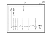
本実施形態1.に係る超音波切断装置としては、例えば、上記負荷状態検出手段により検出された負荷状態を表示部(20)に表示させる第1表示指示手段(18)を更に備える形態(例えば、図2等参照)を挙げることができる。この第1表示指示手段は、例えば、上記負荷状態を示す負荷状態グラフ(A)、及び負荷状態グラフにおいて上記刃の軌道のうちの所定の領域を示す領域情報(a〜f)を表示部に表示させることができる(例えば、図3等参照)。これにより、超音波カッターの刃の軌道上の負荷発生位置を更に容易且つ迅速に把握することができる。
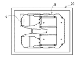
本実施形態1.に係る超音波切断装置としては、例えば、上記負荷状態検出手段により検出された負荷状態に基づいて、負荷信号が所定のしきい値を超える刃の軌道上の過負荷位置を検出する過負荷位置検出手段(17)と、刃の軌道を示す軌道図(B)、及び軌道図における過負荷位置検出手段により検出された過負荷位置(q)を表示部に表示させる第2表示指示手段(19)と、を更に備えることができる(例えば、図2及び図5等参照)。
2.車両用内装材の製造方法
本実施形態2.に係る車両用内装材の製造方法は、上記実施形態1.の超音波切断装置を用いる車両用内装材の製造方法であって、上記負荷状態検出手段により検出された負荷状態を監視しながら被切断部を超音波切断して車両用内装材を得ることを特徴とする。
2. Manufacturing method of interior material for vehicle This embodiment 2. The vehicle interior material manufacturing method according to the first embodiment is described above. A method for manufacturing a vehicle interior material using the ultrasonic cutting apparatus of
上記監視形態としては、例えば、〔1〕上記第1表示指示手段により表示部に表示される負荷状態を監視する形態(例えば、図3等参照)、〔2〕上記第2表示指示手段により表示部に表示される軌道図及び過負荷位置を監視する形態(例えば、図5等参照)等のうちの1種又は2種以上の組み合わせを挙げることができる。 As the monitoring mode, for example, [1] a mode of monitoring the load state displayed on the display unit by the first display instruction unit (see, for example, FIG. 3), [2] display by the second display instruction unit One type or a combination of two or more types of the track diagram displayed on the part and the form of monitoring the overload position (for example, see FIG. 5 and the like) can be given.
以下、図面を用いて実施例により本発明を具体的に説明する。なお、本実施例では、フロアカーペット(本発明に係る「車両用内装材」として例示する。)の複数の被切断部(例えば、輪郭部、孔部等)を超音波切断する超音波切断装置を例示する。 Hereinafter, the present invention will be specifically described with reference to the drawings. In the present embodiment, an ultrasonic cutting apparatus that ultrasonically cuts a plurality of cut portions (for example, contour portions, hole portions, etc.) of a floor carpet (illustrated as “vehicle interior material” according to the present invention). Is illustrated.
(1)超音波切断装置の構成
本実施例に係る超音波切断装置1は、図1に示すように、垂直多関節式の産業用ロボット2(本発明に係る「移動機構」として例示する。)と、この産業用ロボット2のアーム先端側2aに取り付けられる超音波カッター3と、この超音波カッター3を駆動するための発振器4と、これら産業用ロボット2及び発振器3を駆動制御するための制御装置5と、を備えている。
(1) Configuration of Ultrasonic Cutting Device As shown in FIG. 1, the
上記超音波カッター3は、圧電素子からなる振動子7と、この振動子7の超音波振動が伝達される針状の刃8と、をホルダー9に備えてなる。この振動子7は、発振器4により所定の発振周波数の電圧が印加されたときに超音波振動を発生する。また、刃8は、振動子7の振動を増幅させるホーン部(図示省略)の先端側に接続されている。
The
上記発振器4は、図2に示すように、図示しないCPU(Central Processing Unit)、RAM(Random Access Memory)、ROM(Read Only Memory)等を備えたコンピュータからなる制御部10を備えている。この制御部10は、負荷信号検知手段11に対応するプログラムをROMに記憶しながら、対応する処理をCPUに実行させる。この負荷信号検知手段11は、振動子7から出力される負荷電流(本発明に係る「振動子の負荷信号」として例示する。)を検知するとともに、その負荷電流を制御装置5に出力する。
As shown in FIG. 2, the
上記制御装置5は、図2に示すように、図示しないCPU(Central Processing Unit)、RAM(Random Access Memory)、ROM(Read Only Memory)等を備えたコンピュータからなる制御部13を備えている。この制御部13は、駆動制御手段14、発振器制御手段15、負荷状態検出手段16、過負荷位置検出手段17、第1表示指示手段18、及び第2表示指示手段19のそれぞれに対応するプログラムをROMに記憶しながら、各手段14〜19に対応する処理をCPUに実行させる。また、制御装置5は、表示モニター20(本発明に係る「表示部」として例示する。)及びキーボード等からなる入力操作部21を備えている。
As shown in FIG. 2, the
上記駆動制御手段14は、上記超音波カッター3の刃8がフロアカーペット23(図2参照)の各被切断部に対応して予め決められた所定の軌道上を通るように産業用ロボット2を駆動制御する。また、上記発振器制御手段15は、上記駆動制御手段14による駆動制御に関する情報(例えば、刃の位置、角度、速度情報等)に基づいて、振動子7に対する発振器4の励振を起動及び停止させる。具体的には、超音波カッター3の刃8がフロアカーペット23の各被切断部に近接したときに発振器4の励振が起動され、超音波カッター3の刃8がフロアカーペット23の各被切断部から離間したときに発振器4の励振が停止される。
The drive control means 14 moves the industrial robot 2 so that the
上記負荷状態検出手段16は、上記駆動制御手段14による駆動制御に関する情報に基づいて、発振器4の負荷信号検知手段11から出力される負荷電流の時間軸(即ち、時間経過)に対する強度変化を検出する。また、上記第1表示指示手段18は、入力操作部21の入力操作に基づいて、負荷状態検出手段16により検出された負荷状態を示す負荷状態グラフAを表示モニター20に表示させる(図3参照)。この負荷状態グラフAは、横軸を時間軸とし縦軸に負荷電流の強度をとり構成されている。また、第1表示指示手段18は、負荷状態グラフAにおいて発振器4の励振を起動したタイミング、すなわち各被切断部の切断開始のタイミングa〜fを表示モニター20に表示させる。これらのタイミングa〜fの隣接する間隔は、刃8の軌道上の所定の領域を示す領域情報となる。
The load
上記過負荷位置検出手段17は、上記負荷状態検出手段16により検出された負荷状態に基づいて、負荷信号が所定のしきい値p(図3参照)を超える刃8の軌道上の過負荷位置を検出する。また、上記第2表示指示手段19は、入力操作部21の入力操作に基づいて、刃8の軌道を示す軌道図B及び軌道図Bにおける過負荷位置qを表示モニターに表示させる(図5参照)。この過負荷位置qの表示は、軌道の一部を点滅させることでなされる。
The overload position detecting means 17 is based on the load state detected by the load state detecting means 16 and the overload position on the track of the
(2)超音波切断装置の作用
次に、上記構成の超音波切断装置1の作用について説明する。先ず、所定のフロアカーペット23の量産(超音波切断加工)を開始する前工程として、表示モニター20に負荷状態グラフA及び/又は軌道図Bを表示して監視しながらフロアカーペット23の各被切断部を切断する。そして、負荷状態グラフAを表示する場合において、図3に示すように、負荷状態グラフAに負荷信号の強度が強い箇所(例えば、タイミングc,dの間、タイミングe,fの間等)が生じている場合には、その箇所に対応して産業用ロボット2の駆動制御に関する情報を調整したり、フロアカーペット23を支持する治具24(図2参照)と刃8との干渉状態を調整したりする調整作業が行われる。一方、上記軌道図Bを表示する場合において、図5に示すように、その軌道図Bに過負荷位置qが表示されている場合には、その箇所に対応して上述の調整作業が行われる。その後、フロアカーペット23の量産を開始すると、負荷状態グラフAでは負荷信号の強度変化がなだらかとなり(図4参照)、軌道図Bでは過負荷位置は表示されない。
(2) Operation of Ultrasonic Cutting Device Next, the operation of the
(3)実施例の効果
以上より、本実施例の超音波切断装置1によると、駆動制御手段14により刃8が所定の軌道上を通るように産業用ロボット2が駆動制御され、負荷信号検知手段11により振動子7の負荷電流が検知され、負荷状態検出手段16により負荷電流の時間軸に対する強度変化が負荷状態として検出される。よって、この負荷状態を利用することにより、超音波カッター3の刃8の軌道上の負荷発生位置を把握することができる。その結果、超音波切断加工の不具合状況(例えば、刃折れ、刃の劣化、切断過負荷等)を詳細に把握して不良率を低減させることができる。
(3) Effects of the Embodiment From the above, according to the
また、本実施例では、第1表示指示手段18を更に備えて構成したので、第1表示指示手段18により負荷状態グラフAが表示モニター20に表示される。よって、超音波カッター3の刃8の軌道上の負荷発生位置を容易且つ迅速に把握することができる。特に、従来の負荷報知機能では把握し難かった弱負荷及びその発生位置(例えば、図3中のタイミングc,dの間等)を把握することができる。
In this embodiment, since the first display instruction means 18 is further provided, the load state graph A is displayed on the display monitor 20 by the first display instruction means 18. Therefore, the load generation position on the track of the
また、本実施例では、第1表示指示手段18により、負荷状態グラフAにおいて刃8の軌道の所定の領域を示す領域情報a〜fを表示モニター20に表示させるようにしたので、超音波カッター3の刃8の軌道上の負荷発生位置を容易且つ迅速に把握することができる。
In the present embodiment, the first display instruction means 18 causes the display monitor 20 to display the region information a to f indicating the predetermined region of the trajectory of the
さらに、本実施例では、過負荷位置検出手段17と、第2表示指示手段19と、を更に備えて構成したので、過負荷位置検出手段17により刃8の軌道上の過負荷位置が検出され、第2表示指示手段19により刃8の軌道図B及び過負荷位置qが表示モニター20に表示される。よって、超音波カッター3の刃8の軌道上の負荷発生位置を更に容易且つ迅速に把握することができる。
Further, in the present embodiment, since the overload position detection means 17 and the second display instruction means 19 are further provided, the overload position on the track of the
尚、本発明においては、上記実施例に限られず、目的、用途に応じて本発明の範囲内で種々変更した実施例とすることができる。すなわち、上記実施例では、第1及び第2表示指示手段18、19を備える形態を例示したが、これに限定されず、例えば、第1表示指示手段のみを備えるようにしてもよい。また、参考例として、第1及び第2表示指示手段18、19を備えずに、負荷状態検出手段16による負荷状態に基づいて駆動制御手段14による産業用ロボット2の駆動制御を自動調整するようにしてもよい。
In the present invention, the present invention is not limited to the above embodiment, and various modifications can be made within the scope of the present invention depending on the purpose and application. That is, in the said Example, although the form provided with the 1st and 2nd display instruction | indication means 18 and 19 was illustrated, it is not limited to this, For example, you may make it provide only a 1st display instruction means. Further, as a reference example, the first and second
また、上記実施例では、単一の表示モニター20に負荷状態グラフA及び軌道図Bを選択的に切替え表示するようにしたが、これに限定されず、例えば、単一又は複数の表示モニター20に負荷状態グラフA及び軌道図Bを同時に表示するようにしてもよい。
In the above embodiment, the load state graph A and the trajectory diagram B are selectively switched and displayed on the
また、上記実施例では、2次元表示の軌道図Bを例示したが、これに限定されず、例えば、3次元表示の軌道図としてもよい。また、上記実施例では、軌道図B上で過負荷位置qを点滅表示するようにしたが、これに限定されず、例えば、軌道図Bと異なる色、太さ等で過負荷位置qを表示するようにしてもよい。 Moreover, in the said Example, although the two-dimensional display orbit map B was illustrated, it is not limited to this, For example, it is good also as a three-dimensional display orbit map. In the above embodiment, the overload position q is displayed blinking on the track diagram B. However, the present invention is not limited to this. For example, the overload position q is displayed in a color, thickness, etc. different from the track diagram B. You may make it do.
また、上記実施例では、発振器4に設けた負荷信号検知手段11により振動子7の負荷信号を検知するようにしたが、これに限定されず、例えば、制御装置5に設けた負荷信号検知手段により振動子7の負荷信号を検知するようにしてもよい。また、上記実施例では、負荷信号として振動子7から出力される負荷電流を例示したが、これに限定されず、例えば、振動子7に印加する電圧の大きさをコントロールする回路を備え、この回路の出力電圧を負荷信号として採用してもよい。
In the above embodiment, the load
また、上記実施例では、フロアカーペット23の切断完了後に調整作業を行うようにしたが、これに限定されず、例えば、フロアカーペット23の切断途中で調整作業を行うようにしてもよい。
In the above embodiment, the adjustment work is performed after the completion of the cutting of the
また、上記実施例では、圧電素子からなる振動子7を例示したが、これに限定されず、例えば、磁歪素子からなる振動子を採用してもよい。また、上記実施例では、移動機構として垂直多関節式の産業用ロボット2を例示したが、これに限定されず、例えば、水平多関節式、直交式、パラレルリンク式の産業用ロボットを採用してもよい。また、1軸のスライド機構を採用してもよい。
Further, in the above-described embodiment, the
また、上記実施例では、表示部として、負荷状態グラフA又は軌道図Bを表示する表示モニター20を例示したが、これに限定されず、例えば、負荷状態グラフA又は軌道図Bを出力するプリンターを採用したり、負荷状態又は過負荷位置を音声出力するスピーカーを採用したりしてもよい。また、表示モニター20としてタッチパネルを採用してもよい。さらに、上記実施例における各手段11、14〜19の制御処理は、ハードウェア、ソフトウェアのいずれか又は両者により実現される。
Moreover, in the said Example, although the display monitor 20 which displays the load condition graph A or the track | orbit figure B was illustrated as a display part, it is not limited to this, For example, the printer which outputs the load condition graph A or the orbit map B Or a speaker that outputs a sound of a load state or an overload position may be employed. Further, a touch panel may be adopted as the
前述の例は単に説明を目的とするものでしかなく、本発明を限定するものと解釈されるものではない。本発明を典型的な実施形態の例を挙げて説明したが、本発明の記述および図示において使用された文言は、限定的な文言ではなく説明的および例示的なものであると理解される。ここで詳述したように、その形態において本発明の範囲または精神から逸脱することなく、添付の特許請求の範囲内で変更が可能である。ここでは、本発明の詳述に特定の構造、材料および実施例を参照したが、本発明をここにおける開示事項に限定することを意図するものではなく、むしろ、本発明は添付の特許請求の範囲内における、機能的に同等の構造、方法、使用の全てに及ぶものとする。 The foregoing examples are for illustrative purposes only and are not to be construed as limiting the invention. Although the invention has been described with reference to exemplary embodiments, it is to be understood that the language used in the description and illustration of the invention is illustrative and exemplary rather than limiting. As detailed herein, changes may be made in its form within the scope of the appended claims without departing from the scope or spirit of the invention. Although specific structures, materials and examples have been referred to in the detailed description of the invention herein, it is not intended to limit the invention to the disclosure herein, but rather, the invention is claimed. It covers all functionally equivalent structures, methods and uses within the scope.
本発明は上記で詳述した実施形態に限定されず、本発明の請求項に示した範囲で様々な変形または変更が可能である。 The present invention is not limited to the embodiments described in detail above, and various modifications or changes can be made within the scope of the claims of the present invention.
超音波切断加工に関する技術として広く利用される。特に、フロアカーペット、天井材、ドアトリム、フロアマット等の車両用内装材を超音波切断する技術として好適に利用される。 Widely used as technology related to ultrasonic cutting. In particular, it is suitably used as a technique for ultrasonically cutting vehicle interior materials such as floor carpets, ceiling materials, door trims and floor mats.
1;超音波切断装置、2;産業用ロボット、3;超音波カッター、7;振動子、8;刃、11;負荷信号検知手段、14;駆動制御手段、16;負荷状態検知手段、17;過負荷位置検出手段、18;第1表示指示手段、19;第2表示指示手段、20;表示モニター、23;フロアカーペット、A;負荷状態グラフ、B;軌道図、p;所定のしきい値、q;過負荷位置。
DESCRIPTION OF
Claims (4)
前記刃が所定の軌道上を通るように前記移動機構を駆動制御する駆動制御手段と、
前記振動子の負荷信号を検知する負荷信号検知手段と、
前記負荷信号検知手段により検知された前記負荷信号の時間軸に対する強度変化を負荷状態として検出する負荷状態検出手段と、
前記負荷状態検出手段により検出された前記負荷状態を表示部に表示させる第1表示指示手段と、を備え、
前記第1表示指示手段は、前記負荷状態を示す負荷状態グラフ上に前記刃の軌道のうちの所定の領域を示す領域情報を表示させることを特徴とする超音波切断装置。 An ultrasonic cutter having a vibrator and a blade to which ultrasonic vibration of the vibrator is transmitted, attached to a moving mechanism, and movable;
Drive control means for driving and controlling the moving mechanism so that the blade passes on a predetermined trajectory;
Load signal detecting means for detecting a load signal of the vibrator;
Load state detection means for detecting, as a load state, an intensity change with respect to the time axis of the load signal detected by the load signal detection means;
First display instruction means for displaying on the display unit the load state detected by the load state detection means,
The ultrasonic cutting apparatus according to claim 1, wherein the first display instruction unit displays region information indicating a predetermined region of the trajectory of the blade on a load state graph indicating the load state .
前記第1表示指示手段は、前記負荷状態グラフ上に前記発振器の励振を起動した複数のタイミングを表示させ、該複数のタイミングのうちの隣接するタイミングの間隔が前記領域情報となる請求項1記載の超音波切断装置。 An oscillator for applying a voltage having a predetermined oscillation frequency to the vibrator;
2. The first display instruction unit displays a plurality of timings at which excitation of the oscillator is activated on the load state graph, and an interval between adjacent timings among the plurality of timings becomes the region information. Ultrasonic cutting device.
前記刃の軌道を示す軌道図、及び該軌道図における前記過負荷位置検出手段により検出された前記過負荷位置を表示部に表示させる第2表示指示手段と、を更に備える請求項1又は2に記載の超音波切断装置。 Overload position detecting means for detecting an overload position on the blade track where the load signal exceeds a predetermined threshold based on the load state detected by the load state detecting means;
The trajectory diagram showing the trajectory of the blade, and a second display instruction means for displaying on the display section the overload position detected by the overload position detection means in the trajectory map. The ultrasonic cutting apparatus as described.
前記負荷状態検出手段により検出された前記負荷状態を監視しながら被切断部を超音波切断して車両用内装材を得ることを特徴とする車両用内装材の製造方法。 It is a manufacturing method of the interior material for vehicles using the ultrasonic cutting device according to any one of claims 1 to 3,
A method for manufacturing a vehicular interior material, wherein the cut portion is ultrasonically cut while monitoring the load state detected by the load state detection means.
Priority Applications (1)
| Application Number | Priority Date | Filing Date | Title |
|---|---|---|---|
| JP2011054707A JP5747576B2 (en) | 2011-03-11 | 2011-03-11 | Ultrasonic cutting device and method for manufacturing vehicle interior material using the same |
Applications Claiming Priority (1)
| Application Number | Priority Date | Filing Date | Title |
|---|---|---|---|
| JP2011054707A JP5747576B2 (en) | 2011-03-11 | 2011-03-11 | Ultrasonic cutting device and method for manufacturing vehicle interior material using the same |
Publications (2)
| Publication Number | Publication Date |
|---|---|
| JP2012187687A JP2012187687A (en) | 2012-10-04 |
| JP5747576B2 true JP5747576B2 (en) | 2015-07-15 |
Family
ID=47081418
Family Applications (1)
| Application Number | Title | Priority Date | Filing Date |
|---|---|---|---|
| JP2011054707A Active JP5747576B2 (en) | 2011-03-11 | 2011-03-11 | Ultrasonic cutting device and method for manufacturing vehicle interior material using the same |
Country Status (1)
| Country | Link |
|---|---|
| JP (1) | JP5747576B2 (en) |
Families Citing this family (4)
| Publication number | Priority date | Publication date | Assignee | Title |
|---|---|---|---|---|
| DE102016214699A1 (en) * | 2016-08-08 | 2018-02-08 | Sauer Gmbh | Method and device for machining a workpiece on a numerically controlled machine tool |
| JP7332150B2 (en) | 2018-10-03 | 2023-08-23 | 国立大学法人三重大学 | Synthetic resin cutting method and cutting device |
| CN111070255A (en) * | 2019-11-08 | 2020-04-28 | 桐城市千家惠塑料包装有限公司 | Cutting device for degrading plastic environment-friendly bag |
| WO2024043639A1 (en) * | 2022-08-23 | 2024-02-29 | 주식회사 엘지에너지솔루션 | Knife and secondary battery manufacturing device including same |
Family Cites Families (6)
| Publication number | Priority date | Publication date | Assignee | Title |
|---|---|---|---|---|
| JPS6234678Y2 (en) * | 1981-04-24 | 1987-09-03 | ||
| JPS61241048A (en) * | 1985-04-16 | 1986-10-27 | Shimada Phys & Chem Ind Co Ltd | Supervisory method for ultrasonic machining |
| JPH01140947A (en) * | 1987-11-25 | 1989-06-02 | Mitsubishi Electric Corp | Numerical control device |
| JPH04123107A (en) * | 1990-09-13 | 1992-04-23 | Fanuc Ltd | Load state plotting system |
| DE19630096C2 (en) * | 1996-07-25 | 1998-07-09 | Georg Geis Maschinenfabrik | Device for the spatial cutting of thin-walled molded parts |
| JP3073195B1 (en) * | 1999-01-29 | 2000-08-07 | 住友特殊金属株式会社 | Work cutting device and work cutting method |
-
2011
- 2011-03-11 JP JP2011054707A patent/JP5747576B2/en active Active
Also Published As
| Publication number | Publication date |
|---|---|
| JP2012187687A (en) | 2012-10-04 |
Similar Documents
| Publication | Publication Date | Title |
|---|---|---|
| JP5747576B2 (en) | Ultrasonic cutting device and method for manufacturing vehicle interior material using the same | |
| CN105813589B (en) | The working method of ultrasonic treating system, energy unit and energy unit | |
| KR100759919B1 (en) | Robot cleaner and control method thereof | |
| JP4646905B2 (en) | Cutting machine and method of moving cutting head | |
| JP6562275B2 (en) | Method and apparatus for cutting work material by application of ultrasonic energy | |
| JP5442629B2 (en) | Vibration cutting apparatus and vibration cutting method | |
| CN105144008A (en) | Numerical control device | |
| WO2006001479A1 (en) | Error detection method and motor control device | |
| JP2015213937A (en) | Tip dressing system with dressing device for cutting electrode tip of spot welding gun | |
| JP2006130976A5 (en) | ||
| JP2006036148A (en) | Airbag cover manufacturing device | |
| JP2009172668A (en) | Laser scribing apparatus and laser scribing method | |
| JP2006102889A (en) | Abnormality-determining device of speed reducer and abnormality-determining method of speed reducer | |
| JP6456434B2 (en) | Vibration source estimation device | |
| KR102031895B1 (en) | Friction Stir Point Bonding Device and Friction Stir Point Bonding Method | |
| CN102198606A (en) | Diagnostic device for knife point of cutting element of machine tool | |
| JP2009202335A (en) | Abnormality determination device and abnormality determination method for reduction gear | |
| CN109883661A (en) | Cutting knife-breaking detecting method based on vibration analysis | |
| WO2018179499A1 (en) | Cutting device | |
| JP6386484B2 (en) | Electrical device with foreign object detection panel | |
| EP3690277B1 (en) | Couplings that actively stabilize vibrations | |
| KR20180099396A (en) | Ultrasonic cutting device | |
| JP2011041993A (en) | Ultrasonic cutting horn | |
| JPS62266094A (en) | Sewing machine | |
| JP2014018822A (en) | Tool exchange method, and device |
Legal Events
| Date | Code | Title | Description |
|---|---|---|---|
| A621 | Written request for application examination |
Free format text: JAPANESE INTERMEDIATE CODE: A621 Effective date: 20131016 |
|
| RD04 | Notification of resignation of power of attorney |
Free format text: JAPANESE INTERMEDIATE CODE: A7424 Effective date: 20140617 |
|
| A977 | Report on retrieval |
Free format text: JAPANESE INTERMEDIATE CODE: A971007 Effective date: 20140925 |
|
| A131 | Notification of reasons for refusal |
Free format text: JAPANESE INTERMEDIATE CODE: A131 Effective date: 20140930 |
|
| A521 | Request for written amendment filed |
Free format text: JAPANESE INTERMEDIATE CODE: A523 Effective date: 20141119 |
|
| TRDD | Decision of grant or rejection written | ||
| A01 | Written decision to grant a patent or to grant a registration (utility model) |
Free format text: JAPANESE INTERMEDIATE CODE: A01 Effective date: 20150414 |
|
| A61 | First payment of annual fees (during grant procedure) |
Free format text: JAPANESE INTERMEDIATE CODE: A61 Effective date: 20150427 |
|
| R151 | Written notification of patent or utility model registration |
Ref document number: 5747576 Country of ref document: JP Free format text: JAPANESE INTERMEDIATE CODE: R151 |
|
| R250 | Receipt of annual fees |
Free format text: JAPANESE INTERMEDIATE CODE: R250 |
|
| R250 | Receipt of annual fees |
Free format text: JAPANESE INTERMEDIATE CODE: R250 |
|
| R250 | Receipt of annual fees |
Free format text: JAPANESE INTERMEDIATE CODE: R250 |
|
| R250 | Receipt of annual fees |
Free format text: JAPANESE INTERMEDIATE CODE: R250 |
|
| R250 | Receipt of annual fees |
Free format text: JAPANESE INTERMEDIATE CODE: R250 |
|
| R250 | Receipt of annual fees |
Free format text: JAPANESE INTERMEDIATE CODE: R250 |