JP6619399B2 - Method, apparatus, machine tool, and computer program product for machining a workpiece with a numerically controlled machine tool - Google Patents
Method, apparatus, machine tool, and computer program product for machining a workpiece with a numerically controlled machine tool Download PDFInfo
- Publication number
- JP6619399B2 JP6619399B2 JP2017149869A JP2017149869A JP6619399B2 JP 6619399 B2 JP6619399 B2 JP 6619399B2 JP 2017149869 A JP2017149869 A JP 2017149869A JP 2017149869 A JP2017149869 A JP 2017149869A JP 6619399 B2 JP6619399 B2 JP 6619399B2
- Authority
- JP
- Japan
- Prior art keywords
- workpiece
- tool
- sensor signal
- ultrasonic generator
- machine tool
- Prior art date
- Legal status (The legal status is an assumption and is not a legal conclusion. Google has not performed a legal analysis and makes no representation as to the accuracy of the status listed.)
- Active
Links
- 238000003754 machining Methods 0.000 title claims description 45
- 238000000034 method Methods 0.000 title claims description 45
- 238000004590 computer program Methods 0.000 title claims description 12
- 239000000463 material Substances 0.000 claims description 118
- 230000008859 change Effects 0.000 claims description 51
- 238000012545 processing Methods 0.000 claims description 38
- 230000033001 locomotion Effects 0.000 claims description 15
- 238000011156 evaluation Methods 0.000 claims description 10
- 238000001514 detection method Methods 0.000 claims description 7
- 230000008569 process Effects 0.000 claims description 6
- 239000002131 composite material Substances 0.000 claims description 4
- 239000011521 glass Substances 0.000 claims description 4
- 229920000049 Carbon (fiber) Polymers 0.000 claims description 2
- 239000004917 carbon fiber Substances 0.000 claims description 2
- 229910010293 ceramic material Inorganic materials 0.000 claims description 2
- 238000013500 data storage Methods 0.000 claims description 2
- VNWKTOKETHGBQD-UHFFFAOYSA-N methane Chemical compound C VNWKTOKETHGBQD-UHFFFAOYSA-N 0.000 claims description 2
- 239000011208 reinforced composite material Substances 0.000 claims description 2
- 238000002604 ultrasonography Methods 0.000 claims description 2
- 230000036962 time dependent Effects 0.000 claims 1
- 230000007704 transition Effects 0.000 claims 1
- 238000004804 winding Methods 0.000 description 18
- 230000008901 benefit Effects 0.000 description 10
- 230000005540 biological transmission Effects 0.000 description 7
- 238000005259 measurement Methods 0.000 description 7
- 238000012546 transfer Methods 0.000 description 7
- XEEYBQQBJWHFJM-UHFFFAOYSA-N Iron Chemical group [Fe] XEEYBQQBJWHFJM-UHFFFAOYSA-N 0.000 description 6
- 238000013016 damping Methods 0.000 description 6
- 238000001228 spectrum Methods 0.000 description 5
- 238000011161 development Methods 0.000 description 4
- 238000010586 diagram Methods 0.000 description 4
- 239000000919 ceramic Substances 0.000 description 3
- 230000001965 increasing effect Effects 0.000 description 3
- 238000012986 modification Methods 0.000 description 3
- 230000004048 modification Effects 0.000 description 3
- 238000013459 approach Methods 0.000 description 2
- 238000010438 heat treatment Methods 0.000 description 2
- 238000012360 testing method Methods 0.000 description 2
- RTAQQCXQSZGOHL-UHFFFAOYSA-N Titanium Chemical compound [Ti] RTAQQCXQSZGOHL-UHFFFAOYSA-N 0.000 description 1
- XAGFODPZIPBFFR-UHFFFAOYSA-N aluminium Chemical compound [Al] XAGFODPZIPBFFR-UHFFFAOYSA-N 0.000 description 1
- 229910052782 aluminium Inorganic materials 0.000 description 1
- 230000002238 attenuated effect Effects 0.000 description 1
- 239000004918 carbon fiber reinforced polymer Substances 0.000 description 1
- 230000009351 contact transmission Effects 0.000 description 1
- 239000013078 crystal Substances 0.000 description 1
- 230000007547 defect Effects 0.000 description 1
- 230000001419 dependent effect Effects 0.000 description 1
- 239000013070 direct material Substances 0.000 description 1
- 230000000694 effects Effects 0.000 description 1
- 230000005284 excitation Effects 0.000 description 1
- 230000001939 inductive effect Effects 0.000 description 1
- 230000001788 irregular Effects 0.000 description 1
- 239000000203 mixture Substances 0.000 description 1
- 238000012544 monitoring process Methods 0.000 description 1
- 230000003287 optical effect Effects 0.000 description 1
- 230000008092 positive effect Effects 0.000 description 1
- 230000004044 response Effects 0.000 description 1
- 230000008054 signal transmission Effects 0.000 description 1
- 239000000126 substance Substances 0.000 description 1
- 239000010936 titanium Substances 0.000 description 1
- 229910052719 titanium Inorganic materials 0.000 description 1
Images


Classifications
-
- G—PHYSICS
- G05—CONTROLLING; REGULATING
- G05B—CONTROL OR REGULATING SYSTEMS IN GENERAL; FUNCTIONAL ELEMENTS OF SUCH SYSTEMS; MONITORING OR TESTING ARRANGEMENTS FOR SUCH SYSTEMS OR ELEMENTS
- G05B19/00—Programme-control systems
- G05B19/02—Programme-control systems electric
- G05B19/18—Numerical control [NC], i.e. automatically operating machines, in particular machine tools, e.g. in a manufacturing environment, so as to execute positioning, movement or co-ordinated operations by means of programme data in numerical form
- G05B19/416—Numerical control [NC], i.e. automatically operating machines, in particular machine tools, e.g. in a manufacturing environment, so as to execute positioning, movement or co-ordinated operations by means of programme data in numerical form characterised by control of velocity, acceleration or deceleration
-
- B—PERFORMING OPERATIONS; TRANSPORTING
- B23—MACHINE TOOLS; METAL-WORKING NOT OTHERWISE PROVIDED FOR
- B23Q—DETAILS, COMPONENTS, OR ACCESSORIES FOR MACHINE TOOLS, e.g. ARRANGEMENTS FOR COPYING OR CONTROLLING; MACHINE TOOLS IN GENERAL CHARACTERISED BY THE CONSTRUCTION OF PARTICULAR DETAILS OR COMPONENTS; COMBINATIONS OR ASSOCIATIONS OF METAL-WORKING MACHINES, NOT DIRECTED TO A PARTICULAR RESULT
- B23Q17/00—Arrangements for observing, indicating or measuring on machine tools
- B23Q17/20—Arrangements for observing, indicating or measuring on machine tools for indicating or measuring workpiece characteristics, e.g. contour, dimension, hardness
-
- B—PERFORMING OPERATIONS; TRANSPORTING
- B23—MACHINE TOOLS; METAL-WORKING NOT OTHERWISE PROVIDED FOR
- B23B—TURNING; BORING
- B23B49/00—Measuring or gauging equipment on boring machines for positioning or guiding the drill; Devices for indicating failure of drills during boring; Centering devices for holes to be bored
-
- B—PERFORMING OPERATIONS; TRANSPORTING
- B23—MACHINE TOOLS; METAL-WORKING NOT OTHERWISE PROVIDED FOR
- B23B—TURNING; BORING
- B23B37/00—Boring by making use of ultrasonic energy
-
- B—PERFORMING OPERATIONS; TRANSPORTING
- B23—MACHINE TOOLS; METAL-WORKING NOT OTHERWISE PROVIDED FOR
- B23Q—DETAILS, COMPONENTS, OR ACCESSORIES FOR MACHINE TOOLS, e.g. ARRANGEMENTS FOR COPYING OR CONTROLLING; MACHINE TOOLS IN GENERAL CHARACTERISED BY THE CONSTRUCTION OF PARTICULAR DETAILS OR COMPONENTS; COMBINATIONS OR ASSOCIATIONS OF METAL-WORKING MACHINES, NOT DIRECTED TO A PARTICULAR RESULT
- B23Q15/00—Automatic control or regulation of feed movement, cutting velocity or position of tool or work
- B23Q15/007—Automatic control or regulation of feed movement, cutting velocity or position of tool or work while the tool acts upon the workpiece
- B23Q15/013—Control or regulation of feed movement
-
- B—PERFORMING OPERATIONS; TRANSPORTING
- B23—MACHINE TOOLS; METAL-WORKING NOT OTHERWISE PROVIDED FOR
- B23Q—DETAILS, COMPONENTS, OR ACCESSORIES FOR MACHINE TOOLS, e.g. ARRANGEMENTS FOR COPYING OR CONTROLLING; MACHINE TOOLS IN GENERAL CHARACTERISED BY THE CONSTRUCTION OF PARTICULAR DETAILS OR COMPONENTS; COMBINATIONS OR ASSOCIATIONS OF METAL-WORKING MACHINES, NOT DIRECTED TO A PARTICULAR RESULT
- B23Q15/00—Automatic control or regulation of feed movement, cutting velocity or position of tool or work
- B23Q15/007—Automatic control or regulation of feed movement, cutting velocity or position of tool or work while the tool acts upon the workpiece
- B23Q15/12—Adaptive control, i.e. adjusting itself to have a performance which is optimum according to a preassigned criterion
-
- B—PERFORMING OPERATIONS; TRANSPORTING
- B23—MACHINE TOOLS; METAL-WORKING NOT OTHERWISE PROVIDED FOR
- B23Q—DETAILS, COMPONENTS, OR ACCESSORIES FOR MACHINE TOOLS, e.g. ARRANGEMENTS FOR COPYING OR CONTROLLING; MACHINE TOOLS IN GENERAL CHARACTERISED BY THE CONSTRUCTION OF PARTICULAR DETAILS OR COMPONENTS; COMBINATIONS OR ASSOCIATIONS OF METAL-WORKING MACHINES, NOT DIRECTED TO A PARTICULAR RESULT
- B23Q15/00—Automatic control or regulation of feed movement, cutting velocity or position of tool or work
- B23Q15/007—Automatic control or regulation of feed movement, cutting velocity or position of tool or work while the tool acts upon the workpiece
- B23Q15/18—Compensation of tool-deflection due to temperature or force
-
- B—PERFORMING OPERATIONS; TRANSPORTING
- B23—MACHINE TOOLS; METAL-WORKING NOT OTHERWISE PROVIDED FOR
- B23Q—DETAILS, COMPONENTS, OR ACCESSORIES FOR MACHINE TOOLS, e.g. ARRANGEMENTS FOR COPYING OR CONTROLLING; MACHINE TOOLS IN GENERAL CHARACTERISED BY THE CONSTRUCTION OF PARTICULAR DETAILS OR COMPONENTS; COMBINATIONS OR ASSOCIATIONS OF METAL-WORKING MACHINES, NOT DIRECTED TO A PARTICULAR RESULT
- B23Q17/00—Arrangements for observing, indicating or measuring on machine tools
- B23Q17/09—Arrangements for observing, indicating or measuring on machine tools for indicating or measuring cutting pressure or for determining cutting-tool condition, e.g. cutting ability, load on tool
- B23Q17/0952—Arrangements for observing, indicating or measuring on machine tools for indicating or measuring cutting pressure or for determining cutting-tool condition, e.g. cutting ability, load on tool during machining
-
- G—PHYSICS
- G01—MEASURING; TESTING
- G01B—MEASURING LENGTH, THICKNESS OR SIMILAR LINEAR DIMENSIONS; MEASURING ANGLES; MEASURING AREAS; MEASURING IRREGULARITIES OF SURFACES OR CONTOURS
- G01B17/00—Measuring arrangements characterised by the use of infrasonic, sonic or ultrasonic vibrations
-
- B—PERFORMING OPERATIONS; TRANSPORTING
- B23—MACHINE TOOLS; METAL-WORKING NOT OTHERWISE PROVIDED FOR
- B23B—TURNING; BORING
- B23B2260/00—Details of constructional elements
- B23B2260/128—Sensors
-
- B—PERFORMING OPERATIONS; TRANSPORTING
- B23—MACHINE TOOLS; METAL-WORKING NOT OTHERWISE PROVIDED FOR
- B23B—TURNING; BORING
- B23B2270/00—Details of turning, boring or drilling machines, processes or tools not otherwise provided for
- B23B2270/10—Use of ultrasound
-
- B—PERFORMING OPERATIONS; TRANSPORTING
- B23—MACHINE TOOLS; METAL-WORKING NOT OTHERWISE PROVIDED FOR
- B23B—TURNING; BORING
- B23B2270/00—Details of turning, boring or drilling machines, processes or tools not otherwise provided for
- B23B2270/48—Measuring or detecting
-
- G—PHYSICS
- G05—CONTROLLING; REGULATING
- G05B—CONTROL OR REGULATING SYSTEMS IN GENERAL; FUNCTIONAL ELEMENTS OF SUCH SYSTEMS; MONITORING OR TESTING ARRANGEMENTS FOR SUCH SYSTEMS OR ELEMENTS
- G05B2219/00—Program-control systems
- G05B2219/30—Nc systems
- G05B2219/45—Nc applications
- G05B2219/45206—Ultrasonic drill, mill, machining
Description
本発明は、数値制御工作機械にてワークピースを工具で加工する方法に関する。また、本発明は、上記方法が実施可能な装置及び工作機械に関する。更にまた、本発明は上述の方法を実施可能にするコンピュータプログラム製品に関する。 The present invention relates to a method of machining a workpiece with a tool in a numerically controlled machine tool. The present invention also relates to an apparatus and a machine tool capable of performing the above method. Furthermore, the invention relates to a computer program product that makes it possible to carry out the method described above.
従来技術にて、例えば、ワークピースが工具で加工されるとき、工具の回転運動に工具の超音波振動を重ね合わせ可能な工作機械がよく知られている。 In the prior art, for example, when a workpiece is machined with a tool, a machine tool that can superimpose the ultrasonic vibration of the tool on the rotational motion of the tool is well known.
この点に関し、以下の特許文献1は工具ホルダを備えた工具を記載し、該工具ホルダは第1端に回転スピンドルノーズに適合した工具ホルダサポートと、第1端とは反対側の第2端に工具サポートと、該工具サポートに挿入可能な工具ヘッドとを有し、工具ホルダは振動モータを含む。 In this regard, the following Patent Document 1 describes a tool including a tool holder, which includes a tool holder support adapted to a rotating spindle nose at a first end and a second end opposite to the first end. And a tool head insertable into the tool support, and the tool holder includes a vibration motor.
このような工作機械の場合、工具に超音波振動を発生させる工具ホルダ内の超音波発生器、振動本体及び工具ホルダに挿入された工具は振動系を提供し、該振動系は機械的に振動すべく電気信号によって励振される。ここで、振動系がその共振周波数で励振されとき、可能な最大の機械振動の振幅が得られる。 In such a machine tool, the ultrasonic generator in the tool holder that generates ultrasonic vibrations in the tool, the vibration body, and the tool inserted in the tool holder provide a vibration system, and the vibration system mechanically vibrates. It is excited by an electrical signal. Here, the maximum possible mechanical vibration amplitude is obtained when the vibration system is excited at its resonant frequency.
工具がワーク内に前進されるとき、振動系はワークピースの材料や、ワークピースと工具との間の摩擦によって減衰され、共振周波数が幾分低い共振周波数に変移される。ここで、共振周波数が減衰の増加と共に更に変移されることは公知である。 As the tool is advanced into the workpiece, the vibration system is damped by the workpiece material and the friction between the workpiece and the tool, and the resonant frequency is shifted to a somewhat lower resonant frequency. Here, it is known that the resonant frequency is further shifted with increasing attenuation.
このことは加工中、共振周波数の著しい変動をもたらす不具合を屡々伴う。しかしながら、このことは同時に、加工されている材料の減衰能力が変化したことを意味する。 This is often accompanied by defects that cause significant fluctuations in the resonance frequency during processing. However, this also means that the damping capacity of the material being processed has changed.
これは、ワークピースの材料が明らかに均質であるにも拘わらず、(結晶粒界や異物含有等の)不均一性が生じる故のワークピース内での材料変化に起因する。このような材料変化のために、所定の加工パラメータを調整する必要があり、該加工パラメータにより、工具は各々の材料及びその特性に対してワークピースを加工する。 This is due to material changes within the workpiece due to inhomogeneities (such as grain boundaries and inclusion of foreign matter) despite the apparent homogeneity of the workpiece material. Due to such material changes, it is necessary to adjust predetermined machining parameters, which allow the tool to machine a workpiece for each material and its properties.
しかしながら、ワークピース内でのボア又は凹所等の幾何学的な変化もまた、ワークピース材料の不均一性の一種であり、該不均一性は所定の加工パラメータに影響する。 However, geometric changes such as bores or recesses within the workpiece are also a type of workpiece material non-uniformity, which affects certain processing parameters.
ワークピースが加工されている間、材料変化が生じる時点を決定する測定システムが既に公知であり、該測定システムは物体伝播音(body-borne sound)の原理を利用する。機械フレームには通常、対応する物体伝播音センサがワークピースから大きく離れて取り付けられ、該センサは発生する振動を測定し、該振動から測定信号を発生する。これら測定信号は制御ユニットで評価され、該制御ユニットはその評価にて、測定信号の偏差が検出されたなら、加工中、所定の加工パラメータを変化させることができる。 Measurement systems are already known that determine when material changes occur while a workpiece is being processed, and the measurement system utilizes the principle of body-borne sound. The machine frame is usually fitted with a corresponding object propagation sound sensor at a large distance from the workpiece, which measures the generated vibration and generates a measurement signal from the vibration. These measurement signals are evaluated by the control unit, and if the deviation of the measurement signal is detected by the control unit, the predetermined processing parameters can be changed during the processing.
しかしながら、測定センサが遠く離れて置かれているために、発生した信号がワークピース内材料の変化に専ら起因したものでないという不具合がある。発生した信号は環境からの振動に影響されるか又は重畳されている。このことは、測定信号の不適切な評価を導き、この結果、加工パラメータの調整を誤る。 However, since the measurement sensor is located far away, there is a problem that the generated signal is not caused solely by the change in the material in the workpiece. The generated signal is affected or superimposed by vibrations from the environment. This leads to an improper evaluation of the measurement signal, which results in incorrect adjustment of the processing parameters.
この理由のため、ワークピースが加工されている間、可能な限り、外部の振動の重畳を回避するため、ワークピース自体に対して可能限り近くで材料の変化を検出することが重要である。 For this reason, it is important to detect material changes as close as possible to the workpiece itself in order to avoid the superposition of external vibrations as much as possible while the workpiece is being machined.
それ故、本発明の目的は、上述の不具合を回避可能にし、数値制御工作機械にてワークピースを加工する方法を提供することにある。 Therefore, an object of the present invention is to provide a method of machining a workpiece with a numerically controlled machine tool that makes it possible to avoid the above-mentioned problems.
本発明の別の目的は、本発明の方法が実施可能な装置、工作機械及びコンピュータプログラム製品を提供することにある。 Another object of the present invention is to provide an apparatus, a machine tool and a computer program product capable of implementing the method of the present invention.
上述の目的は、請求項1の方法、請求項16の装置、請求項17の工作機械及び請求項18のコンピュータプログラム製品によって達成される。従属請求項は本発明の方法の好適な実施形態に係わる。 The above object is achieved by the method of claim 1, the apparatus of claim 16, the machine tool of claim 17, and the computer program product of claim 18. The dependent claims relate to preferred embodiments of the method according to the invention.
数値制御工作機械にてワークピースを工具で加工する本発明の方法は、ワークピースを加工するためにワークピースに対する工具の相対移動を制御する工程と、超音波発生器によって工具に超音波振動を発生させる工程と、超音波発生器から出力される少なくとも1つのセンサ信号を検出する工程と、ワークピースに対する工具の相対移動が制御されながら超音波発生器から出力された少なくとも1つのセンサ信号に基づき、ワークピースでの材料の変化を同定する工程とを含む。 The method of the present invention for machining a workpiece with a tool in a numerically controlled machine tool includes the steps of controlling the relative movement of the tool with respect to the workpiece to machine the workpiece, and applying ultrasonic vibration to the tool by an ultrasonic generator. And generating at least one sensor signal output from the ultrasonic generator, and based on at least one sensor signal output from the ultrasonic generator while controlling the relative movement of the tool with respect to the workpiece. Identifying material changes in the workpiece.
超音波発生器は工具に振動を誘起するのに役立ち、また、振動系の共振周波数を検出するセンサとしても役立つ。本方法の利点は、超音波発生器が工具の直近で且つ工具及びワークピースと共に一列に配置されていることである。それ故、入手可能な材料の各自の共振周波数及び減衰能力がワークピースに非常に近接して検出可能となり、外部の振動源の影響が大幅に減少される。 The ultrasonic generator serves to induce vibrations in the tool, and also serves as a sensor for detecting the resonance frequency of the vibration system. The advantage of this method is that the ultrasonic generator is placed in close proximity to the tool and with the tool and workpiece. Therefore, the respective resonant frequency and damping capability of the available material can be detected very close to the workpiece, and the influence of external vibration sources is greatly reduced.
付け加えて、ワークピース内での材料変化が1つの材料から次の材料の変わり目で正確に認識可能となり、この情報は工具のコントローラに適切に伝送可能となる。 In addition, material changes in the workpiece can be accurately recognized from one material to the next, and this information can be properly transmitted to the tool controller.
発明の有利な進展は、ワークピースに対する工具の相対移動の制御が所定の加工パラメータに基づいて実施されることであり、ここでは、好ましくは、方法は次の工程を更に含む。超音波発生器から出力された少なくとも1つのセンサ信号に基づき、ワークピースでの材料変化が認識されたとき、所定の加工パラメータを調整する工程及び/又は調整された加工パラメータに基づき、ワークピースに対する工具の相対移動を制御する工程。 An advantageous development of the invention is that the control of the relative movement of the tool with respect to the workpiece is carried out on the basis of predetermined machining parameters, wherein preferably the method further comprises the following steps: Based on at least one sensor signal output from the ultrasonic generator, when a material change in the workpiece is recognized, adjusting a predetermined processing parameter and / or based on the adjusted processing parameter The process of controlling the relative movement of the tool.
所定の加工パラメータは、材料各自をその加工に必要なパラメータで適切に加工するために、超音波発生器のセンサ信号に依存して制御可能である。 The predetermined processing parameters can be controlled depending on the sensor signal of the ultrasonic generator in order to appropriately process each material with the parameters necessary for the processing.
付加的な利点は、外部の振動源の影響が最大限に減少可能であるために、各材料にとっての一種の「指紋」(例えば、振動系の或る減衰共振周波数及び/又は材料の或る減衰能力)が生成され且つ記憶されることにある。 An additional advantage is that a kind of “fingerprint” for each material (eg, some damped resonant frequency of the vibration system and / or some of the material) because the influence of the external vibration source can be reduced to the maximum. The damping capacity) is generated and stored.
このことは、1つのワークピースで、広範囲に異なる材料(炭素繊維強化プラスチック材料及びチタニウム/アルミニウム)が屡々互いに組み合わされるので、例えば複合材料の場合に大きな利点となる。これは、全ての材料のための加工パラメータを対応して調整する要求又は必要性をもたらす。加工の予備段階においては材料の各自の層厚が屡々、正確なクランプに基づいてプログラムされ、このため、加工中、加工パラメータが調整される。 This is a great advantage, for example in the case of composite materials, since a wide range of different materials (carbon fiber reinforced plastic material and titanium / aluminum) are often combined together in one workpiece. This results in the requirement or need to correspondingly adjust the processing parameters for all materials. In the preliminary stage of processing, the respective layer thickness of the material is often programmed on the basis of an exact clamp, so that the processing parameters are adjusted during processing.
しかしながら、ワークピースのクランプでは層厚の変動や不揃いが機械的に存在するので、材料の幾つかは不適切な加工パラメータで常時加工される。今、発明によりワークピース内の材料変化を正確に同定し、そして、材料各自の加工パラメータを調整することが可能となる。 However, because of workpiece thickness variations and irregularities in the workpiece clamp, some of the material is always machined with improper machining parameters. The invention now makes it possible to accurately identify material changes in the workpiece and to adjust the processing parameters of each material.
発明における別の好都合な進展は、ワークピースが少なくとも2つの異なる材料領域を含み、ここでは、「ワークピースにて材料の変化を同定する」工程にて、ワークピースでの1つの材料領域から他の材料領域への工具の変わり目が同定されることである。 Another advantageous development in the invention is that the workpiece includes at least two different material regions, where in the step “identify material changes in the workpiece”, one material region in the workpiece is another. The turn of the tool into the material region is identified.
ここで、上述の方法は、材料変化が制限された数に限定されず、不定数の材料変化を同定でき、このために工具の加工パラメータが調整され得る。 Here, the method described above is not limited to a limited number of material changes, but can identify an infinite number of material changes, for which the machining parameters of the tool can be adjusted.
付け加えて、方法は、ワークピースが複合材料、特に炭素繊維強化複合材料及び/又はガラス及び/又はセラミック材料を含むべく好都合に進展され得る。 In addition, the method may be advantageously advanced so that the workpiece comprises a composite material, in particular a carbon fiber reinforced composite material and / or glass and / or ceramic material.
或る材料に対しての発明の制限は存在しない。また、複合材料、ガラス及びセラミックは好都合に「指紋」(共振周波数特性及び/又は減衰能力)を残し、該「指紋」は記憶され、そして、所定の加工パラメータを調整するのに使用可能である。 There are no invention limitations on certain materials. Also, composite materials, glass and ceramics advantageously leave a “fingerprint” (resonant frequency characteristics and / or attenuation capability) that is stored and can be used to adjust certain processing parameters. .
発明は、材料領域が異なる材料又は材料特性の層をなし、又は、材料領域がワークピース内の含有材料又は材料領域がワークピース内のボア及び/又は凹所であるように好都合にて進展され得る。 The invention is advantageously developed so that the material regions form layers of different materials or material properties, or the material regions are contained materials or material regions in the workpiece are bores and / or recesses in the workpiece. obtain.
材料及び/又は材料領域の変化は、異なる材料特質によって識別可能で、また、ワークピース内での幾何学的な変化によって特徴付け可能である。 Changes in materials and / or material regions can be distinguished by different material characteristics and can be characterized by geometric changes within the workpiece.
例えば、加工中、工具がワークピースの材料からワークピースのボア内(多分、その一部のみ)で働くことも可能である。また、このことはその位置で、ワークピースの共振周波数及び/又は減衰能力の変化、つまり、材料の或る種の変化を導く。この場合にも同様に、所定の加工パラメータを調整することが望まれる。 For example, during machining, it is possible for the tool to work from the workpiece material into the workpiece bore (perhaps only a portion thereof). This also leads to changes in the resonant frequency and / or damping capacity of the workpiece, ie some change in material, at that position. In this case as well, it is desirable to adjust predetermined processing parameters.
発明は、「ワークピースにて材料の変化を同定する」工程にて、ワークピースの表面との工具の接触(即ち、ワークピース内で材料変化に対比して、例えば空気からワークピースの表面への材料変化)が同定されるように好都合に進展され得る。 The invention relates to the contact of the tool with the surface of the workpiece (ie, from the air to the surface of the workpiece, for example, in contrast to the material change in the workpiece in the step of “identifying material changes at the workpiece”). Material changes) can be expediently developed.
特に大きな利点は、ワークピースに対する非常に迅速なアプローチが確保され、これにより、加工時間の短縮が可能となる。このことは特に、材料がガラス又はセラミック等の壊れ易い場合に利点となる。 A particularly great advantage is that a very quick approach to the workpiece is ensured, which makes it possible to reduce the machining time. This is particularly advantageous when the material is fragile, such as glass or ceramic.
このような材料からなるワークピースに対し、工具はワークピースに出会うためだけに所定の安全距離まで高速でアプローチし、この後、加工が所定の加工パラメータで継続され、ここでの加工パラメータは比較的遅い。選択された安全距離が余りにも長ければ、加工時間が不必要に浪費される。 For a workpiece made of such a material, the tool approaches at high speed to a predetermined safe distance only to meet the workpiece, after which the processing continues with the predetermined processing parameters, where the processing parameters are compared. Slow. If the selected safety distance is too long, machining time is unnecessarily wasted.
材料変化(例えば、空気からワークピースの表面)の同定に起因し、対応した材料への所定の加工パラメータの調整が実施される前に、工具は空気からワークピースの実際の境界まで高速で移動可能である。 Due to the identification of material changes (e.g. air to the surface of the workpiece), the tool moves at high speed from the air to the actual boundary of the workpiece before the adjustment of the predetermined processing parameters to the corresponding material is performed Is possible.
付け加えて、方法は、「ワークピースにて材料の変化を同定する」工程にて、超音波発生器におけるセンサ信号の1つ以上の経時的な変化及び同時に値の変化が相応して検出されるように好都合に進展され得る。 In addition, the method detects, in the “identify material changes at the workpiece” step, one or more changes in sensor signal in the ultrasonic generator over time and changes in value accordingly. Can be expediently developed.
ここでの進展の利点は、振動系における共振周波数の変化が材料の変化以外の理由を有することである。加工操作は時には多量の熱を発生し、該熱は或る程度、工具又はワークピースを強く加熱する。 The advantage of the progress here is that the change in resonance frequency in the vibration system has reasons other than the change in material. Machining operations sometimes generate a large amount of heat, which to some extent strongly heats the tool or workpiece.
また、該加熱は振動系の共振周波数に相当影響する。しかしながら、これらの影響は材料の変化の理由から識別可能である。 In addition, the heating significantly affects the resonance frequency of the vibration system. However, these effects are distinguishable for reasons of material change.
振動系の共振周波数は、工具及び/又はワークピースの加熱のために比較的長い期間に亘って連続的に変化する。このことは、共振周波数の急激な変化を示す材料変化の発生とは矛盾する。 The resonant frequency of the oscillating system changes continuously over a relatively long period due to the heating of the tool and / or workpiece. This contradicts the occurrence of a material change that shows a sudden change in resonance frequency.
ここで、センサ信号の1つ以上の経時的な変化及びセンサ信号の相応のパラメータの値の変化の両方を検出するのが好ましい。各センサ信号はノイズを有し、該ノイズはパラメータにおいて、特に一時的に急であるもの低い変化を示す。 Here, it is preferable to detect both one or more changes in the sensor signal over time and changes in the values of the corresponding parameters of the sensor signal. Each sensor signal has noise, which indicates a low change in the parameter, particularly a temporary sudden one.
それ故、検出されるのは経時的な変化だけでなく、好ましくは、相応のパラメータの値の変化もまた検出される。この組み合わせは、材料変化の存在に関して、好都合且つ確実な供述の根拠を形成する。 Therefore, it is not only detected changes over time , but preferably also changes in the values of the corresponding parameters are detected. This combination forms the basis for a convenient and reliable statement regarding the presence of material changes.
また、発明は次の工程によって好都合に進展され得る。超音波発生器における少なくとも1つのセンサ信号の経時的な変化及びその値の変化が所定の変化時間よりも相応して大きく下回り且つ同時に所定の変化値を超えたか決定する工程。 In addition, the invention can be advantageously advanced by the following steps. Determining whether the change over time of the at least one sensor signal in the ultrasonic generator and the change in its value are correspondingly significantly less than the predetermined change time and simultaneously exceed the predetermined change value.
センサ信号におけるパラメータの経時的な変化及びその値の変化を決定することに加えて、センサ信号における各自の変化の制限値を決定することも必要である。 In addition to determining the change in parameter and its value over time in the sensor signal, it is also necessary to determine a limit value for each change in the sensor signal.
この根拠に基づき、材料における変化の発生は、制限値を超えるか又は下回ることで決定可能となり、(ワークピース/工具の温度変化等の)他の要因から大きく識別可能となる。 Based on this basis, the occurrence of changes in the material can be determined by exceeding or below the limit value, and can be largely distinguished from other factors (such as workpiece / tool temperature changes).
更にまた、発明は、超音波発生器における少なくとも1つのセンサ信号の経時的な変化及びその値の変化が所定の変化時間を相当に下回り且つ所定の変化値を超えたとき、所定の加工パラメータが調整されるべく好都合に進展され得る。 Furthermore, the invention provides that when the change in the at least one sensor signal over time and the change in its value in the ultrasonic generator are substantially less than the predetermined change time and exceed the predetermined change value, the predetermined processing parameter is It can be expediently developed to be adjusted.
センサ信号における少なくとも1つのパラメータの経時的な変化及びその値の変化を付加的に確認することで、材料における変化の存在に関して、より確実な供述をなすことが可能となる。工具及びワークピースの温度変化に起因した材料変化の存在の申立が検出される虞は上述の付加的な確認によって著しく最少化される。 By additionally confirming the change of at least one parameter over time and the change of its value in the sensor signal, it is possible to make a more reliable statement regarding the presence of the change in the material. The risk of detecting the presence of material changes due to tool and workpiece temperature changes is significantly minimized by the additional checks described above.
本発明の更に好都合の進展は、加工パラメータの調整が工具における相対移動速度又は切削速度及び/又は送り速度の少なくとも1つの調整を含むことである。好ましくは、所定の加工パラメータは次のパラメータの1つ以上である。ワークピースの加工中の送り速度、工具の機械的な切削エッジ又はその一部の切削速度及び工具速度(例えば、工具を駆動する工作機械のワークスピンドルのスピンドル速度)。 A further advantageous development of the invention is that the adjustment of the machining parameters includes at least one adjustment of the relative movement speed or cutting speed and / or feed speed in the tool. Preferably, the predetermined processing parameter is one or more of the following parameters. Feed rate during machining of the workpiece, the cutting speed of the mechanical cutting edge of the tool or part thereof and the tool speed (for example the spindle speed of the work spindle of the machine tool driving the tool).
それ故、材料での検出された変化のために、或る所定の加工パラメータ、例えば、工具を回転する主駆動部(例えばスピンドル駆動部)及び/又は工具速度の駆動部のパラメータ)が調整可能である。 Therefore, certain predetermined machining parameters can be adjusted for detected changes in the material, for example parameters of the main drive (eg spindle drive) and / or tool speed drive that rotate the tool It is.
また、加工パラメータの調整が少なくとも超音波発生器の周波数及び/又はパワーの調整を含むことも発明の好都合な進展である。 It is also an advantageous development of the invention that the adjustment of the processing parameters includes at least the adjustment of the frequency and / or power of the ultrasonic generator.
材料の変化に対応して調整可能な工具回転及び工具の送り駆動部のみならず、超音波発生器自体もまた材料の要求に応じて調整可能である。これは例えば、超音波発生器の周波数、振幅及びパワーである。 Not only the tool rotation and tool feed drive which can be adjusted in response to material changes, but also the ultrasonic generator itself can be adjusted according to the material requirements. This is, for example, the frequency, amplitude and power of the ultrasonic generator.
発明は、超音波発生器がピエゾアクチュエータシステムであるように好都合に進展され得る。 The invention can be advantageously developed so that the ultrasonic generator is a piezo actuator system.
ピエゾアクチュエータシステムの利点は、非常の高い周波数(超音波)が圧電結晶の非常に高い動的挙動によって発生可能であり、ここでは同時に、ピエゾ要素が非常に強健で良好な線形制御挙動を示す。 The advantage of a piezo actuator system is that a very high frequency (ultrasound) can be generated by the very high dynamic behavior of the piezoelectric crystal, where at the same time the piezo elements are very robust and exhibit good linear control behavior.
発明は、工具が少なくとも1つの幾何学的に規定された切削エッジ又は少なくとも1つの幾何学的に規定されない切削エッジを有するべく好都合に進展され得る。 The invention can be advantageously developed so that the tool has at least one geometrically defined cutting edge or at least one geometrically undefined cutting edge.
発明は、或る材料/物質又は或る工具に限定されず、それ故、非常に広い適用範囲にて使用可能である。 The invention is not limited to certain materials / substances or certain tools and can therefore be used in a very wide range of applications.
ワークピースを工具で加工する工作機械にて使用する発明の装置は以下の構成を備える。該構成は、ワークピースを加工するために、ワークピースに対して工具の相対移動を制御する制御ユニットと、工具に超音波振動を発生させる超音波発生器と、超音波発生器から出力された少なくとも1つのセンサ信号を検出する検出ユニットとを含み、装置は、超音波発生器から出力された少なくとも1つのセンサ信号に基づき、ワークピースに対する工具の相対移動を制御しながらワークピースでの材料変化を同定する評価ユニットを有する。 The apparatus of the invention used in a machine tool for machining a workpiece with a tool has the following configuration. The configuration is output from a control unit that controls the relative movement of the tool with respect to the workpiece, an ultrasonic generator that generates ultrasonic vibrations in the tool, and an ultrasonic generator to process the workpiece. A detection unit for detecting at least one sensor signal, wherein the apparatus changes the material at the workpiece while controlling the relative movement of the tool with respect to the workpiece based on the at least one sensor signal output from the ultrasonic generator. Has an evaluation unit for identifying
ワークピースを工具で加工する発明の工作機械は以下の構成を備える。該構成は、ワークピースを加工するためにワークピースに対して工具の相対移動を制御する制御ユニットと、工具に超音波振動を発生させる超音波発生器と、該超音波発生器から出力された少なくとも1つのセンサ信号を検出する検出ユニットとを含む。 The machine tool of the invention for machining a workpiece with a tool has the following configuration. The configuration includes a control unit that controls the relative movement of the tool with respect to the workpiece to process the workpiece, an ultrasonic generator that generates ultrasonic vibration in the tool, and an output from the ultrasonic generator. And a detection unit for detecting at least one sensor signal.
従って、制御装置及び又は工作機械にて上述の方法を実施し、これにより、既存の工作機械での方法の使用が可能となる。このことは上述した発明の好適な局面と組み合わせ可能である。 Therefore, the above-described method is carried out in the control device and / or the machine tool, which makes it possible to use the method in an existing machine tool. This can be combined with the preferred aspects of the invention described above.
ここで、発明に係るコンピュータプログラム製品は以下の構成を備え、該構成はコンピュータ読み取り可能なデータ記憶媒体に記憶されたコンピュータプログラムを有し、該コンピュータプログラムは数値制御工作機械の数値制御ユニット又は数値制御工作機械の制御ユニットに接続されたコンピュータにて実行可能で且つ前述の方法を実施する。 Here, the computer program product according to the invention has the following configuration, and the configuration includes a computer program stored in a computer-readable data storage medium, and the computer program is a numerical control unit or numerical value of a numerically controlled machine tool. Executable by a computer connected to the control unit of the control machine tool and implementing the method described above.
この結果、発明は工作機械の既存の制御ソフトウエア上に実現されて実行可能である。このことは、上述の発明の好適な局面とも組み合わせ可能である。 As a result, the invention can be implemented and executed on existing control software of machine tools. This can also be combined with the preferred aspects of the invention described above.
以下には他の複数の局面が記載され、これら局面は本発明の方法又はその例示的な構成を適用するうえで好都合に使用可能である。 Several other aspects are described below, and these aspects can be advantageously used in applying the method of the present invention or its exemplary configurations.
ワークを超音波加工するために工具に超音波振動を発生させ且つ工具における超音波振動の超音波振動パラメータを測定する、特に好ましくは、加工中、材料内及び/又はワークピースでの材料変化を同定する装置は、工具を受け取る工具ホルダと、該工具に超音波振動を発生させる超音波変換器(超音波発生器)と、工具の超音波振動に基づき、センサ信号を発生させる工具ホルダ内のセンサ装置と、センサ信号を評価するセンサ信号評価装置とを含む。評価装置は、センサ信号の評価に基づき、上述の如何なる局面での加工中、ワークピース内の材料変化を検出するように構成されている。 Generate ultrasonic vibrations in the tool to ultrasonically work the workpiece and measure the ultrasonic vibration parameters of the ultrasonic vibrations in the tool, particularly preferably during the processing, material changes in the material and / or in the workpiece The identifying device includes a tool holder that receives a tool, an ultrasonic transducer that generates ultrasonic vibrations in the tool, and an ultrasonic transducer in the tool holder that generates sensor signals based on the ultrasonic vibrations of the tool. A sensor device and a sensor signal evaluation device for evaluating a sensor signal are included. The evaluation device is configured to detect a material change in the workpiece during processing in any of the above-described aspects based on the evaluation of the sensor signal.
例えば、超音波変換器(超音波発生器)は1つ以上のピエゾ要素からなり、これらピエゾ要素はまたセンサ装置としても機能する。 For example, an ultrasonic transducer (ultrasonic generator) consists of one or more piezo elements, which also function as sensor devices.
それ故、工具に超音波振動を発生し、且つ、これと並行して振動工具における超音波振動パラメータを直接的に測定する、特に好ましくは、加工中、材料内及び/又はワークピースでの材料変化を同定する装置が提供される。電気的なセンサ信号が発生され、該センサ信号は機械的な振動に関して、引き出されるべき直接的な結論を許容する。センサ信号は、加工中、1つ以上の時点又は或る期間内で発生され、従って、常時更新可能である。これに起因して、振動振幅の減少又は共振周波数の変化、特に好ましくは加工中、ワークピースでの材料内での変化を同定するものとして、振動の監視及び/又は振動パラメータの変化の検出が可能となる。 Therefore, ultrasonic vibrations are generated in the tool and, in parallel, the ultrasonic vibration parameters in the vibrating tool are directly measured, particularly preferably during processing, in the material and / or in the workpiece An apparatus for identifying a change is provided. An electrical sensor signal is generated, which allows a direct conclusion to be drawn regarding mechanical vibration. Sensor signals are generated during processing at one or more points in time or within a period of time, and thus can be updated at any time. Due to this, vibration monitoring and / or detection of vibration parameter changes can be used to identify a decrease in vibration amplitude or a change in resonance frequency, particularly preferably during machining, to identify changes in the material in the workpiece. It becomes possible.
センサ装置は好ましくは、1つ以上の圧電センサ要素を含み、好ましくは、センサ信号は工具の超音波振動によって生成される電圧である。 The sensor device preferably comprises one or more piezoelectric sensor elements, preferably the sensor signal is a voltage generated by ultrasonic vibrations of the tool.
工具ホルダが回転でき、装置が工具ホルダ内のセンサ装置に接続された送信要素及び送信要素から離れた受信要素を有し、送信要素から受信要素へのセンサ信号の非接触な伝達をなすことは好適する。 The tool holder can rotate and the device has a transmitting element connected to a sensor device in the tool holder and a receiving element remote from the transmitting element, and makes non-contact transmission of sensor signals from the transmitting element to the receiving element Preferred.
受信要素は、発明の装置と共に工具ホルダの外部、例えば、工作機械の静止部分に配置可能である。センサ信号は評価目的で、回転工具ホルダから送信要素とは離れた工作機械側の受信要素によって導き出される。 The receiving element can be arranged with the inventive device outside the tool holder, for example in a stationary part of the machine tool. The sensor signal is derived for evaluation purposes by a receiving element on the machine tool side remote from the transmitting element from the rotary tool holder.
センサ装置が超音波変換器から電気的に絶縁する絶縁要素を有し、該装置が超音波変換器にエネルギを供給するため、工具ホルダ内にエネルギを転送するエネルギ転送装置を有し、該エネルギ転送装置が送信要素及び受信要素から電気的に絶縁されていることは好適する。 The sensor device has an insulating element that electrically insulates from the ultrasonic transducer, and the device has an energy transfer device that transfers energy into the tool holder for supplying energy to the ultrasonic transducer, the energy transfer device It is preferred that the transfer device is electrically isolated from the transmitting and receiving elements.
超音波振動装置及び該超音波振動装置のエネルギ供給源からの工具ホルダ内のセンサ装置及びセンサ信号経路の電気的な切り離しにより、工具の振動は工具の振動発生とは完全に無関係に検出され、センサ信号の偽造(falsification)を防止する。 Due to the electrical disconnection of the ultrasonic vibration device and the sensor device and the sensor signal path in the tool holder from the energy source of the ultrasonic vibration device, the vibration of the tool is detected completely independently of the occurrence of vibration of the tool, Prevent falsification of sensor signals.
好ましくは、送信要素及び受信要素は、送信要素から受信要素にセンサ信号を誘導的に伝送するように構成されている。 Preferably, the transmitting element and the receiving element are configured to inductively transmit sensor signals from the transmitting element to the receiving element.
このような非接触の伝送形態は、誘導伝送が如何なる別のエネルギを要求しないので、工具ホルダからセンサ信号を導き出すために、工具ホルダ内にエネルギ供給のための付加的な回路やパワーアダプタの何れもが不要となる利点を有する。 Such a contactless transmission configuration does not require any additional energy for inductive transmission, so any additional circuitry or power adapter for supplying energy into the tool holder is required to derive the sensor signal from the tool holder. Has the advantage of eliminating the need for
好ましくは、送信要素及び受信要素は第1変圧器を形成し、ここで、送信要素は第1変圧器の第1鉄心及び一次巻線を有し、受信要素は第1変圧器の第2鉄心及び二次巻線を有する。エネルギ転送装置は第2変圧器として作られ、第2変圧器の一次巻線及び第2変圧器の二次巻線を有する。ここで、第1変圧器及び第2変圧器は、第2変圧器の一次巻線から第2変圧器の二次巻き線への超音波変換器のエネルギ供給のためのエネルギ伝送方向に対して実質的に垂直な方向に、センサ信号が第1変圧器の一次巻線から第1変圧器の二次巻線に伝送されるように配置されている。 Preferably, the transmitting element and the receiving element form a first transformer, wherein the transmitting element has a first iron core and a primary winding of the first transformer, and the receiving element is a second iron core of the first transformer. And a secondary winding. The energy transfer device is made as a second transformer and has a primary winding of the second transformer and a secondary winding of the second transformer. Here, the first transformer and the second transformer are in an energy transmission direction for energy supply of the ultrasonic transducer from the primary winding of the second transformer to the secondary winding of the second transformer. A sensor signal is arranged to be transmitted in a substantially vertical direction from the primary winding of the first transformer to the secondary winding of the first transformer.
2つの変圧器の各自の磁場が互いに垂直にアライメントされ、エネルギ供給及び信号伝送は殆ど互いに影響しない。 The respective magnetic fields of the two transformers are aligned perpendicular to each other so that energy supply and signal transmission have little influence on each other.
代替的には、送信要素及び受信要素は、送信要素から受信要素にセンサ信号を光学的に伝送するように構成される。 Alternatively, the transmitting element and the receiving element are configured to optically transmit sensor signals from the transmitting element to the receiving element.
ワークピースを加工する本発明の工作機械は、発明の装置と、第2変圧器の一次巻線及び第2変圧器の第1ポットコアを含むエネルギ転送装置の静止部分と、第2受信要素の両方を収容するハウジングとを備える。 The machine tool of the present invention for machining a workpiece includes both the inventive device, the stationary part of the energy transfer device including the primary winding of the second transformer and the first pot core of the second transformer, and the second receiving element. And a housing for housing the housing.
それ故、センサ信号は工作機械の静止部分内に案内され、ここで評価可能である。 The sensor signal is therefore guided into the stationary part of the machine tool and can be evaluated here.
ワークピースを超音波加工するために工具の超音波振動パラメータを測定する方法、特に好ましくは、加工中、ワークピース内及び/又はワークピースでの材料変化を同定する方法は、好ましくは、工具ホルダに収容された工具を或る超音波振動の中に置く工程と、工具の超音波振動に基づくセンサ信号を工具ホルダ内のセンサ装置によって生成する工程と、センサ装置から工具ホルダ内のセンサ装置に接続された送信要素にセンサ信号を渡す工程と、送信要素から該送信要素とは離れた受信要素にセンサ信号を伝送する工程と、受信要素からセンサ信号評価装置にセンサ信号を渡す工程と、工具の超音波振動パラメータを決定するため、特に好ましくは加工中、ワークピース内及び/又はワークピースでの材料変化を同定するためにセンサ信号評価装置内でセンサ信号を評価する工程とを含む。 A method for measuring ultrasonic vibration parameters of a tool for ultrasonic machining of a workpiece, particularly preferably a method for identifying material changes in and / or on a workpiece during machining, preferably a tool holder Placing the tool housed in a certain ultrasonic vibration, generating a sensor signal based on the ultrasonic vibration of the tool by the sensor device in the tool holder, and from the sensor device to the sensor device in the tool holder. Passing the sensor signal to the connected transmitting element; transmitting the sensor signal from the transmitting element to a receiving element remote from the transmitting element; passing the sensor signal from the receiving element to the sensor signal evaluation device; Sensors to determine the ultrasonic vibration parameters of the sensor, particularly preferably during processing, to identify material changes in and / or on the workpiece And a step of evaluating the sensor signals in Patent evaluation device.
それ故、電気的な信号は、機械的な振動に関して直接的な結論を引き出し可能にするため、特に好ましくは、加工中、ワークピース内及び/又はワークピースでの材料変化を同定するために生成される。センサ信号は、加工中、1つ以上の時点又は或る時間間隔で発生される。それ故、超音波パラメータは絶えず更新され、そして、振動の変化が連続的、特に好ましくは、加工中、ワークピース内及び/又はワークピースでの材料変化を同定するために検出可能である。 Therefore, the electrical signal is generated to identify direct material conclusions regarding mechanical vibration, particularly preferably to identify material changes within and / or on the workpiece during processing. Is done. Sensor signals are generated during processing at one or more points in time or at certain time intervals. Therefore, the ultrasonic parameters are constantly updated and vibration changes can be detected continuously to identify material changes in the workpiece and / or in the workpiece, particularly preferably during processing.
好ましくは、センサ信号が評価されたとき、工具における超音波振動の周波数はセンサ信号の周波数及び/又はセンサ信号の振幅又は工具における超音波振動の振幅から決定される。 Preferably, when the sensor signal is evaluated, the frequency of the ultrasonic vibration at the tool is determined from the frequency of the sensor signal and / or the amplitude of the sensor signal or the amplitude of the ultrasonic vibration at the tool.
このようにして、振動系内での共振周波数の変化及び/又は振幅の減少が特に好ましくは加工中、ワークピース内及び/又はワークピースでの材料変化を同定するために、センサ信号から簡単に決定できる。無線周波数(radiated frequency)と共振周波数との間の比較に基づき、加工操作に好都合であるなら、振動系は共振に調整される。 In this way, a change in the resonance frequency and / or a decrease in the amplitude in the vibration system is particularly preferably simplified from the sensor signal in order to identify material changes in and / or on the workpiece during machining. Can be determined. Based on a comparison between the radio frequency and the resonant frequency, the vibration system is tuned to resonance if it is convenient for the machining operation.
その他の局面及びその利点が上述の局面及び特徴の利点や可能な特定の構成と共に添付図面を参照して以下に記載されるが、これらは決して制約するものではない。 Other aspects and advantages thereof are described below with reference to the accompanying drawings, together with advantages of the above aspects and features and possible specific configurations, which are in no way limiting.
添付図面を参照し、以下に本発明の実施形態を詳細に説明する。同一又は同様な要素には同一の参照符号が付されているが、ときには異なる参照符号も付されている。 Hereinafter, embodiments of the present invention will be described in detail with reference to the accompanying drawings. The same or similar elements are given the same reference numerals, but sometimes are also given different reference signs.
しかしながら、本発明は以下の実施形態やその構成的な特徴に限定又は制約されず、実施形態の変形、特に、独立請求項の範囲内で以下の実施形態の特徴の変形や、その個々又は複数の特徴の組み合わせを含むことに留意すべきである。 However, the present invention is not limited or restricted to the following embodiments and structural features thereof, and modifications of the embodiments, in particular, modifications of the features of the following embodiments within the scope of the independent claims, and individual or plural thereof. It should be noted that this includes a combination of features.
図1は工具ホルダ10の例示的な構造を示し、該工具ホルダ10は本発明の方法で使用可能である。
FIG. 1 shows an exemplary structure of a
工具ホルダ10の一端には、工具90(図1に示さず、図4を参照)を受け取る工具受け取り部11が配置されている。工具ホルダ10内には複数、例えば6つの第1ピエゾ要素21が積層体として配置され、各第1ピエゾ要素21はディスク形状をなし、そして、穿孔されている。これら第1ピエゾ要素21は例えば伝達部12を介して工具受け取り部11に接続され、例えば超音波変換器20(超音波発生器)を形成する。該超音波変換器20は電圧を機械振動(例えば、超音波の範囲の周波数)に変換する。
At one end of the
一例として、第1ピエゾ要素21の機械振動は伝達部12を介して工具90に伝達される。第1ピエゾ要素21は例えば、ピエゾセラミックディスクとして構成でき、ディスク間に電極が設けられている。
As an example, the mechanical vibration of the first
超音波変換器20のエネルギは例えば変圧器(第1変圧器)によって供給され、該変圧器は例えば、工作機械側の第1ポットコア31及び一次巻線32(図1に示さず、図4参照)と、工具側の第2ポットコア33及び二次巻線34とからなり、これら第2ポットコア33及び二次巻線34は例えば、工具ホルダ10の外面に環状要素として配置されている。
The energy of the
例えば、第1ピエゾ要素21からなる積層体の片側、つまり、工具受け取り部11とは反対の側にはピエゾ電気センサ要素40が配置され、該センサ要素40はディスク形状をなし、そして、穿孔されている。センサ要素40は例えばピエゾ要素41と、2つの接点42とからなる。センサ要素40は例えば、第1ピエゾ要素21に機械的に結合されているが、第1ピエゾ要素21に対しては絶縁要素43により電気的に絶縁されている。該絶縁要素43はセラミック製の穿孔ディスクからなる。例えば、ピエゾ電気センサ要素40は別の絶縁要素43によって、固定要素13、例えば固定ナットに対して電気的に絶縁されている。
For example, a
固定要素13は超音波変換器20にピエゾ電気センサ要素40を固定し、そして、動的な負荷のため、第1ピエゾ要素21を偏奇させるうえで役立つ。
The fixing
第1ピエゾ要素21及びピエゾ電気センサ要素40は同一方向に向けられ、一方では振動の発生や検出を同一方向で可能にし、他方では工具ホルダ10内の要素の省スペースな配置を達成する。
The first
ピエゾ電気センサ要素40は、工具90、伝達部12、超音波変換器20及びピエゾ電気センサ要素40からなる振動系の機械振動をセンサ信号に変換する。該センサ信号は、ピエゾ電気センサ要素40からワイヤ接続50により工具ホルダ10内を通じて、工具ホルダ10の外面における送信要素61,62に転送される。
The
センサ信号は、送信要素61,62から例えば非接触にして工作機械側の受信要素81,82(図1に示さず,図4を参照)に伝送される。
The sensor signal is transmitted from the transmitting
送信要素61,62は別の変圧器(例えば、第2変圧器)の一部をなし、例えば、第1鉄心61及び一次巻線62からなっている。また、受信要素81,82は第2変圧器の一部をなし、第2鉄心81及び二次巻線82からなっている。
The
それ故、センサ信号は工具ホルダ10から工作機械側のセンサ信号評価装置に誘導的に転送される。
Therefore, the sensor signal is inductively transferred from the
代替的には、光学的な転送もまた可能である。ここでは、送信要素61,62がLEDであり、受信要素81,82がフォトダイオードである。送信要素61,62は、DIN69893(独工業規格)に規定された工具データ用工具チップ用のボア70に嵌合する寸法をなし、ボア70内に位置付けられている。工具ホルダ10は、工作機械1000の静止部分(図1に示さず、図4を参照)に対して回転可能である。
Alternatively, optical transfer is also possible. Here, the transmitting
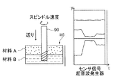
図2Aは、ワークピースWSを超音波加工する工具90の加工操作を概略的に示し、ワークピースWSは異なる材料(材料A及び材料B)の複数の層からなっている。
FIG. 2A schematically shows a machining operation of the
図2Aの右側部分の図表は、ピエゾ要素21の対応したセンサ信号(振幅、周波数、強度)を示し、該図表は、自由に振動可能な(即ち、減衰無しの)振動系と材料A内への進入による減衰振動系との間の差異を既に示す。
The diagram in the right part of FIG. 2A shows the corresponding sensor signals (amplitude, frequency, intensity) of the
材料A内に進入するとき、振動系は一定の振幅を発生するために、より大きなパワーを備えていなければならない。しかしながら、振動系が材料Aで減衰されるために同時に、振動系の共振周波数は低周波数に向けて変化する。 When entering material A, the vibration system must have more power in order to generate a constant amplitude. However, since the vibration system is attenuated by the material A, at the same time, the resonance frequency of the vibration system changes toward a low frequency.
図2Bは、超音波加工のために第2材料B内に工具90が進入した後の加工操作を概略的に示す。該加工において、ピエゾ要素21のセンサ信号は、図2Bの右側部分の図表に示されるように変化する。
FIG. 2B schematically shows the machining operation after the
センサ信号の変化に基づき、第1に、ワークピース内での材料の変化を同定でき、そして、好ましくは、検出されたセンサ信号及び/又は材料変化の同定に基づき、速度、切削速度及び/又は工具の送り等の加工パラメータを、ピエゾ要素21に対する駆動信号パラメータ等の振動パラメータと共に調整可能にする。
Based on sensor signal changes, first, material changes in the workpiece can be identified, and preferably based on detected sensor signals and / or identification of material changes, speed, cutting speed and / or Machining parameters such as tool feed can be adjusted together with vibration parameters such as drive signal parameters for the
図3は、本発明に係る方法の実施形態の流れ図を示す。ここでは、工程S2の初期にて、工具90が所定の加工パラメータに基づき操作される。次の工程(S3)にて、工具90の超音波振動がピエゾ要素21によって発生され、ここで、ピエゾ電気センサ要素40における振幅、周波数及び強度等のセンサ信号が同時に検出される(工程S4)。
FIG. 3 shows a flow chart of an embodiment of the method according to the invention. Here, at the initial stage of step S2, the
次の工程S5において、検出されたセンサ信号が今、初めて評価される。ここでは、例えば、検出されたセンサ信号が(信号ノイズ領域にて)実質的に一定であるか否かが判別される。ここでの判別結果が否の場合、各センサ信号の経時的な変化tが工程S6にて検出される。即ち、センサ信号の変化の速さの程度やセンサ信号の値変化y、つまり、対応する信号の変化の程度又は量が同時に検出される。 In the next step S5, the detected sensor signal is now evaluated for the first time. Here, for example, it is determined whether or not the detected sensor signal is substantially constant (in the signal noise region). If the determination result is NO, a change t with time of each sensor signal is detected in step S6. That is, the degree of change of the sensor signal and the value change y of the sensor signal, that is, the degree or amount of change of the corresponding signal are simultaneously detected.
これらの検出された値は、次の2つの工程S7,S8にて所定の制限値tgrenz,ygrenzと比較されて、ここでの比較により、材料の変化の有無が決定可能となる。 These detected values are compared with predetermined limit values t grenz and y grenz in the next two steps S7 and S8, and by this comparison, it is possible to determine whether or not the material has changed.
工程S7にて、経時的な変化tが先ず、その目的のための所定の制限値tgrenzと比較される。 In step S7, the change t with time is first compared with a predetermined limit value t grenz for that purpose.
検出された経時的な変化tが所定の制限値tgrenzよりも低いならば、次の工程S8にて、値yの変化量に関して或る比較が実施される。この目的のため、検出された値変化yが所定の制限値ygrenzと比較される。検出された値変化yが所定の制限値ygrenzを超えるなら、検出されたセンサ信号はワークピースWSの材料の変化を示す。 If the detected change t with time is lower than a predetermined limit value t grenz , a comparison is performed with respect to the amount of change of the value y in the next step S8. For this purpose, the detected value change y is compared with a predetermined limit value y grenz . If the detected value change y exceeds a predetermined limit value y grenz , the detected sensor signal indicates a change in the material of the workpiece WS.
上述の記載は例えば、検出された値が工具ホルダに発生された振動の周波数及び/又は検出された超音波変換器20のパワーを含むという事実を参照できる。
The above description can refer, for example, to the fact that the detected values include the frequency of vibrations generated in the tool holder and / or the power of the
該事実に基づき、工程S9にて、所定の処理パラメータが調整される。ここでの調整には、工具における送り速度の調整又は変化、及び/又は、ワークピースが加工される際の工具の切削速度又は回転速度を含むことができる。 Based on this fact, predetermined process parameters are adjusted in step S9. The adjustment here may include adjustment or change of the feed rate in the tool and / or the cutting speed or rotational speed of the tool as the workpiece is machined.
ここで、パラメータは次のようにして調整される。ピエゾ電気センサ要素40のセンサ信号を検出し、センサ信号は例えば、相応の既知の材料に関して、既に検出されたセンサ信号を含むデータセットと比較される。
Here, the parameters are adjusted as follows. The sensor signal of the
これらデータセットは例えば、工具と材料との組み合わせにおける共振周波数又は材料の減衰能力を含むことができ、(「指紋」の一種として)全ての既知の材料の特性である。ここで、適合が決定されたなら、現在の材料が同定されて、これに基づき、加工パラメータは対応の材料に順応可能である。 These data sets can include, for example, the resonance frequency or material damping capability of the tool and material combination, and are characteristics of all known materials (as a kind of “fingerprint”). Here, if a match is determined, the current material is identified and based on this, the processing parameters can adapt to the corresponding material.
しかしながら、既知でない材料があれば、その材料の種類及び/又は材料の硬度の程度及び減衰能力は、検出されたセンサ信号に基づいて評価可能であり、そして、これに基づき、加工パラメータが調整可能である。それ故、一例として、材料の分類も可能となる。 However, if there is an unknown material, the material type and / or the degree of hardness and the damping capacity of the material can be evaluated based on the detected sensor signal, and the processing parameters can be adjusted based on this It is. Therefore, as an example, the material can be classified.
また、ワークピースが既知の材料組成を有する場合、ワークピースの種々の材料又は材料層のために、種々の加工パラメータ又は加工パラメータセットを予め決定することができ、そして、ワークピースの材料変化が工具の工具尖端位置で同定されたとき、加工パラメータは異なる所定の加工パラメータ又は加工パラメータセットに順応される。 Also, if the workpiece has a known material composition, different processing parameters or sets of processing parameters can be predetermined for different materials or material layers of the workpiece, and workpiece material changes When identified at the tool tip position of the tool, the machining parameters are adapted to different predefined machining parameters or machining parameter sets.
しかしながら、工程S8にて、対応のセンサ信号の値変化yが所定の制限値ygrenzを超えないならば、方法は加工パラメータを変更せずに続けられる。 However, if, in step S8, the value change y of the corresponding sensor signal does not exceed the predetermined limit value y grenz , the method is continued without changing the machining parameters.
図4は本発明に係る装置を概略的に示し、該装置によって本発明の方法が実施可能である。 FIG. 4 schematically shows a device according to the invention, by which the method according to the invention can be carried out.
装置は工作機械1000の一部である。図4は、ピエゾ電気センサ要素40を有した工具ホルダ10を示し、該工具ホルダ10の構成は図1に一例として示された工具ホルダ10の構成に相当する。工具ホルダ10にはワークピースを超音波加工する工具90が受け取られている。
The apparatus is part of the
工具ホルダ10において、発生器120はピエゾ駆動部の駆動信号として、作業信号A1を出力する。作業信号A1は作業周波数f1を有し、回転する工具ホルダ10に向けて、エネルギ発生装置30を介してパワーP1と共に非接触に転送され、該エネルギ発生装置30は、第1ポットコア31を備えた一次巻線32及び第2ポットコア33を備えた二次巻線からなっている。更にまた、発生器120は、パワーPt<P1のテスト信号Atを出力し、該テスト信号Atは作業信号A1に重畳され、その周波数はf1の範囲内で変化する。
In the
信号A1,Atのために、工具ホルダ10の振動系は振動すべく誘起され、該振動の周波数スペクトルは実質的に2つの周波数を有する。
Due to the signals A1, At, the vibration system of the
振動系の振動のために、ピエゾ電気センサ要素40もまた同様に振動し、電気的なセンサ信号A2を発生する。該センサ信号A2は振動の周波数スペクトルに関係した情報を含んでいる。
Due to the vibration of the vibration system, the
センサ信号A2は例えば、他の変圧器を介して回転中の工具ホルダ10から読み出し装置130によって非接触にして読み出され、そして、解析装置140aに転送される。他の変圧器は第1鉄心61を備えた一次巻線62と第2鉄心81を備えた二次巻線82からなっている。
The sensor signal A2 is read out in a non-contact manner by the
解析装置140aは、センサ信号A2の周波数スペクトルに含まれる周波数を同定し、それ故、共振周波数を決定する装置140bにて、スペクトルの最大ピークの周波数(主要周波数)が作業周波数f1と関連付け可能であり、該装置140bは解析装置140aの一部として実現可能である。スペクトル中のより小さいピークの周波数(補助周波数)は共振周波数f2と関連付け可能である。また、読み出し装置130、解析装置140a及び共振周波数決定用装置140bは2つの装置に結合されるか、又は単一の装置としても実現可能である。
The
決定された共振周波数f2の値は第1制御装置150に伝送され、該第1制御装置150は作業信号A1の周波数f1が共振周波数f2に調整されるべく発生器120を制御する。
The determined value of the resonance frequency f2 is transmitted to the
代替的又は付加的には、決定された共振周波数f2の値は第2制御装置160に伝送可能であり、該第2制御装置160は、工具ホルダ10に作業信号A1を発生(irradiate)するパワーP1がパワーP1’に増加されるべく発生器120を制御し、これにより、f1≠f2の励振(excitation)の場合でさえも、機械的な振動の振幅が得られ、ここでの振幅は共振周波数f2で励振された最大振幅として達成される。
Alternatively or additionally, the value of the determined resonance frequency f2 can be transmitted to the
従って、工具90での加工中、工具尖端での機械的振動の振幅を精度に関してプラス効果を有した或る値に安定させることが可能となる。或るパワーでの場合に、振動の振幅が可能な最大値に安定されたとき、ワークピースの加工効率もまた増加される。
Therefore, during machining with the
装置のユーザはユーザインタフェース170を介して第1制御装置150及び/又は第2制御装置160を制御でき、これより、作業信号A1はユーザの指令又は所定の条件が付与されたときのみに調整される。また、ユーザは、決定された最新の共振周波数f2に基づき、作業信号A1が規則的又は不規則な間隔で自動的に調整されるべく決定可能である。
The user of the device can control the
発生器120、読み出し装置(又は検出装置)130、解析装置140a及び第1制御装置150は、1つ装置200に結合でき、該装置200は複数の出力信号を出力し且つ複数の入力信号を受け取る。ここで、装置200の第1出力信号は作業信号A1に相当し、第2出力信号はテスト信号Atに相当し、そして、1つの入力信号はセンサ信号A2に相当する。
The
上述の実施形態において、工具の振動は振動系の各自の共振周波数によって制御可能である。工具又は工具尖端が2つの材料の境界に位置付けられたとき、制御された共振周波数又はその結果、パワーが変化するなら、その変化は本発明の実施形態に従い、材料の変化を検出するため使用可能である。 In the above embodiment, the vibration of the tool can be controlled by the respective resonance frequency of the vibration system. If the tool or tool tip is positioned at the boundary between two materials, and if the controlled resonant frequency or consequent power changes, then that change can be used to detect material changes in accordance with embodiments of the present invention. It is.
一方、このことは、ワークピースにおける2つの材料層間の境界が同定できることである。しかしながら、例えばワークピース内又はワークピースの表面に空気、空洞、ボア等が存在する場合、例えばワークピースとの最初の接触を検出するために、前記境界はまたワークピースの材料間(ワークピース表面と空気との間)の境界ともなる。 On the other hand, this is that the boundary between the two material layers in the workpiece can be identified. However, if there are air, cavities, bores, etc. in the workpiece or on the surface of the workpiece, for example, to detect the first contact with the workpiece, the boundary is also between the workpiece materials (workpiece surface And the air).
本発明の実施形態及びその利点は添付図面を参照して詳細に上述されている。 Embodiments of the present invention and their advantages have been described in detail above with reference to the accompanying drawings.
しかしながら、本発明が上述の実施形態や構成上の特徴に限定又は制約されるものでなく、独立請求項の範囲内で、構成上の特徴の変形、特に、上述の実施形態の特徴の変形又は上述の実施形態の個々又は複数の特徴の組み合わせを含むことに再度留意すべきである。 However, the present invention is not limited or restricted to the above-described embodiments and structural features, and within the scope of the independent claims, modifications of the structural features, in particular, It should be noted again that it includes a combination of individual or multiple features of the above-described embodiments.
Claims (13)
ワークピースの加工のためにワークピースに対する工具の相対移動を制御し、
超音波発生器によって工具に超音波振動を発生させ、
前記超音波発生器から出力された少なくとも1つのセンサ信号を検出し、
前記超音波発生器から出力された前記少なくとも1つのセンサ信号に基づき、ワークピースに対する工具の相対移動を制御しながら、前記ワークピースでの材料の変化を同定し、
ワークピースに対する工具の相対移動の制御は、所定の加工パラメータに基づいて実施され、
「ワークピースにて材料の変化を同定する」工程にて、前記超音波発生器におけるセンサ信号の1つ以上のパラメータの値の経時的な変化及び同時的な変化が付加的に検出され、
更に、前記超音波発生器における少なくとも1つのセンサ信号の値の前記経時的な変化及び前記同時的な変化が相応に所定の変更時間未満内にあり且つ同時に所定の変更値を超えるか否かを決定し、
前記超音波発生器における少なくとも1つのセンサ信号の値の前記経時的な変化及び前記同時的な変化が相応に所定の変更時間未満内にあり且つ同時に所定の変更値を超えるとき、予め決定された加工パラメータが調整される、方法。 A method of machining a workpiece with a tool in a numerically controlled machine tool,
Control the relative movement of the tool with respect to the workpiece for machining the workpiece,
The ultrasonic generator generates ultrasonic vibrations on the tool,
Detecting at least one sensor signal output from the ultrasonic generator;
Based on the at least one sensor signal output from the ultrasonic generator, identifying a material change in the workpiece while controlling the relative movement of the tool with respect to the workpiece ;
Control of the relative movement of the tool with respect to the workpiece is performed based on predetermined machining parameters,
In the step of “identifying material changes in the workpiece”, a change in the value of one or more parameters of the sensor signal in the ultrasonic generator over time and a simultaneous change are additionally detected,
Further, whether the change over time and the simultaneous change of the value of at least one sensor signal in the ultrasonic generator are correspondingly within a predetermined change time and simultaneously exceed a predetermined change value. Decide
Predetermined when the time-dependent change and the simultaneous change in the value of at least one sensor signal in the ultrasonic generator are correspondingly within a predetermined change time and simultaneously exceed a predetermined change value Method in which machining parameters are adjusted .
ワークピースの1つの材料領域から別の材料領域へのワークピースの変わり目は、「ワークピースにて材料の変化を同定する」工程にて同定される、請求項1に記載の方法。 The workpiece includes at least two different material regions;
The method of claim 1, wherein a workpiece transition from one material region to another material region of the workpiece is identified in the step of “identifying material changes at the workpiece”.
前記工作機械は、ワークピースを加工するために、ワークピースに対する工具の相対移動を制御する制御ユニットと、工具に超音波振動を発生させる超音波発生器と、該超音波発生器から出力された少なくとも1つのセンサ信号を検出する検出ユニットとを含み、
前記装置は、前記超音波発生器から出力された少なくとも1つのセンサ信号に基づき、ワークピースに対する工具の相対移動を制御しながらワークピースでの材料の変化を同定する評価ユニットを含む、装置。 In order to machine a workpiece with a tool, in particular an apparatus used in a machine tool according to the method according to claim 1 ,
In order to process the workpiece, the machine tool controls a relative movement of the tool with respect to the workpiece, an ultrasonic generator that generates ultrasonic vibrations in the tool, and an output from the ultrasonic generator A detection unit for detecting at least one sensor signal;
The apparatus includes an evaluation unit that identifies material changes in the workpiece while controlling relative movement of the tool relative to the workpiece based on at least one sensor signal output from the ultrasound generator.
ワークピースを加工するためにワークピースに対する工具の相対移動を制御する制御ユニットと、
超音波発生器によって工具に超音波振動を発生させる超音波発生器と、
前記超音波発生器から出力された少なくとも1つのセンサ信号を検出する検出ユニットと
を備えた工作機械において、
請求項11に記載の装置を具備する、工作機械。 A machine tool for machining a workpiece with a tool,
A control unit for controlling the relative movement of the tool with respect to the workpiece in order to machine the workpiece;
An ultrasonic generator for generating ultrasonic vibrations on the tool by the ultrasonic generator;
In a machine tool comprising a detection unit for detecting at least one sensor signal output from the ultrasonic generator,
A machine tool comprising the apparatus according to claim 11 .
前記コンピュータプログラムが前記工作機械にて請求項1〜10の何れかに記載の方法を実行すべく構成されている、コンピュータプログラム製品。 A computer program comprising a computer program stored in a computer readable data storage medium, the computer program being executable by a computer connected to a numerical control machine tool or a numerical control machine tool control unit Product,
A computer program product, wherein the computer program is configured to execute the method according to any of claims 1 to 10 on the machine tool.
Applications Claiming Priority (2)
| Application Number | Priority Date | Filing Date | Title |
|---|---|---|---|
| DE102016214699.8A DE102016214699A1 (en) | 2016-08-08 | 2016-08-08 | Method and device for machining a workpiece on a numerically controlled machine tool |
| DE102016214699.8 | 2016-08-08 |
Publications (3)
| Publication Number | Publication Date |
|---|---|
| JP2018039107A JP2018039107A (en) | 2018-03-15 |
| JP2018039107A5 JP2018039107A5 (en) | 2019-07-11 |
| JP6619399B2 true JP6619399B2 (en) | 2019-12-11 |
Family
ID=59649494
Family Applications (1)
| Application Number | Title | Priority Date | Filing Date |
|---|---|---|---|
| JP2017149869A Active JP6619399B2 (en) | 2016-08-08 | 2017-08-02 | Method, apparatus, machine tool, and computer program product for machining a workpiece with a numerically controlled machine tool |
Country Status (10)
| Country | Link |
|---|---|
| US (1) | US10678219B2 (en) |
| EP (1) | EP3281741B1 (en) |
| JP (1) | JP6619399B2 (en) |
| CN (1) | CN107695793B (en) |
| CA (1) | CA2975574C (en) |
| DE (1) | DE102016214699A1 (en) |
| ES (1) | ES2904283T3 (en) |
| PL (1) | PL3281741T3 (en) |
| PT (1) | PT3281741T (en) |
| RU (1) | RU2700628C2 (en) |
Families Citing this family (8)
| Publication number | Priority date | Publication date | Assignee | Title |
|---|---|---|---|---|
| DE102017208909A1 (en) | 2017-05-26 | 2018-11-29 | Trumpf Werkzeugmaschinen Gmbh + Co. Kg | A method for determining material properties of a workpiece by audio analysis of a workpiece processing and punching machine and computer program product |
| MX2020007787A (en) | 2018-01-23 | 2020-10-14 | Quantum Impact Llc | Method and apparatus for machining a workpiece. |
| CN109894923B (en) * | 2019-03-07 | 2020-11-27 | 中南大学 | Cutter stability control method in ultrasonic vibration auxiliary machining |
| DE102019003921B4 (en) * | 2019-06-05 | 2021-05-06 | Hufschmied Zerspanungssysteme Gmbh | Workpiece inspection method and workpiece inspection system |
| DE102019209191A1 (en) * | 2019-06-25 | 2020-12-31 | Sauer Gmbh | METHOD AND DEVICE FOR CONTROLLING AN ULTRASONIC TOOL UNIT FOR MACHINING ON A MACHINE TOOL |
| CN111843615B (en) * | 2020-06-29 | 2021-07-20 | 中南大学 | Method for rapidly identifying fracture toughness of material in ultrasonic vibration-assisted machining |
| CN113714856B (en) * | 2021-07-26 | 2023-06-27 | 豪丰茂五金制品(太仓)有限公司 | Ultrasonic automatic detection system of numerical control machine tool and working method thereof |
| WO2023179844A1 (en) | 2022-03-22 | 2023-09-28 | Schunk Sonosystems Gmbh | Method for controlling an ultrasonic generator, and ultrasonic generator |
Family Cites Families (28)
| Publication number | Priority date | Publication date | Assignee | Title |
|---|---|---|---|---|
| GB8810976D0 (en) | 1988-05-10 | 1988-06-15 | Sra Dev Ltd | Cutting brittle materials |
| US5257531A (en) * | 1992-08-17 | 1993-11-02 | Masashi Motosugi | Apparatus for monitoring machining state of drill |
| US5940787A (en) * | 1993-12-10 | 1999-08-17 | U.S. Tech Corporation | Apparatuses and methods of monitoring the condition of tools and workpieces |
| TW320591B (en) * | 1995-04-26 | 1997-11-21 | Fujitsu Ltd | |
| US5808396A (en) * | 1996-12-18 | 1998-09-15 | Alcon Laboratories, Inc. | System and method for tuning and controlling an ultrasonic handpiece |
| US6051500A (en) * | 1998-05-19 | 2000-04-18 | Lucent Technologies Inc. | Device and method for polishing a semiconductor substrate |
| DE19960824C2 (en) * | 1999-12-16 | 2003-08-21 | Hilti Ag | Method and device for examining and identifying the type of subsurface |
| US6637986B2 (en) * | 2001-11-26 | 2003-10-28 | Delphi Technologies, Inc. | Drilling apparatus and method |
| JP2005224891A (en) * | 2004-02-12 | 2005-08-25 | Kyoritsu Seiki Kk | Drill holder |
| ATE395999T1 (en) | 2004-07-02 | 2008-06-15 | Sauer Gmbh | SWING HEAD TOOL |
| EP1669148B1 (en) * | 2004-12-13 | 2018-01-17 | Fritz Studer AG | Tool-unit for ultrasonic rotational machining |
| JP2008140037A (en) * | 2006-11-30 | 2008-06-19 | Matsushita Electric Works Ltd | Working monitoring device |
| DE102007013055B4 (en) * | 2007-03-19 | 2015-11-26 | Sauer Ultrasonic Gmbh | Method and device for determining the frequency characteristic and for operating an ultrasonic tool |
| DE102007042280A1 (en) * | 2007-09-06 | 2009-03-12 | Komet Group Holding Gmbh | Drilling tool for machine tools and method for its production |
| US8180479B2 (en) * | 2008-02-05 | 2012-05-15 | The Boeing Company | Adaptive control of composite plycutting |
| US8317437B2 (en) * | 2008-08-01 | 2012-11-27 | The Boeing Company | Adaptive positive feed drilling system |
| FR2944722B1 (en) * | 2009-04-28 | 2014-10-10 | Arts | AXIAL VIBRATION DRILLING HEAD |
| JP5622463B2 (en) * | 2010-07-09 | 2014-11-12 | 株式会社スギノマシン | Drilling control method and drilling apparatus |
| JP5573459B2 (en) * | 2010-07-27 | 2014-08-20 | 株式会社ジェイテクト | Grinding method and grinding machine |
| DE102010048636B4 (en) * | 2010-10-15 | 2017-11-16 | Sauer Ultrasonic Gmbh | Machine tool and method for machining a workpiece with a tool |
| JP5747576B2 (en) * | 2011-03-11 | 2015-07-15 | トヨタ紡織株式会社 | Ultrasonic cutting device and method for manufacturing vehicle interior material using the same |
| EP2803455A1 (en) | 2013-05-13 | 2014-11-19 | A O Schallinox GmbH | Device for cutting a process material |
| CN104552422A (en) * | 2013-10-29 | 2015-04-29 | 青岛天恒机械有限公司 | Ultrasonic assisted machining technology for composite materials |
| CN104647147A (en) * | 2013-11-25 | 2015-05-27 | 大连康赛谱科技发展有限公司 | Carbon fiber composite rotary ultrasonic milling and grinding device and method |
| KR101561531B1 (en) * | 2014-04-25 | 2015-11-02 | 한국기계연구원 | Ultrasonic milling machine |
| DE102015105338A1 (en) * | 2015-04-08 | 2016-10-27 | Lti Motion Gmbh | Tool drive with spindle shaft and operating method |
| JP6695102B2 (en) * | 2015-05-26 | 2020-05-20 | 株式会社ディスコ | Processing system |
| US10232446B2 (en) * | 2015-11-16 | 2019-03-19 | Apex Brands, Inc. | Adaptive drilling with piezo-electric feed oscillator |
-
2016
- 2016-08-08 DE DE102016214699.8A patent/DE102016214699A1/en not_active Ceased
-
2017
- 2017-08-02 JP JP2017149869A patent/JP6619399B2/en active Active
- 2017-08-04 RU RU2017127899A patent/RU2700628C2/en active
- 2017-08-04 CA CA2975574A patent/CA2975574C/en not_active Expired - Fee Related
- 2017-08-08 EP EP17185214.8A patent/EP3281741B1/en active Active
- 2017-08-08 PT PT171852148T patent/PT3281741T/en unknown
- 2017-08-08 PL PL17185214T patent/PL3281741T3/en unknown
- 2017-08-08 US US15/671,517 patent/US10678219B2/en active Active
- 2017-08-08 ES ES17185214T patent/ES2904283T3/en active Active
- 2017-08-08 CN CN201710672201.XA patent/CN107695793B/en active Active
Also Published As
| Publication number | Publication date |
|---|---|
| JP2018039107A (en) | 2018-03-15 |
| EP3281741B1 (en) | 2021-12-15 |
| CA2975574A1 (en) | 2018-02-08 |
| PT3281741T (en) | 2022-02-14 |
| CN107695793A (en) | 2018-02-16 |
| DE102016214699A1 (en) | 2018-02-08 |
| CA2975574C (en) | 2019-06-18 |
| US20180039255A1 (en) | 2018-02-08 |
| US10678219B2 (en) | 2020-06-09 |
| RU2017127899A3 (en) | 2019-02-04 |
| ES2904283T3 (en) | 2022-04-04 |
| RU2017127899A (en) | 2019-02-04 |
| RU2700628C2 (en) | 2019-09-19 |
| CN107695793B (en) | 2021-11-23 |
| EP3281741A1 (en) | 2018-02-14 |
| PL3281741T3 (en) | 2022-03-07 |
Similar Documents
| Publication | Publication Date | Title |
|---|---|---|
| JP6619399B2 (en) | Method, apparatus, machine tool, and computer program product for machining a workpiece with a numerically controlled machine tool | |
| JP6718953B2 (en) | Method and device for measuring the resonant frequency of a tool set in an ultrasonic vibration state for machining | |
| JP6616488B2 (en) | Device for generating ultrasonic vibrations of tools and measuring vibration parameters | |
| US10821568B2 (en) | Method and device for determining a vibration amplitude of a tool | |
| JP6223237B2 (en) | Cutting equipment | |
| JP6223239B2 (en) | Cutting equipment | |
| JP2018039107A5 (en) | ||
| US20040236529A1 (en) | Active electromagnetic device for measuring the dynamic response of a tool in a CNC machine | |
| JP4614337B2 (en) | Tool tip position detection method, workpiece machining method, and wear state detection method | |
| JP7324219B2 (en) | Smart ultrasound stack and method of controlling an ultrasound system having a smart ultrasound stack | |
| JP7346085B2 (en) | System and method for determining structural characteristics of machine tools | |
| JPWO2007080692A1 (en) | AE sensor and AE sensor operation state confirmation method | |
| JP2022538434A (en) | Method and apparatus for controlling ultrasonic tool units for machining on machine tools | |
| JP6223238B2 (en) | Cutting equipment | |
| TW202024579A (en) | Method of measuring ultrasonic vibration of a rotating object during processing and ultrasonic vibration measurement module | |
| WO2023047087A1 (en) | Method of operating a machine tool apparatus | |
| RU2379737C2 (en) | Method of maintaining acceptable technological modes |
Legal Events
| Date | Code | Title | Description |
|---|---|---|---|
| A621 | Written request for application examination |
Free format text: JAPANESE INTERMEDIATE CODE: A621 Effective date: 20171221 |
|
| A977 | Report on retrieval |
Free format text: JAPANESE INTERMEDIATE CODE: A971007 Effective date: 20181130 |
|
| A131 | Notification of reasons for refusal |
Free format text: JAPANESE INTERMEDIATE CODE: A131 Effective date: 20181212 |
|
| A601 | Written request for extension of time |
Free format text: JAPANESE INTERMEDIATE CODE: A601 Effective date: 20190311 |
|
| A601 | Written request for extension of time |
Free format text: JAPANESE INTERMEDIATE CODE: A601 Effective date: 20190510 |
|
| A524 | Written submission of copy of amendment under article 19 pct |
Free format text: JAPANESE INTERMEDIATE CODE: A524 Effective date: 20190607 |
|
| TRDD | Decision of grant or rejection written | ||
| A01 | Written decision to grant a patent or to grant a registration (utility model) |
Free format text: JAPANESE INTERMEDIATE CODE: A01 Effective date: 20191030 |
|
| A61 | First payment of annual fees (during grant procedure) |
Free format text: JAPANESE INTERMEDIATE CODE: A61 Effective date: 20191114 |
|
| R150 | Certificate of patent or registration of utility model |
Ref document number: 6619399 Country of ref document: JP Free format text: JAPANESE INTERMEDIATE CODE: R150 |
|
| R250 | Receipt of annual fees |
Free format text: JAPANESE INTERMEDIATE CODE: R250 |
|
| R250 | Receipt of annual fees |
Free format text: JAPANESE INTERMEDIATE CODE: R250 |