EP3279614A1 - Positionsmesseinrichtung und verfahren zum betreiben einer positionsmesseinrichtung - Google Patents
Positionsmesseinrichtung und verfahren zum betreiben einer positionsmesseinrichtung Download PDFInfo
- Publication number
- EP3279614A1 EP3279614A1 EP17169506.7A EP17169506A EP3279614A1 EP 3279614 A1 EP3279614 A1 EP 3279614A1 EP 17169506 A EP17169506 A EP 17169506A EP 3279614 A1 EP3279614 A1 EP 3279614A1
- Authority
- EP
- European Patent Office
- Prior art keywords
- signal
- unit
- signals
- scanning
- measuring device
- Prior art date
- Legal status (The legal status is an assumption and is not a legal conclusion. Google has not performed a legal analysis and makes no representation as to the accuracy of the status listed.)
- Granted
Links
Images


Classifications
-
- G—PHYSICS
- G01—MEASURING; TESTING
- G01B—MEASURING LENGTH, THICKNESS OR SIMILAR LINEAR DIMENSIONS; MEASURING ANGLES; MEASURING AREAS; MEASURING IRREGULARITIES OF SURFACES OR CONTOURS
- G01B21/00—Measuring arrangements or details thereof, where the measuring technique is not covered by the other groups of this subclass, unspecified or not relevant
-
- G—PHYSICS
- G01—MEASURING; TESTING
- G01D—MEASURING NOT SPECIALLY ADAPTED FOR A SPECIFIC VARIABLE; ARRANGEMENTS FOR MEASURING TWO OR MORE VARIABLES NOT COVERED IN A SINGLE OTHER SUBCLASS; TARIFF METERING APPARATUS; MEASURING OR TESTING NOT OTHERWISE PROVIDED FOR
- G01D5/00—Mechanical means for transferring the output of a sensing member; Means for converting the output of a sensing member to another variable where the form or nature of the sensing member does not constrain the means for converting; Transducers not specially adapted for a specific variable
- G01D5/12—Mechanical means for transferring the output of a sensing member; Means for converting the output of a sensing member to another variable where the form or nature of the sensing member does not constrain the means for converting; Transducers not specially adapted for a specific variable using electric or magnetic means
- G01D5/244—Mechanical means for transferring the output of a sensing member; Means for converting the output of a sensing member to another variable where the form or nature of the sensing member does not constrain the means for converting; Transducers not specially adapted for a specific variable using electric or magnetic means influencing characteristics of pulses or pulse trains; generating pulses or pulse trains
- G01D5/245—Mechanical means for transferring the output of a sensing member; Means for converting the output of a sensing member to another variable where the form or nature of the sensing member does not constrain the means for converting; Transducers not specially adapted for a specific variable using electric or magnetic means influencing characteristics of pulses or pulse trains; generating pulses or pulse trains using a variable number of pulses in a train
- G01D5/2454—Encoders incorporating incremental and absolute signals
- G01D5/2455—Encoders incorporating incremental and absolute signals with incremental and absolute tracks on the same encoder
- G01D5/2457—Incremental encoders having reference marks
-
- G—PHYSICS
- G01—MEASURING; TESTING
- G01D—MEASURING NOT SPECIALLY ADAPTED FOR A SPECIFIC VARIABLE; ARRANGEMENTS FOR MEASURING TWO OR MORE VARIABLES NOT COVERED IN A SINGLE OTHER SUBCLASS; TARIFF METERING APPARATUS; MEASURING OR TESTING NOT OTHERWISE PROVIDED FOR
- G01D3/00—Indicating or recording apparatus with provision for the special purposes referred to in the subgroups
- G01D3/08—Indicating or recording apparatus with provision for the special purposes referred to in the subgroups with provision for safeguarding the apparatus, e.g. against abnormal operation, against breakdown
-
- G—PHYSICS
- G01—MEASURING; TESTING
- G01D—MEASURING NOT SPECIALLY ADAPTED FOR A SPECIFIC VARIABLE; ARRANGEMENTS FOR MEASURING TWO OR MORE VARIABLES NOT COVERED IN A SINGLE OTHER SUBCLASS; TARIFF METERING APPARATUS; MEASURING OR TESTING NOT OTHERWISE PROVIDED FOR
- G01D5/00—Mechanical means for transferring the output of a sensing member; Means for converting the output of a sensing member to another variable where the form or nature of the sensing member does not constrain the means for converting; Transducers not specially adapted for a specific variable
- G01D5/12—Mechanical means for transferring the output of a sensing member; Means for converting the output of a sensing member to another variable where the form or nature of the sensing member does not constrain the means for converting; Transducers not specially adapted for a specific variable using electric or magnetic means
- G01D5/244—Mechanical means for transferring the output of a sensing member; Means for converting the output of a sensing member to another variable where the form or nature of the sensing member does not constrain the means for converting; Transducers not specially adapted for a specific variable using electric or magnetic means influencing characteristics of pulses or pulse trains; generating pulses or pulse trains
- G01D5/24471—Error correction
-
- G—PHYSICS
- G08—SIGNALLING
- G08C—TRANSMISSION SYSTEMS FOR MEASURED VALUES, CONTROL OR SIMILAR SIGNALS
- G08C15/00—Arrangements characterised by the use of multiplexing for the transmission of a plurality of signals over a common path
- G08C15/06—Arrangements characterised by the use of multiplexing for the transmission of a plurality of signals over a common path successively, i.e. using time division
-
- G—PHYSICS
- G01—MEASURING; TESTING
- G01D—MEASURING NOT SPECIALLY ADAPTED FOR A SPECIFIC VARIABLE; ARRANGEMENTS FOR MEASURING TWO OR MORE VARIABLES NOT COVERED IN A SINGLE OTHER SUBCLASS; TARIFF METERING APPARATUS; MEASURING OR TESTING NOT OTHERWISE PROVIDED FOR
- G01D5/00—Mechanical means for transferring the output of a sensing member; Means for converting the output of a sensing member to another variable where the form or nature of the sensing member does not constrain the means for converting; Transducers not specially adapted for a specific variable
- G01D5/12—Mechanical means for transferring the output of a sensing member; Means for converting the output of a sensing member to another variable where the form or nature of the sensing member does not constrain the means for converting; Transducers not specially adapted for a specific variable using electric or magnetic means
- G01D5/244—Mechanical means for transferring the output of a sensing member; Means for converting the output of a sensing member to another variable where the form or nature of the sensing member does not constrain the means for converting; Transducers not specially adapted for a specific variable using electric or magnetic means influencing characteristics of pulses or pulse trains; generating pulses or pulse trains
- G01D5/24428—Error prevention
-
- G—PHYSICS
- G01—MEASURING; TESTING
- G01D—MEASURING NOT SPECIALLY ADAPTED FOR A SPECIFIC VARIABLE; ARRANGEMENTS FOR MEASURING TWO OR MORE VARIABLES NOT COVERED IN A SINGLE OTHER SUBCLASS; TARIFF METERING APPARATUS; MEASURING OR TESTING NOT OTHERWISE PROVIDED FOR
- G01D5/00—Mechanical means for transferring the output of a sensing member; Means for converting the output of a sensing member to another variable where the form or nature of the sensing member does not constrain the means for converting; Transducers not specially adapted for a specific variable
- G01D5/12—Mechanical means for transferring the output of a sensing member; Means for converting the output of a sensing member to another variable where the form or nature of the sensing member does not constrain the means for converting; Transducers not specially adapted for a specific variable using electric or magnetic means
- G01D5/244—Mechanical means for transferring the output of a sensing member; Means for converting the output of a sensing member to another variable where the form or nature of the sensing member does not constrain the means for converting; Transducers not specially adapted for a specific variable using electric or magnetic means influencing characteristics of pulses or pulse trains; generating pulses or pulse trains
- G01D5/24471—Error correction
- G01D5/24476—Signal processing
Definitions
- the present invention relates to a position-measuring device according to claim 1, and to a method for operating a position-measuring device according to claim 6.
- Incremental position measuring devices are used in automation technology and in particular in machine tools to measure changes in position of moving parts.
- incremental encoders measure rotational movements, such as those of rotating shafts.
- Incremental linear encoders measure linear displacements of mutually movably arranged machine parts.
- a graduation track which consists of regularly arranged code elements, of a detector unit scanned.
- the detector signals resulting from the sampling are preferably largely sinusoidal in the case of uniform motion (constant speed or constant rotational speed), the position information can be obtained, for example, by counting the traveled signal periods or, if an increased resolution is required, by dividing the signal periods into a number of times Length or angle segments (interpolation) are obtained.
- Directional information can be obtained when two detector signals are generated during the scan, which have a phase shift, for example 90 ° to one another.
- a reference pulse is often generated at least one position.
- a suitable division structure can be arranged on a separate graduation track, which is also scanned by the detector unit.
- the detector signals obtained by the detector unit are processed in a signal processing unit and adapted according to a specification of an output interface.
- a known interface for incremental position-measuring devices for example, requires a peak-to-peak value of 1 V for the incremental signals.
- the signals are largely sinusoidal at constant speed (speed) and symmetrical about a reference potential (usually ground potential 0V).
- the phase shift between the incremental position signals is 90 °.
- the reference pulse RI is symmetrical and its maximum is at a defined position with respect to the incremental position signals.
- the signal processing unit can compensate for aging-related changes of the detector signals obtained by the detector unit, such as a reduction of the signal amplitudes, within wide limits.
- a disadvantage of this approach is that, when the control limits of the signal processing unit are reached, only a short lead time remains until the position measuring device has to be maintained or replaced.
- the optimization of the detector signals by the signal processing unit complicates the adjustment of the detector unit with respect to the measurement graduation, since optimal position signals can already be obtained even with an as yet imprecise cultivation of faulty detector signals.
- the DE 195 21 252 A1 discloses a position measuring device in which one or more outputs of an output amplifier can be switched to high impedance in the event of a fault. However, this leads to an immediate emergency stop of the plant, so there is no possibility for preventive maintenance.
- a position measuring device comprising a graduation carrier with a measuring graduation, a scanning unit which is arranged to be movable in a measuring direction relative to the measuring graduation, for generating position-dependent scanning signals by sampling the measuring graduation, a signal processing unit for processing the scanning signals to position signals and a signal interface via the the position signals can be output to a subsequent electronics.
- the signal processing unit at least one correction unit is arranged, with which at least one signal error of at least one scanning signal is correctable, and a monitoring unit with the reaching of a limit value of the signal error detectable and subsequently at least the event triggering correction unit can be deactivated.
- a method for operating a position measuring device which has a graduation carrier with a measuring graduation, a scanning unit which is arranged to be movable in a measuring direction relative to the measuring graduation and with which position-dependent scanning signals are generated by sampling the measuring graduation, a signal processing unit in the scanning signals to position signals are processed and a signal interface via which the position signals are output to a subsequent electronics comprises.
- At least one correction unit is arranged in the signal processing unit, with which at least one signal error of at least one scanning signal is corrected, and a monitoring unit with which the reaching of a limit value of the signal error is detected and subsequently at least the correction unit triggering the event is deactivated
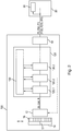
- FIG. 1 shows a block diagram of a position-measuring device 10 according to the invention. It comprises a scanning unit 12, which is designed to scan a measuring graduation on a graduation carrier 14. Division carrier 14 and scanning unit 12 are arranged in a known manner in a measuring direction relative to each other movable, for example, by being connected to moving parts of a machine tool whose relative position is to be determined to each other.
- Both linear (length measuring devices) and rotary position measuring devices can be designed according to the invention.
- the present invention is largely independent of the physical scanning principle.
- an optical, magnetic, capacitive or inductive scanning can be used.
- the measuring graduation consists of an incremental graduation track 16 and a reference graduation track 17.
- the sampling of the graduation 16, 17 results in sampling signals S0, S90, R, the two 90 ° out of phase incremental signals S0, S90 from the sampling of the incremental graduation track 16, and a Reference signal R from the sample of the reference division track 17 include.
- Reine Preprocessing of detector signals take place, for example, a conversion of current into voltage signals.
- the incremental signals S0, S90 are substantially sinusoidal with uniform movement (corresponding to a constant speed) of the measuring graduation with respect to the scanning unit 12.
- the reference signal R serves to provide an absolute reference position for the principle-related relative position measurement of the incremental position-measuring device 10.
- the reference signal R at at least one defined position (or in the case of an angle measuring device at a defined angular position) on a pulse which is referred to as a reference pulse.
- the scanning signals S0, S90, R are supplied to a signal processing unit 20 which processes them into position signals P0, P90, PR.
- the signal processing unit 20 comprises at least one, in the illustrated example, three correction units 20.1, 20.2, 20.3, each suitable for correcting signal errors of at least one of the scanning signals. Specifically, it is an offset correction unit 20.1, an amplitude correction unit 20.2 and a phase correction unit 20.3.
- the offset correction unit 20.1 is used to correct a signal offset of the incremental signals S0, S90, so that the minimum and maximum values of the sinusoidal signals are arranged symmetrically about a reference potential (usually ground potential 0V). It can also be designed to set a rest potential of the reference signal R, that is to say the potential which the reference signal R has, as long as no reference pulse occurs.
- the amplitude correction unit 20.2 serves to amplify the signal amplitudes of the incremental signals to defined values, for example to a peak-to-peak value of 1V.
- amplifier components can be used.
- the amplitude correction unit 20.2 can be designed to set the amplitude of the reference pulse R to a defined value.
- the phase correction unit 20.3 is designed to adjust the phase shift between the incremental signals, for example to 90 °, whereby the direction of movement (direction of rotation) determines which of the signals is leading or lagging.
- the phase correction unit 20.3 can moreover be provided to set the position of the reference pulse relative to the incremental signals, for example such that its maximum is at a position at which the incremental signals have positive values and the same instantaneous value.
- the scanning signals corrected in this way are output as position signals P0, P90, PR via a signal interface 50 to a sequential electronics 80, for example a numerical control of a machine tool.
- a signal interface 50 may comprise driver modules that amplify the position signals P0, P90, PR for output to the subsequent electronics.
- the driver chips may be configured to output the position signals P0, P90, PR both in the polarity generated by the signal processing unit 20 and as inverted position signals P180, P270, IPR.
- a monitoring unit 30 is arranged in the signal processing unit 20. This is designed to determine whether one of the corrected in the correction units 20.1, 20.2, 20.3 signal error of the sampling signals S0, S90, R reaches a limit, or exceeds or falls below. If this is the case, the monitoring unit 30 switches to a signaling mode and deactivates at least the correction unit 20.1, 20.2, 20.3 corresponding to this signal error, wherein deactivation in this exemplary embodiment means that the corresponding correction unit 20.1, 20.2, 20.3 is in a ground state is switched, so no longer performs correction. This has the consequence that the position signals P0, P90, PR at least the Have signal errors, which has led to the switch to the signaling mode.
- the amplitude correction unit 20.2 is deactivated; if the offset of one of the scanning signals S0, S90, R exceeds a limit, then the offset correction unit 20.1 is deactivated, etc ,
- the limit values are advantageously chosen so that the subsequent electronics 80 can still evaluate the position signals P0, P90, PR, i. that the machine on which the position-measuring device 10 is operated remains functional.
- the monitoring unit 30 deactivates all correction units 20.1, 20.2, 20.3 in such an error case, so that the scanning signals S0, S90, R are output as position signals P0, P90, PR.
- switching means 30.1, 30.2, 30.3 are provided for the deactivation of the correction units 20.1, 20.2, 20.3.
- a receiver-side monitoring unit 90 which monitors the position signals P0, P90, PR and determines the sudden change in one or more error variables caused by the disconnection of one or more correction units 20.1, 20.2, 20.3 and indicates to an operator of the installation, for example by issuing a warning message on a monitor.
- the receiver-side monitoring unit 90 can, as in FIG. 1 can be arranged within the subsequent electronics 80, but it can also be a separate device.
- the embodiment according to the invention of a position-measuring device 10 has two practical effects: firstly, the subsequent electronics 80 can be signaled in this way that a rapid failure of the position-measuring device 10 must be expected, or that the position-measuring device 10 has to be maintained in order to prevent a failure. Maintenance may in this case mean that the measuring graduation 16, 17 and / or the scanning unit 12 must be cleaned, or that the position of the scanning unit 12 with respect to the measuring graduation 16, 17 new must be adjusted. Secondly, the signaling mode can be used to be able to optimally adjust the position of the scanning unit 12 with respect to the measuring graduation 16, 17 during commissioning of the position measuring device 10, so that position signals P0, P90, PR which are as accurate as possible are already obtained without correction.
- correction units 20.1, 20.1, 20.3 were always active, a rough positioning of the scanning unit 12 with respect to the measuring graduation would already be sufficient in order to obtain usable position signals P0, P90, PR. However, in this case it may happen that one or more of the scanning signals S0, S90, R only barely comply with the prescribed limit values. An adjustment with active correction units 20.1, 20.1, 20.3 is therefore not practical.
- Switching to the signaling mode can be artificially triggered by attenuating or interrupting the signals used for sampling.
- This can be achieved by the scanning unit 12 is so far removed from the measurement division 16, 17 during commissioning that one or more limits of signal errors reached, or exceeded or fallen below. This is easy to carry out, especially in the case of so-called open-length measuring devices, because scale (graduation carrier 14) and scanning unit 12 are usually supplied and assembled separately.
- Another possibility is to introduce attenuation or interruption means between scanning unit 12 and measuring graduation 16, 17.
- the light path between a light source and corresponding photodetectors may be interrupted by a film, etc.
- a ferromagnetic material may be introduced between the measuring graduation 16, 17 and the magnetic sensors, etc.
- deactivated correction units 20.1, 20.2, 20.3 can only be reactivated by switching the position-measuring device 10 off and on again.
- FIG. 2 shows a further embodiment of a position-measuring device 100 according to the invention. Components already in connection with FIG. 1 have been described, carry the same reference numerals.
- a signal processing unit 120 comprises an offset correction unit 120.1, an amplitude correction unit 120.2 and a phase correction unit 120.3.
- the correction units 120.1, 120.2, 120.3 of the monitoring unit 130 signal the reaching, or exceeding or falling below of a limit value. If this is the case, the monitoring unit 130 in turn deactivates at least the correction unit 120.1, 120.2, 120.3 corresponding to this signal error or also all the correction units 120.1, 120.2, 120.3. However, the deactivation does not take place now by switching off or bypassing the respective correction unit 120.1, 120.2, 120.3, but by overriding the correction function by current control parameters are stored and thus the function of the correction unit 120.1, 120.2, 120.3 is virtually frozen. This has the consequence that the transition to the signaling mode does not directly a change in the position signals P0, P90, PR occurs, but only with a further increase in the signal error, a change is recognizable.
- a correction of signal errors can also be effected by direct action on the scanning unit 12.
- the signal amplitude of the scanning signals S0, S90, R can be increased by increasing the current for the operation of the light source. Even if in this case the scanning signals S0, S90, R are no longer physically measurable, they furthermore include the signals which would be generated by the scanning unit 12 without the influence of the correction units 120.1, 120.2, 120.3. Of course, this also applies to the first embodiment.
- FIG. 3 shows the example of the waveform of the amplitude value A of the incremental sampling signal S0, and the position signal P0 over time the advantages of the two embodiments, based on the FIGS. 1 and 2 were explained.
- the dashed curve traces the position signal P0 according to the embodiment FIG. 1 the dash-dotted curve shows the alternative course of the position signal P0 'according to the example of FIG. 2 ,
- the illustrated curves include, depending on the operating conditions of the position measuring device 10, 100, a period of many years.
- the scanning signal S0 (and also the position signal P0) has an initial amplitude A1.
- the amplitude decreases, in particular in an optical scanning principle by a deterioration of the luminous intensity of the light source or by a continuously increasing contamination of the measuring graduation.
- the limit value A2 is the amplitude value at which the receiver-side monitoring unit 90 detects a reduction in the amplitude on the part of the subsequent electronics 80 and generates a warning signal.
- the limit value A3 is the amplitude value at which the monitoring unit 30 reaches or falls below the position-measuring device 10, 100 in the signaling mode.
- the limit value A4 is finally the smallest amplitude value that can still be evaluated by the subsequent electronics 80. Falling below the limit A4 leads to a failure of the system in which the position measuring device 10, 100 is operated.
- the sampling signal S0 now reaches the limit value A3, and the position-measuring device 10, 100 switches to the signaling mode and deactivates the amplitude correction unit 20.2 or 120.2.
- the position measuring device 10 which according to the embodiment of FIG. 1 is configured, to a sudden reduction of the position signal P0, due to a shortfall of the Limit value A2 is immediately recognized by the subsequent electronics 80.
- the position measuring device 10 can still be operated until the time t3, so that sufficient time remains to wait or exchange the position measuring device 10 in the course of a normal maintenance interval.
- the position signal P0 In the position measuring device 100 according to the embodiment of FIG. 2 on the other hand, the position signal P0 'largely follows the course of the sampling signal S0 from the time of switching and reaches the limit value A2 only at a time t2. Again, until the failure of the position measuring device 100 at time t4 sufficient time for their maintenance or replacement remains. Since the reduction of the amplitude of sampling signals S0 tends to accelerate towards the end of the life, the time between times t2 and t4 is shorter than the time between times t1 and t3 of the first embodiment. On the other hand, the end of life of the position measuring device 10 of the first embodiment at time t3 is reached earlier than the end of the life of the position measuring device 100 of the second embodiment.
- the correction unit 20.1, 20.2, 20.3, 120.1, 120.2, 120.3 were operated until their control limit was reached, the time between recognition of an impending malfunction and reaching the end of life of the position-measuring device 10, 100 would be shortened to the extent that a reaction in the form of a Maintenance or replacement within a standard maintenance interval would no longer be possible.
- a further improvement of the position measuring device 100 can be achieved if in the example of FIG. 2 the monitoring unit 130 is additionally designed to be capable of generating, upon reaching a second limit value A5 (at the instant t5), at least the correction unit triggering the event (in the example of FIG FIG. 3 the amplitude correction unit 120.2) again with a setpoint of the control, which represents a poorer signal quality of the position signals P0, P90, PR. in the In this way, the amplitude of the position signal P0 "at the level of the second limit value A5 can be reached until reaching the setpoint value of the control to the second limit A5 so that the alternative amplitude characteristic of the position signal P0" shown in FIG the control limit are held at time t6. After this time, the amplitude of the position signal P0 "drops rapidly and reaches the limit value A4 for the safe operation of the system at time t7.
- the reaching of the second limit value A5 can naturally also be effected by monitoring the sampling signal S0.
- this method can be used adapted to other signal errors and can also be mapped to the first embodiment.
- the signal processing unit 20, 120 is advantageously at least partially as a programmable device (FPGA) or application-specific integrated Circuit (ASIC) executed. Likewise, it is advantageous to implement functions of the signal processing unit 20, 120 in whole or in part by the use of a microprocessor, in particular a signal processor. In addition to the functions described, the signal processing unit 20, 120 can still carry out processing steps.
- FPGA programmable device
- ASIC application-specific integrated Circuit
Landscapes
- Physics & Mathematics (AREA)
- General Physics & Mathematics (AREA)
- Transmission And Conversion Of Sensor Element Output (AREA)
- Vehicle Body Suspensions (AREA)
- Basic Packing Technique (AREA)
- Body Structure For Vehicles (AREA)
Abstract
Description
- Die vorliegende Erfindung betrifft eine Positionsmesseinrichtung gemäß Anspruch 1, sowie ein Verfahren zum Betreiben einer Positionsmesseinrichtung gemäß Anspruch 6.
- Inkrementale Positionsmesseinrichtungen werden in der Automatisierungstechnik und insbesondere bei Werkzeugmaschinen dazu eingesetzt, Positionsänderungen von beweglichen Teilen zu messen. So messen inkrementale Drehgeber rotatorische Bewegungen, beispielsweise von sich drehenden Wellen. Inkrementale Längenmessgeräte dagegen messen lineare Verschiebungen zueinander beweglich angeordneter Maschinenteile.
- In bekannten inkrementalen Positionsmesseinrichtungen wird eine Teilungsspur, die aus regelmäßig angeordneten Codeelementen besteht, von einer Detektoreinheit abgetastet. Dabei können verschiedenste physikalische Abtastprinzipien zum Einsatz kommen, beispielsweise optische, magnetische, induktive oder kapazitive. Die aus der Abtastung resultierenden Detektorsignale sind bei gleichförmiger Bewegung (konstante Geschwindigkeit, bzw. konstante Drehzahl) bevorzugt weitgehend sinusförmig, die Positionsinformation kann beispielsweise durch Zählen der zurückgelegten Signalperioden oder, wenn eine erhöhte Auflösung gefordert ist, zusätzlich durch Unterteilung der Signalperioden in eine Anzahl von Längen- bzw. Winkelsegmenten (Interpolation) gewonnen werden. Eine Richtungsinformation kann erhalten werden, wenn bei der Abtastung zwei Detektorsignale erzeugt werden, die eine Phasenverschiebung, z.B. 90°, zueinander aufweisen. Um einen absoluten Bezugspunkt für die prinzipbedingt relative Positionsmessung inkrementaler Positionsmesseinrichtungen zu schaffen, wird häufig an wenigstens einer Position ein Referenzimpuls erzeugt. Hierfür kann auf einer separaten Teilungsspur eine geeignete Teilungsstruktur angeordnet sein, die ebenfalls von der Detektoreinheit abgetastet wird.
- Die von der Detektoreinheit gewonnenen Detektorsignale werden in einer Signalverarbeitungseinheit verarbeitet und entsprechend einer Spezifikation einer Ausgangsschnittstelle angepasst. Eine bekannte Schnittstelle für inkrementale Positionsmesseinrichtungen erfordert beispielsweise für die Inkrementalsignale einen Spitze-Spitze-Wert von 1V. Die Signale sind bei konstanter Bewegungsgeschwindigkeit (Drehzahl) weitgehend sinusförmig und verlaufen symmetrisch um ein Bezugspotential (meist Massepotential 0V). Die Phasenverschiebung zwischen den inkrementalen Positionssignalen beträgt 90°. Der Referenzimpuls RI ist symmetrisch und sein Maximum liegt an einer definierten Position bezogen auf die inkrementalen Positionssignale.
- Die Signalverarbeitungseinheit kann alterungsbedingte Veränderungen der von der Detektoreinheit gewonnenen Detektorsignale, wie eine Verringerung der Signalamplituden, in weiten Grenzen ausgleichen. Nachteilig an dieser Vorgehensweise ist es, dass, wenn die Regelgrenzen der Signalverarbeitungseinheit erreicht sind, nur eine kurze Vorlaufzeit bleibt, bis die Positionsmesseinrichtung gewartet, bzw. ausgetauscht werden muss. Darüber hinaus erschwert die Optimierung der Detektorsignale durch die Signalverarbeitungseinheit die Justierung der Detektoreinheit bezogen auf die Messteilung, da schon bei einem noch ungenauen Anbau stark fehlerbehafteter Detektorsignale bereits optimale Positionssignale erhalten werden können.
- Die
DE 195 21 252 A1 offenbart eine Positionsmesseinrichtung, bei der bei einer Störung ein oder mehrere Ausgänge eines Ausgangsverstärkers hochohmig schaltbar sind. Dies führt jedoch zu einem sofortigen Notstop der Anlage, so dass keine Möglichkeit für eine präventive Wartung besteht. - Es ist Aufgabe der Erfindung, eine verbesserte Positionsmesseinrichtung zu schaffen, bei der Signalfehler frühzeitig signalisierbar sind.
- Diese Aufgabe wird gelöst durch eine Positionsmesseinrichtung nach Anspruch 1.
- Es wird eine Positionsmesseinrichtung vorgeschlagen, umfassend einen Teilungsträger mit einer Messteilung, eine Abtasteinheit, die in einer Messrichtung relativ zur Messteilung beweglich angeordnet ist, zur Erzeugung von positionsabhängigen Abtastsignalen durch Abtastung der Messteilung, eine Signalverarbeitungseinheit zur Verarbeitung der Abtastsignale zu Positionssignalen und eine Signalschnittstelle über die die Positionssignale zu einer Folgeelektronik ausgebbar sind. In der Signalverarbeitungseinheit ist wenigstens eine Korrektureinheit angeordnet, mit der wenigstens ein Signalfehler wenigstens eines Abtastsignals korrigierbar ist, sowie eine Überwachungseinheit mit der das Erreichen eines Grenzwerts des Signalfehlers feststellbar und darauffolgend wenigstens die das Ereignis auslösende Korrektureinheit deaktivierbar ist.
- Vorteilhafte Ausgestaltungen einer erfindungsgemäßen Positionsmesseinrichtung ergeben sich aus den von Anspruch 1 abhängigen Ansprüchen.
- Weiter ist es Aufgabe der Erfindung, ein Verfahren anzugeben, bei dem Signalfehler einer Positionsmesseinrichtung frühzeitig signalisiert werden.
- Diese Aufgabe wird gelöst durch ein Verfahren zum Betreiben einer Positionsmesseinrichtung nach Anspruch 6.
- Es wird nun ein Verfahren zum Betreiben einer Positionsmesseinrichtung vorgeschlagen, die einen Teilungsträger mit einer Messteilung, eine Abtasteinheit, die in einer Messrichtung relativ zur Messteilung beweglich angeordnet ist und mit der durch Abtastung der Messteilung positionsabhängige Abtastsignale erzeugt werden, eine Signalverarbeitungseinheit in der Abtastsignale zu Positionssignalen verarbeitet werden und eine Signalschnittstelle über die die Positionssignale zu einer Folgeelektronik ausgegeben werden, umfasst. In der Signalverarbeitungseinheit ist wenigstens eine Korrektureinheit angeordnet, mit der wenigstens ein Signalfehler wenigstens eines Abtastsignals korrigiert wird, sowie eine Überwachungseinheit mit der das Erreichen eines Grenzwerts des Signalfehlers festgestellt wird und von der darauffolgend wenigstens die das Ereignis auslösende Korrektureinheit deaktiviert wird
- Vorteilhafte Ausgestaltungen des erfindungsgemäßen Verfahrens ergeben sich aus den von Anspruch 6 abhängigen Ansprüchen.
- Weitere Vorteile ergeben sich aus der nachfolgenden Beschreibung der Ausführungsbeispiele.
- Es zeigt
- Figur 1
- ein erstes Ausführungsbeispiel einer erfindungsgemäßen Positionsmesseinrichtung,
- Figur 2
- ein zweites Ausführungsbeispiel einer erfindungsgemäßen Positionsmesseinrichtung und
- Figur 3
- den Signalverlauf eines Amplitudenwertes eines inkrementalen Abtastsignals, bzw. eines Positionssignals über der Zeit.
-
Figur 1 zeigt ein Blockdiagramm einer erfindungsgemäßen Positionsmesseinrichtung 10. Sie umfasst eine Abtasteinheit 12, die geeignet ausgestaltet ist, um eine Messteilung auf einem Teilungsträger 14 abzutasten. Teilungsträger 14 und Abtasteinheit 12 sind dabei in bekannter Weise in einer Messrichtung relativ zueinander beweglich angeordnet, beispielsweise indem sie mit beweglichen Teilen einer Werkzeugmaschine verbunden sind, deren Relativposition zueinander bestimmt werden soll. - Es können sowohl lineare (Längenmessgeräte), als auch rotatorische Positionsmesseinrichtungen (Drehgeber oder Winkelmessgeräte) erfindungsgemäß ausgeführt werden. Ebenso ist die vorliegende Erfindung weitgehend unabhängig vom physikalischen Abtastprinzip. So kann eine optische, magnetische, kapazitive oder induktive Abtastung zum Einsatz kommen.
- Im dargestellten Beispiel besteht die Messteilung aus einer Inkrementalteilungsspur 16 und einer Referenzteilungsspur 17. Aus der Abtastung der Messteilung 16, 17 resultieren Abtastsignale S0, S90, R, die zwei um 90° phasenverschobene Inkrementalsignale S0, S90 aus der Abtastung der Inkrementalteilungsspur 16, sowie ein Referenzsignal R aus der Abtastung der Referenzteilungsspur 17 umfassen. Je nach Abtastprinzip kann in der Abtasteinheit 12 zur Erzeugung der Abtastsignale S0, S90, Reine Vorverarbeitung von Detektorsignalen stattfinden, beispielsweise ein Umwandlung von Strom- in Spannungssignale.
- Die Inkrementalsignale S0, S90 sind bei gleichförmiger Bewegung (entsprechend einer konstanten Geschwindigkeit) der Messteilung gegenüber der Abtasteinheit 12 weitgehend sinusförmig. Das Referenzsignal R dient dazu, eine absolute Bezugsposition für die prinzipbedingt relative Positionsmessung der inkrementalen Positionsmesseinrichtung 10 zu liefern. Hierfür weist das Referenzsignal R an wenigstens einer definierten Position (bzw. im Falle eines Winkelmessgeräts an einer definierten Winkelstellung) einen Impuls auf, der als Referenzimpuls bezeichnet wird.
- Die Abtastsignale S0, S90, R sind einer Signalverarbeitungseinheit 20 zugeführt, die diese zu Positionssignalen P0, P90, PR verarbeitet. Hierzu umfasst die Signalverarbeitungseinheit 20 wenigstens eine, im dargestellten Beispiel drei Korrektureinheiten 20.1, 20.2, 20.3, jeweils geeignet zur Korrektur von Signalfehlern wenigstens eines der Abtastsignale. Konkret handelt es sich um eine Offset-Korrektureinheit 20.1, eine Amplituden-Korrektureinheit 20.2 und eine Phasen-Korrektureinheit 20.3.
- Die Offset-Korrektureinheit 20.1 dient dazu, einen Signaloffset der Inkrementalsignale S0, S90 zu korrigieren, so dass die Minimal- und Maximalwerte der sinusförmigen Signale symmetrisch um ein Bezugspotential (meist Massepotential 0V) angeordnet sind. Sie kann auch ausgestaltet sein, um ein Ruhepotential des Referenzsignals R einzustellen, also das Potential, das das Referenzsignal R aufweist, solange kein Referenzimpuls auftritt.
- Die Amplituden-Korrektureinheit 20.2 dient dazu, die Signalamplituden der Inkrementalsignale auf definierte Werte zu verstärken, beispielsweise auf einen Spitze-Spitze-Wert von 1V. Hierfür können Verstärkerbauelemente eingesetzt werden. Ebenso kann die Amplituden-Korrektureinheit 20.2 ausgestaltet sein, um die Amplitude des Referenzimpulses R auf einen definierten Wert einzustellen.
- Die Phasen-Korrektureinheit 20.3 ist geeignet ausgestaltet, um die Phasenverschiebung zwischen den Inkrementalsignalen einzustellen, beispielsweise auf 90°, wobei die Bewegungsrichtung (Drehrichtung) bestimmt, welches der Signale vor- bzw. nacheilt. Die Phasen-Korrektureinheit 20.3 kann darüber hinaus dazu vorgesehen sein, die Lage des Referenzimpulses bezogen auf die Inkrementalsignale einzustellen, beispielsweise so, dass sein Maximum an einer Position liegt bei der die Inkrementalsignale positive Werte und den gleichen Momentanwert aufweisen.
- Die auf diese Weise korrigierten Abtastsignale werden als Positionssignale P0, P90, PR über eine Signalschnittstelle 50 an eine Folgeelektronik 80, beispielsweise einer numerischen Steuerung einer Werkzeugmaschine, ausgegeben. Im Rahmen der Einstellgenauigkeit der Korrektureinheiten 20.1, 20.2, 20.3 entsprechen die Positionssignale P0, P90, PR genau den Idealwerten der Schnittstellenspezifikation. Die Signalschnittstelle 50 kann Treiberbausteine umfassen, die die Positionssignale P0, P90, PR für die Ausgabe an die Folgeelektronik verstärken. Die Treiberbausteine können geeignet ausgestaltet sein, um die Positionssignale P0, P90, PR sowohl in der von der Signalverarbeitungseinheit 20 erzeugten Polarität, als auch als invertierte Positionssignale P180, P270, IPR auszugeben.
- Erfindungsgemäß ist in der Signalverarbeitungseinheit 20 eine Überwachungseinheit 30 angeordnet. Diese ist geeignet ausgestaltet um festzustellen, ob einer der in den Korrektureinheiten 20.1, 20.2, 20.3 korrigierten Signalfehler der Abtastsignale S0, S90, R einen Grenzwert erreicht, bzw. über- oder unterschreitet. Ist das der Fall, so schaltet die Überwachungseinheit 30 in einen Signalisierungsmodus und deaktiviert wenigstens die zu diesem Signalfehler korrespondierende Korrektureinheit 20.1, 20.2, 20.3, wobei unter deaktivieren in diesem Ausführungsbeispiel zu verstehen ist, dass die entsprechende Korrektureinheit 20.1, 20.2, 20.3 in einen Grundzustand geschaltet wird, also keine Korrektur mehr durchführt. Dies hat zur Folge, dass die Positionssignale P0, P90, PR wenigstens den Signalfehler aufweisen, der zur Umschaltung in den Signalisierungsmodus geführt hat. Sinkt also beispielsweise die Amplitude eines der Abtastsignale S0, S90, R unter einen Grenzwert, so wird die Amplituden-Korrektureinheit 20.2 deaktiviert, steigt der Offset eines der Abtastsignale S0, S90, R über einen Grenzwert, so wird die Offset-Korrektureinheit 20.1 deaktiviert usw.
- Die Grenzwerte sind mit Vorteil so gewählt, dass die Folgeelektronik 80 die Positionssignale P0, P90, PR noch auswerten kann, d.h. dass die Maschine, an der die Positionsmesseinrichtung 10 betrieben wird, funktionsfähig bleibt.
- In einer vorteilhaften Ausgestaltung deaktiviert die Überwachungseinheit 30 in einem derartigen Fehlerfall alle Korrektureinheiten 20.1, 20.2, 20.3, so dass als Positionssignale P0, P90, PR die Abtastsignale S0, S90, R ausgegeben werden. Für die Deaktivierung der Korrektureinheiten 20.1, 20.2, 20.3 sind Schaltmittel 30.1, 30.2, 30.3 vorgesehen.
- Seitens der Folgeelektronik 80 ist eine empfängerseitige Überwachungseinheit 90 vorgesehen, die die Positionssignale P0, P90, PR überwacht und die durch die Abschaltung einer oder mehrerer Korrektureinheiten 20.1,20.2,20.3 bedingte sprunghafte Änderung einer oder mehrerer Fehlergrößen feststellt und einer Bedienperson der Anlage anzeigt, beispielsweise durch Ausgabe einer Warnmeldung auf einem Monitor. Die empfängerseitige Überwachungseinheit 90 kann, wie in
Figur 1 dargestellt, innerhalb der Folgeelektronik 80 angeordnet sein, es kann sich aber auch um ein separates Gerät handeln. - Die erfindungsgemäße Ausgestaltung einer Positionsmesseinrichtung 10 hat zwei praxisrelevante Auswirkungen: erstens kann auf diese Weise der Folgeelektronik 80 signalisiert werden, dass mit einem baldigen Ausfall der Positionsmesseinrichtung 10 gerechnet werden muss, bzw. dass die Positionsmesseinrichtung 10 gewartet werden muss, um einem Ausfall vorzubeugen. Wartung kann in diesem Fall bedeuten, dass die Messteilung 16, 17 und/oder die Abtasteinheit 12 gereinigt werden muss, oder dass die Position der Abtasteinheit 12 bezogen auf die Messteilung 16, 17 neu eingestellt werden muss. Zweitens kann der Signalisierungsmodus dazu genutzt werden, um bei der Inbetriebnahme der Positionsmesseinrichtung 10 die Position der Abtasteinheit 12 gegenüber der Messteilung 16,17 überhaupt erst optimal einstellen zu können, so dass auch ohne Korrektur bereits möglichst genaue Positionssignale P0, P90, PR erhalten werden. Wären die Korrektureinheiten 20.1, 20.1, 20.3 immer aktiv, so würde bereits eine grobe Positionierung der Abtasteinheit 12 gegenüber der Messteilung ausreichen, um verwertbare Positionssignale P0, P90, PR zu erlangen. Allerdings kann es in diesem Fall vorkommen, dass eines oder mehrere der Abtastsignale S0, S90, R die vorgeschriebenen Grenzwerte nur knapp einhalten. Eine Justierung bei aktiven Korrektureinheiten 20.1, 20.1, 20.3 ist daher nicht praxisgerecht.
- Das Umschalten in den Signalisierungsmodus kann künstlich ausgelöst werden, indem die für die Abtastung verwendeten Signale gedämpft oder unterbrochen werden. Das kann erreicht werden, indem die Abtasteinheit 12 bei der Inbetriebnahme so weit von der Messteilung 16, 17 entfernt wird, dass ein oder mehrere Grenzwerte von Signalfehlern erreicht, bzw. über- oder unterschritten werden. Das ist besonders bei sog. offenen Längenmesseinrichtungen einfach durchführbar, weil hier üblicherweise Maßstab (Teilungsträger 14) und Abtasteinheit 12 getrennt geliefert und montiert werden. Eine weitere Möglichkeit ist es, zwischen Abtasteinheit 12 und Messteilung 16, 17 Dämpfungs- oder Unterbrechungsmittel einzubringen. So kann bei einer optischen Abtastung der Lichtweg zwischen einer Lichtquelle und entsprechenden Photodetektoren durch eine Folie etc. unterbrochen werden. Bei einer magnetischen Abtastung kann ein ferromagnetisches Material zwischen der Messteilung 16, 17 und den Magnetsensoren eingebracht werden, usw.
- Mit Vorteil können deaktivierte Korrektureinheiten 20.1, 20.2, 20.3 erst durch Aus- und Wiedereinschalten der Positionsmesseinrichtung 10 wieder aktiviert werden.
-
Figur 2 zeigt eine weitere Ausführungsform einer erfindungsgemäßen Positionsmesseinrichtung 100. Komponenten, die bereits in Verbindung mitFigur 1 beschrieben wurden, tragen das gleiche Bezugszeichen. - Auch in diesem Beispiel umfasst eine Signalverarbeitungseinheit 120 eine Offset-Korrektureinheit 120.1, eine Amplituden-Korrektureinheit 120.2 und eine Phasen-Korrektureinheit 120.3. Abweichend zum vorhergehend beschriebenen Beispiel signalisieren aber jetzt die Korrektureinheiten 120.1, 120.2, 120.3 der Überwachungseinheit 130 das Erreichen, bzw. Über- oder Unterschreiten eines Grenzwertes. Ist das der Fall, so deaktiviert die Überwachungseinheit 130 wiederum wenigstens die zu diesem Signalfehler korrespondierende Korrektureinheit 120.1, 120.2, 120.3 oder auch alle Korrektureinheiten 120.1, 120.2, 120.3. Das Deaktivieren erfolgt jetzt jedoch nicht durch Abschalten, bzw. Überbrücken der jeweiligen Korrektureinheit 120.1, 120.2, 120.3, sondern durch Außerkraftsetzen der Korrekturfunktion, indem aktuelle Regelparameter gespeichert werden und so die Funktion der Korrektureinheit 120.1, 120.2, 120.3 quasi eingefroren wird. Dies hat zur Folge, dass beim Übergang in den Signalisierungsmodus nicht unmittelbar eine Änderung der Positionssignale P0, P90, PR auftritt, sondern erst bei einem weiteren Anstieg der Signalfehler eine Änderung erkennbar ist.
- Wie durch den gestrichelt gezeichneten Pfeil von der Amplituden-Korrektureinheit 120.2 zur Abtasteinheit 12 angedeutet, kann eine Korrektur von Signalfehlern auch durch direktes Einwirken auf die Abtasteinheit 12 erfolgen. So kann beispielsweise beim optischen Abtastprinzip die Signalamplitude der Abtastsignale S0, S90, R durch Erhöhen des Stroms für den Betrieb der Lichtquelle vergrößert werden. Auch wenn in diesem Fall die Abtastsignale S0, S90, R nicht mehr physikalisch messbar vorhanden sind, sind darunter weiterhin die Signale zu verstehen, die ohne Einfluss der Korrektureinheiten 120.1, 120.2, 120.3 von der Abtasteinheit 12 erzeugt würden. Dies gilt selbstverständlich auch für das erste Ausführungsbeispiel.
-
Figur 3 zeigt am Beispiel des Signalverlaufs des Amplitudenwertes A des inkrementalen Abtastsignals S0, bzw. des Positionssignals P0 über der Zeit die Vorteile der beiden Ausführungsbeispiele, die anhand derFiguren 1 und2 erläutert wurden. Die gestrichelt gezeichnete Kurve stellt das Positionssignal P0 entsprechend dem Ausführungsbeispiel nachFigur 1 dar, die strichpunktiert gezeichnete Kurve den alternativen Verlauf des Positionssignals P0' nach dem Beispiel vonFigur 2 . Die dargestellten Kurven umfassen, je nach Betriebsbedingungen der Positionsmesseinrichtung 10, 100, eine Zeitspanne von vielen Jahren. - Nach der Inbetriebnahme der Positionsmesseinrichtung 10, 100 weist das Abtastsignal S0 (und auch das Positionssignal P0) eine Anfangsamplitude A1 auf. Im Verlauf der Lebensdauer der Positionsmesseinrichtung 10, 100 verringert sich die Amplitude, insbesondere bei einem optischen Abtastprinzip durch eine Verschlechterung der Leuchtstärke der Lichtquelle oder durch eine kontinuierlich zunehmende Verschmutzung der Messteilung.
- Der Grenzwert A2 ist derjenige Amplitudenwert, bei dem die empfängerseitige Überwachungseinheit 90 seitens der Folgeelektronik 80 eine Verringerung der Amplitude erkennt und ein Warnsignal generiert.
- Der Grenzwert A3 ist derjenige Amplitudenwert, bei dessen Erreichen, bzw. Unterschreiten die Überwachungseinheit 30 die Positionsmesseinrichtung 10, 100 in den Signalisierungsmodus schaltet.
- Der Grenzwert A4 ist schließlich der kleinste Amplitudenwert, der von der Folgeelektronik 80 noch auswertbar ist. Die Unterschreitung des Grenzwertes A4 führt zu einem Ausfall der Anlage, in der die Positionsmesseinrichtung 10, 100 betrieben wird.
- Zu einem Zeitpunkt t1 erreicht nun das Abtastsignal S0 den Grenzwert A3 und die Positionsmesseinrichtung 10, 100 schaltet in den Signalisierungsmodus und deaktiviert die Amplituden-Korrektureinheit 20.2, bzw. 120.2. Dies führt bei der Positionsmesseinrichtung 10, die entsprechend dem Ausführungsbeispiel von
Figur 1 ausgestaltet ist, zu einer sprunghaften Verringerung des Positionssignals P0, die wegen einer Unterschreitung des Grenzwerts A2 seitens der Folgeelektronik 80 sofort erkannt wird. Die Positionsmesseinrichtung 10 kann aber noch bis zum Zeitpunkt t3 betrieben werden, so dass ausreichend Zeit bleibt, um im Zuge eines üblichen Wartungsintervalls die Positionsmesseinrichtung 10 zu warten oder auszutauschen. - Bei der Positionsmesseinrichtung 100 entsprechend dem Ausführungsbeispiel von
Figur 2 dagegen folgt das Positionssignal P0' ab dem Zeitpunkt der Umschaltung weitgehend dem Verlauf des Abtastsignals S0 und erreicht den Grenzwert A2 erst zu einem Zeitpunkt t2. Auch hier bleibt bis zum Ausfall der Positionsmesseinrichtung 100 zum Zeitpunkt t4 ausreichend Zeit für deren Wartung oder Austausch. Da sich die Verringerung der Amplitude von Abtastsignalen S0 gegen Ende der Lebensdauer meist beschleunigt, ist die Zeitspanne zwischen den Zeitpunkten t2 und t4 kürzer als die Zeitspanne zwischen den Zeitpunkten t1 und t3 des ersten Ausführungsbeispiels. Andererseits wird das Ende der Lebensdauer der Positionsmesseinrichtung 10 des ersten Ausführungsbeispiels zum Zeitpunkt t3 früher erreicht als das Ende der Lebensdauer der Positionsmesseinrichtung 100 des zweiten Ausführungsbeispiels. - Würde dagegen die Korrektureinheit 20.1, 20.2, 20.3, 120.1, 120.2, 120.3 bis zum Erreichen ihrer Regelgrenze betrieben, würde sich die Zeit zwischen Erkennen einer bevorstehenden Betriebsstörung und dem Erreichen des Lebensdauerendes der Positionsmesseinrichtung 10, 100 soweit verkürzen, dass eine Reaktion in Form einer Wartung oder eines Austausches innerhalb eines Standard-Wartungsintervalls nicht mehr möglich wäre.
- Eine weitere Verbesserung der Positionsmesseinrichtung 100 kann erreicht werden, wenn im Beispiel von
Figur 2 die Überwachungseinheit 130 zusätzlich geeignet ausgestaltet ist, um bei Erreichen eines zweiten Grenzwerts A5 (zum Zeitpunkt t5) wenigstens die das Ereignis auslösende Korrektureinheit (im Beispiel vonFigur 3 die Amplituden-Korrektureinheit 120.2) wieder zu aktivieren und zwar mit einem Sollwert der Regelung, der eine schlechtere Signalqualität der Positionssignale P0, P90, PR darstellt. Im dargestellten Beispiel wird der Sollwert der Regelung auf den zweiten Grenzwert A5 gesetzt, so dass sich der als gepunktete Linie dargestellte alternative Amplitudenverlauf des Positionssignals P0" ergibt. Auf diese Weise kann die Amplitude des Positionssignals P0" auf dem Niveau des zweiten Grenzwertes A5 bis zum Erreichen der Regelgrenze zum Zeitpunkt t6 gehalten werden. Nach diesem Zeitpunkt fällt die Amplitude des Positionssignals P0" rasch ab und erreicht den Grenzwert A4 für den sicheren Betrieb der Anlage zum Zeitpunkt t7. - Analog hierzu kann das Erreichen des zweiten Grenzwerts A5 natürlich auch durch Überwachung des Abtastsignals S0 erfolgen. Ebenso kann dieses Verfahren auf andere Signalfehler angepasst zum Einsatz kommen und kann auch auf das erste Ausführungsbeispiel abgebildet werden.
- Dieses Vorgehen führt sowohl zu einer längeren erreichbaren Betriebsdauer der Positionsmesseinrichtung 100, als auch zu einer erhöhten Sicherheit bei der Auswertung des Positionssignals P0" in der Folgeelektronik 80, da die Gefahr eines Verarbeitungsfehlers in der Folgeelektronik 80 steigt, je weiter sich die Amplitude des Positionssignals P0" der Funktionsgrenze A4 annähert.
- Besonders geeignet ist diese Vorgehensweise bei optischen Abtastprinzipien, bei denen, wie oben erwähnt, die Erhöhung der Signalamplitude der Positionssignale P0, P90, PR mit der Amplituden-Korrektureinheit 120.2 sowohl durch Verstärkung der Abtastsignale S0, S90, R mit Verstärkerbauelementen, als auch durch Erhöhung des Betriebsstroms der eingesetzten Lichtquelle erfolgen kann. Da sich die Erhöhung des Betriebsstroms einer Lichtquelle meist negativ auf ihre Lebensdauer auswirkt, kann beispielsweise die Korrektur der Signalamplitude bis zum Erreichen des ersten Grenzwerts A3 vorwiegend durch Regelung des Stroms der Lichtquelle und ab dem Erreichen des zweiten Grenzwerts A5 vorwiegend durch Verstärkung mittels Verstärkerbauelementen erfolgen.
Die Signalverarbeitungseinheit 20, 120 ist mit Vorteil zumindest teilweise als programmierbarer Baustein (FPGA) oder applikationsspezifischer integrierter Schaltkreis (ASIC) ausgeführt. Ebenso ist es vorteilhaft, Funktionen der Signalverarbeitungseinheit 20, 120 ganz oder teilweise durch den Einsatz eines Mikroprozessors, insbesondere Signalprozessors, zu realisieren. Neben den beschriebenen Funktionen kann die Signalverarbeitungseinheit 20, 120 noch Verarbeitungsschritte vornehmen. - Die vorliegende Erfindung ist selbstverständlich nicht auf die beschriebenen Ausführungsbeispiele beschränkt, sondern kann von einem Fachmann im Rahmen der Ansprüche alternativ ausgestaltet werden.
Claims (11)
- Positionsmesseinrichtung, umfassend einen Teilungsträger (14) mit einer Messteilung (16, 17), eine Abtasteinheit (12), die in einer Messrichtung relativ zur Messteilung (16, 17) beweglich angeordnet ist, zur Erzeugung von positionsabhängigen Abtastsignalen (S0, S90, R) durch Abtastung der Messteilung (16, 17), eine Signalverarbeitungseinheit (20, 120) zur Verarbeitung der Abtastsignale (S0, S90, R) zu Positionssignalen (P0, P90, PR) und eine Signalschnittstelle (50) über die die Positionssignale (P0, P90, PR) zu einer Folgeelektronik (80) ausgebbar sind,
wobei in der Signalverarbeitungseinheit (20, 120) wenigstens eine Korrektureinheit (20.1, 20.2, 20.3; 120.1, 120.2, 120.3) angeordnet ist, mit der wenigstens ein Signalfehler wenigstens eines Abtastsignals (S0, S90, R) korrigierbar ist, sowie eine Überwachungseinheit (30, 130) mit der das Erreichen eines Grenzwerts des Signalfehlers feststellbar und darauffolgend wenigstens die das Ereignis auslösende Korrektureinheit (20.1, 20.2, 20.3; 120.1, 120.2, 120.3) deaktivierbar ist. - Positionsmesseinrichtung nach Anspruch 1, wobei von der Überwachungseinheit (30) die Korrektureinheit (20.1, 20.2, 20.3) durch deren Abschaltung deaktivierbar ist, so dass das Abtastsignal (S0, S90, R) als Positionssignal (P0, P90, PR) ausgegeben wird.
- Positionsmesseinrichtung nach Anspruch 1, wobei von der Überwachungseinheit (130) die Korrektureinheit (120.1, 120.2, 120.3) durch Außerkraftsetzen der Korrekturfunktion und Speichern aktueller Regelparameter deaktivierbar ist.
- Positionsmesseinrichtung nach einem der vorhergehenden Ansprüche, wobei die wenigstens eine Korrektureinheit (20.1, 20.2, 20.3; 120.1, 120.2, 120.3) eine Offset-Korrektureinheit (20.1, 120.1), eine Amplituden-Korrektureinheit (20.2, 120.2) oder eine Phasen-Korrektureinheit (20.3, 120.3) ist.
- Positionsmesseinrichtung nach einem der vorhergehenden Ansprüche, wobei die Überwachungseinheit (30, 130) zusätzlich geeignet ausgestaltet ist, um bei Erreichen eines zweiten Grenzwerts (A5) wenigstens die das Ereignis auslösende Korrektureinheit (20.1, 20.2, 20.3; 120.1, 120.2, 120.3) wieder zu aktivieren und zwar mit einem Sollwert der Regelung, mit dem eine schlechtere Signalqualität der Positionssignale (P0, P90, PR) erreichbar ist, als mit der Regelung bis zum ersten Grenzwert.
- Verfahren zum Betreiben einer Positionsmesseinrichtung, umfassend einen Teilungsträger (14) mit einer Messteilung (16, 17), eine Abtasteinheit (12), die in einer Messrichtung relativ zur Messteilung (16, 17) beweglich angeordnet ist und mit der durch Abtastung der Messteilung (16, 17) positionsabhängige Abtastsignale (S0, S90, R) erzeugt werden, eine Signalverarbeitungseinheit (20, 120) in der Abtastsignale (S0, S90, R) zu Positionssignalen (P0, P90, PR) verarbeitet werden und eine Signalschnittstelle (50) über die die Positionssignale (P0, P90, PR) zu einer Folgeelektronik (80) ausgegeben werden, wobei in der Signalverarbeitungseinheit (20, 120) wenigstens eine Korrektureinheit (20.1, 20.2, 20.3; 120.1, 120.2, 120.3) angeordnet ist, mit der wenigstens ein Signalfehler wenigstens eines Abtastsignals (S0, S90, R) korrigiert wird, sowie eine Überwachungseinheit (30, 130) mit der das Erreichen eines Grenzwerts des Signalfehlers festgestellt wird und von der darauffolgend wenigstens die das Ereignis auslösende Korrektureinheit (20.1, 20.2, 20.3; 120.1, 120.2, 120.3) deaktiviert wird.
- Verfahren nach Anspruch 6, wobei die Überwachungseinheit (30) die Korrektureinheit (20.1, 20.2, 20.3) durch deren Abschaltung deaktiviert, so dass das Abtastsignal (S0, S90, R) als Positionssignal (P0, P90, PR) ausgegeben wird.
- Verfahren nach Anspruch 6, wobei von der Überwachungseinheit (130) die Korrektureinheit (120.1, 120.2, 120.3) durch Außerkraftsetzen der Korrekturfunktion und Speichern aktueller Regelparameter deaktiviert wird.
- Verfahren nach einem der Ansprüche 6 bis 8, wobei die wenigstens eine deaktivierte Korrektureinheit (20.1, 20.2, 20.3; 120.1, 120.2, 120.3) durch Aus- und Wiedereinschalten der Positionsmesseinrichtung (10, 100) wieder aktiviert wird.
- Verfahren nach einem der Ansprüche 6 bis 9, wobei von der Überwachungseinheit (30, 130) bei Erreichen eines zweiten Grenzwerts (A5) wenigstens die das Ereignis auslösende Korrektureinheit (20.1,20.2, 20.3; 120.1, 120.2, 120.3) wieder aktiviert wird und zwar mit einem Sollwert der Regelung, mit dem eine schlechtere Signalqualität der Positionssignale (P0, P90, PR) erreichbar ist, als mit der Regelung bis zum ersten Grenzwert.
- Signalübertragungssystem mit einer Positionsmesseinrichtung (10, 100) nach einem der Ansprüche 1 bis 5, angeschlossen an eine Folgeelektronik (80), wobei seitens der Folgeelektronik (80) eine empfängerseitige Überwachungseinheit (90) angeordnet ist, mit der das Erreichen eines Grenzwertes wenigstens eines Positionssignals (P0, P90, PR) feststellbar ist.
Applications Claiming Priority (1)
| Application Number | Priority Date | Filing Date | Title |
|---|---|---|---|
| DE102016214456.1A DE102016214456A1 (de) | 2016-08-04 | 2016-08-04 | Positionsmesseinrichtung und Verfahren zum Betreiben einer Positionsmesseinrichtung |
Publications (3)
| Publication Number | Publication Date |
|---|---|
| EP3279614A1 true EP3279614A1 (de) | 2018-02-07 |
| EP3279614B1 EP3279614B1 (de) | 2019-08-28 |
| EP3279614B2 EP3279614B2 (de) | 2022-10-12 |
Family
ID=58669736
Family Applications (1)
| Application Number | Title | Priority Date | Filing Date |
|---|---|---|---|
| EP17169506.7A Active EP3279614B2 (de) | 2016-08-04 | 2017-05-04 | Positionsmesseinrichtung und verfahren zum betreiben einer positionsmesseinrichtung |
Country Status (6)
| Country | Link |
|---|---|
| US (1) | US10260908B2 (de) |
| EP (1) | EP3279614B2 (de) |
| JP (1) | JP7017878B2 (de) |
| CN (1) | CN107687829B (de) |
| DE (1) | DE102016214456A1 (de) |
| ES (1) | ES2759440T5 (de) |
Families Citing this family (4)
| Publication number | Priority date | Publication date | Assignee | Title |
|---|---|---|---|---|
| DE102018209136A1 (de) * | 2018-06-08 | 2019-12-12 | Dr. Johannes Heidenhain Gmbh | Positionsmesseinrichtung und Verfahren zum Betreiben einer Positionsmesseinrichtung |
| CN113138417B (zh) * | 2020-01-20 | 2023-11-28 | 中国石油天然气集团有限公司 | 一种基于力信号反馈的扫描信号自动校正方法及装置 |
| US11550001B2 (en) * | 2020-02-12 | 2023-01-10 | Infineon Technologies Ag | Safety mechanism monitoring of autocalibrated compensation parameters |
| US12227168B2 (en) * | 2021-03-31 | 2025-02-18 | Sensata Technologies, Inc. | Accurate error estimation in E-motor sensors |
Citations (5)
| Publication number | Priority date | Publication date | Assignee | Title |
|---|---|---|---|---|
| DE19521252A1 (de) | 1995-06-10 | 1996-12-12 | Heidenhain Gmbh Dr Johannes | Anordnung zum Übertragen von Positionsmeßsignalen |
| DE102006007871A1 (de) * | 2005-03-03 | 2006-09-21 | Continental Teves Ag & Co. Ohg | Sensor und Verfahren zur Erfaasung von Ortsverschiebungen und Drehbewegungen |
| DE102009024020A1 (de) * | 2008-06-26 | 2010-01-07 | Infineon Technologies Ag | Dreherfassungsverfahren und -system |
| DE102008049140A1 (de) * | 2008-09-26 | 2010-04-01 | Dr. Johannes Heidenhain Gmbh | Anordnung und Verfahren zur Erzeugung eines Referenzimpulses für ein Positionsmessgerät |
| DE102011079961A1 (de) * | 2011-07-28 | 2013-01-31 | Dr. Johannes Heidenhain Gmbh | Vorrichtung und Verfahren zur Winkelmessung |
Family Cites Families (25)
| Publication number | Priority date | Publication date | Assignee | Title |
|---|---|---|---|---|
| AT396631B (de) * | 1984-07-06 | 1993-10-25 | Rsf Elektronik Gmbh | Inkrementales messsystem |
| DE4400482A1 (de) | 1993-04-23 | 1994-10-27 | Bosch Gmbh Robert | Korrekturverfahren zwischen dem elektrischen Phasenwinkel und dem mechanischen Abtriebswinkel eines Schrittmotors |
| CZ9602002A3 (en) * | 1994-01-11 | 1997-03-12 | Bosch Gmbh Robert | Method of setting micro-steps of a stepping motor |
| WO1999042790A1 (de) * | 1998-02-21 | 1999-08-26 | Dr. Johannes Heidenhain Gmbh | Verfahren zum betrieb eines positionsmesssystems und geeignete positionsmesssystem hierzu |
| DE19853452C1 (de) | 1998-11-19 | 2000-02-03 | Daniel Bonk | Robotervorrichtung |
| JP4582955B2 (ja) | 2001-05-30 | 2010-11-17 | 日本電産サンキョー株式会社 | エンコーダ |
| CN1250933C (zh) * | 2001-09-04 | 2006-04-12 | 约翰尼斯海登海恩博士股份有限公司 | 位置测量装置及运行位置测量装置的方法 |
| DE10201496A1 (de) * | 2002-01-17 | 2003-07-31 | Heidenhain Gmbh Dr Johannes | Maßstab und Positionsmesseinrichtung zur absoluten Positionsbestimmung |
| US7129858B2 (en) * | 2003-10-10 | 2006-10-31 | Hewlett-Packard Development Company, L.P. | Encoding system |
| JP4518786B2 (ja) | 2003-12-12 | 2010-08-04 | 株式会社ミツトヨ | 内挿誤差補正方法及び装置 |
| DE102005029553A1 (de) * | 2005-06-25 | 2007-01-04 | Dr. Johannes Heidenhain Gmbh | Positionsmesseinrichtung und Verfahren zur Kontrolle von Abtastsignalen der Positionsmesseinrichtung |
| JP4277887B2 (ja) | 2006-08-22 | 2009-06-10 | パナソニック株式会社 | エンコーダ信号の補正回路 |
| DE102007023300A1 (de) * | 2007-05-16 | 2008-11-20 | Dr. Johannes Heidenhain Gmbh | Positionsmesseinrichtung und Anordnung derselben |
| DE102007061287A1 (de) * | 2007-12-19 | 2009-06-25 | Dr. Johannes Heidenhain Gmbh | Positionsmesseinrichtung und Verfahren zur absoluten Positionsbestimmung |
| DE102008022027A1 (de) * | 2008-05-02 | 2009-11-05 | Dr. Johannes Heidenhain Gmbh | Positionsmesseinrichtung |
| DE102011075286A1 (de) * | 2011-05-05 | 2012-11-08 | Dr. Johannes Heidenhain Gmbh | Optische Positionsmesseinrichtung |
| JP6057530B2 (ja) * | 2012-04-06 | 2017-01-11 | ハイデンハイン株式会社 | エンコーダの出力信号監視システムおよびエンコーダの出力信号監視方法 |
| JP2016001103A (ja) | 2012-10-18 | 2016-01-07 | 三菱電機株式会社 | 位置検出装置 |
| JP6149254B2 (ja) | 2013-06-20 | 2017-06-21 | パナソニックIpマネジメント株式会社 | モータ位置検出器 |
| GB201312484D0 (en) | 2013-07-12 | 2013-08-28 | Trw Ltd | Rotary encoder |
| DE102014209004A1 (de) * | 2014-05-13 | 2015-11-19 | Dr. Johannes Heidenhain Gmbh | Positionsmesseinrichtung |
| FR3033051B1 (fr) * | 2015-02-24 | 2017-02-10 | Continental Automotive France | Procede et dispositif de traitement d'un signal produit par un capteur de rotation d'une cible tournante |
| ES2742705T3 (es) * | 2015-07-30 | 2020-02-17 | Heidenhain Gmbh Dr Johannes | Dispositivo de medición de posición |
| US10184807B2 (en) * | 2016-09-26 | 2019-01-22 | Infineon Technologies Ag | True-power-on and diagnostic-capable incremental interface for angular sensors |
| JP6875923B2 (ja) * | 2017-04-27 | 2021-05-26 | Dmg森精機株式会社 | スケール装置および二軸変位検出装置 |
-
2016
- 2016-08-04 DE DE102016214456.1A patent/DE102016214456A1/de not_active Withdrawn
-
2017
- 2017-05-04 EP EP17169506.7A patent/EP3279614B2/de active Active
- 2017-05-04 ES ES17169506T patent/ES2759440T5/es active Active
- 2017-06-19 CN CN201710466577.5A patent/CN107687829B/zh active Active
- 2017-08-02 US US15/667,539 patent/US10260908B2/en active Active
- 2017-08-03 JP JP2017150613A patent/JP7017878B2/ja active Active
Patent Citations (5)
| Publication number | Priority date | Publication date | Assignee | Title |
|---|---|---|---|---|
| DE19521252A1 (de) | 1995-06-10 | 1996-12-12 | Heidenhain Gmbh Dr Johannes | Anordnung zum Übertragen von Positionsmeßsignalen |
| DE102006007871A1 (de) * | 2005-03-03 | 2006-09-21 | Continental Teves Ag & Co. Ohg | Sensor und Verfahren zur Erfaasung von Ortsverschiebungen und Drehbewegungen |
| DE102009024020A1 (de) * | 2008-06-26 | 2010-01-07 | Infineon Technologies Ag | Dreherfassungsverfahren und -system |
| DE102008049140A1 (de) * | 2008-09-26 | 2010-04-01 | Dr. Johannes Heidenhain Gmbh | Anordnung und Verfahren zur Erzeugung eines Referenzimpulses für ein Positionsmessgerät |
| DE102011079961A1 (de) * | 2011-07-28 | 2013-01-31 | Dr. Johannes Heidenhain Gmbh | Vorrichtung und Verfahren zur Winkelmessung |
Also Published As
| Publication number | Publication date |
|---|---|
| EP3279614B2 (de) | 2022-10-12 |
| ES2759440T5 (es) | 2023-03-06 |
| JP7017878B2 (ja) | 2022-02-09 |
| US20180038715A1 (en) | 2018-02-08 |
| CN107687829A (zh) | 2018-02-13 |
| CN107687829B (zh) | 2022-07-08 |
| EP3279614B1 (de) | 2019-08-28 |
| DE102016214456A1 (de) | 2018-02-08 |
| ES2759440T3 (es) | 2020-05-11 |
| US10260908B2 (en) | 2019-04-16 |
| JP2018021913A (ja) | 2018-02-08 |
Similar Documents
| Publication | Publication Date | Title |
|---|---|---|
| EP1977188B1 (de) | Koordinatenmessgerät und verfahren zum betreiben eines koordinatenmessgeräts | |
| EP3279614B1 (de) | Positionsmesseinrichtung und verfahren zum betreiben einer positionsmesseinrichtung | |
| EP3483675B1 (de) | Eingangsschaltung zum fehlersicheren einlesen eines analogen eingangssignals | |
| EP1987316B1 (de) | Sichere überwachung der geschwindigkeit bei koordinatenmessgeräten | |
| EP2504900A1 (de) | Sicherheitsschaltungsanordnung und verfahren zum fehlersicheren überwachen einer bewegungsgrösse | |
| DE19529574A1 (de) | Koordinatenmeßgerät mit einer Steuerung, die den Tastkopf des Meßgeräts nach Solldaten verfährt | |
| AT393029B (de) | Inkrementales laengenmesssystem | |
| DE1914876B2 (de) | Einrichtung zum Schutz einer Anordnung zur kapazitiven Abstandsmessung | |
| DE102011007609A1 (de) | Maschine mit relativ zueinander drehbaren Gliedern | |
| WO1996010752A1 (de) | Aktiver bewegungssensor | |
| DE102010051873B4 (de) | Integrierte Schaltungsanordnung und Verfahren zur Signalüberwachung | |
| EP2616300B1 (de) | Verfahren zum betreiben eines positionsgebers für ein mechanisches bewegteil und positionsgeber für ein mechanisches bewegteil | |
| DE102004019284A1 (de) | Vorrichtung zum Betrieb eines Synchronmotors | |
| EP3577422B1 (de) | Verfahren und vorrichtung zum überwachen der spursignale eines positionsänderungssensors | |
| EP1614990B1 (de) | Positionsmesseinrichtung und Verfahren zur Positionsmessung | |
| EP2603772B1 (de) | Schaltung zum regeln und überwachen eines signalstroms und messumformer mit einer solchen schaltung | |
| EP0100391A2 (de) | Schaltungsanordnung für ein zyklisch absolutes Lagemesssystem | |
| EP2192388B1 (de) | Einrichtung und Verfahren zur Erkennung einer fehlerhaft ermittelten Lage eines drehbaren Elements eines Inkrementalgebers | |
| EP3540380B1 (de) | Überwachungsanordnung für eine anlage | |
| DE102009035126B4 (de) | Verfahren zur Erhöhung der Verfügbarkeit von Weg-/ Positionsmesssytemen auf Basis von Potentiometern mit Schleiferabgriff | |
| EP4016206B1 (de) | Sensoranordnung, steuergerät, automatisierungssystem und verfahren zum übermitteln von signalen gemäss zweier kommunikationsstandards | |
| DE102009036875A1 (de) | Verfahren zur Erhöhung der Verfügbarkeit von Weg-/ Positionsmesssystemen auf Basis von Potentiometern mit Schleiferabgriff (II) | |
| WO2008135495A1 (de) | Messanordnung mit einer überwachten messeinheit und einer steuereinheit zur steuerung einer maschine | |
| DE102018132933A1 (de) | Vorrichtung und Verfahren zum Erzeugen eines als Impulsfolge ausgebildeten Ausgangssignals abhängig von einem Sensorsignal | |
| EP2636997A1 (de) | Positionsgeber |
Legal Events
| Date | Code | Title | Description |
|---|---|---|---|
| PUAI | Public reference made under article 153(3) epc to a published international application that has entered the european phase |
Free format text: ORIGINAL CODE: 0009012 |
|
| STAA | Information on the status of an ep patent application or granted ep patent |
Free format text: STATUS: REQUEST FOR EXAMINATION WAS MADE |
|
| 17P | Request for examination filed |
Effective date: 20170504 |
|
| AK | Designated contracting states |
Kind code of ref document: A1 Designated state(s): AL AT BE BG CH CY CZ DE DK EE ES FI FR GB GR HR HU IE IS IT LI LT LU LV MC MK MT NL NO PL PT RO RS SE SI SK SM TR |
|
| AX | Request for extension of the european patent |
Extension state: BA ME |
|
| STAA | Information on the status of an ep patent application or granted ep patent |
Free format text: STATUS: EXAMINATION IS IN PROGRESS |
|
| 17Q | First examination report despatched |
Effective date: 20180207 |
|
| RBV | Designated contracting states (corrected) |
Designated state(s): AL AT BE BG CH CY CZ DE DK EE ES FI FR GB GR HR HU IE IS IT LI LT LU LV MC MK MT NL NO PL PT RO RS SE SI SK SM TR |
|
| GRAP | Despatch of communication of intention to grant a patent |
Free format text: ORIGINAL CODE: EPIDOSNIGR1 |
|
| STAA | Information on the status of an ep patent application or granted ep patent |
Free format text: STATUS: GRANT OF PATENT IS INTENDED |
|
| RIC1 | Information provided on ipc code assigned before grant |
Ipc: G01D 3/08 20060101ALI20190417BHEP Ipc: G08C 15/06 20060101ALI20190417BHEP Ipc: G01D 5/244 20060101AFI20190417BHEP Ipc: G01D 5/245 20060101ALI20190417BHEP |
|
| INTG | Intention to grant announced |
Effective date: 20190516 |
|
| GRAS | Grant fee paid |
Free format text: ORIGINAL CODE: EPIDOSNIGR3 |
|
| GRAA | (expected) grant |
Free format text: ORIGINAL CODE: 0009210 |
|
| STAA | Information on the status of an ep patent application or granted ep patent |
Free format text: STATUS: THE PATENT HAS BEEN GRANTED |
|
| AK | Designated contracting states |
Kind code of ref document: B1 Designated state(s): AL AT BE BG CH CY CZ DE DK EE ES FI FR GB GR HR HU IE IS IT LI LT LU LV MC MK MT NL NO PL PT RO RS SE SI SK SM TR |
|
| REG | Reference to a national code |
Ref country code: GB Ref legal event code: FG4D Free format text: NOT ENGLISH |
|
| REG | Reference to a national code |
Ref country code: CH Ref legal event code: EP |
|
| REG | Reference to a national code |
Ref country code: CH Ref legal event code: NV Representative=s name: ICB INGENIEURS CONSEILS EN BREVETS SA, CH |
|
| REG | Reference to a national code |
Ref country code: AT Ref legal event code: REF Ref document number: 1172969 Country of ref document: AT Kind code of ref document: T Effective date: 20190915 |
|
| REG | Reference to a national code |
Ref country code: IE Ref legal event code: FG4D Free format text: LANGUAGE OF EP DOCUMENT: GERMAN |
|
| REG | Reference to a national code |
Ref country code: DE Ref legal event code: R096 Ref document number: 502017002124 Country of ref document: DE |
|
| REG | Reference to a national code |
Ref country code: NL Ref legal event code: MP Effective date: 20190828 |
|
| REG | Reference to a national code |
Ref country code: LT Ref legal event code: MG4D |
|
| PG25 | Lapsed in a contracting state [announced via postgrant information from national office to epo] |
Ref country code: HR Free format text: LAPSE BECAUSE OF FAILURE TO SUBMIT A TRANSLATION OF THE DESCRIPTION OR TO PAY THE FEE WITHIN THE PRESCRIBED TIME-LIMIT Effective date: 20190828 Ref country code: PT Free format text: LAPSE BECAUSE OF FAILURE TO SUBMIT A TRANSLATION OF THE DESCRIPTION OR TO PAY THE FEE WITHIN THE PRESCRIBED TIME-LIMIT Effective date: 20191230 Ref country code: NO Free format text: LAPSE BECAUSE OF FAILURE TO SUBMIT A TRANSLATION OF THE DESCRIPTION OR TO PAY THE FEE WITHIN THE PRESCRIBED TIME-LIMIT Effective date: 20191128 Ref country code: SE Free format text: LAPSE BECAUSE OF FAILURE TO SUBMIT A TRANSLATION OF THE DESCRIPTION OR TO PAY THE FEE WITHIN THE PRESCRIBED TIME-LIMIT Effective date: 20190828 Ref country code: FI Free format text: LAPSE BECAUSE OF FAILURE TO SUBMIT A TRANSLATION OF THE DESCRIPTION OR TO PAY THE FEE WITHIN THE PRESCRIBED TIME-LIMIT Effective date: 20190828 Ref country code: BG Free format text: LAPSE BECAUSE OF FAILURE TO SUBMIT A TRANSLATION OF THE DESCRIPTION OR TO PAY THE FEE WITHIN THE PRESCRIBED TIME-LIMIT Effective date: 20191128 Ref country code: NL Free format text: LAPSE BECAUSE OF FAILURE TO SUBMIT A TRANSLATION OF THE DESCRIPTION OR TO PAY THE FEE WITHIN THE PRESCRIBED TIME-LIMIT Effective date: 20190828 Ref country code: LT Free format text: LAPSE BECAUSE OF FAILURE TO SUBMIT A TRANSLATION OF THE DESCRIPTION OR TO PAY THE FEE WITHIN THE PRESCRIBED TIME-LIMIT Effective date: 20190828 |
|
| PG25 | Lapsed in a contracting state [announced via postgrant information from national office to epo] |
Ref country code: IS Free format text: LAPSE BECAUSE OF FAILURE TO SUBMIT A TRANSLATION OF THE DESCRIPTION OR TO PAY THE FEE WITHIN THE PRESCRIBED TIME-LIMIT Effective date: 20191228 Ref country code: GR Free format text: LAPSE BECAUSE OF FAILURE TO SUBMIT A TRANSLATION OF THE DESCRIPTION OR TO PAY THE FEE WITHIN THE PRESCRIBED TIME-LIMIT Effective date: 20191129 Ref country code: RS Free format text: LAPSE BECAUSE OF FAILURE TO SUBMIT A TRANSLATION OF THE DESCRIPTION OR TO PAY THE FEE WITHIN THE PRESCRIBED TIME-LIMIT Effective date: 20190828 Ref country code: AL Free format text: LAPSE BECAUSE OF FAILURE TO SUBMIT A TRANSLATION OF THE DESCRIPTION OR TO PAY THE FEE WITHIN THE PRESCRIBED TIME-LIMIT Effective date: 20190828 Ref country code: LV Free format text: LAPSE BECAUSE OF FAILURE TO SUBMIT A TRANSLATION OF THE DESCRIPTION OR TO PAY THE FEE WITHIN THE PRESCRIBED TIME-LIMIT Effective date: 20190828 |
|
| PG25 | Lapsed in a contracting state [announced via postgrant information from national office to epo] |
Ref country code: TR Free format text: LAPSE BECAUSE OF FAILURE TO SUBMIT A TRANSLATION OF THE DESCRIPTION OR TO PAY THE FEE WITHIN THE PRESCRIBED TIME-LIMIT Effective date: 20190828 |
|
| PG25 | Lapsed in a contracting state [announced via postgrant information from national office to epo] |
Ref country code: DK Free format text: LAPSE BECAUSE OF FAILURE TO SUBMIT A TRANSLATION OF THE DESCRIPTION OR TO PAY THE FEE WITHIN THE PRESCRIBED TIME-LIMIT Effective date: 20190828 Ref country code: PL Free format text: LAPSE BECAUSE OF FAILURE TO SUBMIT A TRANSLATION OF THE DESCRIPTION OR TO PAY THE FEE WITHIN THE PRESCRIBED TIME-LIMIT Effective date: 20190828 Ref country code: RO Free format text: LAPSE BECAUSE OF FAILURE TO SUBMIT A TRANSLATION OF THE DESCRIPTION OR TO PAY THE FEE WITHIN THE PRESCRIBED TIME-LIMIT Effective date: 20190828 Ref country code: EE Free format text: LAPSE BECAUSE OF FAILURE TO SUBMIT A TRANSLATION OF THE DESCRIPTION OR TO PAY THE FEE WITHIN THE PRESCRIBED TIME-LIMIT Effective date: 20190828 |
|
| REG | Reference to a national code |
Ref country code: ES Ref legal event code: FG2A Ref document number: 2759440 Country of ref document: ES Kind code of ref document: T3 Effective date: 20200511 |
|
| REG | Reference to a national code |
Ref country code: DE Ref legal event code: R026 Ref document number: 502017002124 Country of ref document: DE |
|
| PG25 | Lapsed in a contracting state [announced via postgrant information from national office to epo] |
Ref country code: SM Free format text: LAPSE BECAUSE OF FAILURE TO SUBMIT A TRANSLATION OF THE DESCRIPTION OR TO PAY THE FEE WITHIN THE PRESCRIBED TIME-LIMIT Effective date: 20190828 Ref country code: IS Free format text: LAPSE BECAUSE OF FAILURE TO SUBMIT A TRANSLATION OF THE DESCRIPTION OR TO PAY THE FEE WITHIN THE PRESCRIBED TIME-LIMIT Effective date: 20200224 Ref country code: SK Free format text: LAPSE BECAUSE OF FAILURE TO SUBMIT A TRANSLATION OF THE DESCRIPTION OR TO PAY THE FEE WITHIN THE PRESCRIBED TIME-LIMIT Effective date: 20190828 |
|
| PLBI | Opposition filed |
Free format text: ORIGINAL CODE: 0009260 |
|
| PLAX | Notice of opposition and request to file observation + time limit sent |
Free format text: ORIGINAL CODE: EPIDOSNOBS2 |
|
| 26 | Opposition filed |
Opponent name: BAUMER INNOTEC AG Effective date: 20200520 |
|
| PG2D | Information on lapse in contracting state deleted |
Ref country code: IS |
|
| PG25 | Lapsed in a contracting state [announced via postgrant information from national office to epo] |
Ref country code: SI Free format text: LAPSE BECAUSE OF FAILURE TO SUBMIT A TRANSLATION OF THE DESCRIPTION OR TO PAY THE FEE WITHIN THE PRESCRIBED TIME-LIMIT Effective date: 20190828 |
|
| PLBB | Reply of patent proprietor to notice(s) of opposition received |
Free format text: ORIGINAL CODE: EPIDOSNOBS3 |
|
| PG25 | Lapsed in a contracting state [announced via postgrant information from national office to epo] |
Ref country code: MC Free format text: LAPSE BECAUSE OF FAILURE TO SUBMIT A TRANSLATION OF THE DESCRIPTION OR TO PAY THE FEE WITHIN THE PRESCRIBED TIME-LIMIT Effective date: 20190828 |
|
| REG | Reference to a national code |
Ref country code: BE Ref legal event code: MM Effective date: 20200531 |
|
| PG25 | Lapsed in a contracting state [announced via postgrant information from national office to epo] |
Ref country code: LU Free format text: LAPSE BECAUSE OF NON-PAYMENT OF DUE FEES Effective date: 20200504 |
|
| PG25 | Lapsed in a contracting state [announced via postgrant information from national office to epo] |
Ref country code: FR Free format text: LAPSE BECAUSE OF NON-PAYMENT OF DUE FEES Effective date: 20200531 Ref country code: IE Free format text: LAPSE BECAUSE OF NON-PAYMENT OF DUE FEES Effective date: 20200504 |
|
| PG25 | Lapsed in a contracting state [announced via postgrant information from national office to epo] |
Ref country code: BE Free format text: LAPSE BECAUSE OF NON-PAYMENT OF DUE FEES Effective date: 20200531 |
|
| PLAB | Opposition data, opponent's data or that of the opponent's representative modified |
Free format text: ORIGINAL CODE: 0009299OPPO |
|
| R26 | Opposition filed (corrected) |
Opponent name: BAUMER INNOTEC AG Effective date: 20200520 |
|
| APBM | Appeal reference recorded |
Free format text: ORIGINAL CODE: EPIDOSNREFNO |
|
| APBP | Date of receipt of notice of appeal recorded |
Free format text: ORIGINAL CODE: EPIDOSNNOA2O |
|
| APAH | Appeal reference modified |
Free format text: ORIGINAL CODE: EPIDOSCREFNO |
|
| APBU | Appeal procedure closed |
Free format text: ORIGINAL CODE: EPIDOSNNOA9O |
|
| PG25 | Lapsed in a contracting state [announced via postgrant information from national office to epo] |
Ref country code: MT Free format text: LAPSE BECAUSE OF FAILURE TO SUBMIT A TRANSLATION OF THE DESCRIPTION OR TO PAY THE FEE WITHIN THE PRESCRIBED TIME-LIMIT Effective date: 20190828 Ref country code: CY Free format text: LAPSE BECAUSE OF FAILURE TO SUBMIT A TRANSLATION OF THE DESCRIPTION OR TO PAY THE FEE WITHIN THE PRESCRIBED TIME-LIMIT Effective date: 20190828 |
|
| PG25 | Lapsed in a contracting state [announced via postgrant information from national office to epo] |
Ref country code: MK Free format text: LAPSE BECAUSE OF FAILURE TO SUBMIT A TRANSLATION OF THE DESCRIPTION OR TO PAY THE FEE WITHIN THE PRESCRIBED TIME-LIMIT Effective date: 20190828 |
|
| PUAH | Patent maintained in amended form |
Free format text: ORIGINAL CODE: 0009272 |
|
| STAA | Information on the status of an ep patent application or granted ep patent |
Free format text: STATUS: PATENT MAINTAINED AS AMENDED |
|
| 27A | Patent maintained in amended form |
Effective date: 20221012 |
|
| AK | Designated contracting states |
Kind code of ref document: B2 Designated state(s): AL AT BE BG CH CY CZ DE DK EE ES FI FR GB GR HR HU IE IS IT LI LT LU LV MC MK MT NL NO PL PT RO RS SE SI SK SM TR |
|
| REG | Reference to a national code |
Ref country code: DE Ref legal event code: R102 Ref document number: 502017002124 Country of ref document: DE |
|
| REG | Reference to a national code |
Ref country code: ES Ref legal event code: DC2A Ref document number: 2759440 Country of ref document: ES Kind code of ref document: T5 Effective date: 20230306 |
|
| REG | Reference to a national code |
Ref country code: AT Ref legal event code: MM01 Ref document number: 1172969 Country of ref document: AT Kind code of ref document: T Effective date: 20220504 |
|
| PG25 | Lapsed in a contracting state [announced via postgrant information from national office to epo] |
Ref country code: AT Free format text: LAPSE BECAUSE OF NON-PAYMENT OF DUE FEES Effective date: 20220504 |
|
| PGFP | Annual fee paid to national office [announced via postgrant information from national office to epo] |
Ref country code: ES Payment date: 20250627 Year of fee payment: 9 |
|
| REG | Reference to a national code |
Ref country code: CH Ref legal event code: R17 Free format text: ST27 STATUS EVENT CODE: U-0-0-R10-R17 (AS PROVIDED BY THE NATIONAL OFFICE) Effective date: 20260108 |
|
| REG | Reference to a national code |
Ref country code: CH Ref legal event code: U11 Free format text: ST27 STATUS EVENT CODE: U-0-0-U10-U11 (AS PROVIDED BY THE NATIONAL OFFICE) Effective date: 20260601 |
|
| PGFP | Annual fee paid to national office [announced via postgrant information from national office to epo] |
Ref country code: GB Payment date: 20260522 Year of fee payment: 10 |
|
| PGFP | Annual fee paid to national office [announced via postgrant information from national office to epo] |
Ref country code: IT Payment date: 20260525 Year of fee payment: 10 |
|
| PGFP | Annual fee paid to national office [announced via postgrant information from national office to epo] |
Ref country code: DE Payment date: 20260522 Year of fee payment: 10 |
|
| PGFP | Annual fee paid to national office [announced via postgrant information from national office to epo] |
Ref country code: CH Payment date: 20260601 Year of fee payment: 10 |
|
| PGFP | Annual fee paid to national office [announced via postgrant information from national office to epo] |
Ref country code: CZ Payment date: 20260428 Year of fee payment: 10 |