EP3279074A1 - Dispositif de commande d'une bicyclette - Google Patents
Dispositif de commande d'une bicyclette Download PDFInfo
- Publication number
- EP3279074A1 EP3279074A1 EP17180081.6A EP17180081A EP3279074A1 EP 3279074 A1 EP3279074 A1 EP 3279074A1 EP 17180081 A EP17180081 A EP 17180081A EP 3279074 A1 EP3279074 A1 EP 3279074A1
- Authority
- EP
- European Patent Office
- Prior art keywords
- control device
- magnetic
- switch
- clicking
- lever
- Prior art date
- Legal status (The legal status is an assumption and is not a legal conclusion. Google has not performed a legal analysis and makes no representation as to the accuracy of the status listed.)
- Withdrawn
Links
- 230000005291 magnetic effect Effects 0.000 claims abstract description 170
- 230000007246 mechanism Effects 0.000 claims abstract description 45
- 238000004891 communication Methods 0.000 claims description 37
- 230000004044 response Effects 0.000 claims description 4
- 238000007789 sealing Methods 0.000 claims description 3
- 230000001681 protective effect Effects 0.000 claims description 2
- 239000011347 resin Substances 0.000 claims description 2
- 229920005989 resin Polymers 0.000 claims description 2
- 229910052751 metal Inorganic materials 0.000 description 12
- 239000002184 metal Substances 0.000 description 12
- XEEYBQQBJWHFJM-UHFFFAOYSA-N Iron Chemical compound [Fe] XEEYBQQBJWHFJM-UHFFFAOYSA-N 0.000 description 8
- PXHVJJICTQNCMI-UHFFFAOYSA-N Nickel Chemical compound [Ni] PXHVJJICTQNCMI-UHFFFAOYSA-N 0.000 description 8
- 230000011664 signaling Effects 0.000 description 5
- VYZAMTAEIAYCRO-UHFFFAOYSA-N Chromium Chemical compound [Cr] VYZAMTAEIAYCRO-UHFFFAOYSA-N 0.000 description 4
- 229910045601 alloy Inorganic materials 0.000 description 4
- 239000000956 alloy Substances 0.000 description 4
- 229910052804 chromium Inorganic materials 0.000 description 4
- 239000011651 chromium Substances 0.000 description 4
- 229910017052 cobalt Inorganic materials 0.000 description 4
- 239000010941 cobalt Substances 0.000 description 4
- GUTLYIVDDKVIGB-UHFFFAOYSA-N cobalt atom Chemical compound [Co] GUTLYIVDDKVIGB-UHFFFAOYSA-N 0.000 description 4
- 150000001875 compounds Chemical class 0.000 description 4
- 229910052742 iron Inorganic materials 0.000 description 4
- 150000002739 metals Chemical class 0.000 description 4
- 229910052759 nickel Inorganic materials 0.000 description 4
- 238000000034 method Methods 0.000 description 3
- 230000008569 process Effects 0.000 description 3
- 238000013459 approach Methods 0.000 description 2
- 230000005540 biological transmission Effects 0.000 description 2
- 238000012423 maintenance Methods 0.000 description 2
- 239000012528 membrane Substances 0.000 description 2
- 238000000926 separation method Methods 0.000 description 2
- 230000008859 change Effects 0.000 description 1
- 238000001514 detection method Methods 0.000 description 1
- 238000010586 diagram Methods 0.000 description 1
- 239000000428 dust Substances 0.000 description 1
- 239000003302 ferromagnetic material Substances 0.000 description 1
- 239000011152 fibreglass Substances 0.000 description 1
- 230000000670 limiting effect Effects 0.000 description 1
- 238000005461 lubrication Methods 0.000 description 1
- 230000007257 malfunction Effects 0.000 description 1
- 239000000463 material Substances 0.000 description 1
- 230000010355 oscillation Effects 0.000 description 1
- 230000036961 partial effect Effects 0.000 description 1
- 230000002093 peripheral effect Effects 0.000 description 1
- 239000004033 plastic Substances 0.000 description 1
- 230000000284 resting effect Effects 0.000 description 1
- 230000002441 reversible effect Effects 0.000 description 1
- 238000002604 ultrasonography Methods 0.000 description 1
- XLYOFNOQVPJJNP-UHFFFAOYSA-N water Substances O XLYOFNOQVPJJNP-UHFFFAOYSA-N 0.000 description 1
Images


Classifications
-
- B—PERFORMING OPERATIONS; TRANSPORTING
- B62—LAND VEHICLES FOR TRAVELLING OTHERWISE THAN ON RAILS
- B62K—CYCLES; CYCLE FRAMES; CYCLE STEERING DEVICES; RIDER-OPERATED TERMINAL CONTROLS SPECIALLY ADAPTED FOR CYCLES; CYCLE AXLE SUSPENSIONS; CYCLE SIDE-CARS, FORECARS, OR THE LIKE
- B62K23/00—Rider-operated controls specially adapted for cycles, i.e. means for initiating control operations, e.g. levers, grips
- B62K23/02—Rider-operated controls specially adapted for cycles, i.e. means for initiating control operations, e.g. levers, grips hand actuated
-
- B—PERFORMING OPERATIONS; TRANSPORTING
- B62—LAND VEHICLES FOR TRAVELLING OTHERWISE THAN ON RAILS
- B62M—RIDER PROPULSION OF WHEELED VEHICLES OR SLEDGES; POWERED PROPULSION OF SLEDGES OR SINGLE-TRACK CYCLES; TRANSMISSIONS SPECIALLY ADAPTED FOR SUCH VEHICLES
- B62M25/00—Actuators for gearing speed-change mechanisms specially adapted for cycles
- B62M25/08—Actuators for gearing speed-change mechanisms specially adapted for cycles with electrical or fluid transmitting systems
-
- B—PERFORMING OPERATIONS; TRANSPORTING
- B62—LAND VEHICLES FOR TRAVELLING OTHERWISE THAN ON RAILS
- B62J—CYCLE SADDLES OR SEATS; AUXILIARY DEVICES OR ACCESSORIES SPECIALLY ADAPTED TO CYCLES AND NOT OTHERWISE PROVIDED FOR, e.g. ARTICLE CARRIERS OR CYCLE PROTECTORS
- B62J45/00—Electrical equipment arrangements specially adapted for use as accessories on cycles, not otherwise provided for
- B62J45/40—Sensor arrangements; Mounting thereof
- B62J45/41—Sensor arrangements; Mounting thereof characterised by the type of sensor
-
- B—PERFORMING OPERATIONS; TRANSPORTING
- B62—LAND VEHICLES FOR TRAVELLING OTHERWISE THAN ON RAILS
- B62J—CYCLE SADDLES OR SEATS; AUXILIARY DEVICES OR ACCESSORIES SPECIALLY ADAPTED TO CYCLES AND NOT OTHERWISE PROVIDED FOR, e.g. ARTICLE CARRIERS OR CYCLE PROTECTORS
- B62J45/00—Electrical equipment arrangements specially adapted for use as accessories on cycles, not otherwise provided for
- B62J45/40—Sensor arrangements; Mounting thereof
- B62J45/42—Sensor arrangements; Mounting thereof characterised by mounting
-
- B—PERFORMING OPERATIONS; TRANSPORTING
- B62—LAND VEHICLES FOR TRAVELLING OTHERWISE THAN ON RAILS
- B62K—CYCLES; CYCLE FRAMES; CYCLE STEERING DEVICES; RIDER-OPERATED TERMINAL CONTROLS SPECIALLY ADAPTED FOR CYCLES; CYCLE AXLE SUSPENSIONS; CYCLE SIDE-CARS, FORECARS, OR THE LIKE
- B62K23/00—Rider-operated controls specially adapted for cycles, i.e. means for initiating control operations, e.g. levers, grips
- B62K23/02—Rider-operated controls specially adapted for cycles, i.e. means for initiating control operations, e.g. levers, grips hand actuated
- B62K23/06—Levers
-
- B—PERFORMING OPERATIONS; TRANSPORTING
- B62—LAND VEHICLES FOR TRAVELLING OTHERWISE THAN ON RAILS
- B62M—RIDER PROPULSION OF WHEELED VEHICLES OR SLEDGES; POWERED PROPULSION OF SLEDGES OR SINGLE-TRACK CYCLES; TRANSMISSIONS SPECIALLY ADAPTED FOR SUCH VEHICLES
- B62M9/00—Transmissions characterised by use of an endless chain, belt, or the like
- B62M9/04—Transmissions characterised by use of an endless chain, belt, or the like of changeable ratio
- B62M9/06—Transmissions characterised by use of an endless chain, belt, or the like of changeable ratio using a single chain, belt, or the like
- B62M9/10—Transmissions characterised by use of an endless chain, belt, or the like of changeable ratio using a single chain, belt, or the like involving different-sized wheels, e.g. rear sprocket chain wheels selectively engaged by the chain, belt, or the like
- B62M9/12—Transmissions characterised by use of an endless chain, belt, or the like of changeable ratio using a single chain, belt, or the like involving different-sized wheels, e.g. rear sprocket chain wheels selectively engaged by the chain, belt, or the like the chain, belt, or the like being laterally shiftable, e.g. using a rear derailleur
- B62M9/121—Rear derailleurs
-
- B—PERFORMING OPERATIONS; TRANSPORTING
- B62—LAND VEHICLES FOR TRAVELLING OTHERWISE THAN ON RAILS
- B62M—RIDER PROPULSION OF WHEELED VEHICLES OR SLEDGES; POWERED PROPULSION OF SLEDGES OR SINGLE-TRACK CYCLES; TRANSMISSIONS SPECIALLY ADAPTED FOR SUCH VEHICLES
- B62M9/00—Transmissions characterised by use of an endless chain, belt, or the like
- B62M9/04—Transmissions characterised by use of an endless chain, belt, or the like of changeable ratio
- B62M9/06—Transmissions characterised by use of an endless chain, belt, or the like of changeable ratio using a single chain, belt, or the like
- B62M9/10—Transmissions characterised by use of an endless chain, belt, or the like of changeable ratio using a single chain, belt, or the like involving different-sized wheels, e.g. rear sprocket chain wheels selectively engaged by the chain, belt, or the like
- B62M9/12—Transmissions characterised by use of an endless chain, belt, or the like of changeable ratio using a single chain, belt, or the like involving different-sized wheels, e.g. rear sprocket chain wheels selectively engaged by the chain, belt, or the like the chain, belt, or the like being laterally shiftable, e.g. using a rear derailleur
- B62M9/131—Front derailleurs
-
- H—ELECTRICITY
- H01—ELECTRIC ELEMENTS
- H01H—ELECTRIC SWITCHES; RELAYS; SELECTORS; EMERGENCY PROTECTIVE DEVICES
- H01H5/00—Snap-action arrangements, i.e. in which during a single opening operation or a single closing operation energy is first stored and then released to produce or assist the contact movement
- H01H5/02—Energy stored by the attraction or repulsion of magnetic parts
-
- B—PERFORMING OPERATIONS; TRANSPORTING
- B62—LAND VEHICLES FOR TRAVELLING OTHERWISE THAN ON RAILS
- B62J—CYCLE SADDLES OR SEATS; AUXILIARY DEVICES OR ACCESSORIES SPECIALLY ADAPTED TO CYCLES AND NOT OTHERWISE PROVIDED FOR, e.g. ARTICLE CARRIERS OR CYCLE PROTECTORS
- B62J45/00—Electrical equipment arrangements specially adapted for use as accessories on cycles, not otherwise provided for
- B62J45/20—Cycle computers as cycle accessories
-
- B—PERFORMING OPERATIONS; TRANSPORTING
- B62—LAND VEHICLES FOR TRAVELLING OTHERWISE THAN ON RAILS
- B62L—BRAKES SPECIALLY ADAPTED FOR CYCLES
- B62L3/00—Brake-actuating mechanisms; Arrangements thereof
- B62L3/02—Brake-actuating mechanisms; Arrangements thereof for control by a hand lever
-
- B—PERFORMING OPERATIONS; TRANSPORTING
- B62—LAND VEHICLES FOR TRAVELLING OTHERWISE THAN ON RAILS
- B62M—RIDER PROPULSION OF WHEELED VEHICLES OR SLEDGES; POWERED PROPULSION OF SLEDGES OR SINGLE-TRACK CYCLES; TRANSMISSIONS SPECIALLY ADAPTED FOR SUCH VEHICLES
- B62M25/00—Actuators for gearing speed-change mechanisms specially adapted for cycles
- B62M2025/003—Actuators for gearing speed-change mechanisms specially adapted for cycles with gear indicating means, e.g. a display
-
- B—PERFORMING OPERATIONS; TRANSPORTING
- B62—LAND VEHICLES FOR TRAVELLING OTHERWISE THAN ON RAILS
- B62M—RIDER PROPULSION OF WHEELED VEHICLES OR SLEDGES; POWERED PROPULSION OF SLEDGES OR SINGLE-TRACK CYCLES; TRANSMISSIONS SPECIALLY ADAPTED FOR SUCH VEHICLES
- B62M25/00—Actuators for gearing speed-change mechanisms specially adapted for cycles
- B62M2025/006—Actuators for gearing speed-change mechanisms specially adapted for cycles with auxiliary shift assisting means
-
- B—PERFORMING OPERATIONS; TRANSPORTING
- B62—LAND VEHICLES FOR TRAVELLING OTHERWISE THAN ON RAILS
- B62M—RIDER PROPULSION OF WHEELED VEHICLES OR SLEDGES; POWERED PROPULSION OF SLEDGES OR SINGLE-TRACK CYCLES; TRANSMISSIONS SPECIALLY ADAPTED FOR SUCH VEHICLES
- B62M9/00—Transmissions characterised by use of an endless chain, belt, or the like
- B62M9/04—Transmissions characterised by use of an endless chain, belt, or the like of changeable ratio
- B62M9/06—Transmissions characterised by use of an endless chain, belt, or the like of changeable ratio using a single chain, belt, or the like
- B62M9/10—Transmissions characterised by use of an endless chain, belt, or the like of changeable ratio using a single chain, belt, or the like involving different-sized wheels, e.g. rear sprocket chain wheels selectively engaged by the chain, belt, or the like
- B62M9/12—Transmissions characterised by use of an endless chain, belt, or the like of changeable ratio using a single chain, belt, or the like involving different-sized wheels, e.g. rear sprocket chain wheels selectively engaged by the chain, belt, or the like the chain, belt, or the like being laterally shiftable, e.g. using a rear derailleur
- B62M9/121—Rear derailleurs
- B62M9/122—Rear derailleurs electrically or fluid actuated; Controls thereof
-
- B—PERFORMING OPERATIONS; TRANSPORTING
- B62—LAND VEHICLES FOR TRAVELLING OTHERWISE THAN ON RAILS
- B62M—RIDER PROPULSION OF WHEELED VEHICLES OR SLEDGES; POWERED PROPULSION OF SLEDGES OR SINGLE-TRACK CYCLES; TRANSMISSIONS SPECIALLY ADAPTED FOR SUCH VEHICLES
- B62M9/00—Transmissions characterised by use of an endless chain, belt, or the like
- B62M9/04—Transmissions characterised by use of an endless chain, belt, or the like of changeable ratio
- B62M9/06—Transmissions characterised by use of an endless chain, belt, or the like of changeable ratio using a single chain, belt, or the like
- B62M9/10—Transmissions characterised by use of an endless chain, belt, or the like of changeable ratio using a single chain, belt, or the like involving different-sized wheels, e.g. rear sprocket chain wheels selectively engaged by the chain, belt, or the like
- B62M9/12—Transmissions characterised by use of an endless chain, belt, or the like of changeable ratio using a single chain, belt, or the like involving different-sized wheels, e.g. rear sprocket chain wheels selectively engaged by the chain, belt, or the like the chain, belt, or the like being laterally shiftable, e.g. using a rear derailleur
- B62M9/131—Front derailleurs
- B62M9/132—Front derailleurs electrically or fluid actuated; Controls thereof
-
- H—ELECTRICITY
- H01—ELECTRIC ELEMENTS
- H01H—ELECTRIC SWITCHES; RELAYS; SELECTORS; EMERGENCY PROTECTIVE DEVICES
- H01H36/00—Switches actuated by change of magnetic field or of electric field, e.g. by change of relative position of magnet and switch, by shielding
Definitions
- the present invention relates to a bicycle control device.
- the present invention relates, more specifically, to a bicycle control device for imparting at least one command to at least one equipment of the bicycle, such as a derailleur (mechanical or electro-mechanical), a brake or a cycle computer, the control device being provided with a clicking mechanism.
- a derailleur mechanical or electro-mechanical
- brake or a cycle computer
- Known bicycle control devices comprise a support body suitable for being fixed close to or at a handgrip portion of the bicycle handlebars and carrying one or more manual actuation members, of the lever type, namely actuated by a rotary movement, or of the button type, namely actuated with a linear movement, actuatable with a finger or with plural fingers to issue commands to bicycle pieces of equipment, such as a brake, a derailleur or a so-called cycle computer.
- the expression "bicycle control device for issuing at least one command” or briefly “control device” shall refer to a control device capable of issuing one or more electrical-electronic and/or mechanical commands to one or more pieces of electrical-electronic and/or mechanical and/or pneumatic equipment of the bicycle, such as a derailleur, a brake, a cycle computer, and similar.
- Bicycle control devices provided with a so-called clicking mechanism, which has the purpose of providing the cyclist with a tactile and/or acoustic feeling of the successful actuation of a command, are known in the art.
- US 2014/0208888 A1 discloses a bicycle control device comprising a base member, a first manual actuation member, a second manual actuation member, and a clicking mechanism.
- the base member is configured to be attached to the bicycle, and the first and second manual actuation members are movably supported on the base member between respective rest and operated positions.
- the clicking mechanism includes a first part configured to contact projections formed in the first or in the second actuation member as the first or the second actuation member moves from the rest position to the operated position, and a second part pivoted on the base member through a first pin.
- the first part is pivoted on the second part through a second pin.
- a first spring is arranged between the second part and the base member, and a second spring is arranged between the first part and the second part.
- the first part of the clicking mechanism Upon actuation of the first or second actuation member, the first part of the clicking mechanism rotates about the first pin and contacts the protrusions of the first or second actuation member. Consequently, during such movement, the first part of the clicking mechanism remains stationary with respect to the second part, since such first and second parts rotate together with respect to the first pin.
- the first part of the clicking mechanism rotates about the second pin. Consequently, during such movement, the first part moves with respect to the second part about the second pin.
- EP 1 964 762 A2 discloses a control device for a bicycle comprising a brake lever to control a mechanical brake by means of a traction cable, a gearshifting lever, arranged behind the brake lever, to control an electro-mechanical derailleur in one direction, for example towards a toothed wheel having a larger diameter (upward gearshifting) and a pair of switches, one to control the electro-mechanical derailleur in a second direction, for example towards a toothed wheel having a smaller diameter (downward gearshifting), and the other one to input commands into a cycle computer.
- the gearshifting lever and the buttons act on respective electro-mechanical switches, of the microswitch type, each including a dome-shaped deformable diaphragm.
- an elastic actuation head actuated by the respective lever or by the respective button, faces the deformable diaphragm in the rest condition of the lever or button, and acts by pushing on the deformable diaphragm in the actuation condition of the lever or button.
- the elastic actuation head compresses and starts to exert a pressure onto the dome-shaped deformable diaphragm, which deforms.
- the deformation of the diaphragm generates a tactile feeling, which is transferred and felt by the cyclist's fingers resting upon the lever or button.
- the technical problem at the basis of the present invention is that of increasing the tactile and/or acoustic feeling provided to the cyclist by the clicking mechanism of a control device.
- the invention relates to a bicycle control device for issuing at least one command to at least one equipment of the bicycle, comprising:
- the control device is characterized in that the clicking mechanism comprises a magnetic clicking switch having a first element that is fixed with respect to the body, and a second element that is movable with respect to the first element and actuatable by said at least one manual actuation member when the manual actuation member issues the command.
- the manual actuation member is actuated to move the second element, with respect to the first element, between a rest position, or idle position, of the clicking mechanism and an operating position, or actuation position, of the clicking mechanism.
- the second element In the rest position, the second element contacts the first element and, in the operating position, the second element is spaced apart from the first element, or vice-versa.
- the Applicant has indeed recognized that the provision of a magnetic switch in the clicking mechanism allows the tactile and acoustic feeling generated by the clicking mechanism to be increased. Furthermore, the use of a magnetic clicking switch, instead of a conventional mechanical switch, for example based on teeth, contacts and similar mechanical elements, advantageously allows a clicking mechanism more wear-resistant and which requires less maintenance (for example, lubrication entirely absent) to be obtained.
- the clicking mechanism comprises a snapping device, the second element of the magnetic clicking switch being rigidly associated with the snapping device.
- the second element of the magnetic switch can be rigidly associated with the manual actuation member.
- the manual actuation member is a lever comprising a driving arm and a driven arm
- the snapping device comprising a plate-like element wherein an opening is formed for slidably housing a first pin associated with the driven arm of the lever.
- the snapping device comprises a spring having one end associated with the first pin and the other end associated with a second pin associated with the plate-like element.
- the second element of the magnetic clicking switch is fixed to a support element formed as one piece with the plate-like element of the snapping device.
- the support element of the second element of the magnetic clicking switch is a separate component, which is fixed onto the plate-like element of the snapping device.
- the lever and the plate-like element of the snapping device are pivoted on the body of the control device by means of a pin fixed to the body.
- control device comprises a lever cover associated with the driving arm, the lever cover having a slot for receiving a fixing screw for adjusting the lever cover on the lever.
- the at least one manual actuation member issues a mechanical command, for example by means of a traction cable, typically a Bowden cable.
- control device comprises a control switch that can be switched through the actuation of the at least one manual actuation member and suitable for generating, in response thereto, a signal to issue the command.
- control switch is a magnetic control switch comprising a magnetic sensor mounted at or a suitable distance from the second element of the magnetic clicking switch of the clicking mechanism.
- control switch can be of the electrical type, preferably of the membrane type.
- the magnetic sensor of the magnetic control switch is suitable for detecting a variation of the magnetic field generated by the magnetic clicking switch.
- the magnetic sensor of the magnetic control switch can detect the absence/presence of the magnetic field generated by the magnetic clicking switch.
- the magnetic sensor of the magnetic control switch is a sensor sensitive to only one polarity of the first or second element of the magnetic clicking switch, preferably of the second element of the magnetic clicking switch.
- the magnetic control switch comprises a third element that is fixed with respect to the body, and a fourth element that is movable with respect to the third element and actuatable by said at least one manual actuation member when said manual actuation member issues said command.
- the third element is a magnetic sensor mounted on the body of the control device
- the fourth element is a magnet mounted on the plate-like element, or vice-versa.
- the magnetic sensor of the magnetic control switch is mounted on the body of the control device, and the magnet of the magnetic control switch is mounted on the plate-like element.
- control device comprises an electronic communication unit, preferably of the wireless type, configured to receive the signal to issue the command generated by the control switch and to control, in response thereto, the at least one equipment of the bicycle.
- control switch and the electronic communication unit are integrated on a printed circuit board.
- the magnetic sensor of the magnetic control switch is in communication with the electronic communication unit of the control device.
- control device further comprises a first seat for housing the magnetic clicking switch, and a second seat, separate from the first seat, for housing the electronic communication unit.
- the second housing seat comprises a sealed chamber for containing the electronic communication unit.
- the sealed chamber is defined by the body and by a protective lid that is tight sealed, in particular by means of a sealing resin.
- control device comprises an auxiliary magnetic switch preferably comprising an auxiliary magnetic sensor and an auxiliary magnet.
- the auxiliary magnetic sensor of the auxiliary magnetic switch is in communication with the electronic communication unit of the control device.
- the auxiliary magnet of the auxiliary magnetic switch is mounted outside of the body of the control device, movable with respect to the body according to a button-type movement.
- the auxiliary magnet of the auxiliary magnetic switch is a component external to the control device, and which can be coupled, by force-fit or by contact, with the control device so as to be detected by said auxiliary magnetic sensor.
- control device comprises power supply means, which consist, in particular, of at least one battery received in a seat formed in the body of the control device, preferably said seat being closed by a cap.
- the power supply means supply power to the electronic communication unit.
- control device further comprises light signaling means of an operating condition of the manual actuation member and/or of the bicycle equipment.
- the light signaling means consist of an LED.
- the light signaling means are in communication with the electronic communication unit of the control device.
- the at least one equipment of the bicycle is selected from the group consisting of a mechanical or electro-mechanical derailleur, a cycle computer and a brake.
- the first element of the magnetic clicking switch is one of a magnet or an element made of a metal capable of being attracted by a magnet, typically iron, but also other types of metal, for example nickel, cobalt, chromium and alloys and compounds of these metals
- the second element of the magnetic clicking switch is the other one of an element made of a metal capable of being attracted by a magnet, typically iron, but also other types of metal, for example nickel, cobalt, chromium and alloys and compounds of these metals or a magnet.
- the first and the second element of the magnetic clicking switch are two magnets with opposite poles facing each other.
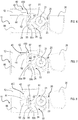
- Figure 1 illustrates an embodiment of a bicycle control device according to the invention, globally indicated with reference numeral 10.
- the control device 10 comprises a body 11, provided with an element 12 for fixing the control device 10 to a bicycle, and a cover 13, coupled with the body 11 through any fixing means, in the example of Figure 1 a screw 14.
- a screw 14 it is possible to provide for a irremovably fixed cover or for a device without a cover.
- control device 10 is preferably mounted at a handgrip I of the bicycle handlebars M through any mounting means, in the illustrated example a strap 15.
- the control device 10 can also be of the bar-end type.
- the control can, alternatively, be fixed in other positions on the bicycle frame, for example at a bottle holder.
- the strap 15 comprises an open loop portion 16 and an elongated portion 18, extending downwards from the open loop portion 16, on which at least one control device 10 is fixed. In mounted position on the strap 15, each control device 10 extends parallel to a longitudinal axis X of the handlebars M.
- control device 10 is fixed to the strap 15 by means of a screw 19 that passes through a hole 12a (shown in Figure 3 ) formed in the fixing element 12 of the body 11.
- the open loop portion 16 is configured to be slid onto the handlebars M, or alternatively onto a different portion of the bicycle frame, and then fixed through known fixing means, in the illustrated example a screw 17 for locking ends 16a, 16b of the loop facing each other.
- the illustrated control device 10 comprises at least one manual actuation member, herein a lever 20, which is supported by the body 11, movable between a rest position and an operating position.
- the manual actuation member can be of the button type.
- control device 10 mounted on the left can be substantially to the mirror image of the control device 10 mounted on the right.
- a control device 10 can be actuated by one of the cyclist's fingers, for example by exerting a pressure onto the manual actuation member 20, while the other control device 10 can be actuated by another of the cyclist's fingers, for example by exerting a traction onto the manual actuation member 20.
- one control device 10 can control the upward gearshifting of a rear derailleur of the bicycle, while another control device 10 can control the downward gearshifting of the rear derailleur.
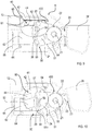
- the lever 20 is pivoted on the body 11 of the control device 10 through a pivot pin 21, fixed to the body 11.
- a return spring 25 is operatively interposed between the lever 20 and the body 11 at the pivot pin 21 to keep the lever 20 pushed towards the rest position.
- the lever 20 comprises a central body 22 for being pivoted to the pin 21, a driving arm 23 and a driven arm 24, which extend from the central body 22, preferably at diametrically opposite positions of the central body 22.
- the driving arm 23 extends from the central body 22 outside of the body 11, while the driven arm 24 extends from the central body 22 within the body 11.
- a hole 22a is also formed for receiving the screw 14 for fixing the cover 13 onto the body 11.
- a lever cover 26 is also mounted, configured so as to facilitate the actuation of the lever 20 by a cyclist.
- the lever cover 26 has, preferably at a rear face 26a thereof, a preferably horizontal slot 27, suitable for receiving a screw 28 for fixing the lever cover 26 on the lever 20.
- the slot 27 advantageously allows the mounting position of the lever cover 26 on the lever 20 to be adjusted along a longitudinal axis of the lever 20, so as to adapt the lever 20 to the size of the cyclist's hand.
- the position of the lever cover 26 is adjustable between a retracted position or position of minimum distance from the body 11, shown in Figure 4a , wherein the screw 28 abuts against an end 27a of the slot 27, and an extended position or position of maximum distance from the body 11, shown in Figure 4b , wherein the screw 28 abuts against the other end 27b of the slot 27.
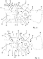
- a clicking mechanism 400 is also housed, which comprises a magnetic clicking switch 40.
- the magnetic clicking switch 40 comprises a first element 42 and a second element 44.
- the first element is fixed onto the body 11 of the control device 10, while the second element 44 is movable with respect to the first element 42.
- the lever 20 actuates the second element 44, displacing it with respect to the first element 42, when it issues the command to the bicycle equipment.
- the first element 42 can be fixed to the cover 13 for closing the body 11.
- first element 42 and the second element 44 of the magnetic clicking switch 40 cooperate so that, when the cyclist actuates the lever 20 to issue the command, the second element 44 moves, with respect to the first element 42, between a rest position, or idle position, of the clicking mechanism 400, and an operating position, or actuation position, of the clicking mechanism 400.
- the second element 44 contacts the first element and, in the operating position, the second element 44 is spaced apart from the first element 42.
- the reverse is also possible.
- the first element 42 of the magnetic clicking switch 40 is an element made of a metal that can be attracted by a magnet, typically iron, but also other types of metal, for example nickel, cobalt, chromium and alloys and compounds of these metals, while the second element 44 of the magnetic clicking switch 40 is a magnet.
- the first element 42 of the magnetic clicking switch 40 is a magnet
- the second element 44 of the magnetic switch is an element made of a metal capable of being attracted by a magnet, typically iron, but also other types of metal, for example nickel, cobalt, chromium and alloys and compounds of these metals.
- first element 42 and the second element 44 of the magnetic clicking switch 40 are two magnets having opposite poles facing each other.
- the clicking mechanism 400 further comprises a snapping device 50 suitable for cooperating with the lever 20 to actuate the clicking mechanism 400.
- the snapping device 50 comprises a snapping element 51 for supporting the second element 44 of the magnetic clicking switch 40.
- the second element 44 of the magnetic clicking switch 40 is fixed, for example screwed or welded, to a support body 52 made as one piece with the snapping element 51.
- the support body 52 of the second element 44 of the magnetic clicking switch 40 can be a separate component, for example a magnet-holding arm, which is fixed, for example screwed or welded, onto the snapping element 51 of the snapping device 50.
- the snapping element 51 preferably plate-like, is hinged to the pivot pin 21 of the lever 20, right below the lever 20, and has a slot 55 for slidably housing the first pin 29 of the lever 20.
- the slot 55 is formed at an edge portion of the snapping element 51 opposite to that where the snapping element 51 is pivoted onto the pin 21.
- the snapping device 50 further comprises a spring 56 having an end associated with the first pin 29 of the lever 20, and the other end associated with a second pin 57 fitted onto the snapping element 51.
- the second pin 57 extends from an upper surface of the snapping element 51 at the edge portion of the snapping element 51 wherein the slot 55 is formed, a suitable distance from the slot 55.
- the first element 42 and the second element 44 of the magnetic clicking switch 40 are kept in contact by the magnetic attraction force, and hold the snapping element 51 of the snapping device 50 in position. Furthermore, the first pin 29 of the lever 20 abuts against a first end 55a (the one at the top, labelled in Figure 7 ) of the slot 55.
- the snapping element 51 stays still, held in position by the magnetic attraction force between the first element 42 and the second element 44 of the magnetic clicking switch 40.
- the spring 56 connected between the first pin 29 of the lever 20 and the second pin 57 of the snapping element 51 stretches, and is loaded by the movement of the first pin 29 within the slot 55.
- the released snapping element 51 is therefore pulled back by the spring 56, with consequent sudden contact of the first pin 29 against the first end 55a of the slot 55 and generation of the tactile and acoustic feeling for the cyclist.
- Such an operating condition of the clicking mechanism 400 is shown in Figure 8 .
- the elastic characteristics of the spring 56 are such that the moving of the second element 42 away from the first element 44 of the magnetic switch 40 takes place before the first pin 29 of the lever 20 abuts against the second end 55b of the slot 55.
- the clicking mechanism 400 is, however, configured so as to operate also in case of changes of such elastic characteristics of the spring 56, typically due to wear.
- the first pin 29 would abut against the second end 55b of the slot 55, pulling the snapping element 51 therewith, progressively as the lever 20 is actuated, with consequent moving of the second element 44 away from the first element 42 of the magnetic switch 40.
- the correct operation of the clicking mechanism 400 is not influenced by malfunction or yielding of the spring 56.
- the return into the rest condition is preferably facilitated by the presence of the return spring 25 (see for example Figure 3 ).
- the return spring 25 could be omitted, in which case the magnetic attraction force of the magnetic clicking switch 40 will be such as to bring the second element 44 back into contact with the first element 42.
- control device 10 further comprises a control switch 60 configured to detect the actuation of the lever 20 by the cyclist and to generate a control signal of the bicycle component to be controlled with the control device 10.
- control switch 60 comprises a magnetic sensor 61 suitable for detecting the movement of the second element 44 of the magnetic clicking switch 40 with respect to the first element 42, and for generating a signal for issuing a command or control signal s 1 .
- the magnetic sensor 61 is in communication, in a wired or wireless manner, with an electronic communication unit 62, which receives the control signal s 1 generated by the sensor 61, processes it and transmits it to the bicycle component to be controlled.
- the signal is transmitted in a wireless manner, and in this case the electronic communication unit 62 is provided with a wireless transmitter 63.
- the magnetic sensor 61 can be connected directly, by an electric wire or wireless, to the bicycle equipment or component to be controlled.
- any switch suitable for the purpose for example an electric switch, preferably of the membrane type, connected in a wired or wireless manner to electrical or electro-mechanical bicycle equipment, or a control mechanism of the traction cable type, for example a Bowden cable, in the case of mechanical and/or pneumatic bicycle equipment.
- the magnetic sensor 61 and the electronic communication unit 62 are preferably integrated on a printed circuit board 65, which is mounted on the body 11 of the control device 10, for example through screws 64.
- the printed circuit board 65 is protected by a lid 66, for example visible in Figures 3 and 5 , which is fixed, preferably glued or ultrasound welded, onto the body 11 of the control device 10.
- the lid 66 is preferably made of fiberglass or plastic materials.
- two mutually separate seats are defined, namely a first seat 32, arranged above the lid 66, and a second seat 34, arranged below the lid 66.
- the first seat 32 is defined by the lid 66 and by the cover 13, while the second seat 34 is defined by the body 11 and by the lid 66.
- the non-electronic components- i.e. the mechanical and magnetic ones - of the control device 10 are housed, namely the magnetic clicking switch 40, the snapping device 50, and the driven arm 24 of the lever 20.
- the electronic components of the control device 10 are housed, namely the electronic communication unit 62, and the control switch 60.
- the second seat 34 consists of a sealed chamber, so that the electronic components are protected against dust and water, preferably providing an IP67 or IP69K degree of protection.
- the magnetic sensor 61 is so mounted on the printed circuit board 65 as to face the second element 44 of the magnetic clicking switch 40 when the lever 20 is in rest position, and distant or uncovered from the second magnetic element 44, when the lever 20 is fully actuated, with a consequent generation of the command.
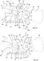
- the first element 42 of the magnetic clicking switch 40 is elongated, and the second element 44 of the magnetic clicking switch 40 is C-shaped, so as to form, with the first elongated element 42, a preferential magnetic circuit indicated by the dashed circle in Figures 9 and 10 .
- the first elongated element 42 is made of a ferromagnetic material and the second C-shaped element 44 is a magnet.
- the clicking mechanism 400 When the clicking mechanism 400 is inactive, i.e. when the first element 42 and the second element 44 of the magnetic clicking switch 40 are in contact with each other ( Figure 9 ), the preferential magnetic circuit is closed, with the magnetic field lines mainly conveyed internally thereof. In this operating condition, the magnetic field detected by the magnetic sensor 61 is less than a predetermined threshold value.
- the preferential magnetic circuit opens, and the magnetic field lines close partially also in air ( Figure 10 ).
- the magnetic sensor 61 detects the change in magnetic field, and generates the control signal s 1 , which is transmitted, directly or through the electronic communication unit 62, to the component or equipment of the bicycle to be controlled.
- the transmission of the control signal s 1 can also take place with a predetermined time delay with respect to the detection by the magnetic sensor 61. This, advantageously, allows the electronic communication unit 62 to abort the generation and transmission of the command, for example if the cyclist has actuated the lever 20 inadvertently or by mistake, and then releases it immediately.
- the magnetic sensor 61 can be so mounted on the printed circuit board 65 as to be such a distance from the magnetic clicking switch 40 as not to detect the magnetic field generated thereby when the lever 20 is in the rest position.
- the second element 44 of the magnetic clicking switch 40 moves away from the first element 42 of the magnetic clicking switch 40, the second element 44 approaches the magnetic sensor 61.
- the magnetic sensor 61 detects the presence of the magnetic field and generates, in real time or with a predetermined delay, a control signal, which is transmitted, directly or through the electronic communication unit 62, to the bicycle component to be controlled.
- Figures 12 and 13 show a second embodiment of a magnetic control switch, generally indicated with reference numeral 610, configured to detect the actuation of the lever 20 by the cyclist, and generate a corresponding control signal.
- such a magnetic control switch 610 comprises a magnetic sensor 611 suitable for detecting the movement of the second element 44 of the magnetic clicking switch 40 with respect to the first element 42, and for generating a corresponding control signal s 1 .
- the magnetic sensor 611 is in communication, in a cabled or wireless manner, with the electronic communication unit 62, which receives the control signal s 1 generated by the magnetic sensor 611, processes it and transmits it, through the wireless transmitter 63, to the bicycle component to be controlled.
- the magnetic sensor 611 can be connected directly, by electric wire or wireless, to the component of the bicycle to be controlled.
- the magnetic sensor 611 is sensitive to only one of the two poles (north pole or south pole) of the second element 44 of the magnetic clicking switch 40.
- the magnetic sensor 611 is so mounted on the printed circuit board 65, as to result, in the rest position of the lever 20, to be facing a pole, for example the north pole, of the second element 44 of the magnetic clicking switch 40 to which it is not sensitive.
- the magnetic sensor 611 When the magnetic clicking switch 40 is actuated, and the second element 44 moves away from the first element 42, the magnetic sensor 611 is exposed to the pole of the second element 44 of the magnetic clicking switch 40, for example the south pole, to which it is sensitive, and generates, in real time or after a predetermined delay, the control signal s 1 , which is transmitted, directly or through the electronic communication unit 62, to the bicycle component to be controlled.
- the first element 42 of the magnetic clicking switch 40 it is possible for the first element 42 of the magnetic clicking switch 40 to be a magnet, in which case the second element 42 of the magnetic clicking switch 40 will be sensitive to only one of the two poles (north pole or south pole) of the first element 42, and will be moved by the lever 20.
- Figures 11 , 14 and 15 illustrate a third embodiment of a magnetic control switch, configured to detect the actuation of the lever 20 by the cyclist, and to generate a corresponding control signal s 2 .
- Such a magnetic control switch differs from the magnetic command switches 60, 610 previously described in the different way of detecting the actuation of the lever 20.
- the magnetic control switch 620 comprises a third element, preferably a magnet 622 mounted on the snapping element 51 of the clicking device 50 of the clicking mechanism 400, and a fourth element, preferably a magnetic sensor 621 mounted on the printed circuit board 65 close to the snapping element 51.
- the magnet 622 can be mounted on the printed circuit board 65 close to the snapping element 51, and the magnetic sensor 621 on the snapping element 51.
- the magnetic control switch 620 turns out to be independent of the magnetic clicking switch 40.
- the magnetic sensor 621 is in communication, in a wired or wireless manner, with the electronic communication unit 62, which receives the control signal s 2 generated by the sensor 621, processes it and transmits it, through the wireless transmitter 63, to the bicycle component to be controlled.
- the magnetic sensor 621 can be connected directly, by electric wire or wireless, to the bicycle component to be controlled.
- the magnetic sensor 621 and the magnet 622 are arranged such a distance apart that the magnetic sensor 621 does not detect the magnetic field generated by the magnet 622.
- the magnet 622 Following the actuation of the lever 20, and in particular following the rotation of the snapping element 51 about the pin 21, due to the elastic force exerted by the spring 56, the magnet 622 approaches the magnetic sensor 621, which detects the magnetic field generated thereby.
- the magnetic sensor 621 thus generates, in real time or after a predetermined delay, the control signal s 2 , which is transmitted, directly or through the electronic communication unit 62, to the bicycle component to be commanded.
- the snapping device 50 is, more generally, part of the control device 10, being suitable not only to cooperate with the lever 20 to actuate the clicking mechanism 400, but also to cooperate with the lever 20 to issue the command to the bicycle equipment through the magnetic control switch 60, 610, 620.
- the snapping device 50 could be absent, the second element 44 of the magnetic clicking switch 40 of the clicking mechanism 400 and/or one of the elements of the magnetic control switch 60, 610, 620 being directly associated with the lever 20 so that the lever 20 directly controls the magnetic control switch 60, 610, 620 and/or the magnetic clicking switch 40 of the clicking mechanism 400.
- the tactile and/or acoustic feeling will be provided by the moving away from each other of, and return into contact of, the elements 42, 44 of the magnetic clicking switch 40 of the clicking mechanism 400.
- the control device 10 comprises an auxiliary magnetic switch 630, unrelated with the linkage of the lever 20.
- the auxiliary magnetic switch 630 comprises an auxiliary magnetic sensor 631 and an auxiliary magnet 632.
- the auxiliary magnetic sensor 631 is suitable for detecting the presence of the auxiliary magnet 632 and for generating a control signal s 3 (see Figure 11 ), which is transmitted, directly or through the electronic communication unit 62, to the bicycle component to be controlled.
- the auxiliary magnetic sensor 631 is mounted on the printed circuit board 65, preferably at a peripheral portion of the body 11 of the control device 10, while the auxiliary magnet 632 is mounted on the cover 13 and is movable with respect thereto, according to a button-type movement, between a position extracted from the cover 13, wherein it is sufficiently spaced from the auxiliary magnetic sensor 631 so that the auxiliary magnetic sensor 631 does not detect its presence, and a position partially inserted into the cover 13, wherein the auxiliary magnetic sensor 631 detects the magnetic field generated thereby and generates the command signal s 3 , which is transmitted, directly or through the electronic communication unit 62, to the component of the bicycle to be commanded.
- an external auxiliary magnet 632 can be provided for, to be laid in a suitable seat 634 (shown in Figure 17 ) formed at the body 11 or at the cover 13 of the control device 10, or simply to be brought near the control device 10 when one wishes to generate a further command signal for the equipment or component of the bicycle commanded by the control device 10 or for a different component of the bicycle.
- it can be a mode button associated with the configuration and/or with the pairing (association of wireless devices in a network), that in principle is not to be actuated during normal use of the bicycle.
- such light signaling means consist of an LED ( Light Emitting Diode ) 80 in electrical communication with the magnetic sensor 61, 611, 621, 631 of the magnetic control switch 60, 610, 620 or of the auxiliary magnetic switch 630.
- the LED is in electrical communication with the electronic communication unit 62, which manages the switching on thereof as a function of a status or an operating condition of the control device 10 and/or of the bicycle equipment.
- the LED switches on when the gearshifting mechanism triggers, i.e. when the rear derailleur displaces the chain onto a toothed wheel having a larger diameter.
- control device 10 further comprises power supply means, in the illustrated embodiment a battery 70, preferably of the button type.
- a battery 70 preferably of the button type.
- the battery 70 is in communication with the electronic communication unit 62, through which it supplies power to the magnetic control switch 60, 610, 620, the auxiliary magnetic switch 630 and the LED 80, where provided for.
- the electronic communication unit 62 can be omitted, and in that case the battery 70 directly supplies power to the aforementioned electronic components.
- the battery 70 is housed in a preferably circular seat 72, so formed in a bottom surface 11 a of the body 11 as to leave a portion of the printed circuit board 65 uncovered, in which contacts 74 for the battery 70 are present.
- a groove is also formed for housing a sealing element 76, for example an O-ring.
- the seat 72 is furthermore closed by a cap 78 provided with tabs 71, which cooperate with matching elements (not shown) formed in the body 11 of the control device 10, to keep the cap 78 in locked position onto the seat 72.
Landscapes
- Engineering & Computer Science (AREA)
- Mechanical Engineering (AREA)
- Chemical & Material Sciences (AREA)
- Combustion & Propulsion (AREA)
- Transportation (AREA)
- Mechanical Control Devices (AREA)
- Rotary Switch, Piano Key Switch, And Lever Switch (AREA)
- Push-Button Switches (AREA)
- Switches With Compound Operations (AREA)
- Automatic Cycles, And Cycles In General (AREA)
- Axle Suspensions And Sidecars For Cycles (AREA)
Applications Claiming Priority (1)
| Application Number | Priority Date | Filing Date | Title |
|---|---|---|---|
| IT102016000081324A IT201600081324A1 (it) | 2016-08-02 | 2016-08-02 | Dispositivo di comando per bicicletta |
Publications (1)
| Publication Number | Publication Date |
|---|---|
| EP3279074A1 true EP3279074A1 (fr) | 2018-02-07 |
Family
ID=57610278
Family Applications (1)
| Application Number | Title | Priority Date | Filing Date |
|---|---|---|---|
| EP17180081.6A Withdrawn EP3279074A1 (fr) | 2016-08-02 | 2017-07-06 | Dispositif de commande d'une bicyclette |
Country Status (6)
| Country | Link |
|---|---|
| US (1) | US10676156B2 (fr) |
| EP (1) | EP3279074A1 (fr) |
| JP (1) | JP7032074B2 (fr) |
| CN (1) | CN107672727B (fr) |
| IT (1) | IT201600081324A1 (fr) |
| TW (1) | TWI713762B (fr) |
Cited By (5)
| Publication number | Priority date | Publication date | Assignee | Title |
|---|---|---|---|---|
| IT202100024800A1 (it) * | 2021-09-28 | 2023-03-28 | Campagnolo Srl | Equipaggiamento di bicicletta elettronico |
| US11884355B2 (en) | 2021-07-27 | 2024-01-30 | Campagnolo S.R.L. | Manual control device for a bicycle |
| US11919594B2 (en) | 2021-09-28 | 2024-03-05 | Campagnolo S.R.L. | Bicycle equipment provided with an electric power supply unit |
| US11952074B2 (en) | 2021-07-27 | 2024-04-09 | Campagnolo S.R.L. | Manual control device for a bicycle |
| US11958564B2 (en) | 2021-07-27 | 2024-04-16 | Campagnolo S.R.L. | Manual control device for a bicycle |
Families Citing this family (4)
| Publication number | Priority date | Publication date | Assignee | Title |
|---|---|---|---|---|
| DE202019102653U1 (de) | 2019-05-10 | 2019-07-03 | Sram Deutschland Gmbh | Fahrradbedienvorrichtung |
| US11472510B2 (en) * | 2019-11-13 | 2022-10-18 | Shimano Inc. | Electric device for human-powered vehicle |
| US11827307B2 (en) * | 2021-05-05 | 2023-11-28 | Shimano Inc. | Operating device for human-powered vehicle |
| CN113799900B (zh) * | 2021-10-25 | 2022-11-22 | 梅州市明眸电子科技有限公司 | 车辆刹车握把用刹车警示触发装置 |
Citations (8)
| Publication number | Priority date | Publication date | Assignee | Title |
|---|---|---|---|---|
| US20050099277A1 (en) * | 2003-11-06 | 2005-05-12 | Richard Hsu | Bike braking warning control |
| EP1964762A2 (fr) | 2007-03-01 | 2008-09-03 | CAMPAGNOLO S.r.l. | Dispositif de contrôle pour bicyclette et bicyclette l'utilisant |
| US20100186538A1 (en) * | 2009-01-26 | 2010-07-29 | Shimano Inc. | Bicycle control device |
| US20110035039A1 (en) * | 2008-06-30 | 2011-02-10 | Bombardier Recreational Products Inc. | Lever position sensor |
| US20120255390A1 (en) * | 2011-04-07 | 2012-10-11 | Warren Vincent M | Collapsible control lever |
| US20140144281A1 (en) * | 2012-11-28 | 2014-05-29 | Shimano Inc. | Bicycle electric control device with adjustable switch unit |
| US20140208888A1 (en) | 2013-01-31 | 2014-07-31 | Shimano Inc. | Bicycle operating device |
| EP2856274A1 (fr) * | 2012-05-25 | 2015-04-08 | Stefan Koller | Dispositif de changement de vitesse |
Family Cites Families (48)
| Publication number | Priority date | Publication date | Assignee | Title |
|---|---|---|---|---|
| JPH0688025U (ja) * | 1993-06-01 | 1994-12-22 | 日立精工株式会社 | スイッチ |
| JP2000085656A (ja) * | 1998-09-08 | 2000-03-28 | Bridgestone Cycle Co | 自転車用表示灯 |
| US6341538B1 (en) * | 1999-05-27 | 2002-01-29 | Shimano (Singapore) Private, Ltd. | Cable connecting apparatus for a bicycle component |
| IT1320285B1 (it) * | 2000-03-29 | 2003-11-26 | Campagnolo Srl | Procedimento per il controllo del cambio di velocita' in un ciclo,relativo sistema e relativi componenti. |
| US6590763B2 (en) * | 2001-02-13 | 2003-07-08 | Shimano Inc. | Weatherproof switch assembly |
| ITTO20010555A1 (it) * | 2001-06-08 | 2002-12-08 | Campagnolo Srl | Dispositivo di comando elettrico per un deragliatore motorizzato per biciclette. |
| JP3860737B2 (ja) * | 2001-10-22 | 2006-12-20 | 株式会社シマノ | 自転車用リアディレーラ |
| US6698307B2 (en) * | 2001-10-23 | 2004-03-02 | Sram Corporation | Electronic shifter for a bicycle |
| US6734376B2 (en) * | 2002-06-19 | 2004-05-11 | Shimano Inc. | Electrical switch device for bicycle |
| JP3101270U (ja) * | 2003-10-29 | 2004-06-10 | 志安 許 | 自転車用ブレーキランプの制御装置 |
| US7290458B2 (en) * | 2004-02-24 | 2007-11-06 | Shimano, Inc. | Bicycle derailleur with a motor disposed within a linkage mechanism |
| JP4412355B2 (ja) * | 2007-06-08 | 2010-02-10 | 株式会社デンソー | シフトレンジ切替装置 |
| US7761212B2 (en) * | 2008-03-24 | 2010-07-20 | Shimano Inc. | Wireless communication apparatus |
| WO2009136801A1 (fr) * | 2008-05-09 | 2009-11-12 | Cranklock Limited | Cadenas de manivelle de bicyclette |
| US7900946B2 (en) * | 2009-03-31 | 2011-03-08 | Shimano Inc. | Bicycle shifting control apparatus |
| US8655561B2 (en) | 2010-06-23 | 2014-02-18 | Shimano Inc. | Bicycle control system having a value generating unit |
| US8721495B2 (en) * | 2011-06-17 | 2014-05-13 | Shimano Inc. | Rear derailleur and gear shift system |
| EP2562070B1 (fr) * | 2011-08-26 | 2015-02-18 | Campagnolo S.r.l. | Dispositif d'actionnement d'un changeur de vitesse positionné à l'extrémite de guidon de bicyclette |
| US8955395B2 (en) * | 2012-05-24 | 2015-02-17 | Ronald Greggory Bjork | Magneto cyclist power sensor |
| US9056651B2 (en) | 2012-08-27 | 2015-06-16 | Shimano Inc. | Bicycle control device |
| US8909424B2 (en) * | 2012-10-11 | 2014-12-09 | Sram, Llc | Electronic shifting systems and methods |
| US9802669B2 (en) * | 2012-10-11 | 2017-10-31 | Sram, Llc | Electronic shifting systems and methods |
| US9145183B2 (en) | 2012-11-16 | 2015-09-29 | Shimano Inc. | Adjustable bicycle electric control device |
| US9594393B2 (en) | 2013-01-31 | 2017-03-14 | Shimano Inc. | Bicycle operating device |
| US8955863B2 (en) | 2013-01-31 | 2015-02-17 | Shimano Inc. | Bicycle operating device |
| US9836076B2 (en) | 2013-01-31 | 2017-12-05 | Shimano Inc. | Bicycle operating device |
| DE202013002492U1 (de) | 2013-03-15 | 2014-06-17 | Rti Sports Vertrieb Von Sportartikeln Gmbh | Fahrradgriff-System |
| DE202013002490U1 (de) | 2013-03-15 | 2014-06-17 | Rti Sports Vertrieb Von Sportartikeln Gmbh | Fahrradgriffsystem |
| DE202013002491U1 (de) | 2013-03-15 | 2014-06-17 | Rti Sports Vertrieb Von Sportartikeln Gmbh | Fahrradgriff-System |
| US9593764B2 (en) * | 2013-04-05 | 2017-03-14 | Shimano Inc. | Bicycle component operating apparatus |
| US8958962B2 (en) | 2013-04-05 | 2015-02-17 | Shimano Inc. | Electric shift operating device |
| US9157523B2 (en) | 2013-05-27 | 2015-10-13 | Shimano Inc. | Bicycle component actuation apparatus |
| JP2014231331A (ja) | 2013-05-30 | 2014-12-11 | 株式会社シマノ | 操作装置 |
| US20140371953A1 (en) | 2013-06-18 | 2014-12-18 | Craig M. Miller | Bicycle system utilizing wireless technology and method of using the same |
| JP2015027861A (ja) | 2013-07-05 | 2015-02-12 | 株式会社シマノ | 自転車制御システム |
| ITMI20131912A1 (it) * | 2013-11-19 | 2015-05-20 | Campagnolo Srl | Dispositivo e sistema di comando di un sistema elettronico di bicicletta e sistema elettronico di bicicletta impiegante gli stessi |
| EP2908097B1 (fr) * | 2014-02-13 | 2016-11-16 | iwis antriebssysteme GmbH & Co. KG | Capteur à réluctance pour chaîne et procédé de mesure d'étirement de chaîne |
| TWI586576B (zh) | 2014-07-31 | 2017-06-11 | 禧瑪諾(新)私人有限公司 | 操作裝置 |
| TWI664110B (zh) * | 2014-10-03 | 2019-07-01 | 義大利商坎帕克諾羅公司 | 自行車控制裝置 |
| DE202014105749U1 (de) | 2014-11-27 | 2015-01-09 | iCradle GmbH | Daumenschalter zur Befestigung an einem Fahrradlenker und über einen derartigen Daumenschalter bedienbares Steuersystem für ein Fahrrad |
| US10029754B2 (en) * | 2015-03-06 | 2018-07-24 | Shimano Inc. | Bicycle electrical system |
| US9764796B2 (en) * | 2015-03-19 | 2017-09-19 | GM Global Technology Operations LLC | Electric bike optical shift detection and control |
| US9919616B2 (en) * | 2015-04-21 | 2018-03-20 | Shimano Inc. | Control system for bicycle |
| DE202015103457U1 (de) | 2015-07-01 | 2015-10-08 | Shimano Inc. | Fahrradkomponente und Kommunikationssystem für eine Fahrradkomponente |
| IT201600131281A1 (it) * | 2016-12-27 | 2018-06-27 | Campagnolo Srl | Rilevatore per bicicletta |
| IT201600131314A1 (it) * | 2016-12-27 | 2018-06-27 | Campagnolo Srl | Deragliatore elettronico wireless di bicicletta |
| IT201700038213A1 (it) * | 2017-04-06 | 2018-10-06 | Campagnolo Srl | Dispositivo manuale di comando per bicicletta e sistema elettronico di bicicletta che lo comprende |
| IT201800005937A1 (it) * | 2018-06-01 | 2019-12-01 | Dispositivo di comando per bicicletta |
-
2016
- 2016-08-02 IT IT102016000081324A patent/IT201600081324A1/it unknown
-
2017
- 2017-07-06 EP EP17180081.6A patent/EP3279074A1/fr not_active Withdrawn
- 2017-07-12 TW TW106123301A patent/TWI713762B/zh active
- 2017-07-31 US US15/664,241 patent/US10676156B2/en active Active
- 2017-07-31 JP JP2017147684A patent/JP7032074B2/ja active Active
- 2017-08-01 CN CN201710646066.1A patent/CN107672727B/zh active Active
Patent Citations (8)
| Publication number | Priority date | Publication date | Assignee | Title |
|---|---|---|---|---|
| US20050099277A1 (en) * | 2003-11-06 | 2005-05-12 | Richard Hsu | Bike braking warning control |
| EP1964762A2 (fr) | 2007-03-01 | 2008-09-03 | CAMPAGNOLO S.r.l. | Dispositif de contrôle pour bicyclette et bicyclette l'utilisant |
| US20110035039A1 (en) * | 2008-06-30 | 2011-02-10 | Bombardier Recreational Products Inc. | Lever position sensor |
| US20100186538A1 (en) * | 2009-01-26 | 2010-07-29 | Shimano Inc. | Bicycle control device |
| US20120255390A1 (en) * | 2011-04-07 | 2012-10-11 | Warren Vincent M | Collapsible control lever |
| EP2856274A1 (fr) * | 2012-05-25 | 2015-04-08 | Stefan Koller | Dispositif de changement de vitesse |
| US20140144281A1 (en) * | 2012-11-28 | 2014-05-29 | Shimano Inc. | Bicycle electric control device with adjustable switch unit |
| US20140208888A1 (en) | 2013-01-31 | 2014-07-31 | Shimano Inc. | Bicycle operating device |
Cited By (6)
| Publication number | Priority date | Publication date | Assignee | Title |
|---|---|---|---|---|
| US11884355B2 (en) | 2021-07-27 | 2024-01-30 | Campagnolo S.R.L. | Manual control device for a bicycle |
| US11952074B2 (en) | 2021-07-27 | 2024-04-09 | Campagnolo S.R.L. | Manual control device for a bicycle |
| US11958564B2 (en) | 2021-07-27 | 2024-04-16 | Campagnolo S.R.L. | Manual control device for a bicycle |
| IT202100024800A1 (it) * | 2021-09-28 | 2023-03-28 | Campagnolo Srl | Equipaggiamento di bicicletta elettronico |
| EP4156862A1 (fr) * | 2021-09-28 | 2023-03-29 | Campagnolo S.r.l. | Equipement electronique de bicyclette |
| US11919594B2 (en) | 2021-09-28 | 2024-03-05 | Campagnolo S.R.L. | Bicycle equipment provided with an electric power supply unit |
Also Published As
| Publication number | Publication date |
|---|---|
| JP2018039496A (ja) | 2018-03-15 |
| CN107672727B (zh) | 2020-10-23 |
| IT201600081324A1 (it) | 2018-02-02 |
| TW201805201A (zh) | 2018-02-16 |
| US10676156B2 (en) | 2020-06-09 |
| TWI713762B (zh) | 2020-12-21 |
| US20180037299A1 (en) | 2018-02-08 |
| JP7032074B2 (ja) | 2022-03-08 |
| CN107672727A (zh) | 2018-02-09 |
Similar Documents
| Publication | Publication Date | Title |
|---|---|---|
| US10676156B2 (en) | Bicycle control device | |
| US11383793B2 (en) | Control device for wirelessly controlling at least one component of a bicycle | |
| US8035046B2 (en) | Control device for a bicycle and bicycle comprising same | |
| CN107416110B (zh) | 操作装置 | |
| US20140058578A1 (en) | Bicycle control device | |
| US9090304B2 (en) | Bicycle control device | |
| US10730580B2 (en) | Bicycle control device | |
| US8272292B2 (en) | Control device for a bicycle and bicycle comprising same | |
| EP0067692B1 (fr) | Dispositif de commande pour un dérailleur à deux vitesses | |
| TWI374834B (en) | Electrically operated derailleur that re-engages a disengaged derailleur force overload clutch | |
| US10672240B2 (en) | Operating device for operating an electrical bicycle component | |
| US20070000343A1 (en) | Electrical switch apparatus for a bicycle control device | |
| JP2018039496A5 (fr) | ||
| US20080210045A1 (en) | Control device for a bicycle and bicycle comprising same | |
| HK1118774A1 (en) | Sensor device | |
| EP1024238A3 (fr) | Dispositif pour la détection de la position d'un pêne de serrure | |
| CN111216838B (zh) | 车辆配件的控制方法 | |
| WO2009028131A1 (fr) | Réfrigérateur | |
| TWI781864B (zh) | 變速控制盒及自行車控制組件 | |
| CN113264147A (zh) | 一种自行车操作装置及自行车 | |
| PL341457A1 (en) | Triggering mechanism for an automatic circuit-breaker | |
| KR101043522B1 (ko) | 텀블러 스위치 유니트 | |
| TW200420470A (en) | Electrical operation device for bicycle |
Legal Events
| Date | Code | Title | Description |
|---|---|---|---|
| PUAI | Public reference made under article 153(3) epc to a published international application that has entered the european phase |
Free format text: ORIGINAL CODE: 0009012 |
|
| STAA | Information on the status of an ep patent application or granted ep patent |
Free format text: STATUS: THE APPLICATION HAS BEEN PUBLISHED |
|
| AK | Designated contracting states |
Kind code of ref document: A1 Designated state(s): AL AT BE BG CH CY CZ DE DK EE ES FI FR GB GR HR HU IE IS IT LI LT LU LV MC MK MT NL NO PL PT RO RS SE SI SK SM TR |
|
| AX | Request for extension of the european patent |
Extension state: BA ME |
|
| STAA | Information on the status of an ep patent application or granted ep patent |
Free format text: STATUS: REQUEST FOR EXAMINATION WAS MADE |
|
| 17P | Request for examination filed |
Effective date: 20180806 |
|
| RBV | Designated contracting states (corrected) |
Designated state(s): AL AT BE BG CH CY CZ DE DK EE ES FI FR GB GR HR HU IE IS IT LI LT LU LV MC MK MT NL NO PL PT RO RS SE SI SK SM TR |
|
| STAA | Information on the status of an ep patent application or granted ep patent |
Free format text: STATUS: EXAMINATION IS IN PROGRESS |
|
| 17Q | First examination report despatched |
Effective date: 20200623 |
|
| STAA | Information on the status of an ep patent application or granted ep patent |
Free format text: STATUS: EXAMINATION IS IN PROGRESS |
|
| STAA | Information on the status of an ep patent application or granted ep patent |
Free format text: STATUS: EXAMINATION IS IN PROGRESS |
|
| P01 | Opt-out of the competence of the unified patent court (upc) registered |
Effective date: 20230516 |
|
| STAA | Information on the status of an ep patent application or granted ep patent |
Free format text: STATUS: THE APPLICATION IS DEEMED TO BE WITHDRAWN |
|
| 18D | Application deemed to be withdrawn |
Effective date: 20231109 |