EP3279019A2 - Luftausströmer-verstellanordnung - Google Patents
Luftausströmer-verstellanordnung Download PDFInfo
- Publication number
- EP3279019A2 EP3279019A2 EP17179426.6A EP17179426A EP3279019A2 EP 3279019 A2 EP3279019 A2 EP 3279019A2 EP 17179426 A EP17179426 A EP 17179426A EP 3279019 A2 EP3279019 A2 EP 3279019A2
- Authority
- EP
- European Patent Office
- Prior art keywords
- sliding block
- valve flap
- guide
- valve
- block carrier
- Prior art date
- Legal status (The legal status is an assumption and is not a legal conclusion. Google has not performed a legal analysis and makes no representation as to the accuracy of the status listed.)
- Granted
Links
Images

Classifications
-
- B—PERFORMING OPERATIONS; TRANSPORTING
- B60—VEHICLES IN GENERAL
- B60H—ARRANGEMENTS OF HEATING, COOLING, VENTILATING OR OTHER AIR-TREATING DEVICES SPECIALLY ADAPTED FOR PASSENGER OR GOODS SPACES OF VEHICLES
- B60H1/00—Heating, cooling or ventilating devices
- B60H1/34—Nozzles; Air-diffusers
-
- B—PERFORMING OPERATIONS; TRANSPORTING
- B60—VEHICLES IN GENERAL
- B60H—ARRANGEMENTS OF HEATING, COOLING, VENTILATING OR OTHER AIR-TREATING DEVICES SPECIALLY ADAPTED FOR PASSENGER OR GOODS SPACES OF VEHICLES
- B60H1/00—Heating, cooling or ventilating devices
- B60H1/34—Nozzles; Air-diffusers
- B60H1/3414—Nozzles; Air-diffusers with means for adjusting the air stream direction
- B60H1/3421—Nozzles; Air-diffusers with means for adjusting the air stream direction using only pivoting shutters
-
- F—MECHANICAL ENGINEERING; LIGHTING; HEATING; WEAPONS; BLASTING
- F16—ENGINEERING ELEMENTS AND UNITS; GENERAL MEASURES FOR PRODUCING AND MAINTAINING EFFECTIVE FUNCTIONING OF MACHINES OR INSTALLATIONS; THERMAL INSULATION IN GENERAL
- F16H—GEARING
- F16H27/00—Step-by-step mechanisms without freewheel members, e.g. Geneva drives
- F16H27/04—Step-by-step mechanisms without freewheel members, e.g. Geneva drives for converting continuous rotation into a step-by-step rotary movement
- F16H27/06—Mechanisms with driving pins in driven slots, e.g. Geneva drives
-
- B—PERFORMING OPERATIONS; TRANSPORTING
- B60—VEHICLES IN GENERAL
- B60H—ARRANGEMENTS OF HEATING, COOLING, VENTILATING OR OTHER AIR-TREATING DEVICES SPECIALLY ADAPTED FOR PASSENGER OR GOODS SPACES OF VEHICLES
- B60H1/00—Heating, cooling or ventilating devices
- B60H1/34—Nozzles; Air-diffusers
- B60H2001/3471—Details of actuators
- B60H2001/3478—Details of actuators acting on additional damper doors
-
- F—MECHANICAL ENGINEERING; LIGHTING; HEATING; WEAPONS; BLASTING
- F16—ENGINEERING ELEMENTS AND UNITS; GENERAL MEASURES FOR PRODUCING AND MAINTAINING EFFECTIVE FUNCTIONING OF MACHINES OR INSTALLATIONS; THERMAL INSULATION IN GENERAL
- F16H—GEARING
- F16H27/00—Step-by-step mechanisms without freewheel members, e.g. Geneva drives
Definitions
- the invention relates to a Lucasausströmer adjustment for a motor vehicle.
- air vents are used for the air conditioning of the vehicle interior and are known in various designs.
- the air vents usually include an air vent housing in which adjustable louvers are arranged.
- the louvers are designed as valve flaps or vanes, wherein the direction of the air flow emerging from the air vent can be adjusted via the valve flaps of the volume flow and the guide vanes.
- the adjustment of the louvers is usually carried out with an adjustment, which acts on the louvers and can be manually operated by the vehicle occupant or electrically by an electric drive.
- an adjusting arrangement for an air vent is known, which is designed as a gear transmission.
- the adjusting arrangement has a drive gear driven by an electric drive, which is operatively connected in a first movement section with an output gear connected to guide vanes and in a second movement section with an output gear connected to valve flaps.
- the adjustment of the valve flaps and the vanes takes place via the rotation of the drive gear. In a middle position, neither of the two output gears is operatively connected to the drive gear.
- the first or the second movement section is traversed and thereby either the valve flaps or the guide vanes adjusted. If the teeth of the output gears are not in engagement with the teeth of the drive gear, the respective output gear is fixed in a rotationally blocking manner via a guide element formed on the end face of the drive gear, wherein the driven gears each have a counter guide element adjoining their end faces, which interacts in each case with the guide element.
- the object of the invention is therefore to provide a Lucasausströmer adjustment for a motor vehicle, which is simple and inexpensive to produce.
- the Heilausströmer adjustment arrangement has a driven by an electric drive drive unit which cooperates with at least one valve flap and at least one guide blade.
- the drive unit is composed of a valve flap link, a guide plate backdrop, a sliding block and a sliding block carrier, wherein the sliding block carrier has at least a first rotary motion section and a second rotary motion section.
- the length and position of the rotational movement sections to each other can be defined depending on the requirement.
- the Kulissensteinzi can be performed, for example disc-shaped and driven directly by an electric drive.
- the sliding block carrier can form the output gear of a gear transmission, a belt drive or a chain drive.
- the sliding block On the front side of the disk-shaped Kulissensteintos the sliding block is arranged eccentrically, wherein the sliding block may be a bolt which is attached via a screw, glued or welded connection to the sliding block carrier. Due to the eccentric arrangement of the sliding block on the sliding block carrier and the rotation of Kulissensteinmons the sliding block moves on a circular path and attacks, depending on which rotary motion section of the sliding block carrier is traversed, in the valve gate scenery or the Leitlamellen scenery.
- valve gate scenery and the Leitlamellen scenery are indirectly or directly connected to the valve flap or the Leitlamelle.
- the valve gate and the guide vanes backdrop each have a slot or a groove, which are aligned with their open ends to the circular path of the sliding block that moved on its orbit sliding block in the slot or in the groove of the valve gate backdrop or the Leitlamellen scenery can intervene.
- the engagement of the sliding block in the valve gate backdrop or in the Leitlamellen scenery is dependent on which rotary motion section of the sliding block carrier is traversed.
- the first rotary motion section of the sliding block engages in the valve gate backdrop and rotates the valve gate and the associated valve flap continuously between an open and closed position.
- the rotation of the Leitlamelle, while the second rotational movement portion of the sliding block carrier is traversed and the sliding block engages in the Leitlamellen scenery.
- Such a configuration of the adjustment can be made simple and inexpensive, since the individual components of the adjustment can be easily produced. In this case, the adjustment has no gears, which would have to be made consuming and costly.
- the first and the second rotary motion section do not overlap, so that either the valve flaps or the guide vanes are displaced when passing through the respective rotary motion sections.
- the air damper backdrop can be designed independently of the Leitlamellen scenery, whereby the production and design of the scenes is facilitated.
- the drive unit is designed as a transmission.
- the drive unit is, for example, a single-stage helical gear and has a drive gear and an output gear, wherein the drive gear is driven via a drive shaft by the electric drive and the output gear serves as a sliding block carrier.
- a commercially available electric motor as an electric drive can be used, wherein the relatively slow rotational speed of the valve flaps or the guide vanes can be adjusted via the selected gear ratio.
- valve gate backdrop and the Leitlamellen backdrop each have a slot into which the sliding block can engage.
- valve gate scenery and the Leitlamellen scenery could each have a groove into which the sliding block can engage.
- the slot or the groove can have any desired shape, whereby the rotation of the valve flaps or the guide vanes can be dynamically influenced.
- the sliding block support on a guide element which extends axially from an end face of the sliding block carrier and with the peripheral surface serves as a guide for the valve gate scenery and the Leitlamellen scenery with non-engaging sliding block.
- the valve flap backdrop and the Leitlamellen backdrop each have a counter-guide element which cooperates with the guide element. In this way, the valve flap or the guide plate can be rotationally blocked even when not intervening in the valve gate backdrop or guide plate backdrop sliding block.
- the axis of rotation of the valve flap is aligned parallel to the axis of rotation of the guide plate. This allows the drive unit can be performed easily and with few components, since the drive unit engages in a common plane on the valve gate and the guide vanes backdrop and no deflection of the force is needed in another plane.
- the axis of rotation of the valve flap is aligned perpendicular to the axis of rotation of the guide plate.
- the flapper is located upstream of the baffle, thereby leaving the vehicle occupant-visible design of the air vaporizer virtually unchanged during the various positions of the flapper and baffle.
- a plurality of vanes are advantageous, whereby the emerging from the air vent airflow can be better performed.
- the valve gate is non-rotatably connected to a valve flap and connected to other valve flaps via the valve flap connecting elements, so that all valve flaps are rotated together and synchronously by the rotation of the valve flap link.
- a guide plate is non-rotatably connected to the guide plate guide and via the guide plate connecting element with further guide plates, wherein all the guide plates are rotated together by the rotation of the guide plate guide.
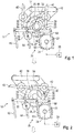
- FIG. 1 shows a schematic view of a Lucasausströmer adjustment assembly 10 with a drive unit 20, which is designed as a transmission.
- the drive unit 20 has a drive gear 24 which is rotatably connected to a driven by an electric drive shaft 22.
- the drive gear 24 meshes with an output gear 27 and drives the output gear 27.
- a sliding block 30 is arranged eccentrically, so that the output gear 27 serves as a sliding block carrier 26.
- the output gear 27 has a first rotary motion section 36, a second rotary motion section 38 and a central rotary motion section 37, wherein in the first rotary motion section 36 of the sliding block 30 in a valve gate 32, in the second rotary motion section 38 in a guide vanes backdrop 34 and in the central rotational movement section 37 engages neither in the valve gate 32 or in the guide plate 34.
- the valve gate 32 is connected to a valve flap 40 and via a valve flap connecting element 42 with a second valve flap 43, so that both valve flaps 40, 43 are rotated by the rotation of the valve flap scenes 32.
- the guide plate 34 is connected to a guide plate 64 and a guide plate connecting element 62 with three further guide plates 60, 66, 68, whereby the guide plates 60, 62, 66, 68 together and synchronously rotated by the rotation of the guide plate 34 become.
- valve gate 32 and the Leitlamellen scenery 34 each have a counter-guide element 33,35, which slides on a driven gear 27 formed on the guide element 23 when the sliding block 30 is not in the valve gate 32 or not in the Leitlamellen scenery 34 intervenes.
- the valve gate 32 is blocked against rotation when the sliding block 30 with the guide plate 34 is engaged. If the sliding block 30 engages in the valve gate 32, the counter-guide element 33 does not rest on the guide element 23, wherein the guide element 23 has a recess 29 so that the rotation of the valve gate 32 is not blocked by the guide element 23.
- FIG. 1 shows a position of the sliding block support 26 in the central rotary motion section 37, wherein the sliding block 30 engages neither in the valve gate 32 still in the guide plate 34.
- the counter-guide elements 33, 35 abut on the guide element 23, whereby the valve gate 32 and the Leitlamellen link 34 are fixed by the guide member 23 rotationally blocking and the valve flaps 40, 43 and the guide vanes 60, 64, 66, 68 are aligned in the direction of air flow.
- the direction of the air flow is shown in the figures as a contoured arrow.
- FIG. 2 engages the sliding block 30 in a slot formed on the valve gate 32 slot 48, wherein the valve flaps 40, 43 are shown in the transverse or closed position, which adjusts after the first rotary motion portion 36 of the sliding block carrier was traversed.
- the free flow cross-section of the flow reduces Luftausströmers, until the rotary motion section end of the air vent is completely closed.
- FIG. 3 shows the passage through the second rotary motion section 38 and the engagement of the sliding block 30 in the guide plate guide 34.
- the guide plate 34 has for this purpose a slot 50 in which the sliding block 30 slides and the guide plate 34 twisted. Due to the rotation of the guide vanes scenes, the guide vanes 60, 64, 66, 68 are rotated synchronously. In this way, the direction of the air flow can be adjusted, wherein intermediate positions in the second rotary motion section 38 can be adjusted via the electric drive.
Landscapes
- Engineering & Computer Science (AREA)
- Mechanical Engineering (AREA)
- Physics & Mathematics (AREA)
- Thermal Sciences (AREA)
- General Engineering & Computer Science (AREA)
- Mechanically-Actuated Valves (AREA)
- Air-Conditioning For Vehicles (AREA)
- Air-Flow Control Members (AREA)
Abstract
Description
- Die Erfindung betrifft eine Luftausströmer-Verstellanordnung für ein Kraftfahrzeug.
- Im Bereich der Kraftfahrzeugtechnik werden Luftausströmer für die Klimatisierung des KFZ-Innenraums eingesetzt und sind in unterschiedlichsten Ausführungen bekannt. Die Luftausströmer umfassen üblicherweise ein Luftausströmer-Gehäuse, in dem verstellbare Luftklappen angeordnet sind. Die Luftklappen sind dabei als Ventilklappen oder Leitlamellen ausgeführt, wobei über die Ventilklappen der Volumenstrom und über die Leitlamellen die Richtung des aus dem Luftausströmer austretenden Luftstroms einstellbar sind.
- Die Verstellung der Luftklappen erfolgt üblicherweise mit einer Verstellanordnung, die an den Luftklappen angreift und die manuell durch den Fahrzeuginsassen oder elektrisch durch einen elektrischen Antrieb betätigt werden kann. Aus der
EP I 520 738 - Problematisch an einer derartigen Luftausströmer-Verstellanordnung für ein Kraftfahrzeug ist, dass die Verstellanordnung aufgrund der komplexen Ausgestaltung des Antriebszahnrades und der beiden Abtriebszahnräder aufwendig und kostenintensiv herstellbar ist.
- Die Aufgabe der Erfindung ist es daher, eine Luftausströmer-Verstellanordnung für ein Kraftfahrzeug bereitzustellen, die einfach und kostengünstig herstellbar ist.
- Diese Aufgabe wird durch eine Luftausströmer-Verstellanordnung mit den Merkmalen des Hauptanspruchs gelöst.
- Die Luftausströmer-Verstellanordnung weist eine durch einen elektrischen Antrieb angetriebene Antriebseinheit auf, die mit mindestens einer Ventilklappe und mindestens einer Leitlamelle zusammenwirkt.
- Erfindungsgemäß setzt sich die Antriebseinheit aus einer Ventilklappen-Kulisse, einer Leitlamellen-Kulisse, einem Kulissenstein und einem Kulissensteinträger zusammen, wobei der Kulissensteinträger mindestens einen ersten Drehbewegungsabschnitt und einen zweiten Drehbewegungsabschnitt aufweist. Die Länge und Lage der Drehbewegungsabschnitte zueinander können dabei je nach Anforderung definiert werden.
- Der Kulissensteinträger kann beispielsweise scheibenförmig ausgeführt sein und direkt durch einen elektrischen Antrieb angetrieben werden. Alternativ kann der Kulissensteinträger das Abtriebszahnrad eines Zahnradgetriebes, eines Riemenantriebs oder eines Kettenantriebs bilden.
- Auf der Stirnseite des scheibenförmigen Kulissensteinträgers ist der Kulissenstein exzentrisch angeordnet, wobei der Kulissenstein ein Bolzen sein kann, der über eine Schraub-, Klebe- oder Schweißverbindung an dem Kulissensteinträger befestigt ist. Durch die exzentrische Anordnung des Kulissensteins auf dem Kulissensteinträger sowie die Verdrehung des Kulissensteinträgers bewegt sich der Kulissenstein auf einer Kreisbahn und greift, abhängig davon, welcher Drehbewegungsabschnitt des Kulissensteinträgers durchfahren wird, in die Ventilklappen-Kulisse oder die Leitlamellen-Kulisse ein.
- Die Ventilklappen-Kulisse und die Leitlamellen-Kulisse sind mittelbar oder unmittelbar mit der Ventilklappe bzw. der Leitlamelle verbunden. Die Ventilklappen-Kulisse und die Leitlamellen-Kulisse weisen jeweils einen Schlitz oder eine Nut auf, die mit ihrem offenen Enden derart zur Kreisbahn des Kulissensteins ausgerichtet sind, dass der auf seiner Kreisbahn bewegte Kulissenstein in den Schlitz bzw. in die Nut der Ventilklappen-Kulisse oder der Leitlamellen-Kulisse eingreifen kann.
- Im Betrieb ist der Eingriff des Kulissensteins in die Ventilklappen-Kulisse oder in die Leitlamellen-Kulisse davon abhängig, welcher Drehbewegungsabschnitt des Kulissensteinträgers durchfahren wird. Im ersten Drehbewegungsabschnitt greift der Kulissenstein in die Ventilklappen-Kulisse ein und verdreht die Ventilklappen-Kulisse sowie die damit verbundene Ventilklappe stufenlos zwischen einer Öffnungs- und Schließposition. In gleicher Weise erfolgt die Verdrehung der Leitlamelle, während der zweite Drehbewegungsabschnitt des Kulissensteinträgers durchfahren wird und der Kulissenstein in die Leitlamellen-Kulisse eingreift.
- Durch eine derartige Ausgestaltung der Verstellanordnung kann diese einfach und kostengünstig ausgeführt werden, da die einzelnen Komponenten der Verstellanordnung einfach herstellbar sind. Dabei weist die Verstellanordnung keine Zahnräder auf, die aufwendig und kostenintensiv hergestellt werden müssten.
- In einer bevorzugten Ausgestaltung überlagern sich der erste und der zweite Drehbewegungsabschnitt nicht, so dass beim Durchfahren der jeweiligen Drehbewegungsabschnitte entweder die Ventilklappen oder die Leitlamellen verstellt werden. Auf diese Weise kann die Luftklappen-Kulisse unabhängig von der Leitlamellen-Kulisse gestaltet werden, wodurch die Herstellung und Ausgestaltung der Kulissen erleichtert wird.
- Vorzugsweise ist die Antriebseinheit als ein Getriebe ausgeführt. Die Antriebseinheit ist beispielsweise ein einstufiges Stirnradgetriebe und weist ein Antriebszahnrad und ein Abtriebszahnrad auf, wobei das Antriebszahnrad über eine Antriebswelle durch den elektrischen Antrieb angetrieben wird und das Abtriebszahnrad als Kulissensteinträger dient. Durch das Getriebe kann ein handelsüblicher Elektromotor als elektrischer Antrieb eingesetzt werden, wobei die relativ langsame Verdrehgeschwindigkeit der Ventilklappen bzw. der Leitlamellen über das gewählte Übersetzungsverhältnis eingestellt werden kann.
- Vorzugsweise weisen die Ventilklappen-Kulisse und die Leitlamellen-Kulisse jeweils einen Schlitz auf, in den der Kulissenstein jeweils eingreifen kann. Alternativ könnte die Ventilklappen-Kulisse und die Leitlamellen-Kulisse jeweils eine Nut aufweisen, in die der Kulissenstein eingreifen kann. Auf diese Weise kann die Kulisse einfach und kostengünstig hergestellt werden. Der Schlitz bzw. die Nut können dabei eine beliebige Verlaufsform aufweisen, wodurch die Verdrehung der Ventilklappen bzw. der Leitlamellen dynamisch beeinflusst werden kann.
- In einer bevorzugten Ausgestaltung weist der Kulissensteinträger ein Führungselement auf, welches sich axial von einer Stirnfläche des Kulissensteinträgers erstreckt und mit der Umfangsfläche als Führung für die Ventilklappen-Kulisse und die Leitlamellen-Kulisse bei nicht eingreifendem Kulissenstein dient. Die Ventilklappen-Kulisse und die Leitlamellen-Kulisse weisen jeweils ein Gegenführungselement auf, welches mit dem Führungselement zusammenwirkt. Auf diese Weise können die Ventilklappe bzw. die Leitlamelle auch bei nicht in die Ventilklappen-Kulisse oder Leitlamellen-Kulisse eingreifendem Kulissenstein drehblockiert werden.
- Vorzugsweise ist die Drehachse der Ventilklappe parallel zu der Drehachse der Leitlamelle ausgerichtet. Dadurch kann die Antriebseinheit einfach und mit wenigen Bauteilen ausgeführt werden kann, da die Antriebseinheit in einer gemeinsamen Ebene auf die Ventilklappen-Kulisse und die Leitlamellen-Kulisse angreift und keine Umlenkung der Kraft in eine andere Ebene benötigt wird. Alternativ ist die Drehachse der Ventilklappe senkrecht zur Drehachse der Leitlamelle ausgerichtet.
- Vorzugsweise ist die Ventilklappe stromaufwärts der Leitlamelle angeordnet, wodurch das für den Fahrzeuginsassen sichtbare Design des Luftausströmers, während den unterschiedlichen Stellungen der Ventilklappe und der Leitlamelle, nahezu unverändert bleibt.
- In einer bevorzugten Ausgestaltung sind mehrere Ventilklappen über ein Ventilklappen-Verbindungselement und/oder mehrere Leitlamellen über ein Leitlamellen-Verbindungselement miteinander verbunden. Dabei sind insbesondere mehrere Leitlamellen vorteilhaft, wodurch der aus dem Luftausströmer austretende Luftstrom besser geführt werden kann. Die Ventilklappen-Kulisse ist mit einer Ventilklappe drehfest und mit weiteren Ventilklappen über das Ventilklappen-Verbindungselemente verbunden, so dass durch die Verdrehung der Ventilklappen-Kulisse alle Ventilklappen gemeinsam und synchron verdreht werden. In gleicher Weise ist eine Leitlamelle drehfest mit der Leitlamellen-Kulisse und über das Leitlamellen-Verbindungselement mit weiteren Leitlamellen verbunden, wobei durch die Verdrehung der Leitlamellen-Kulisse alle Leitlamellen gemeinsam verdreht werden.
- Die Erfindung wird anhand Zeichnungen näher erläutert. Hierbei zeigt:
-
Figur 1 eine schematische Draufsicht einer Luftausströmer-Verstellvorrichtung, -
Figur 2 eine Darstellung der in Figur dargestellten Luftausströmer-Verstellvorrichtung in einer ersten Stellung, und -
Figur 3 eine Darstellung der inFigur 1 dargestellten Luftausströmer-Verstellvorrichtung in einer zweiten Stellung. -
Figur 1 zeigt eine schematische Ansicht einer Luftausströmer-Verstellanordnung 10 mit einer Antriebseinheit 20, die als ein Getriebe ausgeführt ist. Die Antriebseinheit 20 weist eine Antriebszahnrad 24 auf, welches mit einer durch einen elektrischen Antrieb angetriebenen Antriebswelle 22 drehfest verbunden ist. Das Antriebszahnrad 24 greift in ein Abtriebszahnrad 27 ein und treibt das Abtriebszahnrad 27 an. - Auf einer Stirnseite des Abtriebszahnrades 27 ist ein Kulissenstein 30 exzentrisch angeordnet, so dass das Abtriebszahnrad 27 als Kulissensteinträger 26 dient. Bezogen auf den Kulissenstein 30 weist das Abtriebszahnrad 27 einen ersten Drehbewegungsabschnitt 36, einen zweiten Drehbewegungsabschnitt 38 und einen Mittel-Drehbewegungsabschnitt 37 auf, wobei im ersten Drehbewegungsabschnitt 36 der Kulissenstein 30 in eine Ventilklappen-Kulisse 32, im zweiten Drehbewegungsabschnitt 38 in eine Leitlamellen-Kulisse 34 und im Mittel-Drehbewegungsabschnitt 37 weder in die Ventilklappen-Kulisse 32 noch in die Leitlamellen-Kulisse 34 eingreift.
- Die Ventilklappen-Kulisse 32 ist mit einer Ventilklappe 40 und über ein Ventilklappen-Verbindungselement 42 mit einer zweiten Ventilklappe 43 verbunden, so dass durch die Verdrehung der Ventilklappen-Kulissen 32 beide Ventilklappen 40, 43 verdreht werden.
- Die Leitlamellen-Kulisse 34 ist mit einer Leitlamelle 64 und über ein Leitlamellen-Verbindungselement 62 mit drei weiteren Leitlamellen 60, 66, 68 verbunden, wodurch die Leitlamellen 60, 62, 66, 68 gemeinsam und synchron durch die Verdrehung der Leitlamellen-Kulisse 34 verdreht werden.
- Die Ventilklappen-Kulisse 32 und die Leitlamellen-Kulisse 34 weisen jeweils ein Gegenführungselement 33,35 auf, das auf einem am Abtriebszahnrad 27 ausgebildeten Führungselement 23 gleitet, wenn der Kulissenstein 30 nicht in die Ventilklappen-Kulisse 32 bzw. nicht in die Leitlamellen-Kulisse 34 eingreift. Auf diese Weise wird beispielsweise die Ventilklappen-Kulisse 32 drehblockiert, wenn der Kulissenstein 30 mit der Leitlamellen-Kulisse 34 in Eingriff ist. Greift der Kulissenstein 30 in die Ventilklappen-Kulisse 32 ein, liegt das Gegenführungselement 33 nicht am Führungselement 23 an, wobei das Führungselement 23 eine Aussparrung 29 aufweist, damit die Verdrehung der Ventilklappen-Kulisse 32 nicht durch das Führungselement 23 gesperrt wird.
-
Figur 1 zeigt eine Stellung des Kulissensteinsträgers 26 im Mittel-Drehbewegungsabschnitt 37, wobei der Kulissenstein 30 weder in die Ventilklappen-Kulisse 32 noch in die Leitlamellen-Kulisse 34 eingreift. Während des Mittel-Drehbewegungsabschnitts 37 liegen die Gegenführungselemente 33, 35 an dem Führungselement 23 an, wodurch die Ventilklappen-Kulisse 32 und die Leitlamellen-Kulisse 34 durch das Führungselement 23 drehblockierend festgesetzt sind und die Ventilklappen 40, 43 und die Leitlamellen 60, 64, 66, 68 in Richtung des Luftstroms ausgerichtet sind. Die Richtung des Luftstroms ist in den Figuren als konturierter Pfeil dargestellt. - In
Figur 2 greift der Kulissenstein 30 in einen an der Ventilklappen-Kulisse 32 ausgebildeten Schlitz 48 ein, wobei die Ventilklappen 40, 43 in Quer- bzw. Schließstellung dargestellt sind, die sich einstellt, nachdem der erste Drehbewegungsabschnitt 36 des Kulissensteinträgers durchfahren wurde. Dabei verkleinert sich mit fortschreitender Bewegung des Kulissensteins 30 in dem Schlitz 48 der freie Durchströmungsquerschnitt des Luftausströmers, bis am Drehbewegungsabschnitts-Ende der Luftausströmer vollständig verschlossen ist. -
Figur 3 zeigt das Durchfahren des zweiten Drehbewegungsabschnittes 38 und den Eingriff des Kulissensteins 30 in die Leitlamellen-Kulisse 34. Die Leitlamellen-Kulisse 34 weist hierfür einen Schlitz 50 auf, in dem der Kulissenstein 30 gleitet und die Leitlamellen-Kulisse 34 verdreht. Durch die Verdrehung der Leitlamellen-Kulissen werden die Leitlamellen 60, 64, 66, 68 synchron verdreht. Auf diese Weise kann die Richtung des Luftstroms eingestellt werden, wobei über den elektrischen Antrieb auch Zwischenstellungen im zweiten Drehbewegungsabschnitt 38 eingestellt werden können. - Es sind auch andere konstruktive Ausführungsformen als die beschriebenen Ausführungsformen möglich, die in den Schutzbereich des Hauptanspruchs fallen. Es kann beispielsweise die Antriebseinheit 20 oder die Ventilklappen-Kulisse 32 bzw. die Leitlamellen-Kulisse 34 anders ausgeführt sein.
Claims (8)
- Luftausströmer-Verstellanordnung (10) für ein Kraftfahrzeug, mit einer durch einen elektrischen Antrieb (28) angetriebenen Antriebseinheit (20), die auf mindestens eine schwenkbare Ventilklappe (40) und mindestens eine schwenkbare Leitlamelle (64) wirkt,
dadurch gekennzeichnet, dass
die Antriebseinheit (20) einen drehbar angeordneten Kulissensteinträger (26) mit einem daran exzentrisch angeordneten Kulissenstein (30) aufweist, wobei der Kulissenstein (30) in einem ersten Drehbewegungsabschnitt (36) des Kulissensteinträgers (26) in eine mit der mindestens einen Ventilklappe (40) drehfest verbundene Ventilklappen-Kulisse (32) und in einem zweiten Drehbewegungsabschnitt (38) des Kulissensteinträgers (26)in eine mit der mindestens einen Leitlamelle (64) drehfest verbundene Leitlamellen-Kulisse (34) eingreift. - Luftausströmer-Verstellanordnung (10) nach Anspruch 1, dadurch gekennzeichnet, dass der erste Drehbewegungsabschnitt (36) des Kulissensteinträgers (26) und der der zweite Drehbewegungsabschnitt (38) des Kulissensteinträgers (26) sich nicht überlagern.
- Luftausströmer-Verstellanordnung (10) nach Anspruch 1 oder 2, dadurch gekennzeichnet, dass die Antriebseinheit (20) als ein Getriebe mit einem Antriebszahnrad (24) und einem Abtriebszahnrad (27) ausgeführt ist, wobei das Abtriebszahnrad (27) den Kulissensteinträger (26) bildet und das Antriebszahnrad (24) über eine Antriebswelle (22) mit dem elektrischen Antrieb (28) drehfest verbunden ist.
- Luftausströmer-Verstellanordnung (10) nach einem der vorhergehenden Ansprüche, dadurch gekennzeichnet, dass die Ventilklappen-Kulisse (32) und die Leitlamellen-Kulisse (34) jeweils einen Schlitz(48, 50) aufweisen, in die der Kulissenstein (30) eingreift.
- Luftausströmer-Verstellanordnung (10) nach einem der vorhergehenden Ansprüche, dadurch gekennzeichnet, dass der Kulissensteinträger (26) ein Kulissenführungselement (23) aufweist, die mit einem Gegenführungselement (33) der Ventilklappen-Kulisse (32) und mit einem Gegenführungselement (35) der Leitlamellen-Kulisse (34) drehblockierend zusammenwirkt.
- Luftausströmer-Verstellanordnung (10) nach einem der vorhergehenden Ansprüche, dadurch gekennzeichnet, dass die Drehachse der mindestens einen Ventilklappe (40) und die Drehachse der mindestens einen Leitlamelle (64) parallel zueinander ausgerichtet sind.
- Luftausströmer-Verstellanordnung (10) nach einem der vorhergehenden Ansprüche, dadurch gekennzeichnet, dass die mindestens eine Ventilklappe (40) stromaufwärts der mindestens einen Leitlamelle (64) angeordnet ist.
- Luftausströmer-Verstellanordnung (10) nach einem der vorhergehenden Ansprüche, dadurch gekennzeichnet, dass mehrere Ventilklappen (40, 43) über eine Ventilklappen-Verbindungselement (42) und/oder mehrere Leitlamellen (60, 64, 66, 68) über ein Leitlamellen-Verbindungselement (52) jeweils miteinander verbunden sind, wobei die Ventilklappen-Kulisse (32) mit einer Ventilklappe (40) und die Leitlamellen-Kulisse (34) mit einer Leitlamelle (64) drehfest verbunden sind.
Applications Claiming Priority (1)
| Application Number | Priority Date | Filing Date | Title |
|---|---|---|---|
| DE102016114411.8A DE102016114411B3 (de) | 2016-08-04 | 2016-08-04 | Luftausströmer-Verstellanordnung |
Publications (3)
| Publication Number | Publication Date |
|---|---|
| EP3279019A2 true EP3279019A2 (de) | 2018-02-07 |
| EP3279019A3 EP3279019A3 (de) | 2018-02-21 |
| EP3279019B1 EP3279019B1 (de) | 2019-06-19 |
Family
ID=59276625
Family Applications (1)
| Application Number | Title | Priority Date | Filing Date |
|---|---|---|---|
| EP17179426.6A Not-in-force EP3279019B1 (de) | 2016-08-04 | 2017-07-03 | Luftausströmer-verstellanordnung |
Country Status (5)
| Country | Link |
|---|---|
| US (1) | US10639967B2 (de) |
| EP (1) | EP3279019B1 (de) |
| CN (1) | CN107685612B (de) |
| DE (1) | DE102016114411B3 (de) |
| RU (1) | RU2661241C1 (de) |
Families Citing this family (4)
| Publication number | Priority date | Publication date | Assignee | Title |
|---|---|---|---|---|
| KR102598528B1 (ko) * | 2018-05-16 | 2023-11-03 | 현대자동차주식회사 | 자동차용 전동식 에어벤트 장치 |
| CN114245858A (zh) * | 2019-02-19 | 2022-03-25 | 伊利诺斯工具制品有限公司 | 用于致动空气分配系统的通风系统的多个功能的驱动单元和具有此驱动单元的通风系统 |
| DE102020114181A1 (de) * | 2019-06-26 | 2020-12-31 | Fischer Automotive Systems Gmbh & Co. Kg | Belüftungsvorrichtung für einen Automobilinnenraum |
| DE102024200706A1 (de) * | 2024-01-26 | 2025-07-31 | Faurecia Innenraum Systeme Gmbh | Vorrichtung zum verstellen von lamellen eines luftausströmers und luftausströmer |
Family Cites Families (26)
| Publication number | Priority date | Publication date | Assignee | Title |
|---|---|---|---|---|
| DE8126754U1 (de) * | 1981-09-14 | 1987-07-09 | Süddeutsche Kühlerfabrik Julius Fr. Behr GmbH & Co KG, 7000 Stuttgart | Zahnradsegmentgetriebe mit intermittierender Verriegelung |
| ES2037315T3 (es) * | 1988-04-15 | 1993-06-16 | Behr Gmbh & Co. | Instalacion de ventilacion para un automovil. |
| US5169121A (en) * | 1990-12-24 | 1992-12-08 | Mitsubishi Electronics America, Inc. | Damper control mechanism |
| DE9208225U1 (de) * | 1992-06-19 | 1993-10-28 | Dr. Franz Schneider GmbH, 96317 Kronach | Düse für Belüftungs- oder Klimaanlagen, insbesondere in Kraftfahrzeuginnenräumen |
| US5903114A (en) * | 1995-04-28 | 1999-05-11 | Ut Automotive Dearborn, Inc. | Multi-functional apparatus employing an intermittent motion mechanism |
| DE19728305C2 (de) * | 1997-07-03 | 2000-11-30 | Trw Adv Plastic Tech Gmbh & Co | Lamellensystem für Belüftungseinrichtungen zur Regelung des Luftstroms, insbesondere für Belüftungen in Kraftfahrzeugen |
| JP2001138727A (ja) * | 1999-11-11 | 2001-05-22 | Denso Corp | 空調装置用ドア制御装置 |
| DE50200124D1 (de) * | 2001-01-15 | 2004-01-22 | Volkswagen Ag | Verschwenkbarer Ausströmer für Fahrzeugbelüftung |
| JP2003054244A (ja) * | 2001-08-09 | 2003-02-26 | Denso Corp | 車両用空調装置 |
| GB0304791D0 (en) * | 2003-03-03 | 2003-04-09 | Ford Global Tech Llc | Air vent for vehicle air ducting |
| US6791289B1 (en) * | 2003-04-09 | 2004-09-14 | Spx Corporation | Intermittent driving mechanism |
| DE102004046059A1 (de) * | 2003-10-02 | 2005-04-21 | Behr Gmbh & Co Kg | Lamellendüse, insbesondere für eine Klimaanlage eines Kraftfahrzeugs |
| RU2251492C1 (ru) * | 2003-11-04 | 2005-05-10 | Открытое акционерное общество "АВТОВАЗ" | Устройство для распределения и подачи воздуха в салон автомобиля |
| SE526824C2 (sv) * | 2004-03-26 | 2005-11-08 | Stt Emtec Ab | Ventil |
| JP4180629B2 (ja) | 2006-11-16 | 2008-11-12 | 小島プレス工業株式会社 | クラッチ機構並びに車両用空気吹出口装置 |
| DE102009003816B3 (de) * | 2009-04-22 | 2010-06-02 | Dr. Schneider Kunststoffwerke Gmbh | Luftdüse zur Verwendung in Kraftfahrzeugen |
| DE102010008377B4 (de) * | 2010-02-17 | 2015-04-02 | Trw Automotive Electronics & Components Gmbh | Luftausströmer |
| DE102011002606B4 (de) * | 2011-01-13 | 2022-12-15 | Ford Global Technologies, Llc | Belüftungssteuervorrichtung für eine Heizungs- und/oder Klimaanlage eines Fahrzeugs |
| DE102011115178B4 (de) * | 2011-09-28 | 2014-10-09 | Audi Ag | Luftausströmer eines Lüftungs- und Heizungsmoduls für Kraftfahrzeuge mit einer Umschaltung zwischen einer Spotstellung und einer Diffusstellung |
| JP2013212821A (ja) | 2012-04-04 | 2013-10-17 | Howa Kasei Kk | ルーフレジスタ |
| US9481224B2 (en) * | 2012-11-01 | 2016-11-01 | GM Global Technology Operations LLC | Active airflow outlet for a vehicle and method |
| DE102013109068A1 (de) | 2013-08-22 | 2015-02-26 | Dr. Ing. H.C. F. Porsche Aktiengesellschaft | Klappenanordnung |
| US10081225B2 (en) | 2014-12-15 | 2018-09-25 | Hanon Systems | Vehicle air conditioner slotted mode cam |
| DE102015112571B3 (de) * | 2015-07-30 | 2016-07-28 | Dr. Schneider Kunststoffwerke Gmbh | Belüftungseinrichtung |
| DE102015112572B3 (de) * | 2015-07-30 | 2016-07-28 | Dr. Schneider Kunststoffwerke Gmbh | Belüftungseinrichtung |
| US9927044B2 (en) * | 2015-12-21 | 2018-03-27 | Kmc Controls, Inc. | Dual shaft alternating drive actuator |
-
2016
- 2016-08-04 DE DE102016114411.8A patent/DE102016114411B3/de not_active Expired - Fee Related
-
2017
- 2017-07-03 EP EP17179426.6A patent/EP3279019B1/de not_active Not-in-force
- 2017-07-24 RU RU2017126369A patent/RU2661241C1/ru active
- 2017-08-02 US US15/666,587 patent/US10639967B2/en active Active
- 2017-08-03 CN CN201710654500.0A patent/CN107685612B/zh not_active Expired - Fee Related
Also Published As
| Publication number | Publication date |
|---|---|
| CN107685612A (zh) | 2018-02-13 |
| RU2661241C1 (ru) | 2018-07-13 |
| EP3279019B1 (de) | 2019-06-19 |
| EP3279019A3 (de) | 2018-02-21 |
| DE102016114411B3 (de) | 2017-10-26 |
| US20180037090A1 (en) | 2018-02-08 |
| US10639967B2 (en) | 2020-05-05 |
| CN107685612B (zh) | 2020-06-09 |
| BR102017016633A2 (pt) | 2018-06-19 |
Similar Documents
| Publication | Publication Date | Title |
|---|---|---|
| EP3279019B1 (de) | Luftausströmer-verstellanordnung | |
| EP3131774B1 (de) | Einrichtung zum verstellen von lamellen eines luftausstroemers | |
| DE69707755T2 (de) | Temperatursteuerung für Fahrzeuge | |
| AT16472U1 (de) | Stellantrieb für eine Möbelklappe | |
| EP1800918B1 (de) | Luftausströmer mit Drallströmung | |
| DE102017115012B3 (de) | Belüftungskanal für eine Lüftungsvorrichtung eines Kraftfahrzeugs | |
| DE102012015519A1 (de) | Luftleitvorrichtung für eine Luftausströmvorrichtung eines Fahrzeugs | |
| EP3546258A1 (de) | Luftausströmer | |
| DE102015000874A1 (de) | Luftausströmer | |
| EP1270286B1 (de) | Luftleitvorrichtung, insbesondere eines Fahrzeugs | |
| EP1520738A1 (de) | Lamellendüse, insbesondere für eine Klimaanlage eines Kraftfahrzeugs | |
| EP1911616A1 (de) | Luftdüse zur Belüftung eines Fahrzeuginnenraums | |
| DE102016219057A1 (de) | Vorrichtung zur Verstellung von Luftführungseinrichtungen und Karosseriestruktur | |
| DE102016118228A1 (de) | Getriebe für eine Wankstabilisierung eines Fahrzeugs | |
| DE102014106307A1 (de) | Ventilklappenbaugruppe | |
| EP1504168A1 (de) | Elektromotorischer stellantrieb | |
| DE102023103893B4 (de) | Luftausströmer mit einstellbarer Luftaustrittsrichtung | |
| DE202023100756U1 (de) | Luftausströmer mit einstellbarer Luftaustrittsrichtung | |
| DE102011114766B4 (de) | Lüftungs- und Heizungsmodul für Kraftfahrzeuge mit wenigstens einem Luftführungskanal | |
| DE102018120458A1 (de) | Luftausströmer für ein Fahrzeug | |
| EP0841202A2 (de) | Heiz- oder Klimaanlage | |
| EP1741584B1 (de) | Verfahren zur Regelung des Zusammenführens zumindest zweier Teilluftmassenströme zu einem Gesamtluftmassenstrom | |
| DE19531248C2 (de) | Vorrichtung zur Betätigung von Klappen in einer Belüftungs-, Heizungs- oder Klimaanlage eines Kraftfahrzeugs | |
| EP2390123A1 (de) | Anlage zur Steuerung wenigstens zweier Luftströme | |
| DE10121908A1 (de) | Belüftungsvorrichtung, insbesondere in Verbindung mit einer Fahrzeug-Heizungs- oder Klimaanlage |
Legal Events
| Date | Code | Title | Description |
|---|---|---|---|
| PUAI | Public reference made under article 153(3) epc to a published international application that has entered the european phase |
Free format text: ORIGINAL CODE: 0009012 |
|
| STAA | Information on the status of an ep patent application or granted ep patent |
Free format text: STATUS: THE APPLICATION HAS BEEN PUBLISHED |
|
| PUAL | Search report despatched |
Free format text: ORIGINAL CODE: 0009013 |
|
| AK | Designated contracting states |
Kind code of ref document: A2 Designated state(s): AL AT BE BG CH CY CZ DE DK EE ES FI FR GB GR HR HU IE IS IT LI LT LU LV MC MK MT NL NO PL PT RO RS SE SI SK SM TR |
|
| AX | Request for extension of the european patent |
Extension state: BA ME |
|
| AK | Designated contracting states |
Kind code of ref document: A3 Designated state(s): AL AT BE BG CH CY CZ DE DK EE ES FI FR GB GR HR HU IE IS IT LI LT LU LV MC MK MT NL NO PL PT RO RS SE SI SK SM TR |
|
| AX | Request for extension of the european patent |
Extension state: BA ME |
|
| RIC1 | Information provided on ipc code assigned before grant |
Ipc: B60H 1/34 20060101AFI20180115BHEP Ipc: F16H 27/06 20060101ALI20180115BHEP |
|
| STAA | Information on the status of an ep patent application or granted ep patent |
Free format text: STATUS: REQUEST FOR EXAMINATION WAS MADE |
|
| 17P | Request for examination filed |
Effective date: 20180821 |
|
| RBV | Designated contracting states (corrected) |
Designated state(s): AL AT BE BG CH CY CZ DE DK EE ES FI FR GB GR HR HU IE IS IT LI LT LU LV MC MK MT NL NO PL PT RO RS SE SI SK SM TR |
|
| RIC1 | Information provided on ipc code assigned before grant |
Ipc: F16H 27/06 20060101ALI20181207BHEP Ipc: B60H 1/34 20060101AFI20181207BHEP |
|
| GRAP | Despatch of communication of intention to grant a patent |
Free format text: ORIGINAL CODE: EPIDOSNIGR1 |
|
| STAA | Information on the status of an ep patent application or granted ep patent |
Free format text: STATUS: GRANT OF PATENT IS INTENDED |
|
| INTG | Intention to grant announced |
Effective date: 20190206 |
|
| GRAS | Grant fee paid |
Free format text: ORIGINAL CODE: EPIDOSNIGR3 |
|
| GRAA | (expected) grant |
Free format text: ORIGINAL CODE: 0009210 |
|
| STAA | Information on the status of an ep patent application or granted ep patent |
Free format text: STATUS: THE PATENT HAS BEEN GRANTED |
|
| AK | Designated contracting states |
Kind code of ref document: B1 Designated state(s): AL AT BE BG CH CY CZ DE DK EE ES FI FR GB GR HR HU IE IS IT LI LT LU LV MC MK MT NL NO PL PT RO RS SE SI SK SM TR |
|
| REG | Reference to a national code |
Ref country code: GB Ref legal event code: FG4D Free format text: NOT ENGLISH |
|
| REG | Reference to a national code |
Ref country code: CH Ref legal event code: EP |
|
| REG | Reference to a national code |
Ref country code: IE Ref legal event code: FG4D Free format text: LANGUAGE OF EP DOCUMENT: GERMAN |
|
| REG | Reference to a national code |
Ref country code: AT Ref legal event code: REF Ref document number: 1145021 Country of ref document: AT Kind code of ref document: T Effective date: 20190715 |
|
| REG | Reference to a national code |
Ref country code: DE Ref legal event code: R096 Ref document number: 502017001567 Country of ref document: DE |
|
| RAP2 | Party data changed (patent owner data changed or rights of a patent transferred) |
Owner name: DR. ING. H.C. F. PORSCHE AG Owner name: DR. SCHNEIDER KUNSTSTOFFWERKE GMBH |
|
| REG | Reference to a national code |
Ref country code: SE Ref legal event code: TRGR |
|
| REG | Reference to a national code |
Ref country code: NL Ref legal event code: MP Effective date: 20190619 |
|
| PG25 | Lapsed in a contracting state [announced via postgrant information from national office to epo] |
Ref country code: AL Free format text: LAPSE BECAUSE OF FAILURE TO SUBMIT A TRANSLATION OF THE DESCRIPTION OR TO PAY THE FEE WITHIN THE PRESCRIBED TIME-LIMIT Effective date: 20190619 Ref country code: FI Free format text: LAPSE BECAUSE OF FAILURE TO SUBMIT A TRANSLATION OF THE DESCRIPTION OR TO PAY THE FEE WITHIN THE PRESCRIBED TIME-LIMIT Effective date: 20190619 Ref country code: HR Free format text: LAPSE BECAUSE OF FAILURE TO SUBMIT A TRANSLATION OF THE DESCRIPTION OR TO PAY THE FEE WITHIN THE PRESCRIBED TIME-LIMIT Effective date: 20190619 Ref country code: LT Free format text: LAPSE BECAUSE OF FAILURE TO SUBMIT A TRANSLATION OF THE DESCRIPTION OR TO PAY THE FEE WITHIN THE PRESCRIBED TIME-LIMIT Effective date: 20190619 Ref country code: NO Free format text: LAPSE BECAUSE OF FAILURE TO SUBMIT A TRANSLATION OF THE DESCRIPTION OR TO PAY THE FEE WITHIN THE PRESCRIBED TIME-LIMIT Effective date: 20190919 |
|
| REG | Reference to a national code |
Ref country code: LT Ref legal event code: MG4D |
|
| PG25 | Lapsed in a contracting state [announced via postgrant information from national office to epo] |
Ref country code: LV Free format text: LAPSE BECAUSE OF FAILURE TO SUBMIT A TRANSLATION OF THE DESCRIPTION OR TO PAY THE FEE WITHIN THE PRESCRIBED TIME-LIMIT Effective date: 20190619 Ref country code: GR Free format text: LAPSE BECAUSE OF FAILURE TO SUBMIT A TRANSLATION OF THE DESCRIPTION OR TO PAY THE FEE WITHIN THE PRESCRIBED TIME-LIMIT Effective date: 20190920 Ref country code: BG Free format text: LAPSE BECAUSE OF FAILURE TO SUBMIT A TRANSLATION OF THE DESCRIPTION OR TO PAY THE FEE WITHIN THE PRESCRIBED TIME-LIMIT Effective date: 20190919 Ref country code: RS Free format text: LAPSE BECAUSE OF FAILURE TO SUBMIT A TRANSLATION OF THE DESCRIPTION OR TO PAY THE FEE WITHIN THE PRESCRIBED TIME-LIMIT Effective date: 20190619 |
|
| PG25 | Lapsed in a contracting state [announced via postgrant information from national office to epo] |
Ref country code: CZ Free format text: LAPSE BECAUSE OF FAILURE TO SUBMIT A TRANSLATION OF THE DESCRIPTION OR TO PAY THE FEE WITHIN THE PRESCRIBED TIME-LIMIT Effective date: 20190619 Ref country code: RO Free format text: LAPSE BECAUSE OF FAILURE TO SUBMIT A TRANSLATION OF THE DESCRIPTION OR TO PAY THE FEE WITHIN THE PRESCRIBED TIME-LIMIT Effective date: 20190619 Ref country code: NL Free format text: LAPSE BECAUSE OF FAILURE TO SUBMIT A TRANSLATION OF THE DESCRIPTION OR TO PAY THE FEE WITHIN THE PRESCRIBED TIME-LIMIT Effective date: 20190619 Ref country code: EE Free format text: LAPSE BECAUSE OF FAILURE TO SUBMIT A TRANSLATION OF THE DESCRIPTION OR TO PAY THE FEE WITHIN THE PRESCRIBED TIME-LIMIT Effective date: 20190619 Ref country code: PT Free format text: LAPSE BECAUSE OF FAILURE TO SUBMIT A TRANSLATION OF THE DESCRIPTION OR TO PAY THE FEE WITHIN THE PRESCRIBED TIME-LIMIT Effective date: 20191021 Ref country code: SK Free format text: LAPSE BECAUSE OF FAILURE TO SUBMIT A TRANSLATION OF THE DESCRIPTION OR TO PAY THE FEE WITHIN THE PRESCRIBED TIME-LIMIT Effective date: 20190619 |
|
| REG | Reference to a national code |
Ref country code: DE Ref legal event code: R082 Ref document number: 502017001567 Country of ref document: DE Representative=s name: TERPATENT PARTGMBB, DE Ref country code: DE Ref legal event code: R082 Ref document number: 502017001567 Country of ref document: DE Representative=s name: TERPATENT PATENTANWAELTE TER SMITTEN EBERLEIN-, DE |
|
| PG25 | Lapsed in a contracting state [announced via postgrant information from national office to epo] |
Ref country code: IS Free format text: LAPSE BECAUSE OF FAILURE TO SUBMIT A TRANSLATION OF THE DESCRIPTION OR TO PAY THE FEE WITHIN THE PRESCRIBED TIME-LIMIT Effective date: 20191019 Ref country code: SM Free format text: LAPSE BECAUSE OF FAILURE TO SUBMIT A TRANSLATION OF THE DESCRIPTION OR TO PAY THE FEE WITHIN THE PRESCRIBED TIME-LIMIT Effective date: 20190619 Ref country code: ES Free format text: LAPSE BECAUSE OF FAILURE TO SUBMIT A TRANSLATION OF THE DESCRIPTION OR TO PAY THE FEE WITHIN THE PRESCRIBED TIME-LIMIT Effective date: 20190619 |
|
| PG25 | Lapsed in a contracting state [announced via postgrant information from national office to epo] |
Ref country code: TR Free format text: LAPSE BECAUSE OF FAILURE TO SUBMIT A TRANSLATION OF THE DESCRIPTION OR TO PAY THE FEE WITHIN THE PRESCRIBED TIME-LIMIT Effective date: 20190619 Ref country code: MC Free format text: LAPSE BECAUSE OF FAILURE TO SUBMIT A TRANSLATION OF THE DESCRIPTION OR TO PAY THE FEE WITHIN THE PRESCRIBED TIME-LIMIT Effective date: 20190619 |
|
| REG | Reference to a national code |
Ref country code: BE Ref legal event code: MM Effective date: 20190731 |
|
| PG25 | Lapsed in a contracting state [announced via postgrant information from national office to epo] |
Ref country code: DK Free format text: LAPSE BECAUSE OF FAILURE TO SUBMIT A TRANSLATION OF THE DESCRIPTION OR TO PAY THE FEE WITHIN THE PRESCRIBED TIME-LIMIT Effective date: 20190619 Ref country code: PL Free format text: LAPSE BECAUSE OF FAILURE TO SUBMIT A TRANSLATION OF THE DESCRIPTION OR TO PAY THE FEE WITHIN THE PRESCRIBED TIME-LIMIT Effective date: 20190619 |
|
| PG25 | Lapsed in a contracting state [announced via postgrant information from national office to epo] |
Ref country code: IS Free format text: LAPSE BECAUSE OF FAILURE TO SUBMIT A TRANSLATION OF THE DESCRIPTION OR TO PAY THE FEE WITHIN THE PRESCRIBED TIME-LIMIT Effective date: 20200224 Ref country code: BE Free format text: LAPSE BECAUSE OF NON-PAYMENT OF DUE FEES Effective date: 20190731 Ref country code: LU Free format text: LAPSE BECAUSE OF NON-PAYMENT OF DUE FEES Effective date: 20190703 |
|
| REG | Reference to a national code |
Ref country code: DE Ref legal event code: R097 Ref document number: 502017001567 Country of ref document: DE |
|
| PLBE | No opposition filed within time limit |
Free format text: ORIGINAL CODE: 0009261 |
|
| STAA | Information on the status of an ep patent application or granted ep patent |
Free format text: STATUS: NO OPPOSITION FILED WITHIN TIME LIMIT |
|
| PG2D | Information on lapse in contracting state deleted |
Ref country code: IS |
|
| PG25 | Lapsed in a contracting state [announced via postgrant information from national office to epo] |
Ref country code: IE Free format text: LAPSE BECAUSE OF NON-PAYMENT OF DUE FEES Effective date: 20190703 |
|
| 26N | No opposition filed |
Effective date: 20200603 |
|
| PG25 | Lapsed in a contracting state [announced via postgrant information from national office to epo] |
Ref country code: SI Free format text: LAPSE BECAUSE OF FAILURE TO SUBMIT A TRANSLATION OF THE DESCRIPTION OR TO PAY THE FEE WITHIN THE PRESCRIBED TIME-LIMIT Effective date: 20190619 |
|
| REG | Reference to a national code |
Ref country code: CH Ref legal event code: PL |
|
| PG25 | Lapsed in a contracting state [announced via postgrant information from national office to epo] |
Ref country code: CH Free format text: LAPSE BECAUSE OF NON-PAYMENT OF DUE FEES Effective date: 20200731 Ref country code: LI Free format text: LAPSE BECAUSE OF NON-PAYMENT OF DUE FEES Effective date: 20200731 |
|
| PG25 | Lapsed in a contracting state [announced via postgrant information from national office to epo] |
Ref country code: CY Free format text: LAPSE BECAUSE OF FAILURE TO SUBMIT A TRANSLATION OF THE DESCRIPTION OR TO PAY THE FEE WITHIN THE PRESCRIBED TIME-LIMIT Effective date: 20190619 |
|
| PG25 | Lapsed in a contracting state [announced via postgrant information from national office to epo] |
Ref country code: HU Free format text: LAPSE BECAUSE OF FAILURE TO SUBMIT A TRANSLATION OF THE DESCRIPTION OR TO PAY THE FEE WITHIN THE PRESCRIBED TIME-LIMIT; INVALID AB INITIO Effective date: 20170703 Ref country code: MT Free format text: LAPSE BECAUSE OF FAILURE TO SUBMIT A TRANSLATION OF THE DESCRIPTION OR TO PAY THE FEE WITHIN THE PRESCRIBED TIME-LIMIT Effective date: 20190619 |
|
| PG25 | Lapsed in a contracting state [announced via postgrant information from national office to epo] |
Ref country code: MK Free format text: LAPSE BECAUSE OF FAILURE TO SUBMIT A TRANSLATION OF THE DESCRIPTION OR TO PAY THE FEE WITHIN THE PRESCRIBED TIME-LIMIT Effective date: 20190619 |
|
| P01 | Opt-out of the competence of the unified patent court (upc) registered |
Effective date: 20230526 |
|
| REG | Reference to a national code |
Ref country code: AT Ref legal event code: MM01 Ref document number: 1145021 Country of ref document: AT Kind code of ref document: T Effective date: 20220703 |
|
| PG25 | Lapsed in a contracting state [announced via postgrant information from national office to epo] |
Ref country code: AT Free format text: LAPSE BECAUSE OF NON-PAYMENT OF DUE FEES Effective date: 20220703 |
|
| PGFP | Annual fee paid to national office [announced via postgrant information from national office to epo] |
Ref country code: DE Payment date: 20240719 Year of fee payment: 8 |
|
| PGFP | Annual fee paid to national office [announced via postgrant information from national office to epo] |
Ref country code: GB Payment date: 20240725 Year of fee payment: 8 |
|
| PGFP | Annual fee paid to national office [announced via postgrant information from national office to epo] |
Ref country code: FR Payment date: 20240730 Year of fee payment: 8 |
|
| PGFP | Annual fee paid to national office [announced via postgrant information from national office to epo] |
Ref country code: IT Payment date: 20240725 Year of fee payment: 8 Ref country code: SE Payment date: 20240719 Year of fee payment: 8 |
|
| REG | Reference to a national code |
Ref country code: DE Ref legal event code: R119 Ref document number: 502017001567 Country of ref document: DE |
|
| GBPC | Gb: european patent ceased through non-payment of renewal fee |
Effective date: 20250703 |
|
| PG25 | Lapsed in a contracting state [announced via postgrant information from national office to epo] |
Ref country code: GB Free format text: LAPSE BECAUSE OF NON-PAYMENT OF DUE FEES Effective date: 20250703 |
|
| PG25 | Lapsed in a contracting state [announced via postgrant information from national office to epo] |
Ref country code: DE Free format text: LAPSE BECAUSE OF NON-PAYMENT OF DUE FEES Effective date: 20260203 |
|
| PG25 | Lapsed in a contracting state [announced via postgrant information from national office to epo] |
Ref country code: FR Free format text: LAPSE BECAUSE OF NON-PAYMENT OF DUE FEES Effective date: 20250731 |
|
| PG25 | Lapsed in a contracting state [announced via postgrant information from national office to epo] |
Ref country code: IT Free format text: LAPSE BECAUSE OF NON-PAYMENT OF DUE FEES Effective date: 20250703 |
|
| PG25 | Lapsed in a contracting state [announced via postgrant information from national office to epo] |
Ref country code: SE Free format text: LAPSE BECAUSE OF NON-PAYMENT OF DUE FEES Effective date: 20250704 |