EP3278941B1 - Vorrichtung zur verwendung beim trockenausbau - Google Patents
Vorrichtung zur verwendung beim trockenausbau Download PDFInfo
- Publication number
- EP3278941B1 EP3278941B1 EP17177551.3A EP17177551A EP3278941B1 EP 3278941 B1 EP3278941 B1 EP 3278941B1 EP 17177551 A EP17177551 A EP 17177551A EP 3278941 B1 EP3278941 B1 EP 3278941B1
- Authority
- EP
- European Patent Office
- Prior art keywords
- blades
- flank
- abutment
- edge
- cutting
- Prior art date
- Legal status (The legal status is an assumption and is not a legal conclusion. Google has not performed a legal analysis and makes no representation as to the accuracy of the status listed.)
- Active
Links
Images


Classifications
-
- B—PERFORMING OPERATIONS; TRANSPORTING
- B26—HAND CUTTING TOOLS; CUTTING; SEVERING
- B26B—HAND-HELD CUTTING TOOLS NOT OTHERWISE PROVIDED FOR
- B26B29/00—Guards or sheaths or guides for hand cutting tools; Arrangements for guiding hand cutting tools
- B26B29/06—Arrangements for guiding hand cutting tools
-
- B—PERFORMING OPERATIONS; TRANSPORTING
- B27—WORKING OR PRESERVING WOOD OR SIMILAR MATERIAL; NAILING OR STAPLING MACHINES IN GENERAL
- B27G—ACCESSORY MACHINES OR APPARATUS FOR WORKING WOOD OR SIMILAR MATERIALS; TOOLS FOR WORKING WOOD OR SIMILAR MATERIALS; SAFETY DEVICES FOR WOOD WORKING MACHINES OR TOOLS
- B27G17/00—Manually-operated tools
- B27G17/02—Hand planes
- B27G17/025—Hand planes for forming profiles on wood; for trimming or chamfering edges
Definitions
- the invention relates to a device for producing a chamfer on a plasterboard with a guide niche formed by a support flank for resting on the broad side of the plasterboard and a contact edge for abutment on a narrow side of the plasterboard and several in a chamfer angle the guide niche cutting, attached to the device, each having a different distance from the abutment edge having blades, the abutment has in the cutting direction in front of the cutting edges of the blades each chip outlet openings.
- a device for producing a chamfer on a plasterboard describes the DE 196 29 202 C2 ,
- the device described therein has the shape of a planer.
- the planer has a base body, which carries two successively in the cutting direction blades.
- the underside of the planer forms a support flank from which protrude at the two opposite ends webs, which form a contact edge for abutment on a narrow side of the workpiece.
- the blade assembly In the space between the two contact edges is the blade assembly, wherein in each case before a cutting edge a chip outlet opening is formed.
- An apparatus for generating chamfers is also in the DE 87 03 786 U1 described.
- the FR 2.120.206 describes a dicing device with three successively arranged in the cutting direction blades.
- the invention has for its object to further develop a generic device nutzsvorteilhaft.
- the invention relates to a device for producing a chamfer on a plasterboard.
- the chamfering is done on a narrow side of the plasterboard.
- the device which has the function and shape of a planer, has a support flank, which rests in the machining position of the planer on the broad side surface of the workpiece, in particular the plasterboard. From the support flank protrudes substantially at a right angle from a contact edge, so that an angle-shaped guide niche is formed.
- the abutment edge slides along the narrow side of the workpiece, wherein a plurality of blades arranged one behind the other in the direction of movement of the planer intersect cuttingly in the workpiece.
- the blades have such a tendency to the support flank or abutment edge that they cross the guide niche in a chamfer angle.
- the blades are preferably arranged in parallel planes and each have a blade which intersects both the support flank and the abutment flank.
- the blades have mutually different distances to an imaginary line of intersection of the support flank with the abutment edge, wherein the distances are selected so that the blade lying in the cutting direction most cutting off with its cutting a first cross-sectionally approximately triangular strip from the corner of the plasterboard. This strip emerges from the guide niche through a chip exit opening lying in the cutting direction in front of the cutting edge.
- the second blade lying in the cutting direction behind the first blade has a cutting edge which forms a second strip of material from the narrow side of the blade Workpiece cuts, which has a substantially trapezoidal cross section and emerges through a second chip outlet opening from the guide niche.
- the third, arranged in the cutting direction behind the second blade blade has an even greater distance from the contact edge, so that it also cuts a trapezoidal cross-section strip from the narrow side, which in turn exits through a arranged in the cutting direction in front of the cutting edge of the third blade chip outlet opening.
- the three blades are arranged such that, in a cross-sectional plane through the guide niche, the blades, the abutment flank and the support flank each delimit triangular clearances.
- the three triangular free spaces have surfaces of different sizes, wherein the free space area assigned to the first cutting edge is the smallest and the free space area assigned to the third cutting edge is the largest.
- the chip outlet openings are enclosed windows.
- An edge of the abutment facing away from the support flank thus extends substantially over the entire length of the planer.
- the abutment edge runs continuously from its front in the cutting direction to its rear in the cutting direction, the blades are arranged between the two ends.
- the edge of each ring-enclosed chip outlet openings is thus formed by a web of the edge of the abutment edge.
- In the support edge holes can open.
- the blades may preferably be trapezoid blades.
- the fasteners are preferably screws that are secured by nuts.
- the device may have a handle, which points away in the position of use of the broad side of the workpiece to be machined. It can be provided a holding plate, which is arranged in a broad side niche of the main body of the planer, and acts on the blades against the blade abutment surfaces.
- the retaining plate can be fastened by means of the screws on the base body of the planer.
- the bearing surfaces have a first inclination to the bearing surface or to the contact surface, which determines the bevel angle.
- the blades also have an angle of attack so that the blades themselves extend at an angle oblique to the chamfer surfaces.
- the support flank cuts the abutment edge in a bending line.
- a sloping flank extends between the abutment edge and the bearing flank, which can be supported on the chamfer surface produced.
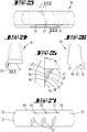
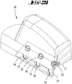
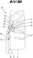
- the FIGS. 20 to 30 show a chamfering machine.
- the chamfer 50 has a plastic body consisting of a handle portion and a guide portion.
- the guide portion forms a guide niche 53.
- the guide niche 53 is formed by a support flank 51, which rests on the use of the planer 50 on a broad side 7 of a plasterboard 6.
- the Anflageflanke 52 serves to bear the planer 50 to a narrow side edge of a plasterboard 6, and is formed by a strip-like extension.
- the planer 50 has in the cutting direction successive blades 54, 55, 56.
- the three blades each have a pointing in the same direction cutting 54 ', 55', 56 '.
- the blades 54, 55, 56 are spaced from each other in the cutting direction.
- a chip outlet opening 57 In the cutting direction in front of the cutting edge 54 'of the first blade 54 is a chip outlet opening 57. In the cutting direction in front of the cutting edge 55' of the blade 55 is a chip outlet opening 58. In the cutting direction in front of the cutting edge 56 'of the blade 56 is another chip outlet opening 59th
- the chip outlet openings 57, 58, 59 form windows in the region of the strip-shaped section of the planer 50, which forms the contact edge 52 and is connected in the same material as the main body forming the support flank 51.
- the three blades 54, 55, 56 are inclined by a chamfer angle ⁇ with respect to both the abutment flank 52 and the support flank 51.
- the triangles are similar to each other.
- the triangle formed by the cutting edge 54 'of the first blade 54 is the smallest triangle.
- the triangle formed by the cutting edge 55 'of the second blade 54 has a larger cross-sectional area.
- the triangle formed by the last cutting blade 56 and its cutting edge 56 'in the cutting direction has the largest cross-sectional area.
- the blades 54, 55, 56 extend in parallel planes to each other, but have different distances to the abutment edge 52nd
- FIG. 20 shows a section line XXX, which at an angle to the section line XXIX in FIG. 21 is inclined.
- the cutting edges 54 ', 55', 56 ' extend along the inclined by the angle ⁇ line.
- FIG. 23 shows that the section line XXX beyond by an angle ⁇ with respect to in FIG. 21 with XXIX cross-sectional plane inclined.
- the blades 54, 55, 56 extend perpendicular to the cutting plane of the in FIG. 30 shown section. They thus have an angle of attack ⁇ to the chamfer surface plane.
- the angle of attack ⁇ is a rake angle for peeling off the strips of material.
- the chip outlet openings 57, 58, 59 are closed to the downwardly facing free edge of the abutment edge 52 and of the abutment edge 52 forming strip-shaped portion.
- Each webs 60 are formed.
- the webs 60 form a continuous strip between the two ends of the abutment edge 52 facing away from one another.
- the attachment openings 61 open into the support flank 51. Attachment openings 61 extend in the in the FIG. 30 illustrated section plane.
- the attachment opening 61 has a hexagonal cross section, so that a nut 66 rotatably receives therein.
- the mouth 61 'of the attachment opening 61 is located in the support flank 51.
- a fastening screw 65 is provided, the head of which is supported on the bottom of a fastening opening 64 of a retaining plate 63. The threaded shank of the fastening screw 65 is screwed into the nut 66.
- the holding plate 63 is substantially positively in the recess 62 and acts on the blades 54, 55, 56 against a flat contact surface against which the blades 54, 55, 56 lie flat. To change the blades, the three fastening screws 65 must be removed from the nuts 66 so that the retaining plate 63 can be removed.
- the device 50 is used to create a chamfer on a narrow side of a plasterboard panel.
- the three blades 54, 55, 56 engage in the cutting direction successively cutting into the plasterboard, the cutting edge 54 'of the blade lying in the cutting direction 54 a triangular in cross-section strips from the narrow side of the plasterboard 6 from.
- the respective blades 55, 56 lying in the cutting direction at the rear of the blade 54 each cut trapezoidal strips in cross-section from the narrow side of the plasterboard panel 6.
- the cut strips leave the guide niche 53 by the round-surrounded chip outlet openings 57, 58, 59th ⁇ b> ⁇ u> List of Reference Numbers ⁇ / u> ⁇ /b> 50 slicer 65 fixing screw 51 contact flank 66 mother 52 bearing flank 67 Handle 53 leadership niche 68 sloping flank 53 ' Shnittline 70 bag 54 blade 71 fastener 54 ' cutting edge ⁇ bevel angle 55 blade ⁇ angle of attack 55 ' vagina ⁇ angle 56 blade 56 ' cutting edge 57 Span outlet opening 58 Span outlet opening 59 Span outlet opening 60 web 61 fastening opening 62 deepening 63 Retaining plate 64 fastening opening
Landscapes
- Life Sciences & Earth Sciences (AREA)
- Forests & Forestry (AREA)
- Engineering & Computer Science (AREA)
- Mechanical Engineering (AREA)
- Knives (AREA)
- Details Of Cutting Devices (AREA)
- Perforating, Stamping-Out Or Severing By Means Other Than Cutting (AREA)
Priority Applications (2)
| Application Number | Priority Date | Filing Date | Title |
|---|---|---|---|
| PL17177551T PL3278941T3 (pl) | 2016-08-04 | 2016-08-04 | Przyrząd do montażu na sucho płyt gipsowo-kartonowych |
| EP17177551.3A EP3278941B1 (de) | 2016-08-04 | 2016-08-04 | Vorrichtung zur verwendung beim trockenausbau |
Applications Claiming Priority (2)
| Application Number | Priority Date | Filing Date | Title |
|---|---|---|---|
| EP16182778.7A EP3278940B1 (de) | 2016-08-04 | 2016-08-04 | Vorrichtung zur verwendung beim trockenausbau |
| EP17177551.3A EP3278941B1 (de) | 2016-08-04 | 2016-08-04 | Vorrichtung zur verwendung beim trockenausbau |
Related Parent Applications (2)
| Application Number | Title | Priority Date | Filing Date |
|---|---|---|---|
| EP16182778.7A Division EP3278940B1 (de) | 2016-08-04 | 2016-08-04 | Vorrichtung zur verwendung beim trockenausbau |
| EP16182778.7A Division-Into EP3278940B1 (de) | 2016-08-04 | 2016-08-04 | Vorrichtung zur verwendung beim trockenausbau |
Publications (2)
| Publication Number | Publication Date |
|---|---|
| EP3278941A1 EP3278941A1 (de) | 2018-02-07 |
| EP3278941B1 true EP3278941B1 (de) | 2019-09-25 |
Family
ID=56571242
Family Applications (2)
| Application Number | Title | Priority Date | Filing Date |
|---|---|---|---|
| EP17177551.3A Active EP3278941B1 (de) | 2016-08-04 | 2016-08-04 | Vorrichtung zur verwendung beim trockenausbau |
| EP16182778.7A Active EP3278940B1 (de) | 2016-08-04 | 2016-08-04 | Vorrichtung zur verwendung beim trockenausbau |
Family Applications After (1)
| Application Number | Title | Priority Date | Filing Date |
|---|---|---|---|
| EP16182778.7A Active EP3278940B1 (de) | 2016-08-04 | 2016-08-04 | Vorrichtung zur verwendung beim trockenausbau |
Country Status (2)
| Country | Link |
|---|---|
| EP (2) | EP3278941B1 (pl) |
| PL (1) | PL3278941T3 (pl) |
Families Citing this family (1)
| Publication number | Priority date | Publication date | Assignee | Title |
|---|---|---|---|---|
| DK180768B1 (en) * | 2020-04-23 | 2022-03-01 | Frontline Tools Aps | A drywall panel cutter |
Family Cites Families (21)
| Publication number | Priority date | Publication date | Assignee | Title |
|---|---|---|---|---|
| US1366800A (en) * | 1919-07-23 | 1921-01-25 | Zerah G Hayden | Combination-rule and adjustable compass |
| US2098641A (en) | 1936-04-15 | 1937-11-09 | Bigelow Sanford Carpet Co Inc | Strip cutter |
| US2208412A (en) * | 1939-06-14 | 1940-07-16 | Doniger Sundel | Tool guide |
| US2835037A (en) | 1956-06-27 | 1958-05-20 | John R Middents | Adjustable t-square head for mat cutters and similar devices |
| US3644993A (en) * | 1970-02-09 | 1972-02-29 | Leland Chupp | Edge-trimming device |
| FR2120206A5 (pl) | 1970-09-02 | 1972-08-18 | Dalami Dalles Prod Amian | |
| FR2144914A5 (pl) * | 1971-07-02 | 1973-02-16 | Kodak Pathe | |
| US4279081A (en) * | 1979-10-02 | 1981-07-21 | National Gypsum Company | Wallboard T-square |
| DE3624429C1 (en) | 1986-07-18 | 1987-10-08 | Johann Weiss | Device for scoring and cutting webs and/or boards with relatively hard and/or solid outer layers over a relatively soft and/or light core layer |
| DE8703786U1 (de) | 1987-03-13 | 1987-05-14 | Rigips GmbH, 3452 Bodenwerder | Kantenhobel für Gipskartonplatten |
| US4903409A (en) | 1989-05-19 | 1990-02-27 | Kaplan Stuart N | Drywall scribing and scoring tool |
| US5230152A (en) * | 1991-12-04 | 1993-07-27 | Kennedy Michael J | Dual blade utility knife |
| US5231764A (en) | 1992-06-03 | 1993-08-03 | Kenneth Chang | Cutter for a plasterboard sheet |
| US5471749A (en) * | 1994-11-01 | 1995-12-05 | Brady; John R. | Non-slip sewing ruler |
| DE19629202C2 (de) | 1996-07-19 | 2000-02-24 | Roessig Rolf | Kantenhobel |
| US5946808A (en) * | 1997-05-21 | 1999-09-07 | Martinez; Salomon C. | Guidance system and straight edge for cutting vinyl or carpet and floor covering materials and sheet goods |
| US5906049A (en) * | 1998-02-09 | 1999-05-25 | Butts; Robert | Double-ended utility knife with two covers |
| CA2533848C (en) * | 2005-01-24 | 2010-03-16 | Gary Mccallum | Wallboard cutting tool |
| FR2959155B1 (fr) | 2010-04-21 | 2012-07-20 | Benoit Mallet | Chariot de decoupe d'un panneau de carton-platre, kit de decoupe et procede de mise en oeuvre |
| US8434235B2 (en) | 2010-07-28 | 2013-05-07 | Gary McCallum | Utility knife blade release mechanism |
| US20120234150A1 (en) * | 2010-09-27 | 2012-09-20 | Mr. Joseph John Holtgreive | Tool and method for controlled cutting |
-
2016
- 2016-08-04 EP EP17177551.3A patent/EP3278941B1/de active Active
- 2016-08-04 PL PL17177551T patent/PL3278941T3/pl unknown
- 2016-08-04 EP EP16182778.7A patent/EP3278940B1/de active Active
Non-Patent Citations (1)
| Title |
|---|
| None * |
Also Published As
| Publication number | Publication date |
|---|---|
| EP3278941A1 (de) | 2018-02-07 |
| EP3278940A1 (de) | 2018-02-07 |
| EP3278940B1 (de) | 2020-07-29 |
| PL3278941T3 (pl) | 2020-03-31 |
Similar Documents
| Publication | Publication Date | Title |
|---|---|---|
| DE202015104380U1 (de) | Zerkleinerungsmaschine und Messer und Messersatz dieser Zerkleinerungsmaschine | |
| DE202014102469U1 (de) | Befestigungseinrichtung für einen Holm oder eine Leiste an einem C-Profil | |
| EP3138674B1 (de) | Vorrichtung zur durchführung von gehrungsschnitten | |
| EP2484471A1 (de) | Bearbeitungswerkzeug | |
| EP3167988B1 (de) | Lochsäge | |
| DE102013105257B4 (de) | Doppelkeil zum Rahmensetzen | |
| DE102006030825B4 (de) | Werkzeugträger für eine Führungsschiene einer Handwerkzeugmaschine | |
| WO2017020921A1 (de) | Käfigmutter | |
| DE102018004359A1 (de) | Objekthalteeinrichtung zur Anordnung an einem Profilstab | |
| DE4224665C2 (de) | Scherblattträger einer Heckenschere | |
| DE102010030893A1 (de) | Schraube | |
| DE202016102206U1 (de) | Funktionselement | |
| EP3695748A1 (de) | Einbauschrankanordnung | |
| DE202017000940U1 (de) | Befestigungsteil und Dachanordnung | |
| EP3278940A1 (de) | Vorrichtung zur verwendung beim trockenausbau | |
| DE202008005209U1 (de) | Werkzeugkopfanordnung | |
| DE19929477A1 (de) | Schneidmesser | |
| DE102005007451B4 (de) | Feststeller für Rückwände an Kastenmöbeln | |
| DE102022125475B4 (de) | Wasserstrahlschneideverfahren | |
| DE202023106463U1 (de) | Verbindungssystem zum Verbinden einer Mehrzahl von Profilleisten und Zentralelement zur Verwendung mit einem Verbindungssystem zum Verbinden einer Mehrzahl von Profilleisten | |
| EP2656990B1 (de) | Schieferschere | |
| DE202015009851U1 (de) | Lochsäge | |
| DE202007008325U1 (de) | Bohrschraube mit sechs Schneiden | |
| DE1950840C3 (de) | Leiste zur Befestigung von Verkleidungsteilen | |
| DE102022125476A1 (de) | Befestigungsvorrichtung für ein Werkstück |
Legal Events
| Date | Code | Title | Description |
|---|---|---|---|
| PUAI | Public reference made under article 153(3) epc to a published international application that has entered the european phase |
Free format text: ORIGINAL CODE: 0009012 |
|
| STAA | Information on the status of an ep patent application or granted ep patent |
Free format text: STATUS: THE APPLICATION HAS BEEN PUBLISHED |
|
| AC | Divisional application: reference to earlier application |
Ref document number: 3278940 Country of ref document: EP Kind code of ref document: P |
|
| AK | Designated contracting states |
Kind code of ref document: A1 Designated state(s): AL AT BE BG CH CY CZ DE DK EE ES FI FR GB GR HR HU IE IS IT LI LT LU LV MC MK MT NL NO PL PT RO RS SE SI SK SM TR |
|
| AX | Request for extension of the european patent |
Extension state: BA ME |
|
| STAA | Information on the status of an ep patent application or granted ep patent |
Free format text: STATUS: REQUEST FOR EXAMINATION WAS MADE |
|
| 17P | Request for examination filed |
Effective date: 20180427 |
|
| RBV | Designated contracting states (corrected) |
Designated state(s): AL AT BE BG CH CY CZ DE DK EE ES FI FR GB GR HR HU IE IS IT LI LT LU LV MC MK MT NL NO PL PT RO RS SE SI SK SM TR |
|
| GRAP | Despatch of communication of intention to grant a patent |
Free format text: ORIGINAL CODE: EPIDOSNIGR1 |
|
| STAA | Information on the status of an ep patent application or granted ep patent |
Free format text: STATUS: GRANT OF PATENT IS INTENDED |
|
| RIC1 | Information provided on ipc code assigned before grant |
Ipc: B27G 17/02 20060101ALI20190313BHEP Ipc: B26B 29/06 20060101AFI20190313BHEP |
|
| INTG | Intention to grant announced |
Effective date: 20190404 |
|
| GRAS | Grant fee paid |
Free format text: ORIGINAL CODE: EPIDOSNIGR3 |
|
| GRAA | (expected) grant |
Free format text: ORIGINAL CODE: 0009210 |
|
| STAA | Information on the status of an ep patent application or granted ep patent |
Free format text: STATUS: THE PATENT HAS BEEN GRANTED |
|
| AC | Divisional application: reference to earlier application |
Ref document number: 3278940 Country of ref document: EP Kind code of ref document: P |
|
| AK | Designated contracting states |
Kind code of ref document: B1 Designated state(s): AL AT BE BG CH CY CZ DE DK EE ES FI FR GB GR HR HU IE IS IT LI LT LU LV MC MK MT NL NO PL PT RO RS SE SI SK SM TR |
|
| REG | Reference to a national code |
Ref country code: GB Ref legal event code: FG4D Free format text: NOT ENGLISH |
|
| REG | Reference to a national code |
Ref country code: CH Ref legal event code: EP |
|
| REG | Reference to a national code |
Ref country code: AT Ref legal event code: REF Ref document number: 1183360 Country of ref document: AT Kind code of ref document: T Effective date: 20191015 |
|
| REG | Reference to a national code |
Ref country code: IE Ref legal event code: FG4D Free format text: LANGUAGE OF EP DOCUMENT: GERMAN |
|
| REG | Reference to a national code |
Ref country code: DE Ref legal event code: R096 Ref document number: 502016006845 Country of ref document: DE |
|
| REG | Reference to a national code |
Ref country code: NL Ref legal event code: MP Effective date: 20190925 |
|
| PG25 | Lapsed in a contracting state [announced via postgrant information from national office to epo] |
Ref country code: BG Free format text: LAPSE BECAUSE OF FAILURE TO SUBMIT A TRANSLATION OF THE DESCRIPTION OR TO PAY THE FEE WITHIN THE PRESCRIBED TIME-LIMIT Effective date: 20191225 Ref country code: NO Free format text: LAPSE BECAUSE OF FAILURE TO SUBMIT A TRANSLATION OF THE DESCRIPTION OR TO PAY THE FEE WITHIN THE PRESCRIBED TIME-LIMIT Effective date: 20191225 Ref country code: HR Free format text: LAPSE BECAUSE OF FAILURE TO SUBMIT A TRANSLATION OF THE DESCRIPTION OR TO PAY THE FEE WITHIN THE PRESCRIBED TIME-LIMIT Effective date: 20190925 Ref country code: FI Free format text: LAPSE BECAUSE OF FAILURE TO SUBMIT A TRANSLATION OF THE DESCRIPTION OR TO PAY THE FEE WITHIN THE PRESCRIBED TIME-LIMIT Effective date: 20190925 Ref country code: LT Free format text: LAPSE BECAUSE OF FAILURE TO SUBMIT A TRANSLATION OF THE DESCRIPTION OR TO PAY THE FEE WITHIN THE PRESCRIBED TIME-LIMIT Effective date: 20190925 Ref country code: SE Free format text: LAPSE BECAUSE OF FAILURE TO SUBMIT A TRANSLATION OF THE DESCRIPTION OR TO PAY THE FEE WITHIN THE PRESCRIBED TIME-LIMIT Effective date: 20190925 |
|
| REG | Reference to a national code |
Ref country code: LT Ref legal event code: MG4D |
|
| PG25 | Lapsed in a contracting state [announced via postgrant information from national office to epo] |
Ref country code: GR Free format text: LAPSE BECAUSE OF FAILURE TO SUBMIT A TRANSLATION OF THE DESCRIPTION OR TO PAY THE FEE WITHIN THE PRESCRIBED TIME-LIMIT Effective date: 20191226 Ref country code: RS Free format text: LAPSE BECAUSE OF FAILURE TO SUBMIT A TRANSLATION OF THE DESCRIPTION OR TO PAY THE FEE WITHIN THE PRESCRIBED TIME-LIMIT Effective date: 20190925 Ref country code: LV Free format text: LAPSE BECAUSE OF FAILURE TO SUBMIT A TRANSLATION OF THE DESCRIPTION OR TO PAY THE FEE WITHIN THE PRESCRIBED TIME-LIMIT Effective date: 20190925 |
|
| PG25 | Lapsed in a contracting state [announced via postgrant information from national office to epo] |
Ref country code: IT Free format text: LAPSE BECAUSE OF FAILURE TO SUBMIT A TRANSLATION OF THE DESCRIPTION OR TO PAY THE FEE WITHIN THE PRESCRIBED TIME-LIMIT Effective date: 20190925 Ref country code: RO Free format text: LAPSE BECAUSE OF FAILURE TO SUBMIT A TRANSLATION OF THE DESCRIPTION OR TO PAY THE FEE WITHIN THE PRESCRIBED TIME-LIMIT Effective date: 20190925 Ref country code: AL Free format text: LAPSE BECAUSE OF FAILURE TO SUBMIT A TRANSLATION OF THE DESCRIPTION OR TO PAY THE FEE WITHIN THE PRESCRIBED TIME-LIMIT Effective date: 20190925 Ref country code: NL Free format text: LAPSE BECAUSE OF FAILURE TO SUBMIT A TRANSLATION OF THE DESCRIPTION OR TO PAY THE FEE WITHIN THE PRESCRIBED TIME-LIMIT Effective date: 20190925 Ref country code: EE Free format text: LAPSE BECAUSE OF FAILURE TO SUBMIT A TRANSLATION OF THE DESCRIPTION OR TO PAY THE FEE WITHIN THE PRESCRIBED TIME-LIMIT Effective date: 20190925 Ref country code: PT Free format text: LAPSE BECAUSE OF FAILURE TO SUBMIT A TRANSLATION OF THE DESCRIPTION OR TO PAY THE FEE WITHIN THE PRESCRIBED TIME-LIMIT Effective date: 20200127 Ref country code: ES Free format text: LAPSE BECAUSE OF FAILURE TO SUBMIT A TRANSLATION OF THE DESCRIPTION OR TO PAY THE FEE WITHIN THE PRESCRIBED TIME-LIMIT Effective date: 20190925 |
|
| PG25 | Lapsed in a contracting state [announced via postgrant information from national office to epo] |
Ref country code: IS Free format text: LAPSE BECAUSE OF FAILURE TO SUBMIT A TRANSLATION OF THE DESCRIPTION OR TO PAY THE FEE WITHIN THE PRESCRIBED TIME-LIMIT Effective date: 20200224 Ref country code: CZ Free format text: LAPSE BECAUSE OF FAILURE TO SUBMIT A TRANSLATION OF THE DESCRIPTION OR TO PAY THE FEE WITHIN THE PRESCRIBED TIME-LIMIT Effective date: 20190925 Ref country code: SM Free format text: LAPSE BECAUSE OF FAILURE TO SUBMIT A TRANSLATION OF THE DESCRIPTION OR TO PAY THE FEE WITHIN THE PRESCRIBED TIME-LIMIT Effective date: 20190925 Ref country code: SK Free format text: LAPSE BECAUSE OF FAILURE TO SUBMIT A TRANSLATION OF THE DESCRIPTION OR TO PAY THE FEE WITHIN THE PRESCRIBED TIME-LIMIT Effective date: 20190925 |
|
| REG | Reference to a national code |
Ref country code: DE Ref legal event code: R097 Ref document number: 502016006845 Country of ref document: DE |
|
| PG2D | Information on lapse in contracting state deleted |
Ref country code: IS |
|
| PG25 | Lapsed in a contracting state [announced via postgrant information from national office to epo] |
Ref country code: DK Free format text: LAPSE BECAUSE OF FAILURE TO SUBMIT A TRANSLATION OF THE DESCRIPTION OR TO PAY THE FEE WITHIN THE PRESCRIBED TIME-LIMIT Effective date: 20190925 Ref country code: IS Free format text: LAPSE BECAUSE OF FAILURE TO SUBMIT A TRANSLATION OF THE DESCRIPTION OR TO PAY THE FEE WITHIN THE PRESCRIBED TIME-LIMIT Effective date: 20200126 |
|
| PLBE | No opposition filed within time limit |
Free format text: ORIGINAL CODE: 0009261 |
|
| STAA | Information on the status of an ep patent application or granted ep patent |
Free format text: STATUS: NO OPPOSITION FILED WITHIN TIME LIMIT |
|
| 26N | No opposition filed |
Effective date: 20200626 |
|
| PG25 | Lapsed in a contracting state [announced via postgrant information from national office to epo] |
Ref country code: SI Free format text: LAPSE BECAUSE OF FAILURE TO SUBMIT A TRANSLATION OF THE DESCRIPTION OR TO PAY THE FEE WITHIN THE PRESCRIBED TIME-LIMIT Effective date: 20190925 |
|
| PG25 | Lapsed in a contracting state [announced via postgrant information from national office to epo] |
Ref country code: MC Free format text: LAPSE BECAUSE OF FAILURE TO SUBMIT A TRANSLATION OF THE DESCRIPTION OR TO PAY THE FEE WITHIN THE PRESCRIBED TIME-LIMIT Effective date: 20190925 |
|
| REG | Reference to a national code |
Ref country code: CH Ref legal event code: PL |
|
| PG25 | Lapsed in a contracting state [announced via postgrant information from national office to epo] |
Ref country code: LI Free format text: LAPSE BECAUSE OF NON-PAYMENT OF DUE FEES Effective date: 20200831 Ref country code: LU Free format text: LAPSE BECAUSE OF NON-PAYMENT OF DUE FEES Effective date: 20200804 Ref country code: CH Free format text: LAPSE BECAUSE OF NON-PAYMENT OF DUE FEES Effective date: 20200831 |
|
| REG | Reference to a national code |
Ref country code: BE Ref legal event code: MM Effective date: 20200831 |
|
| PG25 | Lapsed in a contracting state [announced via postgrant information from national office to epo] |
Ref country code: IE Free format text: LAPSE BECAUSE OF NON-PAYMENT OF DUE FEES Effective date: 20200804 Ref country code: BE Free format text: LAPSE BECAUSE OF NON-PAYMENT OF DUE FEES Effective date: 20200831 |
|
| PG25 | Lapsed in a contracting state [announced via postgrant information from national office to epo] |
Ref country code: TR Free format text: LAPSE BECAUSE OF FAILURE TO SUBMIT A TRANSLATION OF THE DESCRIPTION OR TO PAY THE FEE WITHIN THE PRESCRIBED TIME-LIMIT Effective date: 20190925 Ref country code: MT Free format text: LAPSE BECAUSE OF FAILURE TO SUBMIT A TRANSLATION OF THE DESCRIPTION OR TO PAY THE FEE WITHIN THE PRESCRIBED TIME-LIMIT Effective date: 20190925 Ref country code: CY Free format text: LAPSE BECAUSE OF FAILURE TO SUBMIT A TRANSLATION OF THE DESCRIPTION OR TO PAY THE FEE WITHIN THE PRESCRIBED TIME-LIMIT Effective date: 20190925 |
|
| PG25 | Lapsed in a contracting state [announced via postgrant information from national office to epo] |
Ref country code: MK Free format text: LAPSE BECAUSE OF FAILURE TO SUBMIT A TRANSLATION OF THE DESCRIPTION OR TO PAY THE FEE WITHIN THE PRESCRIBED TIME-LIMIT Effective date: 20190925 |
|
| REG | Reference to a national code |
Ref country code: AT Ref legal event code: MM01 Ref document number: 1183360 Country of ref document: AT Kind code of ref document: T Effective date: 20210804 |
|
| PG25 | Lapsed in a contracting state [announced via postgrant information from national office to epo] |
Ref country code: AT Free format text: LAPSE BECAUSE OF NON-PAYMENT OF DUE FEES Effective date: 20210804 |
|
| P01 | Opt-out of the competence of the unified patent court (upc) registered |
Effective date: 20230513 |
|
| PGFP | Annual fee paid to national office [announced via postgrant information from national office to epo] |
Ref country code: DE Payment date: 20250821 Year of fee payment: 10 |
|
| PGFP | Annual fee paid to national office [announced via postgrant information from national office to epo] |
Ref country code: PL Payment date: 20250724 Year of fee payment: 10 |
|
| PGFP | Annual fee paid to national office [announced via postgrant information from national office to epo] |
Ref country code: GB Payment date: 20250819 Year of fee payment: 10 |
|
| PGFP | Annual fee paid to national office [announced via postgrant information from national office to epo] |
Ref country code: FR Payment date: 20250819 Year of fee payment: 10 |