EP3278928B1 - Vorrichtung zum schleifen und/oder polieren eines schneidwerkzeuges - Google Patents
Vorrichtung zum schleifen und/oder polieren eines schneidwerkzeuges Download PDFInfo
- Publication number
- EP3278928B1 EP3278928B1 EP17001311.4A EP17001311A EP3278928B1 EP 3278928 B1 EP3278928 B1 EP 3278928B1 EP 17001311 A EP17001311 A EP 17001311A EP 3278928 B1 EP3278928 B1 EP 3278928B1
- Authority
- EP
- European Patent Office
- Prior art keywords
- disc
- grinding
- cutting edge
- cutting tool
- polishing
- Prior art date
- Legal status (The legal status is an assumption and is not a legal conclusion. Google has not performed a legal analysis and makes no representation as to the accuracy of the status listed.)
- Active
Links
Images

Classifications
-
- B—PERFORMING OPERATIONS; TRANSPORTING
- B24—GRINDING; POLISHING
- B24D—TOOLS FOR GRINDING, BUFFING OR SHARPENING
- B24D15/00—Hand tools or other devices for non-rotary grinding, polishing, or stropping
- B24D15/06—Hand tools or other devices for non-rotary grinding, polishing, or stropping specially designed for sharpening cutting edges
- B24D15/08—Hand tools or other devices for non-rotary grinding, polishing, or stropping specially designed for sharpening cutting edges of knives; of razors
- B24D15/081—Hand tools or other devices for non-rotary grinding, polishing, or stropping specially designed for sharpening cutting edges of knives; of razors with sharpening elements in interengaging or in mutual contact
- B24D15/082—Hand tools or other devices for non-rotary grinding, polishing, or stropping specially designed for sharpening cutting edges of knives; of razors with sharpening elements in interengaging or in mutual contact the elements being rotatable
-
- B—PERFORMING OPERATIONS; TRANSPORTING
- B24—GRINDING; POLISHING
- B24B—MACHINES, DEVICES, OR PROCESSES FOR GRINDING OR POLISHING; DRESSING OR CONDITIONING OF ABRADING SURFACES; FEEDING OF GRINDING, POLISHING, OR LAPPING AGENTS
- B24B3/00—Sharpening cutting edges, e.g. of tools; Accessories therefor, e.g. for holding the tools
- B24B3/36—Sharpening cutting edges, e.g. of tools; Accessories therefor, e.g. for holding the tools of cutting blades
- B24B3/54—Sharpening cutting edges, e.g. of tools; Accessories therefor, e.g. for holding the tools of cutting blades of hand or table knives
- B24B3/543—Sharpening cutting edges, e.g. of tools; Accessories therefor, e.g. for holding the tools of cutting blades of hand or table knives using hand or foot driven tools
Definitions
- the invention relates to a device for grinding and / or polishing as well as deburring and / or honing a cutting tool, preferably a household knife.
- Devices for grinding a cutting tool are also from the US 2013/0295824 A1 and the U.S. 2,475,110 , as well as the DE 297 03 326 U1 became known on which the preamble of the independent claim is based.
- Devices for grinding and / or polishing as well as deburring and / or honing are also sufficiently known from the prior art. For example, from the free encyclopedia under the term "grindstone" devices are known in which the abrasive is on blocks or round, if necessary. angular edges are also applied.
- the operator To grind a cutting tool, the operator must hold it in one hand and the cutting tool to be ground or polished in the other hand. The device must then be pulled by the operator over the cutting edge of the cutting tool to be ground or polished.
- This procedure has the disadvantage that the same angle should always be kept between the cutting edge and the cutting tool, if possible, in order to achieve a good grinding result. This is particularly difficult because both the cutting tool and the grinding tool have to be kept virtually free in the air by the operator, and therefore a high level of skill on the part of the operator is required.
- the invention is therefore based on the object of proposing a device that is easy to operate and moreover has an increased grinding effect.
- a device which has one disk each to the right and left of an essentially cylindrical device body, the two disks being releasably connected via an axis mounted inside the device body and the axis being rotatable relative to the device body, so that an operator when he has a cutting edge on one of the two Applies discs and pulls the device body over a surface that can grind and / or polish the cutting edge.
- the grinding also includes, in particular, deburring of the cutting edge, and the polishing includes removing the cutting edge of the cutting tool.
- the device according to the invention is used for grinding and / or polishing a cutting tool with a cutting edge which is ground either on one side or on both sides.
- Such cutting tools are in particular commercial household or kitchen knives.
- knives with a coarse serrated edge as well as any type of outdoor and / or folding knife are among the cutting tools in the sense of the present application.
- the operator of the inventive device for grinding and / or polishing only has to position the cutting tool on the surface in a first step so that the cutting edge of the cutting tool rests against one of the two disks. In a second step, the operator then has to pull the device body along the surface in order to grind and / or polish the cutting edge. Due to the fact that both the inventive device for grinding and / or polishing and the cutting tool rest on the surface, simplified and more precise positioning is possible so that an improved grinding and / or polishing result can be achieved.
- the invention is detached from the type of surface on which the device is drawn.
- the surface can be a table surface or a surface of a shelf, in particular a kitchen shelf.
- any object can serve as a surface which has an essentially flat surface, at least in sections, so that the cutting tool is on the surface positioned and the device according to the invention can be pulled over this section of the object.
- first and / or the second disk are detachably connected to the axle, so that it is or are exchangeable. Due to the fact that both the first and the second disk are detachably connected to the axle, they can easily be exchanged by the operator. This can be advantageous, for example, if one of the two disks has to be replaced, for example for reasons of age, or if the operator would like to better adapt the device for grinding and / or polishing to the cutting tool. In particular, if different cutting tools are to be ground and / or polished, it can be advantageous that the two disks are exchangeable in order to adapt the device exactly to the respective grinding tool.
- the device can thus be configured in such a way that one disk has a grinding means for grinding the cutting edge and the other disk has a means for removing the cutting edge, so that the cutting edge of the cutting tool can be both ground and honed.
- the advantageous development of the invention can in particular also provide that the first disk has a first turned threaded bolt and / or the second disk has a second turned threaded bolt, so that the first and / or the second disk can or can be detachably screwed to the axle . are. In this way, replacement, for example due to wear or a change in the grinding process, is relatively quick and easy.
- the first disk has a first abrasive and the first abrasive has ruby, sapphire, diamond, glass, ceramic, corundum or carbide or a combination of the materials mentioned.
- the second disk is designed for polishing, so that when the cutting edge of the cutting tool is placed against the second disk and the device body is drawn, preferably by hand, over the surface, the second disk due to the Rotation or rotation polishes the cutting edge.
- the advantageous development can in particular provide that the second disk is designed in such a way that at least one depression is provided which is essentially concentric to the center point of the second disk.
- the second disk is also designed for grinding and has a second abrasive and the second abrasive has ruby, sapphire, diamond, glass, ceramic, corundum or carbide or a combination of the materials mentioned.
- the development provides that the first and second grinding means are different, so that the first and the second disk achieve a different grinding effect. Due to the different grinding effect of the two disks, it is possible, for example, for the first disk to be used for a rough grinding of the cutting edge and for the second disk to be used for a fine grinding of the cutting edge in order to achieve the most perfect possible grinding result.
- Figure 1 shows the inventive device for grinding and / or polishing 1 in a side view.
- the device 1 comprises an im Essentially cylindrical device body 2, which is made for example from a wood, and preferably has a diameter of a few centimeters.
- the device body 2 is designed in its shape and texture such that it lies as well as possible in the hand of an operator, so that the operator can grip the device body 2 with his hand as easily as possible and pull it over a surface when using the device 1.
- an axis 3 that is rotatably mounted relative to the device body 2 is formed.
- the axis 3 runs from the end face to a side facing away from the end face in the interior of the device body 2 and is designed in its two ends in such a way that a respective disk 4, 5 can be detachably attached.
- the inventive device for grinding and / or polishing 1 further comprises a first and a second circular disk 4, 5, one disk 4 on the first end face and the other disk 5 on the side of the device body 2 with the axis 3 facing away from the end face being detachable are connected.
- the detachable attachment of the two disks 4, 5 to the axis 3 allows the device for grinding and / or polishing 1 to be adapted as desired.
- the device 1 can thus be adapted to different cutting tools.
- a turned threaded bolt 11, 12 is preferably formed on each disk, via which the respective disk 4, 5 can be detachably attached to the axle 3.
- the invention is not limited to the two disks 4, 5 being releasably connectable to the axle 3, for example via the respective threaded bolts 11, 12. So it is also conceivable that a of the two disks and only the other of the two disks is detachably connected to the axle.
- the first disk 4 has a first grinding means for grinding the cutting edge of the cutting tool.
- the first abrasive preferably comprises ruby, sapphire, diamond, glass, ceramic, corundum or carbide. Furthermore, the first abrasive can also have a combination of the aforementioned materials. With the aid of the first disk 4 and the first grinding means, the cutting edge of the cutting tool can be ground by positioning the cutting tool on the surface and then pulling the device body 2 over the surface for grinding.
- the second disk 5 can on the one hand be designed so that it is used either for polishing or for grinding the cutting edge of the cutting tool.
- Fig. 1 This is indicated by the reference symbols 8 and 10 separated by a semicolon.
- the second disk 5 In the event that the second disk 5 is to be used for polishing, it has at least one, preferably several, depression or depressions 8 essentially concentric to the center point of the second disk. Due to the depression or depressions 8, an improved polishing effect is achieved by the rotation of the second disk 5 brought about when the device body 2 is pulled over the surface.
- the second disc 5 can, however, also have a second abrasive means 10, which preferably comprises ruby, sapphire, diamond, glass, ceramic, corundum or carbide. Furthermore, the second abrasive means 10 can also have a combination of the aforementioned materials.
- the second grinding means is preferably designed in such a way that the second wheel 5 with the second grinding means has a different grinding effect than the first wheel 4 with the first grinding means.
- the different The grinding effect can be implemented in different ways. For example, the different grinding effect can be achieved in that the first and the second grinding means comprise different grinding materials, the aforementioned materials. Furthermore, it can also be achieved by a different grain size applied to the panes.
- the material grains consisting of the aforementioned materials, in particular the diamond grains, per surface area, which is formed differently on the individual discs, can lead to the different grinding effect.
- the corresponding abrasive is galvanically wound onto the disks so that the abrasive effect can also be adapted via the very variable controllable thickness of the nickel layer around the grains.
- the two disks each include a circumferential rubber ring 6, 7.
- the rubber rings are each fixed by a groove surrounding the respective disk, so that on the one hand they do not can slip but are still interchangeable.
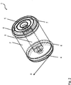
- FIG. 11 shows a perspective view of the FIG Fig. 1 shown and described above device according to the invention 1.
- the in Fig. 2 The device 1 shown is configured in such a way that the first disk 4 is used for grinding and the second disk 5 is used for polishing the cutting edge of the cutting tool.
- the cutting edge of the cutting tool can be ground in a first step.
- the cutting edge of the cutting tool is placed on the surface and positioned in relation to the first disk 4 of the device 1.
- the device body 2 is pulled along the surface by the operator. In Fig. 2 this pulling movement is indicated by the arrow "A".
- the pulling motion causes the first disc 4 instead, which in turn ensures that the cutting edge is ground.
- the cutting edge is repositioned to the device 1. This time, however, not to the first disk 4, but to the second disk 5, which is used to polish the cutting edge of the cutting tool. Again, the device body 2 is pulled along the surface by the operator, so that the polishing of the cutting edge of the cutting tool takes place through the pulling movement and the associated rotation of the second disk 5. In this way, the cutting edge can be both sharpened and polished.
- the invention is not restricted to the example described above, but that the device 1 can also be configured or used in other ways.
- the second wheel 5 can also be used for grinding, so that a coarse grinding can be carried out with the first wheel 4 in a first step and a finer grinding of the cutting edge can be carried out in a second step with the second wheel 5.
- only one of the two disks of the device 1 according to the invention can be used either for grinding or for polishing the cutting edge of the cutting tool.
Landscapes
- Engineering & Computer Science (AREA)
- Mechanical Engineering (AREA)
- Finish Polishing, Edge Sharpening, And Grinding By Specific Grinding Devices (AREA)
- Polishing Bodies And Polishing Tools (AREA)
Description
- Die Erfindung bezieht sich auf eine Vorrichtung zum Schleifen und/oder Polieren sowie dem Entgraten und/oder Abziehen eines Schneidwerkzeuges, vorzugsweise eines Haushaltsmessers.
- Aus der
US 1 388 882 A ist eine Vorrichtung zum Schleifen eines Schneidwerkzeuges bekannt geworden, bei der das Schneidwerkzeug zwischen einer Schleifscheibe und einer Führungsscheibe zum Schleifen eingespannt wird. - Vorrichtungen zum Schleifen eines Schneidwerkzeuges sind ferner auch aus der
US 2013/0295824 A1 und derUS 2 475 110 , sowie derDE 297 03 326 U1 bekannt geworden, auf welcher der Oberbegriff des unabhängigen Anspruchs basiert. Aus dem Stand der Technik sind ebenfalls Vorrichtungen zum Schleifen und/oder Polieren sowie dem Entgraten und/oder Abziehen hinlänglich bekannt. So sind bspw. aus der freien Enzyklopädie unter dem Begriff "Schleifstein" Vorrichtungen bekannt, bei denen das Schleifmittel auf Blöcke oder runde ggfl. auch eckige Kanten aufgebracht sind. Zum Schleifen eines Schneidwerkzeuges muss der Bediener dieses in einer Hand halten und in der anderen Hand das zu schleifende bzw. polierende Schneidwerkzeug. Die Vorrichtung muss dann von dem Bediener über die Schneide des zu schleifenden bzw. polierenden Schneidwerkezeuges gezogen werden. - Dieses Vorgehen weist den Nachteil auf, dass möglichst immer der gleiche Winkel zwischen der Schneide und dem Schneidwerkzeug gehalten werden sollte, um ein gutes Schleifergebnis zu erzielen. Dies ist insbesondere deshalb so schwierig, da sowohl das Schneidwerkzeug als auch das Schleifwerkzeug von dem Bediener quasi frei in der Luft gehalten werden müssen und somit eine hohe Geschicklichkeit des Bedieners gefragt ist.
- Der Erfindung liegt daher die Aufgabe zugrunde, eine Vorrichtung vorzuschlagen, die einfach zu bedienen ist und darüber hinaus eine erhöhte Schleifwirkung aufweist.
- Die Aufgabe wird erfindungsgemäß durch die im Patentanspruch 1 genannten Merkmale gelöst. Vorteilhafte Weiterbildungen der Erfindung ergeben sich aus den Unteransprüchen.
- Erfindungsgemäß wird also eine Vorrichtung vorgeschlagen, die jeweils eine Scheibe rechts und links eines im Wesentlichen zylinderförmigen Vorrichtungskörpers aufweist, wobei die beiden Scheiben über eine im Inneren des Vorrichtungskörpers gelagerte Achse lösbar verbunden sind und die Achse relativ zu dem Vorrichtungskörper rotierbar ist, so dass ein Bediener, wenn er eine Schneide des Schneidwerkzeugs an einer der beiden Scheiben anlegt und den Vorrichtungskörper über eine Oberfläche zieht, die Schneide schleifen und/oder polieren kann. Im Sinne der vorliegenden Anmeldung umfasst das Schleifen insbesondere auch ein Entgraten der Schneide und das Polieren umfasst ein Abziehen der Schneide des Schneidwerkzeuges.
- Die erfindungsgemäße Vorrichtung dient zum Schleifen und/oder Polieren eines Schneidwerkzeuges mit einer Schneide, welche entweder einseitig oder beidseitig geschliffen ist. Derartige Schneidwerkzeuge stellen insbesondere handelsübliche Haushalts- bzw. Küchenmesser dar. Aber auch Messer mit grobem Wellenschliff sowie jede Art von Outdoor- und/oder Klappmesser zählen zu den Schneidwerkzeugen im Sinne der vorliegenden Anmeldung.
- Im Gegensatz zu den aus dem Stand der Technik bekannten Schleifvorrichtungen muss der Bediener bei der erfindungsgemäßen Vorrichtung zum Schleifen und/oder Polieren in einem ersten Schritt lediglich das Schneidwerkzeug derartig auf der Oberfläche positionieren, dass die Schneide des Schneidwerkezeuges an einer der beiden Scheiben anliegt. In einem zweiten Schritt muss der Bediener anschließend den Vorrichtungskörper entlang der Oberfläche ziehen, um so die Schneide zu Schleifen und/oder Polieren. Aufgrund dessen, dass sowohl die erfindungsgemäße Vorrichtung zum Schleifen und/oder Polieren als auch das Schneidwerkzeug auf der Oberfläche aufliegen, ist eine vereinfachte und genauere Positionierung möglich, so dass ein verbessertes Schleif- und/oder Polierergebnis erzielbar ist.
- Die Erfindung ist dabei losgelöst von der Art der Oberfläche auf der die Vorrichtung entlang gezogen wird. So kann die Oberfläche bspw. eine Tischoberfläche oder auch eine Oberfläche einer Ablage, insbesondere einer Küchenablage, sein. Im Prinzip kann als Oberfläche jeglicher Gegenstand dienen, der eine zumindest abschnittsweise im Wesentlichen ebene Oberfläche aufweist, so dass das Schneidwerkzeug auf der Oberfläche positioniert und die erfindungsgemäße Vorrichtung über diesen Abschnitt des Gegenstandes gezogen werden kann.
- Eine vorteilhafte Weiterbildung der Erfindung sieht vor, dass die erste und/oder die zweite Scheibe lösbar mit der Achse verbunden sind, so dass diese austauschbar ist bzw. sind. Aufgrund dessen, dass sowohl die erste als auch die zweite Scheibe lösbar mit der Achse verbunden sind, können diese einfach durch den Bediener ausgetauscht werden. Dies kann bspw. dann von Vorteil sein, wenn ein der beiden Scheiben ersetzt werden muss, bspw. aus Altersgründen oder aber, wenn der Bediener die Vorrichtung zum Schleifen und/oder Polieren auf das Schneidwerkzeug besser anpassen möchte. Insbesondere wenn unterschiedliche Schneidwerkzeuge geschliffen und/oder poliert werden sollen, kann es von Vorteil sein, das die beiden Scheiben austauschbar sind, um so die Vorrichtung für das jeweilige Schleifwerkzeug exakt anzupassen. Beispielsweise kann die Vorrichtung somit derartig konfiguriert werden, dass eine Scheibe ein Schleifmittel zum Schleifen der Schneide und die andere Scheibe ein Mittel zum Abziehen der Schneide aufweist, so dass die Schneide des Schneidwerkzeuges sowohl geschliffen als auch abgezogen werden kann. Die vorteilhafte Weiterbildung der Erfindung kann insbesondere auch vorsehen, dass die erste Scheibe einen ersten angedrehten Gewindebolzen und/oder die zweite Scheibe einen zweiten angedrehten Gewindebolzen aufweist bzw. aufweisen, so dass die erste und/oder die zweite Scheibe mit der Achse lösbar verschraubbar ist bzw. sind. Auf diese Weise ist der Austausch, bspw. wegen Verschleiß oder Wechsel des Schleifverfahrens relativ schnell und einfach möglich.
- Eine weitere vorteilhafte Weiterbildung der Erfindung sieht vor, dass zumindest die erste Scheibe ein erstes Schleifmittel aufweist und das erste Schleifmittel Rubin, Saphir, Diamant, Glas, Keramik, Korund oder Karbid oder eine Kombination der genannten Materialien aufweist.
- Wiederum eine weitere vorteilhafte Weiterbildung der Erfindung sieht vor, dass die zweite Scheibe zum Polieren ausgebildet ist, so dass wenn die Schneide des Schneidwerkzeuges an die zweite Scheibe angelegt ist und der Vorrichtungskörper, vorzugsweise händisch, über die Oberfläche gezogen wird, die zweite Scheibe aufgrund der Drehung bzw. Rotation die Schneide poliert. Die vorteilhafte Weiterbildung kann insbesondere vorsehen, dass die zweite Scheibe derartig ausgebildet ist, dass zumindest eine im Wesentlichen zum Mittelpunkt der zweiten Scheibe konzentrische Vertiefung vorgesehen ist.
- Eine alternative Weiterbildung der Erfindung sieht vor, dass die zweite Scheibe ebenfalls zum Schleifen ausgebildet ist und ein zweites Schleifmittel aufweist und das zweite Schleifmittel Rubin, Saphir, Diamant, Glas, Keramik, Korund oder Karbid oder eine Kombination der genannten Materialien aufweist. Insbesondere sieht die Weiterbildung vor, dass das erste und zweite Schleifmittel unterschiedlich sind, so dass die erste und die zweite Scheibe eine unterschiedliche Schleifwirkung erzielen. Aufgrund der unterschiedlichen Schleifwirkung der beiden Scheiben ist es bspw. möglich, dass mit der ersten Scheibe eine grobe Schleifung der Schneide des Schneidwerkzeuges erfolgt und mit der zweiten Scheibe eine feine Schleifung der Schneide erfolgt, um so ein möglichst perfektes Schleifergebnis zu erzielen.
- Die Erfindung wird anhand der nachfolgenden Zeichnungen näher erläutert. Es zeigt:
-
Fig. 1 : eine Seitenansicht der erfindungsgemäßen Vorrichtung zum Schleifen und/oder Polieren, und -
Fig. 2 : eine perspektivische Ansicht der inFig. 1 dargestellten erfindungsgemäßen Vorrichtung. -
Figur 1 zeigt die erfindungsgemäße Vorrichtung zum Schleifen und/oder Polieren 1 in einer Seitenansicht. Die Vorrichtung 1 umfasst einen im Wesentlichen zylinderförmigen Vorrichtungskörper 2, der bspw. aus einem Holz hergestellt ist, und vorzugsweise einen Durchmesser von einigen Zentimetern aufweist. Der Vorrichtungskörper 2 ist dabei in seiner Form und Beschaffenheit derartig ausgebildet, dass er möglichst gut in der Hand eines Bedieners liegt, so dass der Bediener beim Einsatz der Vorrichtung 1 den Vorrichtungskörper 2 möglichst einfach mit seiner Hand greifen und über eine Oberfläche ziehen kann. - In dem Vorrichtungskörper 2 ist eine relativ zu dem Vorrichtungskörper 2 drehbar gelagerte Achse 3 ausgebildet. Die Achse 3 verläuft von der Stirnseite zu einer der Stirnseite abgewandten Seite im Inneren des Vorrichtungskörpers 2 und ist in ihren beiden Enden so ausgebildet, dass jeweils eine Scheibe 4, 5 lösbar anbringbar ist.
- Die erfindungsgemäße Vorrichtung zum Schleifen und/oder Polieren 1 umfasst ferner eine erste und eine zweite kreisrunde Scheibe 4, 5, wobei eine Scheibe 4 an der ersten Stirnseite und die andere Scheibe 5 an der der Stirnseite abgewandten Seite des Vorrichtungskörpers 2 mit der Achse 3 lösbar verbunden sind.
- Das lösbare Anbringen der beiden Scheiben 4, 5 an die Achse 3 erlaubt es, die Vorrichtung zum Schleifen und/oder Polieren 1 beliebig anzupassen. Beispielsweise kann die Vorrichtung 1 so an unterschiedliche Schneiderwerkzeuge angepasst werden. Aber auch das Austauschen einer alten oder auch defekten Scheibe ist somit problemlos möglich. Um einen besonders schnellen und einfachen Austausch der Scheiben zu ermöglichen, ist vorzugsweise an jeder Scheibe ein angedrehter Gewindebolzen 11, 12 ausgebildet, über den sich die jeweilige Scheibe 4, 5 an der Achse 3 lösbar anbringen lässt. Die Erfindung ist dabei nicht darauf beschränkt, dass beide Scheiben 4, 5 lösbar mit der Achse 3, bspw. über den jeweiligen Gewindebolzen 11, 12, verbindbar sind. So ist es ebenfalls denkbar, dass eine der beiden Scheiben fest und lediglich die andere der beiden Scheiben lösbar mit der Achse verbunden ist.
- Die erste Scheibe 4 weist ein erstes Schleifmittel zum Schleifen der Schneide des Schneidwerkzeuges auf. Das erste Schleifmittel umfasst vorzugsweise Rubin, Saphir, Diamant, Glas, Keramik, Korund oder Karbid. Ferner kann das erste Schleifmittel auch eine Kombination der zuvor genannten Materialen aufweisen. Mit Hilfe der ersten Scheibe 4 und des ersten Schleifmittels kann die Schneide des Schneidwerkzeuges geschliffen werden, in dem das Schneidwerkzeug auf der Oberfläche positioniert wird, und der Vorrichtungskörper 2 anschließend zum Schleifen über die Oberfläche gezogen wird.
- Die zweite Scheibe 5 kann einerseits so ausgebildet sein, dass sie entwerder zum Polieren oder zum Schleifen der Schneide des Schneidwerkzeuges dient. In
Fig. 1 ist diesem Sachverhalt durch die mit einem Semikolon getrennten Bezugszeichen 8 und 10 angedeutet. - In dem Fall, dass die zweite Scheibe 5 zum Polieren dienen soll, weist diese zumindest eine, vorzugsweise mehrere, im Wesentlichen zum Mittelpunkt der zweiten Scheibe konzentrische Vertiefung bzw. Vertiefungen 8 auf. Durch die Vertiefung bzw. Vertiefungen 8 wird durch die beim Ziehen des Vorrichtungskörpers 2 über die Oberfläche hervorgerufene Rotation der zweiten Scheibe 5 eine verbesserte Polierwirkung erzielt.
- Die zweite Scheibe 5 kann aber auch ein zweites Schleifmittel 10 aufweisen, welches vorzugsweise Rubin, Saphir, Diamant, Glas, Keramik, Korund oder Karbid umfasst. Ferner kann das zweite Schleifmittel 10 auch eine Kombination der zuvor genannten Materialen aufweisen. Das zweite Schleifmittel ist vorzugsweise derartig ausgebildet, dass die zweite Scheibe 5 mit dem zweiten Schleifmittel eine unterschiedliche Schleifwirkung zu der ersten Scheibe 4 mit dem ersten Schleifmittel aufweist. Die unterschiedliche Schleifwirkung kann dabei auf unterschiedliche Art und Weise realisiert werden. Bspw. kann die unterschiedliche Schleifwirkung dadurch erzielt werden, dass das erste und das zweite Schleifmittel unterschiedliche Schleifmaterialen, der zuvor genannten Materialien, umfassen. Ferner kann sie auch durch eine auf die Scheiben unterschiedlich aufgebrachte Körnung erzielt werden. Aber auch eine auf den einzelnen Scheiben unterschiedlich ausgebildete Dichte der aus den zuvor genannten Materialen bestehenden Materialkörner, insbesondere der Diamantkörner, pro Flächeninhalt kann zu der unterschiedlichen Schleifwirkung führen. Für gewöhnlich wird das entsprechende Schleifmittel galvanisch auf die Scheiben aufgenickelt, so dass auch über die sehr variabel steuerbare Dicke der Nickelschicht um die Körner herum die Schleifwirkung angepasst werden kann.
- Um eine einfache und leise Laufbewegung der beiden Scheiben beim Ziehen des Vorrichtungskörpers 2 über die Oberfläche zu erhalten, umfassen die beiden Scheiben jeweils einen umlaufenden Gummiring 6, 7. Die Gummiringe sind jeweils durch eine die jeweilige Scheibe umlaufenden Nut fixiert, so dass sie einerseits nicht verrutschen können, aber dennoch austauschbar sind.
-
Fig. 2 zeigt eine perspektivische Ansicht der inFig. 1 dargestellten und zuvor beschriebenen erfindungsgemäßen Vorrichtung 1. Die inFig. 2 dargestellte Vorrichtung 1 ist derartig konfiguriert, dass die erste Scheibe 4 zum Schleifen und die zweite Scheibe 5 zum Polieren der Schneide des Schneidwerkzeuges dient. - Mit Hilfe der derartig konfigurierten erfindungsgemäßen Vorrichtung 1 lässt sich die Schneide des Schneidwerkzeuges in einem ersten Schritt schleifen. Hierzu wird die Schneide des Schneidwerkzeuges auf der Oberfläche aufgesetzt und zu der ersten Scheibe 4 der Vorrichtung 1 entsprechend positioniert. Anschließend wird der Vorrichtungskörper 2 durch den Bediener entlang der Oberfläche gezogen. In
Fig. 2 ist diese Zugbewegung durch den Pfeil "A" angedeutet. Durch die Zugbewegung findet eine Drehbewegung der ersten Scheibe 4 statt, welche wiederum dafür sorgt, dass die Schneide geschliffen wird. - In einem zweiten Schritt, wird nach dem Schleifen die Schneide erneut zur Vorrichtung 1 positioniert. Diesmal jedoch nicht zur ersten Scheibe 4, sondern zur zweiten Scheibe 5, die zum Polieren der Schneide des Schneidwerkzeuges dient. Wiederum wird der Vorrichtungskörper 2 entlang der Oberfläche durch den Bediener gezogen, so dass durch die Zugbewegung und der damit einhergehenden Rotation der zweiten Scheibe 5 das Polieren der Schneide des Schneidwerkzeuges sattfindet. Auf diese Weise lässt sich die Schneide sowohl schleifen als auch polieren.
- Es versteht sich von selbst, dass die Erfindung nicht auf das zuvor beschriebene Beispiel beschränkt ist, sondern die Vorrichtung 1 auch anderweitig konfiguriert bzw. eingesetzt werden kann. Beispielsweise kann, wie bereits angedeutet, die zweite Scheibe 5 ebenfalls zum Schleifen dienen, so dass in einem ersten Schritt mit der ersten Scheibe 4 eine grobe Schleifung durchführbar und in einem zweiten Schritt mit der zweiten Scheibe 5 eine feinere Schleifung der Schneide durchführbar ist. Selbstverständlich kann auch nur eine der beiden Scheiben der erfindungsgemäßen Vorrichtung 1 entweder zum Schleifen oder zum Polieren der Schneide des Schneidwerkzeuges eingesetzt werden.
-
- 1
- Vorrichtung zum Schleifen und/oder Polieren
- 2
- Vorrichtungskörper
- 3
- Achse
- 4
- Erste Scheibe
- 5
- Zweite Scheibe
- 6
- Erster Gummiring
- 7
- Zweiter Gummiring
- 8
- Konzentrische Vertiefung
- 9
- Erstes Schleifmittel
- 10
- Zweites Schleifmittel
- 11
- Erster Gewindebolzen
- 12
- Zweiter Gewindebolzen
- A
- Zugbewegung
Claims (8)
- Vorrichtung zum Schleifen und/oder Polieren eines Schneidwerkzeuges, vorzugsweise eines Haushaltsmessers umfassend:- einen zylindrischen Vorrichtungskörper (2); gekennzeichnet durch- eine erste und eine zweite im Wesentlichen kreisrunde Scheibe (4, 5), die an unterschiedlichen axialen Enden des Vorrichtungskörpers (2) angeordnet und jeweils mit einer in dem Vorrichtungskörper (2) drehbar gelagerten Achse (3) verbunden sind, sodass wenn der Vorrichtungskörper (2) entlang einer Oberfläche, vorzugsweise einer Tischoberfläche, gezogen wird, sich die zwei Scheiben (4, 5) relativ zu dem Vorrichtungskörper (2) drehen bzw. rotieren und wobei zumindest die erste Scheibe (4) zum Schleifen ausgebildet und derartig beschaffen ist, dass wenn eine Schneide des Schneidwerkzeuges an die erste Scheibe (4) angelegt ist und der Vorrichtungskörper (2), vorzugsweise händisch, über die Oberfläche gezogen wird, die erste Scheibe (4) aufgrund der Drehung bzw. Rotation die Schneide schleift, wobei die erste Scheibe (4) an der Stirnseite eine Schleiffläche aufweist, wobei die zweite Scheibe (5) zum Schleifen oder Polieren des Schneidwerkzeuges ausgebildet ist und an der Stirnseite eine Schleif- oder Polierfläche aufweist, wobei sich die zwei Scheiben (4, 5) jeweils zur Stirnseite hin verjüngen.
- Vorrichtung nach Anspruch 1, wobei die erste und/oder die zweite Scheibe (4, 5) lösbar mit der Achse (3) verbunden sind, so dass diese austauschbar ist bzw. sind.
- Vorrichtung nach dem vorhergehenden Anspruch, wobei die erste Scheibe (4) einen ersten angedrehten Gewindebolzen (11) und/oder die zweite Scheibe (5) einen zweiten angedrehten Gewindebolzen (12) aufweist bzw. aufweisen, so dass die erste und/oder die zweite Scheibe (4, 5) mit der Achse (3) lösbar verschraubbar ist bzw. sind.
- Vorrichtung nach zumindest einem der Ansprüche 1 bis 3, wobei zumindest die erste Scheibe (4) ein erstes Schleifmittel (9) aufweist und das erste Schleifmittel (9) Rubin, Saphir, Diamant, Glas, Keramik, Korund oder Karbid oder eine Kombination der genannten Materialien aufweist.
- Vorrichtung nach zumindest einem der Ansprüche 1 bis 4, wobei ferner die zweite Scheibe (5) zum Polieren ausgebildet ist, so dass wenn die Schneide des Schneidwerkzeuges an die zweite Scheibe (5) angelegt ist und der Vorrichtungskörper (2), vorzugsweise händisch, über die Oberfläche gezogen wird, die zweite Scheibe (5) aufgrund der Drehung bzw. Rotation die Schneide poliert.
- Vorrichtung nach dem vorhergehenden Anspruch, wobei die zweite Scheibe (5) derartig ausgebildet ist, dass zumindest eine im Wesentlichen zum Mittelpunkt der zweiten Scheibe (5) konzentrische Vertiefung (8) vorgesehen ist.
- Vorrichtung nach zumindest einem der Ansprüche 1 bis 4, wobei die zweite Scheibe (5) ebenfalls zum Schleifen ausgebildet ist und ein zweites Schleifmittel (10) aufweist und das zweite Schleifmittel (10) Rubin, Saphir, Diamant, Glas, Keramik, Korund oder Karbid oder eine Kombination der genannten Materialien aufweist.
- Vorrichtung nach dem vorhergehenden Anspruch, wobei das erste und zweite Schleifmittel (9, 10) unterschiedlich sind, so dass die erste und die zweite Scheibe (4, 5) eine unterschiedliche Schleifwirkung erzielen.
Applications Claiming Priority (1)
| Application Number | Priority Date | Filing Date | Title |
|---|---|---|---|
| DE102016009482.6A DE102016009482B4 (de) | 2016-08-05 | 2016-08-05 | Vorrichtung zum Schleifen und/oder Polieren eines Schneidwerkzeuges |
Publications (4)
| Publication Number | Publication Date |
|---|---|
| EP3278928A2 EP3278928A2 (de) | 2018-02-07 |
| EP3278928A3 EP3278928A3 (de) | 2018-05-30 |
| EP3278928B1 true EP3278928B1 (de) | 2021-02-17 |
| EP3278928B2 EP3278928B2 (de) | 2025-11-26 |
Family
ID=59506048
Family Applications (1)
| Application Number | Title | Priority Date | Filing Date |
|---|---|---|---|
| EP17001311.4A Active EP3278928B2 (de) | 2016-08-05 | 2017-07-31 | Vorrichtung zum schleifen und/oder polieren eines schneidwerkzeuges |
Country Status (6)
| Country | Link |
|---|---|
| EP (1) | EP3278928B2 (de) |
| DE (3) | DE102016009482B4 (de) |
| DK (1) | DK3278928T4 (de) |
| ES (1) | ES2870051T3 (de) |
| FI (1) | FI3278928T4 (de) |
| PT (1) | PT3278928T (de) |
Cited By (1)
| Publication number | Priority date | Publication date | Assignee | Title |
|---|---|---|---|---|
| WO2022233998A1 (de) | 2021-05-05 | 2022-11-10 | Horl 1993 Gmbh | Schere, die zwischen einer schneid- und einer schleifkonfiguration überführbar ist |
Families Citing this family (21)
| Publication number | Priority date | Publication date | Assignee | Title |
|---|---|---|---|---|
| DE102016009482B4 (de) | 2016-08-05 | 2018-06-14 | Timo Horl | Vorrichtung zum Schleifen und/oder Polieren eines Schneidwerkzeuges |
| DE102020203144B4 (de) * | 2020-03-11 | 2022-06-15 | Horl 1993 Gmbh | Rollschleifer pro |
| DE202020001180U1 (de) | 2020-03-25 | 2020-04-23 | Mobiset Gmbh | Rollschleifer und Rollschleifer-Set |
| DE102020123499B4 (de) | 2020-09-09 | 2022-04-28 | Horl 1993 Gmbh | Verfahren zur Herstellung eines Rollschleifers mit minimalen Spaltmaßen zwischen Laufrolle und Griffkörper |
| DE102020123501B3 (de) | 2020-09-09 | 2022-03-10 | Horl 1993 Gmbh | Rollschleifer mit Presspassung zwischen Laufrolle und Achse |
| DE102020123503A1 (de) | 2020-09-09 | 2022-03-10 | Horl 1993 Gmbh | Schleiflehre mit einstellbarem Winkel |
| DE102020123500A1 (de) | 2020-09-09 | 2022-03-10 | Horl 1993 Gmbh | Magnet-Schleiflehre mit elastischem Kontaktelement |
| DE102020133853B3 (de) | 2020-12-16 | 2022-04-28 | Horl 1993 Gmbh | Schneidwerkzeug mit Auflageabschnitt für voreingestellten Schleifwinkel |
| DE202022001390U1 (de) | 2022-06-17 | 2022-07-07 | Magna-Tec e.K. | Vorrichtung zum Schleifen und/oder Polieren eines Schneidwerkzeuges |
| DE202022002459U1 (de) | 2022-11-16 | 2023-01-24 | Magna-Tec e.K. | Referenzebene zur Optimierung beim Schleifen mittels einer Rollschleif-Vorrichtung |
| US20240238931A1 (en) * | 2023-01-18 | 2024-07-18 | Konstantin Berger | Sharpening apparatus with magnetically attached sharpening wheels |
| DE102023106564A1 (de) | 2023-03-16 | 2024-09-19 | Horl 1993 Gmbh | Rollschleifer mit direkt verbundenen Laufrollen und Etui für Rollschleifer |
| DE102024104366A1 (de) * | 2024-02-16 | 2025-08-21 | Horl 1993 Gmbh | Magnet-Schleiflehre mit Träger für ein elastisches Kontaktelement |
| DE102024104413A1 (de) * | 2024-02-16 | 2025-08-21 | Horl 1993 Gmbh | Rollschleifer mit Schleifscheiben-Schnellverschluss-System |
| DE102024104397A1 (de) * | 2024-02-16 | 2025-08-21 | Horl 1993 Gmbh | Rollschleifer mit mehrteiligem, hohlem Körper |
| DE102024104350B4 (de) * | 2024-02-16 | 2025-09-04 | Horl 1993 Gmbh | Schleiflehre mit einstellbarem Winkel |
| DE102024104418A1 (de) | 2024-02-16 | 2025-08-21 | Horl 1993 Gmbh | Schneidwerkzeug, insbesondere Schere, mit federnd gegeneinander vorgespannten Klingen |
| DE102024104398A1 (de) | 2024-02-16 | 2025-08-21 | Horl 1993 Gmbh | Magnet-Schleiflehre mit mehrteiligem, hohlem Körper |
| DE102024108934A1 (de) * | 2024-03-28 | 2025-10-02 | Lorenz Kaczmarek | Schleifhilfe für einen Rollschleifer und Rollschleifer-Set |
| DE102024108935A1 (de) | 2024-03-28 | 2025-10-02 | Lorenz Kaczmarek | Rollschleifer und Rollschleifer-Set |
| DE202024002365U1 (de) | 2024-12-12 | 2025-01-10 | Mobiset Gmbh | Zum Nassschleifen geeigneter Messerschleifer |
Citations (8)
| Publication number | Priority date | Publication date | Assignee | Title |
|---|---|---|---|---|
| US948362A (en) * | 1908-04-23 | 1910-02-08 | John Allan Wilkinson | Sharpener for cutlery. |
| US1388882A (en) | 1920-09-29 | 1921-08-30 | Paul Adolf | Blade-sharpener |
| GB437733A (en) * | 1933-04-28 | 1935-10-28 | Thomas Holtan | Improvements in sharpening apparatus |
| US2475110A (en) | 1947-04-23 | 1949-07-05 | Leo E Pryor | Knife sharpener |
| DE29703326U1 (de) * | 1997-02-25 | 1997-06-12 | Horl, Otmar, 79110 Freiburg | Schleif- und Abziehwerkzeug, zum Schleifen von Schneiden, welches als selbsttreibende Rolle oder Scheibe mit Griff ausgebildet ist |
| US20130295824A1 (en) | 2012-05-03 | 2013-11-07 | Kabushiki Kaisha Suehiro | Blade Sharpener |
| EP3278928A2 (de) | 2016-08-05 | 2018-02-07 | Timo Horl | Vorrichtung zum schleifen und/oder polieren eines schneidwerkzeuges |
| DE202020001180U1 (de) | 2020-03-25 | 2020-04-23 | Mobiset Gmbh | Rollschleifer und Rollschleifer-Set |
Family Cites Families (2)
| Publication number | Priority date | Publication date | Assignee | Title |
|---|---|---|---|---|
| US2469797A (en) * | 1947-05-02 | 1949-05-10 | Alden Speare S Sons Co | Knife sharpener |
| DE1910417U (de) * | 1964-11-06 | 1965-02-18 | Theodor Jacob | Apparat zum schaerfen von messern. |
-
2016
- 2016-08-05 DE DE102016009482.6A patent/DE102016009482B4/de active Active
-
2017
- 2017-07-31 FI FIEP17001311.4T patent/FI3278928T4/fi active
- 2017-07-31 PT PT170013114T patent/PT3278928T/pt unknown
- 2017-07-31 ES ES17001311T patent/ES2870051T3/es active Active
- 2017-07-31 DK DK17001311.4T patent/DK3278928T4/da active
- 2017-07-31 DE DE202017007115.0U patent/DE202017007115U1/de active Active
- 2017-07-31 EP EP17001311.4A patent/EP3278928B2/de active Active
- 2017-07-31 DE DE202017007377.3U patent/DE202017007377U1/de active Active
Patent Citations (8)
| Publication number | Priority date | Publication date | Assignee | Title |
|---|---|---|---|---|
| US948362A (en) * | 1908-04-23 | 1910-02-08 | John Allan Wilkinson | Sharpener for cutlery. |
| US1388882A (en) | 1920-09-29 | 1921-08-30 | Paul Adolf | Blade-sharpener |
| GB437733A (en) * | 1933-04-28 | 1935-10-28 | Thomas Holtan | Improvements in sharpening apparatus |
| US2475110A (en) | 1947-04-23 | 1949-07-05 | Leo E Pryor | Knife sharpener |
| DE29703326U1 (de) * | 1997-02-25 | 1997-06-12 | Horl, Otmar, 79110 Freiburg | Schleif- und Abziehwerkzeug, zum Schleifen von Schneiden, welches als selbsttreibende Rolle oder Scheibe mit Griff ausgebildet ist |
| US20130295824A1 (en) | 2012-05-03 | 2013-11-07 | Kabushiki Kaisha Suehiro | Blade Sharpener |
| EP3278928A2 (de) | 2016-08-05 | 2018-02-07 | Timo Horl | Vorrichtung zum schleifen und/oder polieren eines schneidwerkzeuges |
| DE202020001180U1 (de) | 2020-03-25 | 2020-04-23 | Mobiset Gmbh | Rollschleifer und Rollschleifer-Set |
Cited By (1)
| Publication number | Priority date | Publication date | Assignee | Title |
|---|---|---|---|---|
| WO2022233998A1 (de) | 2021-05-05 | 2022-11-10 | Horl 1993 Gmbh | Schere, die zwischen einer schneid- und einer schleifkonfiguration überführbar ist |
Also Published As
| Publication number | Publication date |
|---|---|
| EP3278928B2 (de) | 2025-11-26 |
| DE202017007377U1 (de) | 2021-01-28 |
| DK3278928T3 (da) | 2021-05-10 |
| PT3278928T (pt) | 2021-04-28 |
| EP3278928A2 (de) | 2018-02-07 |
| FI3278928T4 (fi) | 2026-01-28 |
| DK3278928T4 (da) | 2026-02-16 |
| DE102016009482B4 (de) | 2018-06-14 |
| DE202017007115U1 (de) | 2019-08-07 |
| EP3278928A3 (de) | 2018-05-30 |
| ES2870051T3 (es) | 2021-10-26 |
| DE102016009482A1 (de) | 2018-02-08 |
Similar Documents
| Publication | Publication Date | Title |
|---|---|---|
| EP3278928B1 (de) | Vorrichtung zum schleifen und/oder polieren eines schneidwerkzeuges | |
| DE60101652T2 (de) | Schleifwerkzeug | |
| EP2835220B1 (de) | Abrichtwerkzeug sowie ein Verfahren zu dessen Herstellung | |
| DE202020001180U1 (de) | Rollschleifer und Rollschleifer-Set | |
| EP3746266B1 (de) | Messerschärfvorrichtung mit haltepunkten | |
| DE202022001390U1 (de) | Vorrichtung zum Schleifen und/oder Polieren eines Schneidwerkzeuges | |
| DE202012002267U1 (de) | Tellerschleifer einer Vorrichtung zum Entgraten und/oder Verrunden von metallenen Werkstücken im Durchlaufverfahren | |
| DE202012101515U1 (de) | Schleifmittel und Schleifwerkzeug | |
| WO2014131403A2 (de) | Schneidscheibe und trägerkörper eines schneidrads zur bildung einer fase | |
| AT523721B1 (de) | Vorrichtung zum Schleifen von Klingen | |
| DE19736248A1 (de) | Ultraschall-Vibrations-Verbundschleifwerkzeug | |
| DE102007045351B3 (de) | Segmentmesser | |
| DE19841386C2 (de) | Schleifvorrichtung zum Schleifen eines Randes eines Keramik- oder Porzellangegenstandes | |
| EP4434673A1 (de) | Messerschärfvorrichtung mit einem träger | |
| EP4301546B1 (de) | Vorrichtung zum bearbeiten der laufkanten eines sportgeräts | |
| DE102011012935B4 (de) | Dentalschleifscheibe sowie Verfahren zu deren Herstellung | |
| DE40560C (de) | Schleif- und Polirmaschine für Zahnstocher | |
| EP2493658A1 (de) | Verfahren und anordnung zum nachschärfen von schleifscheiben | |
| DE19619825A1 (de) | Vorrichtung zum Mikrofinishen von Kurbelwellen oder dergleichen Werkstücken | |
| DE1952045A1 (de) | Mehrzweckwerkzeug | |
| DE1965290A1 (de) | Verfahren und Vorrichtung zum Schleifen oder Polieren von Oberflaechen eines Werkstuecks,insbesondere aus Glas | |
| DE2731232A1 (de) | Brillenglas-randschleifmaschine | |
| DE8904271U1 (de) | Polierwerkzeug | |
| DE202009005549U1 (de) | Universal-Kantenschärfer mit Abziehvorrichtung | |
| WO2010094267A1 (de) | Messerführungsvorrichtung für eine messerschleifvorrichtung |
Legal Events
| Date | Code | Title | Description |
|---|---|---|---|
| REG | Reference to a national code |
Ref country code: DE Ref legal event code: R138 Ref document number: 202017007377 Country of ref document: DE Free format text: GERMAN DOCUMENT NUMBER IS 502017009303 Ref country code: DE Ref legal event code: R138 Ref document number: 202017007115 Country of ref document: DE Free format text: GERMAN DOCUMENT NUMBER IS 502017009303 |
|
| PUAI | Public reference made under article 153(3) epc to a published international application that has entered the european phase |
Free format text: ORIGINAL CODE: 0009012 |
|
| STAA | Information on the status of an ep patent application or granted ep patent |
Free format text: STATUS: THE APPLICATION HAS BEEN PUBLISHED |
|
| AK | Designated contracting states |
Kind code of ref document: A2 Designated state(s): AL AT BE BG CH CY CZ DE DK EE ES FI FR GB GR HR HU IE IS IT LI LT LU LV MC MK MT NL NO PL PT RO RS SE SI SK SM TR |
|
| AX | Request for extension of the european patent |
Extension state: BA ME |
|
| PUAL | Search report despatched |
Free format text: ORIGINAL CODE: 0009013 |
|
| AK | Designated contracting states |
Kind code of ref document: A3 Designated state(s): AL AT BE BG CH CY CZ DE DK EE ES FI FR GB GR HR HU IE IS IT LI LT LU LV MC MK MT NL NO PL PT RO RS SE SI SK SM TR |
|
| AX | Request for extension of the european patent |
Extension state: BA ME |
|
| RIC1 | Information provided on ipc code assigned before grant |
Ipc: B24B 3/54 20060101ALI20180420BHEP Ipc: B24D 15/08 20060101AFI20180420BHEP |
|
| STAA | Information on the status of an ep patent application or granted ep patent |
Free format text: STATUS: REQUEST FOR EXAMINATION WAS MADE |
|
| 17P | Request for examination filed |
Effective date: 20181121 |
|
| RBV | Designated contracting states (corrected) |
Designated state(s): AL AT BE BG CH CY CZ DE DK EE ES FI FR GB GR HR HU IE IS IT LI LT LU LV MC MK MT NL NO PL PT RO RS SE SI SK SM TR |
|
| TPAC | Observations filed by third parties |
Free format text: ORIGINAL CODE: EPIDOSNTIPA |
|
| STAA | Information on the status of an ep patent application or granted ep patent |
Free format text: STATUS: EXAMINATION IS IN PROGRESS |
|
| 17Q | First examination report despatched |
Effective date: 20200303 |
|
| GRAP | Despatch of communication of intention to grant a patent |
Free format text: ORIGINAL CODE: EPIDOSNIGR1 |
|
| STAA | Information on the status of an ep patent application or granted ep patent |
Free format text: STATUS: GRANT OF PATENT IS INTENDED |
|
| GRAS | Grant fee paid |
Free format text: ORIGINAL CODE: EPIDOSNIGR3 |
|
| INTG | Intention to grant announced |
Effective date: 20201208 |
|
| GRAA | (expected) grant |
Free format text: ORIGINAL CODE: 0009210 |
|
| STAA | Information on the status of an ep patent application or granted ep patent |
Free format text: STATUS: THE PATENT HAS BEEN GRANTED |
|
| AK | Designated contracting states |
Kind code of ref document: B1 Designated state(s): AL AT BE BG CH CY CZ DE DK EE ES FI FR GB GR HR HU IE IS IT LI LT LU LV MC MK MT NL NO PL PT RO RS SE SI SK SM TR |
|
| RAP1 | Party data changed (applicant data changed or rights of an application transferred) |
Owner name: HORL 1993 GMBH |
|
| REG | Reference to a national code |
Ref country code: GB Ref legal event code: FG4D Free format text: NOT ENGLISH |
|
| RIN1 | Information on inventor provided before grant (corrected) |
Inventor name: HORL, TIMO |
|
| REG | Reference to a national code |
Ref country code: CH Ref legal event code: EP |
|
| REG | Reference to a national code |
Ref country code: DE Ref legal event code: R096 Ref document number: 502017009303 Country of ref document: DE |
|
| REG | Reference to a national code |
Ref country code: AT Ref legal event code: REF Ref document number: 1360862 Country of ref document: AT Kind code of ref document: T Effective date: 20210315 |
|
| REG | Reference to a national code |
Ref country code: IE Ref legal event code: FG4D Free format text: LANGUAGE OF EP DOCUMENT: GERMAN |
|
| REG | Reference to a national code |
Ref country code: CH Ref legal event code: NV Representative=s name: BOVARD AG PATENT- UND MARKENANWAELTE, CH |
|
| REG | Reference to a national code |
Ref country code: NL Ref legal event code: FP |
|
| REG | Reference to a national code |
Ref country code: PT Ref legal event code: SC4A Ref document number: 3278928 Country of ref document: PT Date of ref document: 20210428 Kind code of ref document: T Free format text: AVAILABILITY OF NATIONAL TRANSLATION Effective date: 20210422 |
|
| REG | Reference to a national code |
Ref country code: SE Ref legal event code: TRGR |
|
| REG | Reference to a national code |
Ref country code: FI Ref legal event code: FGE |
|
| REG | Reference to a national code |
Ref country code: DK Ref legal event code: T3 Effective date: 20210506 |
|
| REG | Reference to a national code |
Ref country code: DE Ref legal event code: R026 Ref document number: 502017009303 Country of ref document: DE |
|
| PLBI | Opposition filed |
Free format text: ORIGINAL CODE: 0009260 |
|
| REG | Reference to a national code |
Ref country code: NO Ref legal event code: T2 Effective date: 20210217 |
|
| REG | Reference to a national code |
Ref country code: FI Ref legal event code: MDE Opponent name: MOBISET GMBH |
|
| 26 | Opposition filed |
Opponent name: MOBISET GMBH Effective date: 20210531 |
|
| REG | Reference to a national code |
Ref country code: LT Ref legal event code: MG9D |
|
| PG25 | Lapsed in a contracting state [announced via postgrant information from national office to epo] |
Ref country code: LT Free format text: LAPSE BECAUSE OF FAILURE TO SUBMIT A TRANSLATION OF THE DESCRIPTION OR TO PAY THE FEE WITHIN THE PRESCRIBED TIME-LIMIT Effective date: 20210217 Ref country code: BG Free format text: LAPSE BECAUSE OF FAILURE TO SUBMIT A TRANSLATION OF THE DESCRIPTION OR TO PAY THE FEE WITHIN THE PRESCRIBED TIME-LIMIT Effective date: 20210517 Ref country code: GR Free format text: LAPSE BECAUSE OF FAILURE TO SUBMIT A TRANSLATION OF THE DESCRIPTION OR TO PAY THE FEE WITHIN THE PRESCRIBED TIME-LIMIT Effective date: 20210518 Ref country code: HR Free format text: LAPSE BECAUSE OF FAILURE TO SUBMIT A TRANSLATION OF THE DESCRIPTION OR TO PAY THE FEE WITHIN THE PRESCRIBED TIME-LIMIT Effective date: 20210217 |
|
| PG25 | Lapsed in a contracting state [announced via postgrant information from national office to epo] |
Ref country code: LV Free format text: LAPSE BECAUSE OF FAILURE TO SUBMIT A TRANSLATION OF THE DESCRIPTION OR TO PAY THE FEE WITHIN THE PRESCRIBED TIME-LIMIT Effective date: 20210217 Ref country code: PL Free format text: LAPSE BECAUSE OF FAILURE TO SUBMIT A TRANSLATION OF THE DESCRIPTION OR TO PAY THE FEE WITHIN THE PRESCRIBED TIME-LIMIT Effective date: 20210217 Ref country code: RS Free format text: LAPSE BECAUSE OF FAILURE TO SUBMIT A TRANSLATION OF THE DESCRIPTION OR TO PAY THE FEE WITHIN THE PRESCRIBED TIME-LIMIT Effective date: 20210217 |
|
| PG25 | Lapsed in a contracting state [announced via postgrant information from national office to epo] |
Ref country code: IS Free format text: LAPSE BECAUSE OF FAILURE TO SUBMIT A TRANSLATION OF THE DESCRIPTION OR TO PAY THE FEE WITHIN THE PRESCRIBED TIME-LIMIT Effective date: 20210617 |
|
| REG | Reference to a national code |
Ref country code: ES Ref legal event code: FG2A Ref document number: 2870051 Country of ref document: ES Kind code of ref document: T3 Effective date: 20211026 |
|
| PG25 | Lapsed in a contracting state [announced via postgrant information from national office to epo] |
Ref country code: SM Free format text: LAPSE BECAUSE OF FAILURE TO SUBMIT A TRANSLATION OF THE DESCRIPTION OR TO PAY THE FEE WITHIN THE PRESCRIBED TIME-LIMIT Effective date: 20210217 Ref country code: EE Free format text: LAPSE BECAUSE OF FAILURE TO SUBMIT A TRANSLATION OF THE DESCRIPTION OR TO PAY THE FEE WITHIN THE PRESCRIBED TIME-LIMIT Effective date: 20210217 Ref country code: CZ Free format text: LAPSE BECAUSE OF FAILURE TO SUBMIT A TRANSLATION OF THE DESCRIPTION OR TO PAY THE FEE WITHIN THE PRESCRIBED TIME-LIMIT Effective date: 20210217 |
|
| PLAX | Notice of opposition and request to file observation + time limit sent |
Free format text: ORIGINAL CODE: EPIDOSNOBS2 |
|
| PG25 | Lapsed in a contracting state [announced via postgrant information from national office to epo] |
Ref country code: SK Free format text: LAPSE BECAUSE OF FAILURE TO SUBMIT A TRANSLATION OF THE DESCRIPTION OR TO PAY THE FEE WITHIN THE PRESCRIBED TIME-LIMIT Effective date: 20210217 Ref country code: RO Free format text: LAPSE BECAUSE OF FAILURE TO SUBMIT A TRANSLATION OF THE DESCRIPTION OR TO PAY THE FEE WITHIN THE PRESCRIBED TIME-LIMIT Effective date: 20210217 |
|
| PG25 | Lapsed in a contracting state [announced via postgrant information from national office to epo] |
Ref country code: AL Free format text: LAPSE BECAUSE OF FAILURE TO SUBMIT A TRANSLATION OF THE DESCRIPTION OR TO PAY THE FEE WITHIN THE PRESCRIBED TIME-LIMIT Effective date: 20210217 |
|
| PG25 | Lapsed in a contracting state [announced via postgrant information from national office to epo] |
Ref country code: SI Free format text: LAPSE BECAUSE OF FAILURE TO SUBMIT A TRANSLATION OF THE DESCRIPTION OR TO PAY THE FEE WITHIN THE PRESCRIBED TIME-LIMIT Effective date: 20210217 |
|
| PG25 | Lapsed in a contracting state [announced via postgrant information from national office to epo] |
Ref country code: MC Free format text: LAPSE BECAUSE OF FAILURE TO SUBMIT A TRANSLATION OF THE DESCRIPTION OR TO PAY THE FEE WITHIN THE PRESCRIBED TIME-LIMIT Effective date: 20210217 |
|
| PLBB | Reply of patent proprietor to notice(s) of opposition received |
Free format text: ORIGINAL CODE: EPIDOSNOBS3 |
|
| PG25 | Lapsed in a contracting state [announced via postgrant information from national office to epo] |
Ref country code: IS Free format text: LAPSE BECAUSE OF FAILURE TO SUBMIT A TRANSLATION OF THE DESCRIPTION OR TO PAY THE FEE WITHIN THE PRESCRIBED TIME-LIMIT Effective date: 20210617 |
|
| PG25 | Lapsed in a contracting state [announced via postgrant information from national office to epo] |
Ref country code: IE Free format text: LAPSE BECAUSE OF NON-PAYMENT OF DUE FEES Effective date: 20210731 |
|
| PG25 | Lapsed in a contracting state [announced via postgrant information from national office to epo] |
Ref country code: HU Free format text: LAPSE BECAUSE OF FAILURE TO SUBMIT A TRANSLATION OF THE DESCRIPTION OR TO PAY THE FEE WITHIN THE PRESCRIBED TIME-LIMIT; INVALID AB INITIO Effective date: 20170731 |
|
| P01 | Opt-out of the competence of the unified patent court (upc) registered |
Effective date: 20230503 |
|
| PG25 | Lapsed in a contracting state [announced via postgrant information from national office to epo] |
Ref country code: CY Free format text: LAPSE BECAUSE OF FAILURE TO SUBMIT A TRANSLATION OF THE DESCRIPTION OR TO PAY THE FEE WITHIN THE PRESCRIBED TIME-LIMIT Effective date: 20210217 |
|
| APAH | Appeal reference modified |
Free format text: ORIGINAL CODE: EPIDOSCREFNO |
|
| APBM | Appeal reference recorded |
Free format text: ORIGINAL CODE: EPIDOSNREFNO |
|
| APBP | Date of receipt of notice of appeal recorded |
Free format text: ORIGINAL CODE: EPIDOSNNOA2O |
|
| APBQ | Date of receipt of statement of grounds of appeal recorded |
Free format text: ORIGINAL CODE: EPIDOSNNOA3O |
|
| PG25 | Lapsed in a contracting state [announced via postgrant information from national office to epo] |
Ref country code: MK Free format text: LAPSE BECAUSE OF FAILURE TO SUBMIT A TRANSLATION OF THE DESCRIPTION OR TO PAY THE FEE WITHIN THE PRESCRIBED TIME-LIMIT Effective date: 20210217 |
|
| PG25 | Lapsed in a contracting state [announced via postgrant information from national office to epo] |
Ref country code: MT Free format text: LAPSE BECAUSE OF FAILURE TO SUBMIT A TRANSLATION OF THE DESCRIPTION OR TO PAY THE FEE WITHIN THE PRESCRIBED TIME-LIMIT Effective date: 20210217 |
|
| APBU | Appeal procedure closed |
Free format text: ORIGINAL CODE: EPIDOSNNOA9O |
|
| PGFP | Annual fee paid to national office [announced via postgrant information from national office to epo] |
Ref country code: NL Payment date: 20250724 Year of fee payment: 9 Ref country code: LU Payment date: 20250724 Year of fee payment: 9 |
|
| PGFP | Annual fee paid to national office [announced via postgrant information from national office to epo] |
Ref country code: ES Payment date: 20250801 Year of fee payment: 9 Ref country code: PT Payment date: 20250704 Year of fee payment: 9 Ref country code: FI Payment date: 20250725 Year of fee payment: 9 |
|
| PGFP | Annual fee paid to national office [announced via postgrant information from national office to epo] |
Ref country code: DK Payment date: 20250725 Year of fee payment: 9 Ref country code: DE Payment date: 20250725 Year of fee payment: 9 |
|
| PGFP | Annual fee paid to national office [announced via postgrant information from national office to epo] |
Ref country code: NO Payment date: 20250729 Year of fee payment: 9 |
|
| PGFP | Annual fee paid to national office [announced via postgrant information from national office to epo] |
Ref country code: TR Payment date: 20250723 Year of fee payment: 9 Ref country code: IT Payment date: 20250729 Year of fee payment: 9 |
|
| PGFP | Annual fee paid to national office [announced via postgrant information from national office to epo] |
Ref country code: BE Payment date: 20250723 Year of fee payment: 9 Ref country code: GB Payment date: 20250725 Year of fee payment: 9 |
|
| PGFP | Annual fee paid to national office [announced via postgrant information from national office to epo] |
Ref country code: AT Payment date: 20250721 Year of fee payment: 9 Ref country code: FR Payment date: 20250729 Year of fee payment: 9 |
|
| PGFP | Annual fee paid to national office [announced via postgrant information from national office to epo] |
Ref country code: SE Payment date: 20250729 Year of fee payment: 9 Ref country code: CH Payment date: 20250801 Year of fee payment: 9 |
|
| PUAH | Patent maintained in amended form |
Free format text: ORIGINAL CODE: 0009272 |
|
| STAA | Information on the status of an ep patent application or granted ep patent |
Free format text: STATUS: PATENT MAINTAINED AS AMENDED |
|
| REG | Reference to a national code |
Ref country code: CH Ref legal event code: M12 Free format text: ST27 STATUS EVENT CODE: U-0-0-M10-M12 (AS PROVIDED BY THE NATIONAL OFFICE) Effective date: 20251029 |
|
| 27A | Patent maintained in amended form |
Effective date: 20251126 |
|
| AK | Designated contracting states |
Kind code of ref document: B2 Designated state(s): AL AT BE BG CH CY CZ DE DK EE ES FI FR GB GR HR HU IE IS IT LI LT LU LV MC MK MT NL NO PL PT RO RS SE SI SK SM TR |
|
| REG | Reference to a national code |
Ref country code: DE Ref legal event code: R102 Ref document number: 502017009303 Country of ref document: DE |
|
| REG | Reference to a national code |
Ref country code: SE Ref legal event code: RPEO |
|
| REG | Reference to a national code |
Ref country code: NL Ref legal event code: FP |
|
| REG | Reference to a national code |
Ref country code: DK Ref legal event code: T4 Effective date: 20260211 |