EP3277447B1 - Presse radiale - Google Patents
Presse radiale Download PDFInfo
- Publication number
- EP3277447B1 EP3277447B1 EP16708651.1A EP16708651A EP3277447B1 EP 3277447 B1 EP3277447 B1 EP 3277447B1 EP 16708651 A EP16708651 A EP 16708651A EP 3277447 B1 EP3277447 B1 EP 3277447B1
- Authority
- EP
- European Patent Office
- Prior art keywords
- press
- markings
- jaw heads
- radial
- heads
- Prior art date
- Legal status (The legal status is an assumption and is not a legal conclusion. Google has not performed a legal analysis and makes no representation as to the accuracy of the status listed.)
- Active
Links
- 238000011161 development Methods 0.000 description 8
- 230000018109 developmental process Effects 0.000 description 8
- 238000009434 installation Methods 0.000 description 4
- 230000003287 optical effect Effects 0.000 description 3
- 238000002788 crimping Methods 0.000 description 2
- TWFZGCMQGLPBSX-UHFFFAOYSA-N carbendazim Chemical compound C1=CC=C2NC(NC(=O)OC)=NC2=C1 TWFZGCMQGLPBSX-UHFFFAOYSA-N 0.000 description 1
- 238000004040 coloring Methods 0.000 description 1
- 238000007689 inspection Methods 0.000 description 1
- 230000000007 visual effect Effects 0.000 description 1
- 238000011179 visual inspection Methods 0.000 description 1
Images

Classifications
-
- B—PERFORMING OPERATIONS; TRANSPORTING
- B21—MECHANICAL METAL-WORKING WITHOUT ESSENTIALLY REMOVING MATERIAL; PUNCHING METAL
- B21D—WORKING OR PROCESSING OF SHEET METAL OR METAL TUBES, RODS OR PROFILES WITHOUT ESSENTIALLY REMOVING MATERIAL; PUNCHING METAL
- B21D37/00—Tools as parts of machines covered by this subclass
- B21D37/02—Die constructions enabling assembly of the die parts in different ways
-
- B—PERFORMING OPERATIONS; TRANSPORTING
- B21—MECHANICAL METAL-WORKING WITHOUT ESSENTIALLY REMOVING MATERIAL; PUNCHING METAL
- B21D—WORKING OR PROCESSING OF SHEET METAL OR METAL TUBES, RODS OR PROFILES WITHOUT ESSENTIALLY REMOVING MATERIAL; PUNCHING METAL
- B21D39/00—Application of procedures in order to connect objects or parts, e.g. coating with sheet metal otherwise than by plating; Tube expanders
- B21D39/04—Application of procedures in order to connect objects or parts, e.g. coating with sheet metal otherwise than by plating; Tube expanders of tubes with tubes; of tubes with rods
- B21D39/046—Connecting tubes to tube-like fittings
-
- B—PERFORMING OPERATIONS; TRANSPORTING
- B21—MECHANICAL METAL-WORKING WITHOUT ESSENTIALLY REMOVING MATERIAL; PUNCHING METAL
- B21D—WORKING OR PROCESSING OF SHEET METAL OR METAL TUBES, RODS OR PROFILES WITHOUT ESSENTIALLY REMOVING MATERIAL; PUNCHING METAL
- B21D39/00—Application of procedures in order to connect objects or parts, e.g. coating with sheet metal otherwise than by plating; Tube expanders
- B21D39/04—Application of procedures in order to connect objects or parts, e.g. coating with sheet metal otherwise than by plating; Tube expanders of tubes with tubes; of tubes with rods
- B21D39/048—Application of procedures in order to connect objects or parts, e.g. coating with sheet metal otherwise than by plating; Tube expanders of tubes with tubes; of tubes with rods using presses for radially crimping tubular elements
-
- B—PERFORMING OPERATIONS; TRANSPORTING
- B21—MECHANICAL METAL-WORKING WITHOUT ESSENTIALLY REMOVING MATERIAL; PUNCHING METAL
- B21D—WORKING OR PROCESSING OF SHEET METAL OR METAL TUBES, RODS OR PROFILES WITHOUT ESSENTIALLY REMOVING MATERIAL; PUNCHING METAL
- B21D41/00—Application of procedures in order to alter the diameter of tube ends
-
- B—PERFORMING OPERATIONS; TRANSPORTING
- B21—MECHANICAL METAL-WORKING WITHOUT ESSENTIALLY REMOVING MATERIAL; PUNCHING METAL
- B21J—FORGING; HAMMERING; PRESSING METAL; RIVETING; FORGE FURNACES
- B21J9/00—Forging presses
- B21J9/02—Special design or construction
- B21J9/06—Swaging presses; Upsetting presses
-
- B—PERFORMING OPERATIONS; TRANSPORTING
- B25—HAND TOOLS; PORTABLE POWER-DRIVEN TOOLS; MANIPULATORS
- B25B—TOOLS OR BENCH DEVICES NOT OTHERWISE PROVIDED FOR, FOR FASTENING, CONNECTING, DISENGAGING OR HOLDING
- B25B27/00—Hand tools, specially adapted for fitting together or separating parts or objects whether or not involving some deformation, not otherwise provided for
- B25B27/02—Hand tools, specially adapted for fitting together or separating parts or objects whether or not involving some deformation, not otherwise provided for for connecting objects by press fit or detaching same
- B25B27/10—Hand tools, specially adapted for fitting together or separating parts or objects whether or not involving some deformation, not otherwise provided for for connecting objects by press fit or detaching same inserting fittings into hoses
-
- B—PERFORMING OPERATIONS; TRANSPORTING
- B30—PRESSES
- B30B—PRESSES IN GENERAL
- B30B15/00—Details of, or accessories for, presses; Auxiliary measures in connection with pressing
- B30B15/02—Dies; Inserts therefor; Mounting thereof; Moulds
-
- B—PERFORMING OPERATIONS; TRANSPORTING
- B30—PRESSES
- B30B—PRESSES IN GENERAL
- B30B7/00—Presses characterised by a particular arrangement of the pressing members
- B30B7/04—Presses characterised by a particular arrangement of the pressing members wherein pressing is effected in different directions simultaneously or in turn
-
- B—PERFORMING OPERATIONS; TRANSPORTING
- B21—MECHANICAL METAL-WORKING WITHOUT ESSENTIALLY REMOVING MATERIAL; PUNCHING METAL
- B21D—WORKING OR PROCESSING OF SHEET METAL OR METAL TUBES, RODS OR PROFILES WITHOUT ESSENTIALLY REMOVING MATERIAL; PUNCHING METAL
- B21D37/00—Tools as parts of machines covered by this subclass
- B21D37/14—Particular arrangements for handling and holding in place complete dies
- B21D37/145—Die storage magazines
Definitions
- the present invention relates to a radial press with a basic structure, a press tool accommodated therein and a drive unit, the press tool comprising several base jaws arranged around a press axis, which can be moved radially towards and away from the press axis synchronously by means of the drive unit and on which a substantially wedge-shaped press jaw head can be attached in an exchangeable manner, and a plurality of press jaw head sets matched to different press diameters is also stored in an assigned magazine.
- Radial presses of the above type such as those used, for example, to establish a fixed connection between a hydraulic hose and a connection fitting arranged at the end, are known in various designs, in particular from the product range of Uniflex Hydraulik GmbH, Karben (Germany).
- the magazine, in which the press jaw head sets matched to different press diameters are stored, is typically accommodated in the frame of the radial press, as is also the case, for example US 6257042 B1 is removable.
- US 4250607 A a revolver magazine is suggested as an alternative.
- the pressing tools typically have eight base jaws and the pressing jaw head sets are comparatively narrow staggered.
- the pressing jaw head sets are comparatively narrow staggered.
- press jaw head set comprising eight press jaw heads contains a press jaw head with undersized or oversized dimensions. Since the press jaw heads hardly differ, this often goes unnoticed.
- the pressing carried out with such a (supposed) "press jaw head set” is faulty and does not meet the requirements placed on it. This can even lead to such incorrect crimps that, when the workpieces in question are used, represent a danger to the environment due to a failure or failure of the workpiece in question.
- the present invention is aimed at providing a generic radial press which is improved with regard to the problems of the prior art discussed above.
- the pressing jaw heads have two markings on at least one axial end face immediately adjacent to both wedge surfaces, the two opposing markings of two adjacent pressing jaw heads being aligned with one another, and with different ones Press jaw head sets different markings are provided.
- the radial press according to the invention is thus characterized by specific markings provided on at least one of the end faces of the press jaw heads, with the arrangement of the markings directly adjacent to the wedge surfaces of the press jaw heads in each case two markings provided on adjacent press jaw heads being aligned opposite one another.
- the markings of the press jaw heads of each press jaw head set are designed to be identical to one another. This applies in particular when the installation position of the individual press jaw heads on the base jaws of the radial press is of no importance, in particular because all the press jaw heads of the relevant press jaw head set are absolutely identical. If, however, this is not the case, then - according to another preferred further development of the invention explained in more detail below - the markings of the individual press jaw heads in each case of a press jaw head set can also be designed differently from one another.
- the markings of the press jaw heads of a press jaw head set are identical to one another, the markings of the different press jaw head sets preferably differ at least in terms of their distance from the (radially outer) contact surface on which the press jaw heads rest on the base jaws.
- the two markings of two adjacent press jaw heads that are opposite one another are aligned, provided that the two press jaw heads in question belong to the same press jaw head set. If, however, the two press jaw heads in question belong to different press jaw head sets, then the two are aligned with one another are not opposite markings, but are (more or less strongly) offset radially from one another.
- the two markings of each press jaw head are each part of a linear marking extending at least substantially between the two wedge surfaces.
- the line-shaped markings each extend continuously from one wedge surface to the other, so that with a completely closed pressing tool, a continuous marking line is visible on the end face in the region of the pressing jaw heads. This increases the conspicuity of incorrectly fitting the base jaws, ie the assembly of a press jaw head that does not match the other press jaw heads, and in this way contributes to a particularly low risk of undetected incorrect fitting of the radial press.
- the continuous marking line has a self-contained shape. If the individual marking lines of the press jaw heads are essentially designed as circular arc segments, the resulting closed marking line of the entire press jaw head set can be circular.
- Other particularly suitable closed marking lines are regular polygons, for example octagons.
- the marking lines can also differ in particular with regard to the shape.
- the marking lines can be curved radially outwards in an arc shape, straight and curved in an arc shape radially inwards.
- a press jaw head that does not belong to the other press jaw heads is immediately noticeable due to the shape of its marking line. It would even be harmless if the shape of the marking line was repeated for every third set of press jaw heads; because in such a case the incorrectly equipped press jaw head would attract attention due to its dimensioning which differs significantly from the other press jaw heads.
- the line-shaped markings comprise groove-shaped depressions machined into the respective end face of the respective press jaw head or raised webs arranged on the respective end face of the respective press jaw head. This not only increases the visual perceptibility of a possible incorrect assembly. Rather, it can (additionally) also be felt. This helps the reliability of the control of the correct loading of the radial press.
- the markings of the individual press jaw head sets each have essentially the same distance from the press surface.
- the markings thus directly reflect the crimping diameter to which the individual crimping jaw heads are matched.
- the markings of the pressing jaw heads for a larger pressing diameter can have a greater distance from the pressing surface than the pressing jaw heads for a smaller pressing diameter. This makes it particularly clear - in the event of a faulty assembly - that the markings are offset to one another, so to speak, that one of the press jaw heads does not match the others.
- the color of the markings on the individual press jaw head sets can also differ from one another in terms of color, also in the interest of a particularly high level of conspicuity in the event of a faulty assembly.
- the markings of the individual press jaw heads in each case of a press jaw head set can also be designed differently from one another.
- This development is advantageously used when the installation position of the individual press jaw heads on the base jaws of the radial press is important, in particular because the press jaw heads of the relevant press jaw head set are not absolutely identical. This applies, for example, if the individual press jaw heads of the relevant press jaw head set have a specific cut so that the entirety of the press surfaces (when the radial press is closed) does not define an ideal circular cylinder.
- the two markings of each press jaw head can each be part of a line-shaped mark extending continuously from one wedge surface to the other, so that a marking line extending over all press jaw heads is visible at the end when the press tool is completely closed.
- the relevant continuous marking line - visible when the pressing tool is completely closed - can have the shape of a spiral, for example.
- a conspicuous deviation of the marking from its intended shape, ie a continuous marking line results in this case both in the case of an incorrect fitting of the press jaw head set with a press jaw head that does not belong to this, as well as in the case of a differing from the predetermined arrangement of the individual press jaw heads of the press jaw head set Arrangement.
- the press jaw heads can have two markings on both axial end faces immediately adjacent to both wedge surfaces - within the meaning of the present invention set out above - with the two opposing markings of two adjacent press jaw heads on each of the two end faces align with each other. If the press jaw heads are designed asymmetrically so that they can be attached to the base jaws in two different installation positions, the markings of the press jaw heads are particularly preferably designed differently on the two end faces. In this way it can easily be detected by optical control if one of the press jaw heads is mounted in a different installation position than the other press jaw heads.
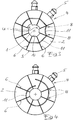
- FIG. 1 eight wedge-shaped press jaw heads 2 are shown arranged around a press axis 1, which are provided with a locking pin 5 on their radial outer surface 4, which forms the contact surface 3 to the assigned base jaw, for their interchangeable attachment to the eight base jaws of the respective radial press.
- the press jaw heads 2 are shown in the configuration that they assume when the press tool is maximally closed, namely in that the respective opposing wedge surfaces 6 of two adjacent press jaw heads bear against one another.
- the pressing jaw heads 2 each have two markings 8 immediately adjacent to the two wedge surfaces 6.
- the markings 8 maintain a matching distance x from the edge 9 at which the relevant wedge surface 6 and the pressing surface 10 of the relevant pressing jaw head 2 abut one another.
- the opposing markings 8 of two identically designed press jaw heads 2 belonging to the same press jaw head set are aligned V. This corresponds to the difference U in the press size radius, but is more noticeable.
- the two markings 8 of each press jaw head 2 adjoining the relevant wedge surfaces are part of a line-shaped marking 11 extending continuously between the two wedge surfaces 6.
- This marking line 11 is designed as a circular arc segment, concentric to the press axis 1.
- the markings 8 (and accordingly the marking lines 11) of the press jaw heads 2 for a larger press diameter have a greater distance a from the press surface 10 than the press jaw heads 2 for a smaller press diameter.
- the offset V of the marking lines 11 of two adjacent press jaw heads 2, which do not belong to the same press jaw head set, is correspondingly larger and more conspicuous than the difference U between the press surfaces 10.
- Fig. 3 illustrates the possibility that the marking lines 11 of the press jaw heads 2, which belong to different press jaw head sets, differ conspicuously from one another in terms of shape.
- the two markings 8 provided on the face of all press jaw heads 2 are in turn part of a line-shaped mark 11 extending continuously from one wedge surface 6 to the other Press jaw heads 2 are not identical, but rather different from one another. Only in the in Fig. 4 The correct arrangement of the eight pressing jaw heads 2 shown here form (with the pressing tool completely closed) the linear markings 11 of the pressing jaw heads 2 together form a continuous marking line extending over all pressing jaw heads 2. In the case of any assembly of the press jaw heads 2 that deviates from the predetermined arrangement, the marking line is interrupted, as is the case in the case of incorrect assembly.
Claims (15)
- Presse radiale avec une structure de base, un outil de presse logé dedans et une unité d'entraînement, sachant que l'outil de presse comprend plusieurs mâchoires de base disposées autour d'un axe de presse (1), lesquelles peuvent être déplacées de façon synchrone radialement au moyen de l'unité d'entraînement sur l'axe de presse de ou vers celui-ci et sur lesquelles peut être respectivement montée de façon interchangeable, une tête à mâchoires de compression (2) pour l'essentiel cunéiforme et sachant en plus que dans un magasin attribué est approvisionnée une pluralité de jeux de têtes à mâchoires de compression adaptés à des diamètres de presse différents, caractérisée en ce que les têtes à mâchoires de compression (2) comportent sur au moins une face avant axiale (7) deux marquages (8) directement adjacents aux deux faces cunéiformes (6), sachant que respectivement les deux marquages (8) mutuellement opposés de deux têtes à mâchoires de compression (2) voisines sont alignés l'un par rapport à l'autre et sachant en plus que pour des jeux de têtes à mâchoires de compression différents, des marquages (8) différents les uns par rapport aux autres sont prévus.
- Presse radiale selon la revendication 1, caractérisée en ce que les marquages (8) des têtes à mâchoires de compression (2) respectivement d'un jeu de têtes à mâchoires de compression sont exécutés de façon identique les uns par rapport aux autres.
- Presse radiale selon la revendication 2, caractérisée en ce que les marquages (8) des différents jeux de têtes à mâchoires de compression se différencient au moins en ce qui concerne leur distance par rapport à la face de contact (3) sur laquelle les têtes à mâchoires de compression (2) viennent s'appliquer aux mâchoires de base.
- Presse radiale selon la revendication 2 ou la revendication 3, caractérisée en ce que les deux marquages (8) de chaque tête à mâchoires de compression font respectivement partie d'un marquage (11) linéaire s'étendant au moins pour l'essentiel entre les deux faces cunéiformes (6).
- Presse radiale selon la revendication 4, caractérisée en ce que les marquages linéaires (11) s'étendent respectivement en continu d'une face cunéiforme (6) à l'autre de telle sorte qu'avec un outil de presse complètement fermé, une ligne de marquage totalement fermée est visible de façon frontale.
- Presse radiale selon la revendication 4 ou la revendication 5, caractérisée en ce que les marquages linéaires (11) comprennent des cavités rainurées aménagées dans la face avant (7) concernée de la tête à mâchoires de compression (2) respective.
- Presse radiale selon la revendication 4 ou la revendication 5, caractérisée en ce que les marquages linéaires (11) comprennent des nervures saillantes disposées sur la face avant concernée (7) de la tête à mâchoires de compression (2) respective.
- Presse radiale selon l'une quelconque des revendications 4 à 7, caractérisée en ce que les marquages linéaires (11) sont exécutés pour l'essentiel sous la forme de segments d'arc de cercle.
- Presse radiale selon l'une quelconque des revendications 2 à 8, caractérisée en ce que les marquages (8) des jeux de têtes à mâchoires de compression individuels comportent respectivement pour l'essentiel la même distance (x) par rapport à la face de compression (10).
- Presse radiale selon l'une quelconque des revendications 2 à 8, caractérisée en ce que les marquages (8) des têtes à mâchoires de compression (2) comportent pour un diamètre de compression plus grand une distance plus grande (a) par rapport à la surface de compression (10) que les têtes à mâchoires de compression (2) pour un diamètre de compression plus faible.
- Presse radiale selon la revendication 1, caractérisée en ce que les marquages (8) des têtes à mâchoires de compression (2) respectivement d'un jeu de têtes à mâchoires de compression sont exécutés de façon différente les uns par rapport aux autres.
- Presse radiale selon la revendication 11, caractérisée en ce que les deux marquages (8) de chaque tête à mâchoires de compression (2) font respectivement partie d'un marquage linéaire (11) s'étendant en continu d'une face cunéiforme (6) à une autre de telle sorte qu'avec un outil de presse complètement fermé une ligne de marquage s'étendant sur toutes les têtes à mâchoires de compression (2) est visible de façon frontale.
- Presse radiale selon l'une quelconque des revendications 1 à 9, caractérisée en ce que les têtes à mâchoires de compression (2) comportent sur les deux faces avant axiales (7), deux marquages (8) directement adjacents aux deux faces cunéiformes (6), sachant que les deux marquages (8) mutuellement opposés de deux têtes à mâchoires de compression (2) voisines sont respectivement alignés sur chacune des deux faces avant.
- Presse radiale selon la revendication 11, caractérisée en ce que les marquages (8) des têtes à mâchoires de compression sont respectivement exécutés de façon différente sur les deux faces avant.
- Presse radiale selon l'une quelconque des revendications 1 à 14, caractérisée en ce que les marquages (8) des jeux de têtes à mâchoires de compression individuels se différencient les uns des autres par la couleur.
Priority Applications (1)
| Application Number | Priority Date | Filing Date | Title |
|---|---|---|---|
| PL16708651T PL3277447T3 (pl) | 2015-04-02 | 2016-03-07 | Prasa promieniowa |
Applications Claiming Priority (2)
| Application Number | Priority Date | Filing Date | Title |
|---|---|---|---|
| DE102015004440.0A DE102015004440B3 (de) | 2015-04-02 | 2015-04-02 | Radialpresse |
| PCT/EP2016/054798 WO2016155981A1 (fr) | 2015-04-02 | 2016-03-07 | Presse radiale |
Publications (2)
| Publication Number | Publication Date |
|---|---|
| EP3277447A1 EP3277447A1 (fr) | 2018-02-07 |
| EP3277447B1 true EP3277447B1 (fr) | 2021-10-20 |
Family
ID=55486110
Family Applications (1)
| Application Number | Title | Priority Date | Filing Date |
|---|---|---|---|
| EP16708651.1A Active EP3277447B1 (fr) | 2015-04-02 | 2016-03-07 | Presse radiale |
Country Status (5)
| Country | Link |
|---|---|
| US (1) | US10105743B2 (fr) |
| EP (1) | EP3277447B1 (fr) |
| DE (1) | DE102015004440B3 (fr) |
| PL (1) | PL3277447T3 (fr) |
| WO (1) | WO2016155981A1 (fr) |
Families Citing this family (2)
| Publication number | Priority date | Publication date | Assignee | Title |
|---|---|---|---|---|
| DE102017108399B4 (de) * | 2017-04-20 | 2019-05-16 | Uniflex-Hydraulik Gmbh | Radialpresse |
| EP3656504B1 (fr) * | 2018-11-20 | 2022-02-23 | WEZAG GmbH & Co. KG | Outil de moulage, ensemble d'outil de moulage, réseau d'outils de moulage et procédé de moulage d'une pièce à usiner |
Family Cites Families (10)
| Publication number | Priority date | Publication date | Assignee | Title |
|---|---|---|---|---|
| AU411164B2 (en) * | 1968-02-19 | 1971-02-26 | RUSSELL DUFFIELD and CLAUDE HARCOURT HARVEY FREDERICK | Improved crimping or compression device |
| US3750452A (en) * | 1971-10-07 | 1973-08-07 | Weatherhead Co | Collet crimper |
| FI772651A (fi) * | 1977-09-07 | 1979-03-08 | Lillbackan Konepaja | Maskin foer fastpressning av kopplingsstycken foer slangar |
| US6257042B1 (en) * | 1999-11-05 | 2001-07-10 | Lillbacka Oy | Open throat crimping machine |
| DE20017791U1 (de) * | 2000-10-17 | 2000-12-28 | Uniflex Hydraulik Gmbh | Preßbackensatz für eine Radialpresse |
| US6845645B2 (en) * | 2001-04-06 | 2005-01-25 | Michael A. Bartrom | Swaging feedback control method and apparatus |
| DE20109212U1 (de) * | 2001-04-23 | 2002-09-12 | Uniflex Hydraulik Gmbh | Vorrichtung zum Einsetzen bzw. Entnehmen eines Wechselbackensatzes in das bzw. aus dem Werkzeug einer Radialpresse |
| ITBS20030034A1 (it) * | 2003-04-04 | 2004-10-05 | Op Srl | Pinza portautensili perfezionata per presse radiali. |
| US7797979B2 (en) * | 2006-02-14 | 2010-09-21 | Eaton Corporation | Crimping apparatus including a tool for supporting a plurality of crimping members |
| US8230714B2 (en) * | 2009-01-23 | 2012-07-31 | Custom Machining Services, Inc. | Die carrier assembly and crimping process |
-
2015
- 2015-04-02 DE DE102015004440.0A patent/DE102015004440B3/de not_active Expired - Fee Related
-
2016
- 2016-03-07 EP EP16708651.1A patent/EP3277447B1/fr active Active
- 2016-03-07 WO PCT/EP2016/054798 patent/WO2016155981A1/fr active Application Filing
- 2016-03-07 PL PL16708651T patent/PL3277447T3/pl unknown
-
2017
- 2017-09-26 US US15/715,713 patent/US10105743B2/en active Active
Also Published As
| Publication number | Publication date |
|---|---|
| WO2016155981A1 (fr) | 2016-10-06 |
| DE102015004440B3 (de) | 2016-03-31 |
| US20180015523A1 (en) | 2018-01-18 |
| US10105743B2 (en) | 2018-10-23 |
| EP3277447A1 (fr) | 2018-02-07 |
| PL3277447T3 (pl) | 2022-02-07 |
Similar Documents
| Publication | Publication Date | Title |
|---|---|---|
| EP2425917B1 (fr) | Mandrin à diaphragme | |
| WO2011101397A1 (fr) | Combinaison de clés pour armoire de distribution | |
| EP3463724A1 (fr) | Plaquette de coupe et outil d'usinage par enlèvement de copeaux | |
| DE2744410A1 (de) | 4-backen-spannfutter fuer ein werkstueck | |
| EP3277447B1 (fr) | Presse radiale | |
| EP3110587B1 (fr) | Système de fixation destiné à une panne | |
| DE10057977A1 (de) | Spannfutter | |
| DE2520920A1 (de) | Herausnehmbare schutzvorrichtung an zylindern von druckmaschinen | |
| DE3320693A1 (de) | Werkzeughalter fuer werkzeugmaschinen | |
| EP0873816A2 (fr) | Cylindre pour positionnement et serrage rapide | |
| DE3137878C2 (de) | Überlastsicherung für den Vorschubantrieb an einer Werkzeugmaschine | |
| DE102016109452A1 (de) | Schneidplatte für ein Fräswerkzeug und Fräswerkzeug | |
| EP3845343B1 (fr) | Pied magnétique | |
| DE102006005880A1 (de) | Schneidwerkzeug für spanende Bearbeitung | |
| DE202015002557U1 (de) | Radialpresse | |
| DE102005049666B4 (de) | Wälzlager | |
| DE102019111843A1 (de) | Zerspanungswerkzeug | |
| EP1442832B1 (fr) | Dispositif de serrage pour serrer un boulon d'ancrage d'alimentation latèral des boules de serrage | |
| DE202006008622U1 (de) | Schrauben-Markierungssystem | |
| DE4446402A1 (de) | Verfahren zur Bildung eines Gewindes in einer Hülse, die zum Halten eines Schlauches dient | |
| DE102017120327A1 (de) | Pressmatrize für ein Presswerkzeug zum Verpressen von rundrohrförmigen Werkstückabschnitten, Presswerkzeug, Verfahren zur Herstellung einer Pressverbindung sowie Verfahren zur Herstellung einer Pressmatrize | |
| DE102010005580A1 (de) | Schneidwerkzeug mit kegelstumpfförmigen Schneidelementen | |
| DE19806617A1 (de) | Ausbeulvorrichtung und Bearbeitungsteil für Ausbeulvorrichtung | |
| EP3103594B1 (fr) | Coffret d'outil | |
| EP4279024A1 (fr) | Pilier dentaire et aide au positionnement pour piliers dentaires |
Legal Events
| Date | Code | Title | Description |
|---|---|---|---|
| STAA | Information on the status of an ep patent application or granted ep patent |
Free format text: STATUS: THE INTERNATIONAL PUBLICATION HAS BEEN MADE |
|
| PUAI | Public reference made under article 153(3) epc to a published international application that has entered the european phase |
Free format text: ORIGINAL CODE: 0009012 |
|
| STAA | Information on the status of an ep patent application or granted ep patent |
Free format text: STATUS: REQUEST FOR EXAMINATION WAS MADE |
|
| 17P | Request for examination filed |
Effective date: 20171005 |
|
| AK | Designated contracting states |
Kind code of ref document: A1 Designated state(s): AL AT BE BG CH CY CZ DE DK EE ES FI FR GB GR HR HU IE IS IT LI LT LU LV MC MK MT NL NO PL PT RO RS SE SI SK SM TR |
|
| AX | Request for extension of the european patent |
Extension state: BA ME |
|
| DAV | Request for validation of the european patent (deleted) | ||
| DAX | Request for extension of the european patent (deleted) | ||
| GRAP | Despatch of communication of intention to grant a patent |
Free format text: ORIGINAL CODE: EPIDOSNIGR1 |
|
| STAA | Information on the status of an ep patent application or granted ep patent |
Free format text: STATUS: GRANT OF PATENT IS INTENDED |
|
| INTG | Intention to grant announced |
Effective date: 20210510 |
|
| GRAS | Grant fee paid |
Free format text: ORIGINAL CODE: EPIDOSNIGR3 |
|
| GRAA | (expected) grant |
Free format text: ORIGINAL CODE: 0009210 |
|
| STAA | Information on the status of an ep patent application or granted ep patent |
Free format text: STATUS: THE PATENT HAS BEEN GRANTED |
|
| AK | Designated contracting states |
Kind code of ref document: B1 Designated state(s): AL AT BE BG CH CY CZ DE DK EE ES FI FR GB GR HR HU IE IS IT LI LT LU LV MC MK MT NL NO PL PT RO RS SE SI SK SM TR |
|
| REG | Reference to a national code |
Ref country code: GB Ref legal event code: FG4D Free format text: NOT ENGLISH |
|
| REG | Reference to a national code |
Ref country code: CH Ref legal event code: EP |
|
| REG | Reference to a national code |
Ref country code: DE Ref legal event code: R096 Ref document number: 502016014011 Country of ref document: DE |
|
| REG | Reference to a national code |
Ref country code: IE Ref legal event code: FG4D Free format text: LANGUAGE OF EP DOCUMENT: GERMAN |
|
| REG | Reference to a national code |
Ref country code: AT Ref legal event code: REF Ref document number: 1439497 Country of ref document: AT Kind code of ref document: T Effective date: 20211115 |
|
| REG | Reference to a national code |
Ref country code: FI Ref legal event code: FGE |
|
| REG | Reference to a national code |
Ref country code: LT Ref legal event code: MG9D |
|
| REG | Reference to a national code |
Ref country code: NL Ref legal event code: MP Effective date: 20211020 |
|
| PG25 | Lapsed in a contracting state [announced via postgrant information from national office to epo] |
Ref country code: RS Free format text: LAPSE BECAUSE OF FAILURE TO SUBMIT A TRANSLATION OF THE DESCRIPTION OR TO PAY THE FEE WITHIN THE PRESCRIBED TIME-LIMIT Effective date: 20211020 Ref country code: LT Free format text: LAPSE BECAUSE OF FAILURE TO SUBMIT A TRANSLATION OF THE DESCRIPTION OR TO PAY THE FEE WITHIN THE PRESCRIBED TIME-LIMIT Effective date: 20211020 Ref country code: BG Free format text: LAPSE BECAUSE OF FAILURE TO SUBMIT A TRANSLATION OF THE DESCRIPTION OR TO PAY THE FEE WITHIN THE PRESCRIBED TIME-LIMIT Effective date: 20220120 |
|
| PG25 | Lapsed in a contracting state [announced via postgrant information from national office to epo] |
Ref country code: IS Free format text: LAPSE BECAUSE OF FAILURE TO SUBMIT A TRANSLATION OF THE DESCRIPTION OR TO PAY THE FEE WITHIN THE PRESCRIBED TIME-LIMIT Effective date: 20220220 Ref country code: SE Free format text: LAPSE BECAUSE OF FAILURE TO SUBMIT A TRANSLATION OF THE DESCRIPTION OR TO PAY THE FEE WITHIN THE PRESCRIBED TIME-LIMIT Effective date: 20211020 Ref country code: PT Free format text: LAPSE BECAUSE OF FAILURE TO SUBMIT A TRANSLATION OF THE DESCRIPTION OR TO PAY THE FEE WITHIN THE PRESCRIBED TIME-LIMIT Effective date: 20220221 Ref country code: NO Free format text: LAPSE BECAUSE OF FAILURE TO SUBMIT A TRANSLATION OF THE DESCRIPTION OR TO PAY THE FEE WITHIN THE PRESCRIBED TIME-LIMIT Effective date: 20220120 Ref country code: NL Free format text: LAPSE BECAUSE OF FAILURE TO SUBMIT A TRANSLATION OF THE DESCRIPTION OR TO PAY THE FEE WITHIN THE PRESCRIBED TIME-LIMIT Effective date: 20211020 Ref country code: LV Free format text: LAPSE BECAUSE OF FAILURE TO SUBMIT A TRANSLATION OF THE DESCRIPTION OR TO PAY THE FEE WITHIN THE PRESCRIBED TIME-LIMIT Effective date: 20211020 Ref country code: HR Free format text: LAPSE BECAUSE OF FAILURE TO SUBMIT A TRANSLATION OF THE DESCRIPTION OR TO PAY THE FEE WITHIN THE PRESCRIBED TIME-LIMIT Effective date: 20211020 Ref country code: GR Free format text: LAPSE BECAUSE OF FAILURE TO SUBMIT A TRANSLATION OF THE DESCRIPTION OR TO PAY THE FEE WITHIN THE PRESCRIBED TIME-LIMIT Effective date: 20220121 Ref country code: ES Free format text: LAPSE BECAUSE OF FAILURE TO SUBMIT A TRANSLATION OF THE DESCRIPTION OR TO PAY THE FEE WITHIN THE PRESCRIBED TIME-LIMIT Effective date: 20211020 |
|
| REG | Reference to a national code |
Ref country code: DE Ref legal event code: R097 Ref document number: 502016014011 Country of ref document: DE |
|
| PG25 | Lapsed in a contracting state [announced via postgrant information from national office to epo] |
Ref country code: SM Free format text: LAPSE BECAUSE OF FAILURE TO SUBMIT A TRANSLATION OF THE DESCRIPTION OR TO PAY THE FEE WITHIN THE PRESCRIBED TIME-LIMIT Effective date: 20211020 Ref country code: SK Free format text: LAPSE BECAUSE OF FAILURE TO SUBMIT A TRANSLATION OF THE DESCRIPTION OR TO PAY THE FEE WITHIN THE PRESCRIBED TIME-LIMIT Effective date: 20211020 Ref country code: RO Free format text: LAPSE BECAUSE OF FAILURE TO SUBMIT A TRANSLATION OF THE DESCRIPTION OR TO PAY THE FEE WITHIN THE PRESCRIBED TIME-LIMIT Effective date: 20211020 Ref country code: EE Free format text: LAPSE BECAUSE OF FAILURE TO SUBMIT A TRANSLATION OF THE DESCRIPTION OR TO PAY THE FEE WITHIN THE PRESCRIBED TIME-LIMIT Effective date: 20211020 Ref country code: DK Free format text: LAPSE BECAUSE OF FAILURE TO SUBMIT A TRANSLATION OF THE DESCRIPTION OR TO PAY THE FEE WITHIN THE PRESCRIBED TIME-LIMIT Effective date: 20211020 |
|
| PLBE | No opposition filed within time limit |
Free format text: ORIGINAL CODE: 0009261 |
|
| STAA | Information on the status of an ep patent application or granted ep patent |
Free format text: STATUS: NO OPPOSITION FILED WITHIN TIME LIMIT |
|
| 26N | No opposition filed |
Effective date: 20220721 |
|
| PG25 | Lapsed in a contracting state [announced via postgrant information from national office to epo] |
Ref country code: MC Free format text: LAPSE BECAUSE OF FAILURE TO SUBMIT A TRANSLATION OF THE DESCRIPTION OR TO PAY THE FEE WITHIN THE PRESCRIBED TIME-LIMIT Effective date: 20211020 Ref country code: CZ Free format text: LAPSE BECAUSE OF NON-PAYMENT OF DUE FEES Effective date: 20220307 Ref country code: AL Free format text: LAPSE BECAUSE OF FAILURE TO SUBMIT A TRANSLATION OF THE DESCRIPTION OR TO PAY THE FEE WITHIN THE PRESCRIBED TIME-LIMIT Effective date: 20211020 |
|
| REG | Reference to a national code |
Ref country code: CH Ref legal event code: PL |
|
| PG25 | Lapsed in a contracting state [announced via postgrant information from national office to epo] |
Ref country code: SI Free format text: LAPSE BECAUSE OF FAILURE TO SUBMIT A TRANSLATION OF THE DESCRIPTION OR TO PAY THE FEE WITHIN THE PRESCRIBED TIME-LIMIT Effective date: 20211020 |
|
| REG | Reference to a national code |
Ref country code: BE Ref legal event code: MM Effective date: 20220331 |
|
| PG25 | Lapsed in a contracting state [announced via postgrant information from national office to epo] |
Ref country code: LU Free format text: LAPSE BECAUSE OF NON-PAYMENT OF DUE FEES Effective date: 20220307 Ref country code: LI Free format text: LAPSE BECAUSE OF NON-PAYMENT OF DUE FEES Effective date: 20220331 Ref country code: IE Free format text: LAPSE BECAUSE OF NON-PAYMENT OF DUE FEES Effective date: 20220307 Ref country code: CH Free format text: LAPSE BECAUSE OF NON-PAYMENT OF DUE FEES Effective date: 20220331 |
|
| PG25 | Lapsed in a contracting state [announced via postgrant information from national office to epo] |
Ref country code: BE Free format text: LAPSE BECAUSE OF NON-PAYMENT OF DUE FEES Effective date: 20220331 |
|
| PGFP | Annual fee paid to national office [announced via postgrant information from national office to epo] |
Ref country code: FR Payment date: 20230320 Year of fee payment: 8 Ref country code: FI Payment date: 20230320 Year of fee payment: 8 |
|
| REG | Reference to a national code |
Ref country code: AT Ref legal event code: MM01 Ref document number: 1439497 Country of ref document: AT Kind code of ref document: T Effective date: 20220307 |
|
| PGFP | Annual fee paid to national office [announced via postgrant information from national office to epo] |
Ref country code: GB Payment date: 20230323 Year of fee payment: 8 |
|
| P01 | Opt-out of the competence of the unified patent court (upc) registered |
Effective date: 20230529 |
|
| PG25 | Lapsed in a contracting state [announced via postgrant information from national office to epo] |
Ref country code: AT Free format text: LAPSE BECAUSE OF NON-PAYMENT OF DUE FEES Effective date: 20220307 |
|
| PGFP | Annual fee paid to national office [announced via postgrant information from national office to epo] |
Ref country code: IT Payment date: 20230331 Year of fee payment: 8 Ref country code: DE Payment date: 20230531 Year of fee payment: 8 |
|
| PG25 | Lapsed in a contracting state [announced via postgrant information from national office to epo] |
Ref country code: HU Free format text: LAPSE BECAUSE OF FAILURE TO SUBMIT A TRANSLATION OF THE DESCRIPTION OR TO PAY THE FEE WITHIN THE PRESCRIBED TIME-LIMIT; INVALID AB INITIO Effective date: 20160307 |
|
| PG25 | Lapsed in a contracting state [announced via postgrant information from national office to epo] |
Ref country code: MK Free format text: LAPSE BECAUSE OF FAILURE TO SUBMIT A TRANSLATION OF THE DESCRIPTION OR TO PAY THE FEE WITHIN THE PRESCRIBED TIME-LIMIT Effective date: 20211020 Ref country code: CY Free format text: LAPSE BECAUSE OF FAILURE TO SUBMIT A TRANSLATION OF THE DESCRIPTION OR TO PAY THE FEE WITHIN THE PRESCRIBED TIME-LIMIT Effective date: 20211020 |
|
| PGFP | Annual fee paid to national office [announced via postgrant information from national office to epo] |
Ref country code: FI Payment date: 20240319 Year of fee payment: 9 Ref country code: GB Payment date: 20240322 Year of fee payment: 9 |