EP3277447B1 - Radial press - Google Patents
Radial press Download PDFInfo
- Publication number
- EP3277447B1 EP3277447B1 EP16708651.1A EP16708651A EP3277447B1 EP 3277447 B1 EP3277447 B1 EP 3277447B1 EP 16708651 A EP16708651 A EP 16708651A EP 3277447 B1 EP3277447 B1 EP 3277447B1
- Authority
- EP
- European Patent Office
- Prior art keywords
- press
- markings
- jaw heads
- radial
- heads
- Prior art date
- Legal status (The legal status is an assumption and is not a legal conclusion. Google has not performed a legal analysis and makes no representation as to the accuracy of the status listed.)
- Active
Links
- 238000011161 development Methods 0.000 description 8
- 230000018109 developmental process Effects 0.000 description 8
- 238000009434 installation Methods 0.000 description 4
- 230000003287 optical effect Effects 0.000 description 3
- 238000002788 crimping Methods 0.000 description 2
- TWFZGCMQGLPBSX-UHFFFAOYSA-N carbendazim Chemical compound C1=CC=C2NC(NC(=O)OC)=NC2=C1 TWFZGCMQGLPBSX-UHFFFAOYSA-N 0.000 description 1
- 238000004040 coloring Methods 0.000 description 1
- 238000007689 inspection Methods 0.000 description 1
- 230000000007 visual effect Effects 0.000 description 1
- 238000011179 visual inspection Methods 0.000 description 1
Images

Classifications
-
- B—PERFORMING OPERATIONS; TRANSPORTING
- B21—MECHANICAL METAL-WORKING WITHOUT ESSENTIALLY REMOVING MATERIAL; PUNCHING METAL
- B21D—WORKING OR PROCESSING OF SHEET METAL OR METAL TUBES, RODS OR PROFILES WITHOUT ESSENTIALLY REMOVING MATERIAL; PUNCHING METAL
- B21D37/00—Tools as parts of machines covered by this subclass
- B21D37/02—Die constructions enabling assembly of the die parts in different ways
-
- B—PERFORMING OPERATIONS; TRANSPORTING
- B21—MECHANICAL METAL-WORKING WITHOUT ESSENTIALLY REMOVING MATERIAL; PUNCHING METAL
- B21D—WORKING OR PROCESSING OF SHEET METAL OR METAL TUBES, RODS OR PROFILES WITHOUT ESSENTIALLY REMOVING MATERIAL; PUNCHING METAL
- B21D39/00—Application of procedures in order to connect objects or parts, e.g. coating with sheet metal otherwise than by plating; Tube expanders
- B21D39/04—Application of procedures in order to connect objects or parts, e.g. coating with sheet metal otherwise than by plating; Tube expanders of tubes with tubes; of tubes with rods
- B21D39/046—Connecting tubes to tube-like fittings
-
- B—PERFORMING OPERATIONS; TRANSPORTING
- B21—MECHANICAL METAL-WORKING WITHOUT ESSENTIALLY REMOVING MATERIAL; PUNCHING METAL
- B21D—WORKING OR PROCESSING OF SHEET METAL OR METAL TUBES, RODS OR PROFILES WITHOUT ESSENTIALLY REMOVING MATERIAL; PUNCHING METAL
- B21D39/00—Application of procedures in order to connect objects or parts, e.g. coating with sheet metal otherwise than by plating; Tube expanders
- B21D39/04—Application of procedures in order to connect objects or parts, e.g. coating with sheet metal otherwise than by plating; Tube expanders of tubes with tubes; of tubes with rods
- B21D39/048—Application of procedures in order to connect objects or parts, e.g. coating with sheet metal otherwise than by plating; Tube expanders of tubes with tubes; of tubes with rods using presses for radially crimping tubular elements
-
- B—PERFORMING OPERATIONS; TRANSPORTING
- B21—MECHANICAL METAL-WORKING WITHOUT ESSENTIALLY REMOVING MATERIAL; PUNCHING METAL
- B21D—WORKING OR PROCESSING OF SHEET METAL OR METAL TUBES, RODS OR PROFILES WITHOUT ESSENTIALLY REMOVING MATERIAL; PUNCHING METAL
- B21D41/00—Application of procedures in order to alter the diameter of tube ends
-
- B—PERFORMING OPERATIONS; TRANSPORTING
- B21—MECHANICAL METAL-WORKING WITHOUT ESSENTIALLY REMOVING MATERIAL; PUNCHING METAL
- B21J—FORGING; HAMMERING; PRESSING METAL; RIVETING; FORGE FURNACES
- B21J9/00—Forging presses
- B21J9/02—Special design or construction
- B21J9/06—Swaging presses; Upsetting presses
-
- B—PERFORMING OPERATIONS; TRANSPORTING
- B25—HAND TOOLS; PORTABLE POWER-DRIVEN TOOLS; MANIPULATORS
- B25B—TOOLS OR BENCH DEVICES NOT OTHERWISE PROVIDED FOR, FOR FASTENING, CONNECTING, DISENGAGING OR HOLDING
- B25B27/00—Hand tools, specially adapted for fitting together or separating parts or objects whether or not involving some deformation, not otherwise provided for
- B25B27/02—Hand tools, specially adapted for fitting together or separating parts or objects whether or not involving some deformation, not otherwise provided for for connecting objects by press fit or detaching same
- B25B27/10—Hand tools, specially adapted for fitting together or separating parts or objects whether or not involving some deformation, not otherwise provided for for connecting objects by press fit or detaching same inserting fittings into hoses
-
- B—PERFORMING OPERATIONS; TRANSPORTING
- B30—PRESSES
- B30B—PRESSES IN GENERAL
- B30B15/00—Details of, or accessories for, presses; Auxiliary measures in connection with pressing
- B30B15/02—Dies; Inserts therefor; Mounting thereof; Moulds
-
- B—PERFORMING OPERATIONS; TRANSPORTING
- B30—PRESSES
- B30B—PRESSES IN GENERAL
- B30B7/00—Presses characterised by a particular arrangement of the pressing members
- B30B7/04—Presses characterised by a particular arrangement of the pressing members wherein pressing is effected in different directions simultaneously or in turn
-
- B—PERFORMING OPERATIONS; TRANSPORTING
- B21—MECHANICAL METAL-WORKING WITHOUT ESSENTIALLY REMOVING MATERIAL; PUNCHING METAL
- B21D—WORKING OR PROCESSING OF SHEET METAL OR METAL TUBES, RODS OR PROFILES WITHOUT ESSENTIALLY REMOVING MATERIAL; PUNCHING METAL
- B21D37/00—Tools as parts of machines covered by this subclass
- B21D37/14—Particular arrangements for handling and holding in place complete dies
- B21D37/145—Die storage magazines
Definitions
- the present invention relates to a radial press with a basic structure, a press tool accommodated therein and a drive unit, the press tool comprising several base jaws arranged around a press axis, which can be moved radially towards and away from the press axis synchronously by means of the drive unit and on which a substantially wedge-shaped press jaw head can be attached in an exchangeable manner, and a plurality of press jaw head sets matched to different press diameters is also stored in an assigned magazine.
- Radial presses of the above type such as those used, for example, to establish a fixed connection between a hydraulic hose and a connection fitting arranged at the end, are known in various designs, in particular from the product range of Uniflex Hydraulik GmbH, Karben (Germany).
- the magazine, in which the press jaw head sets matched to different press diameters are stored, is typically accommodated in the frame of the radial press, as is also the case, for example US 6257042 B1 is removable.
- US 4250607 A a revolver magazine is suggested as an alternative.
- the pressing tools typically have eight base jaws and the pressing jaw head sets are comparatively narrow staggered.
- the pressing jaw head sets are comparatively narrow staggered.
- press jaw head set comprising eight press jaw heads contains a press jaw head with undersized or oversized dimensions. Since the press jaw heads hardly differ, this often goes unnoticed.
- the pressing carried out with such a (supposed) "press jaw head set” is faulty and does not meet the requirements placed on it. This can even lead to such incorrect crimps that, when the workpieces in question are used, represent a danger to the environment due to a failure or failure of the workpiece in question.
- the present invention is aimed at providing a generic radial press which is improved with regard to the problems of the prior art discussed above.
- the pressing jaw heads have two markings on at least one axial end face immediately adjacent to both wedge surfaces, the two opposing markings of two adjacent pressing jaw heads being aligned with one another, and with different ones Press jaw head sets different markings are provided.
- the radial press according to the invention is thus characterized by specific markings provided on at least one of the end faces of the press jaw heads, with the arrangement of the markings directly adjacent to the wedge surfaces of the press jaw heads in each case two markings provided on adjacent press jaw heads being aligned opposite one another.
- the markings of the press jaw heads of each press jaw head set are designed to be identical to one another. This applies in particular when the installation position of the individual press jaw heads on the base jaws of the radial press is of no importance, in particular because all the press jaw heads of the relevant press jaw head set are absolutely identical. If, however, this is not the case, then - according to another preferred further development of the invention explained in more detail below - the markings of the individual press jaw heads in each case of a press jaw head set can also be designed differently from one another.
- the markings of the press jaw heads of a press jaw head set are identical to one another, the markings of the different press jaw head sets preferably differ at least in terms of their distance from the (radially outer) contact surface on which the press jaw heads rest on the base jaws.
- the two markings of two adjacent press jaw heads that are opposite one another are aligned, provided that the two press jaw heads in question belong to the same press jaw head set. If, however, the two press jaw heads in question belong to different press jaw head sets, then the two are aligned with one another are not opposite markings, but are (more or less strongly) offset radially from one another.
- the two markings of each press jaw head are each part of a linear marking extending at least substantially between the two wedge surfaces.
- the line-shaped markings each extend continuously from one wedge surface to the other, so that with a completely closed pressing tool, a continuous marking line is visible on the end face in the region of the pressing jaw heads. This increases the conspicuity of incorrectly fitting the base jaws, ie the assembly of a press jaw head that does not match the other press jaw heads, and in this way contributes to a particularly low risk of undetected incorrect fitting of the radial press.
- the continuous marking line has a self-contained shape. If the individual marking lines of the press jaw heads are essentially designed as circular arc segments, the resulting closed marking line of the entire press jaw head set can be circular.
- Other particularly suitable closed marking lines are regular polygons, for example octagons.
- the marking lines can also differ in particular with regard to the shape.
- the marking lines can be curved radially outwards in an arc shape, straight and curved in an arc shape radially inwards.
- a press jaw head that does not belong to the other press jaw heads is immediately noticeable due to the shape of its marking line. It would even be harmless if the shape of the marking line was repeated for every third set of press jaw heads; because in such a case the incorrectly equipped press jaw head would attract attention due to its dimensioning which differs significantly from the other press jaw heads.
- the line-shaped markings comprise groove-shaped depressions machined into the respective end face of the respective press jaw head or raised webs arranged on the respective end face of the respective press jaw head. This not only increases the visual perceptibility of a possible incorrect assembly. Rather, it can (additionally) also be felt. This helps the reliability of the control of the correct loading of the radial press.
- the markings of the individual press jaw head sets each have essentially the same distance from the press surface.
- the markings thus directly reflect the crimping diameter to which the individual crimping jaw heads are matched.
- the markings of the pressing jaw heads for a larger pressing diameter can have a greater distance from the pressing surface than the pressing jaw heads for a smaller pressing diameter. This makes it particularly clear - in the event of a faulty assembly - that the markings are offset to one another, so to speak, that one of the press jaw heads does not match the others.
- the color of the markings on the individual press jaw head sets can also differ from one another in terms of color, also in the interest of a particularly high level of conspicuity in the event of a faulty assembly.
- the markings of the individual press jaw heads in each case of a press jaw head set can also be designed differently from one another.
- This development is advantageously used when the installation position of the individual press jaw heads on the base jaws of the radial press is important, in particular because the press jaw heads of the relevant press jaw head set are not absolutely identical. This applies, for example, if the individual press jaw heads of the relevant press jaw head set have a specific cut so that the entirety of the press surfaces (when the radial press is closed) does not define an ideal circular cylinder.
- the two markings of each press jaw head can each be part of a line-shaped mark extending continuously from one wedge surface to the other, so that a marking line extending over all press jaw heads is visible at the end when the press tool is completely closed.
- the relevant continuous marking line - visible when the pressing tool is completely closed - can have the shape of a spiral, for example.
- a conspicuous deviation of the marking from its intended shape, ie a continuous marking line results in this case both in the case of an incorrect fitting of the press jaw head set with a press jaw head that does not belong to this, as well as in the case of a differing from the predetermined arrangement of the individual press jaw heads of the press jaw head set Arrangement.
- the press jaw heads can have two markings on both axial end faces immediately adjacent to both wedge surfaces - within the meaning of the present invention set out above - with the two opposing markings of two adjacent press jaw heads on each of the two end faces align with each other. If the press jaw heads are designed asymmetrically so that they can be attached to the base jaws in two different installation positions, the markings of the press jaw heads are particularly preferably designed differently on the two end faces. In this way it can easily be detected by optical control if one of the press jaw heads is mounted in a different installation position than the other press jaw heads.
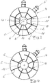
- FIG. 1 eight wedge-shaped press jaw heads 2 are shown arranged around a press axis 1, which are provided with a locking pin 5 on their radial outer surface 4, which forms the contact surface 3 to the assigned base jaw, for their interchangeable attachment to the eight base jaws of the respective radial press.
- the press jaw heads 2 are shown in the configuration that they assume when the press tool is maximally closed, namely in that the respective opposing wedge surfaces 6 of two adjacent press jaw heads bear against one another.
- the pressing jaw heads 2 each have two markings 8 immediately adjacent to the two wedge surfaces 6.
- the markings 8 maintain a matching distance x from the edge 9 at which the relevant wedge surface 6 and the pressing surface 10 of the relevant pressing jaw head 2 abut one another.
- the opposing markings 8 of two identically designed press jaw heads 2 belonging to the same press jaw head set are aligned V. This corresponds to the difference U in the press size radius, but is more noticeable.
- the two markings 8 of each press jaw head 2 adjoining the relevant wedge surfaces are part of a line-shaped marking 11 extending continuously between the two wedge surfaces 6.
- This marking line 11 is designed as a circular arc segment, concentric to the press axis 1.
- the markings 8 (and accordingly the marking lines 11) of the press jaw heads 2 for a larger press diameter have a greater distance a from the press surface 10 than the press jaw heads 2 for a smaller press diameter.
- the offset V of the marking lines 11 of two adjacent press jaw heads 2, which do not belong to the same press jaw head set, is correspondingly larger and more conspicuous than the difference U between the press surfaces 10.
- Fig. 3 illustrates the possibility that the marking lines 11 of the press jaw heads 2, which belong to different press jaw head sets, differ conspicuously from one another in terms of shape.
- the two markings 8 provided on the face of all press jaw heads 2 are in turn part of a line-shaped mark 11 extending continuously from one wedge surface 6 to the other Press jaw heads 2 are not identical, but rather different from one another. Only in the in Fig. 4 The correct arrangement of the eight pressing jaw heads 2 shown here form (with the pressing tool completely closed) the linear markings 11 of the pressing jaw heads 2 together form a continuous marking line extending over all pressing jaw heads 2. In the case of any assembly of the press jaw heads 2 that deviates from the predetermined arrangement, the marking line is interrupted, as is the case in the case of incorrect assembly.
Landscapes
- Engineering & Computer Science (AREA)
- Mechanical Engineering (AREA)
- Shaping Metal By Deep-Drawing, Or The Like (AREA)
- Automatic Assembly (AREA)
- Press Drives And Press Lines (AREA)
Description
Die vorliegende Erfindung betrifft eine Radialpresse mit einer Grundstruktur, einem darin aufgenommenen Presswerkzeug und einer Antriebseinheit, wobei das Presswerkzeug mehrere um eine Pressenachse herum angeordnete Grundbacken umfasst, welche mittels der Antriebseinheit synchron radial auf die Pressenachse zu bzw. von dieser weg bewegbar sind und an denen jeweils ein im Wesentlichen keilförmiger Pressbackenkopf auswechselbar anbringbar ist, und wobei weiterhin in einem zugeordneten Magazin eine Mehrzahl von auf unterschiedliche Pressdurchmesser abgestimmten Pressbackenkopfsätzen bevorratet ist.The present invention relates to a radial press with a basic structure, a press tool accommodated therein and a drive unit, the press tool comprising several base jaws arranged around a press axis, which can be moved radially towards and away from the press axis synchronously by means of the drive unit and on which a substantially wedge-shaped press jaw head can be attached in an exchangeable manner, and a plurality of press jaw head sets matched to different press diameters is also stored in an assigned magazine.
Radialpressen der vorstehenden Art, wie sie beispielsweise der Herstellung einer festen Verbindung zwischen einem Hydraulikschlauch und einer endseitig an diesem angeordneten Anschlussarmatur dienen, sind in diversen Ausführungen bekannt, insbesondere aus dem Produktprogramm der Uniflex Hydraulik GmbH, Karben (Deutschland). Dabei ist typischerweise das Magazin, in welchem die auf unterschiedliche Pressdurchmesser abgestimmten Pressbackenkopfsätze bevorratet sind, in dem Rahmen der Radialpresse untergebracht, so wie dies beispielsweise auch der
Im Hinblick auf gute Ergebnisse der Radialpressung weisen die Presswerkzeuge typischerweise acht Grundbacken auf und sind die Pressbackenkopfsätze vergleichsweise eng gestaffelt. D.h., es sind an der Radialpresse entsprechend viele in dem Magazin zu bevorratende Pressbackenkopfsätze mit (typischerweise acht) sich untereinander jeweils nur geringfügig unterscheidenden Pressbackenköpfen vorhanden.With regard to good results of the radial pressing, the pressing tools typically have eight base jaws and the pressing jaw head sets are comparatively narrow staggered. In other words, there are correspondingly many sets of press jaw heads to be stored in the magazine with (typically eight) press jaw heads that differ from one another only slightly.
Zum Wechsel der vollständigen Pressbackenkopfsätze, um die Radialpresse von einem Pressdurchmesser auf einen anderen umzurüsten, dienen üblicherweise Spezialwerkzeuge, beispielsweise gemäß der
Dies führt zu der potentiellen Gefahr, dass sehr ähnliche Pressbackenköpfe versehentlich vertauscht werden, indem beispielsweise ein acht Pressbackenköpfe umfassender Pressbackenkopfsatz einen Pressbackenkopf mit Unter- oder Übermaß enthält. Da sich die Pressbackenköpfe kaum unterscheiden, bleibt dies häufig unbemerkt. Die mit einem solchen (vermeintlichen) "Pressbackenkopfsatz" ausgeführte Pressung aber ist fehlerhaft und erfüllt nicht die an sie gestellten Anforderungen. Das kann sogar zu solchen Fehlpressungen führen, die, wenn die betreffenden Werkstücke zum Einsatz kommen, wegen eines Ausfalls bzw. Versagens des betreffenden Werkstücks eine Gefahr für die Umgebung darstellen.This leads to the potential danger that very similar press jaw heads are accidentally mixed up, for example in that a press jaw head set comprising eight press jaw heads contains a press jaw head with undersized or oversized dimensions. Since the press jaw heads hardly differ, this often goes unnoticed. The pressing carried out with such a (supposed) "press jaw head set", however, is faulty and does not meet the requirements placed on it. This can even lead to such incorrect crimps that, when the workpieces in question are used, represent a danger to the environment due to a failure or failure of the workpiece in question.
Es ist vorgeschlagen worden (vgl.
Die vorliegende Erfindung ist darauf gerichtet, eine gattungsgemäße Radialpresse bereitzustellen, die im Hinblick auf die vorstehend erörterte Problematik des Standes der Technik verbessert ist.The present invention is aimed at providing a generic radial press which is improved with regard to the problems of the prior art discussed above.
Gelöst wird diese Aufgabenstellung gemäß der vorliegenden Erfindung, indem bei einer Radialpresse der gattungsgemäßen Art die Pressbackenköpfe an mindestens einer axialen Stirnseite unmittelbar angrenzend an beiden Keilflächen zwei Markierungen aufweisen, wobei jeweils die beiden einander gegenüberstehenden Markierungen zweier benachbarter Pressbackenköpfe zueinander fluchten, und wobei weiterhin bei verschiedenen Pressbackenkopfsätzen zueinander unterschiedliche Markierungen vorgesehen sind. Die erfindungsgemäße Radialpresse zeichnet sich somit durch spezifische, an jeweils zumindest einer der Stirnseiten der Pressbackenköpfe vorgesehene Markierungen aus, wobei durch die Anordnung der Markierungen unmittelbar angrenzend an die Keilflächen der Pressbackenköpfe jeweils zwei an einander benachbarten Pressbackenköpfen vorgesehene Markierungen einander fluchtend gegenüberstehen. Dies ermöglicht, dass auf dem Wege einer optischen Kontrolle leicht erfasst wird, ob sämtliche an den Grundbacken montierten Pressbackenköpfe zu demselben Pressbackenkopfsatz gehören oder nicht, wobei das Presswerkzeug für diese optische Kontrolle zweckmäßigerweise in die vollständig geschlossene Stellung gebracht wird, in welcher einander benachbarte Pressbackenköpfe aneinander anliegen.This object is achieved according to the present invention in that, in a radial press of the generic type, the pressing jaw heads have two markings on at least one axial end face immediately adjacent to both wedge surfaces, the two opposing markings of two adjacent pressing jaw heads being aligned with one another, and with different ones Press jaw head sets different markings are provided. The radial press according to the invention is thus characterized by specific markings provided on at least one of the end faces of the press jaw heads, with the arrangement of the markings directly adjacent to the wedge surfaces of the press jaw heads in each case two markings provided on adjacent press jaw heads being aligned opposite one another. This makes it possible, by way of an optical control, to easily detect whether all the press jaw heads mounted on the base jaws belong to the same Press jaw head set belong or not, whereby the press tool for this visual inspection is expediently brought into the completely closed position in which adjacent press jaw heads rest against one another.
In bevorzugter Weiterbildung der vorliegenden Erfindung sind die Markierungen der Pressbackenköpfe jeweils eines Pressbackenkopfsatzes untereinander identisch ausgeführt. Dies gilt namentlich dann, wenn die Einbaubaulage der einzelnen Pressbackenköpfe an den Grundbacken der Radialpresse ohne Bedeutung ist, insbesondere weil sämtliche Pressbackenköpfe des betreffenden Pressbackenkopfsatzes absolut identisch sind. Ist dies indessen nicht der Fall, so können - gemäß einer anderen bevorzugten, weiter unten näher erläuterten Weiterbildung der Erfindung - auch die Markierungen der einzelnen Pressbackenköpfe jeweils eines Pressbackenkopfsatzes untereinander unterschiedlich ausgeführt sein.In a preferred development of the present invention, the markings of the press jaw heads of each press jaw head set are designed to be identical to one another. This applies in particular when the installation position of the individual press jaw heads on the base jaws of the radial press is of no importance, in particular because all the press jaw heads of the relevant press jaw head set are absolutely identical. If, however, this is not the case, then - according to another preferred further development of the invention explained in more detail below - the markings of the individual press jaw heads in each case of a press jaw head set can also be designed differently from one another.
Sind die Markierungen der Pressbackenköpfe jeweils eines Pressbackenkopfsatzes untereinander identisch ausgeführt, so unterscheiden sich die Markierungen der verschiedenen Pressbackenkopfsätze bevorzugt zumindest hinsichtlich ihres Abstands zu der (radial äußeren) Kontaktfläche, an der die Pressbackenköpfe an den Grundbacken anliegen. So fluchten - bei der besagten optischen Kontrolle - die beiden jeweils einander gegenüberstehen Markierungen zweier benachbarter Pressbackenköpfe, sofern die betreffenden zwei Pressbackenköpfe zu demselben Pressbackenkopfsatz gehören. Gehören indessen die betreffenden zwei Pressbackenköpfe zu unterschiedlichen Pressbackenkopfsätzen, so fluchten die beiden einander gegenüberstehen Markierungen nicht, sondern sind (mehr oder weniger stark) radial zueinander versetzt. Ein solcher radialer Versatz der Markierungen benachbarter Pressbackenköpfe wird leicht wahrgenommen, so dass die Anbringung eines falschen Pressbackenkopfes, d.h. eines Pressbackenkopfes mit Unter- oder Übermaß gegenüber den anderen Pressbackenköpfen nicht unerkannt bleibt.If the markings of the press jaw heads of a press jaw head set are identical to one another, the markings of the different press jaw head sets preferably differ at least in terms of their distance from the (radially outer) contact surface on which the press jaw heads rest on the base jaws. Thus, in the case of the said optical inspection, the two markings of two adjacent press jaw heads that are opposite one another are aligned, provided that the two press jaw heads in question belong to the same press jaw head set. If, however, the two press jaw heads in question belong to different press jaw head sets, then the two are aligned with one another are not opposite markings, but are (more or less strongly) offset radially from one another. Such a radial offset of the markings of adjacent press jaw heads is easily perceived, so that the attachment of a wrong press jaw head, ie a press jaw head with undersized or oversized dimensions compared to the other press jaw heads, does not go unnoticed.
In bevorzugter Weiterbildung der vorliegenden Erfindung sind die beiden Markierungen jedes Pressbackenkopfes jeweils Teil einer sich zumindest im Wesentlichen zwischen den beiden Keilflächen erstreckenden linienförmigen Markierung. Besonders bevorzugt erstrecken sich die linienförmigen Markierungen jeweils durchgehend von einer Keilfläche zur anderen, so dass bei einem vollständig geschlossenen Presswerkzeug stirnseitig im Bereich der Pressbackenköpfe eine durchgehende Markierungslinie sichtbar ist. Dies erhöht die Auffälligkeit einer Fehlbestückung der Grundbacken, d.h. der Montage eines nicht zu den anderen Pressbackenköpfen passenden Pressbackenkopfes, und trägt auf diese Weise zu einem besonders geringen Risiko einer unerkannten Fehlbestückung der Radialpresse bei. In dem Falle, dass die Markierungen sämtlicher Pressbackenköpfe eines Pressbackenkopfsatzes identisch übereinstimmen (s.o.), hat die durchgehende Markierungslinie eine in sich geschlossene Gestalt. Sind die einzelnen Markierungslinien der Pressbackenköpfe dabei im Wesentlichen als Kreisbogensegmente ausgeführt, kann die sich ergebende geschlossene Markierungslinie des gesamten Pressbackenkopfsatzes kreisförmig sein. Andere besonders geeignete geschlossene Markierungslinien sind regelmäßige Polygone, beispielsweise Achtecke.In a preferred development of the present invention, the two markings of each press jaw head are each part of a linear marking extending at least substantially between the two wedge surfaces. Particularly preferably, the line-shaped markings each extend continuously from one wedge surface to the other, so that with a completely closed pressing tool, a continuous marking line is visible on the end face in the region of the pressing jaw heads. This increases the conspicuity of incorrectly fitting the base jaws, ie the assembly of a press jaw head that does not match the other press jaw heads, and in this way contributes to a particularly low risk of undetected incorrect fitting of the radial press. In the event that the markings of all the press jaw heads of a press jaw head set coincide identically (see above), the continuous marking line has a self-contained shape. If the individual marking lines of the press jaw heads are essentially designed as circular arc segments, the resulting closed marking line of the entire press jaw head set can be circular. Other particularly suitable closed marking lines are regular polygons, for example octagons.
Alternativ oder additiv zu der weiter oben dargelegten unterschiedlichen Anordnung der Markierungen bzw. Markierungslinien der verschiedenen Pressbackenkopfsätze zumindest hinsichtlich ihres Abstands zu der Kontaktfläche, an der die Pressbackenköpfe an den Grundbacken anliegen, können sich die Markierungslinien insbesondere auch hinsichtlich der Formgebung unterscheiden. So können beispielsweise die Markierungslinien radial nach außen bogenförmig gekrümmt, geradlinig und radial nach innen bogenförmig gekrümmt ausgeführt sein. So fällt ein nicht zu den übrigen Pressbackenköpfen gehörender Pressbackenkopf durch die Formgebung seiner Markierungslinie sofort auf. Dabei wäre es sogar unschädlich, wenn sich bei jedem dritten Pressbackenkopfsatz die Formgebung der Markierungslinie wiederholt; denn in einem solchen Fall würde der fehlbestückte Pressbackenkopf durch seine von den anderen Pressbackenköpfen erheblich abweichende Dimensionierung auffallen.As an alternative or in addition to the different arrangement of the markings or marking lines of the various sets of press jaws set out above, at least in terms of their distance from the contact surface on which the press jaw heads rest on the base jaws, the marking lines can also differ in particular with regard to the shape. For example, the marking lines can be curved radially outwards in an arc shape, straight and curved in an arc shape radially inwards. A press jaw head that does not belong to the other press jaw heads is immediately noticeable due to the shape of its marking line. It would even be harmless if the shape of the marking line was repeated for every third set of press jaw heads; because in such a case the incorrectly equipped press jaw head would attract attention due to its dimensioning which differs significantly from the other press jaw heads.
Gemäß einer anderen bevorzugten Weiterbildung der vorliegenden Erfindung umfassen die linienförmigen Markierungen in die betreffende Stirnfläche des jeweiligen Pressbackenkopfes eingearbeitete rillenförmige Vertiefungen oder aber an der betreffenden Stirnfläche des jeweiligen Pressbackenkopfes angeordnete erhabene Stege. Dies erhöht nicht nur die optische Wahrnehmbarkeit einer möglichen Fehlbestückung. Vielmehr lässt sich eine solche (zusätzlich) auch ertasten. Dies kommt der Zuverlässigkeit der Kontrolle auf eine ordnungsgemäße Bestückung der Radialpresse entgegen.According to another preferred development of the present invention, the line-shaped markings comprise groove-shaped depressions machined into the respective end face of the respective press jaw head or raised webs arranged on the respective end face of the respective press jaw head. This not only increases the visual perceptibility of a possible incorrect assembly. Rather, it can (additionally) also be felt. This helps the reliability of the control of the correct loading of the radial press.
Gemäß einer wiederum anderen bevorzugten Weiterbildung der vorliegenden Erfindung weisen, sofern sämtliche Pressbackenköpfe eines Pressbackenkopfsatzes identisch ausgeführt sind, die Markierungen der einzelnen Pressbackenkopfsätze jeweils im Wesentlichen den gleichen Abstand zur Pressfläche auf. Damit reflektieren die Markierungen unmittelbar den Pressdurchmesser, auf den die einzelnen Pressbackenköpfe abgestimmt sind. Im Hinblick auf eine noch bessere Wahrnehmbarkeit einer Fehlbestückung können allerdings, in alternativer bevorzugter Ausgestaltung, die Markierungen der Pressbackenköpfe für einen größeren Pressdurchmesser einen größeren Abstand zur Pressfläche aufweisen als die Pressbackenköpfe für einen geringeren Pressdurchmesser. Damit wird über den - im Falle einer Fehlbestückung - gewissermaßen übersteigerten Versatz der Markierungen zueinander besonders deutlich, dass einer der Pressbackenköpfe nicht zu den anderen passt.According to yet another preferred development of the present invention, provided that all press jaw heads of a press jaw head set are designed identically, the markings of the individual press jaw head sets each have essentially the same distance from the press surface. The markings thus directly reflect the crimping diameter to which the individual crimping jaw heads are matched. With regard to an even better perceptibility of an incorrect assembly, however, in an alternative preferred embodiment, the markings of the pressing jaw heads for a larger pressing diameter can have a greater distance from the pressing surface than the pressing jaw heads for a smaller pressing diameter. This makes it particularly clear - in the event of a faulty assembly - that the markings are offset to one another, so to speak, that one of the press jaw heads does not match the others.
Ebenfalls im Interesse einer besonders großen Auffälligkeit einer Fehlbestückung können sich die Markierungen der einzelnen Pressbackenkopfsätze farblich voneinander unterscheiden.The color of the markings on the individual press jaw head sets can also differ from one another in terms of color, also in the interest of a particularly high level of conspicuity in the event of a faulty assembly.
Weiter oben wurde bereits dargelegt, dass - gemäß einer bevorzugten Weiterbildung der Erfindung - auch die Markierungen der einzelnen Pressbackenköpfe jeweils eines Pressbackenkopfsatzes untereinander unterschiedlich ausgeführt sein können. Diese Weiterbildung kommt vorteilhafterweise zum Einsatz, wenn die Einbaubaulage der einzelnen Pressbackenköpfe an den Grundbacken der Radialpresse von Bedeutung ist, insbesondere weil die Pressbackenköpfe des betreffenden Pressbackenkopfsatzes nicht absolut identisch sind. Dies gilt beispielsweise, wenn die einzelnen Pressbackenköpfe des betreffenden Pressbackenkopfsatzes einen spezifischen Schliff aufweisen, so dass die Gesamtheit der Pressflächen (bei geschlossener Radialpresse) keinen idealen Kreiszylinder definieren.It has already been explained above that - according to a preferred development of the invention - the markings of the individual press jaw heads in each case of a press jaw head set can also be designed differently from one another. This development is advantageously used when the installation position of the individual press jaw heads on the base jaws of the radial press is important, in particular because the press jaw heads of the relevant press jaw head set are not absolutely identical. This applies, for example, if the individual press jaw heads of the relevant press jaw head set have a specific cut so that the entirety of the press surfaces (when the radial press is closed) does not define an ideal circular cylinder.
Auch in diesem Falle können die beiden Markierungen jedes Pressbackenkopfes jeweils Teil einer sich durchgehend von einer Keilfläche zur anderen erstreckenden linienförmigen Markierung sein, so dass bei einem vollständig geschlossenen Presswerkzeug stirnseitig eine sich über alle Pressbackenköpfe erstreckende Markierungslinie sichtbar ist. Die betreffende - bei vollständig geschlossenem Presswerkzeug sichtbare - durchgehende Markierungslinie kann dabei beispielsweise die Gestalt einer Spirale aufweisen. Eine auffällige Abweichung der Markierung von ihrer Sollgestalt, d.h. einer durchgehenden Markierungslinie, ergibt sich in diesem Falle sowohl im Falle einer Fehlbestückung des Pressbackenkopfsatzes mit einem nicht zu diesem gehörenden Pressbackenkopf, als auch im Falle einer von der vorgegebenen Anordnung der einzelnen Pressbackenköpfe des Pressbackenkopfsatzes zueinander abweichenden Anordnung.In this case, too, the two markings of each press jaw head can each be part of a line-shaped mark extending continuously from one wedge surface to the other, so that a marking line extending over all press jaw heads is visible at the end when the press tool is completely closed. The relevant continuous marking line - visible when the pressing tool is completely closed - can have the shape of a spiral, for example. A conspicuous deviation of the marking from its intended shape, ie a continuous marking line, results in this case both in the case of an incorrect fitting of the press jaw head set with a press jaw head that does not belong to this, as well as in the case of a differing from the predetermined arrangement of the individual press jaw heads of the press jaw head set Arrangement.
Schließlich ist zu erwähnen, dass die Pressbackenköpfe an beiden axialen Stirnseiten unmittelbar angrenzend an beiden Keilflächen - im Sinne der vorliegenden, vorstehend dargelegten Erfindung - zwei Markierungen aufweisen können, wobei an jeder der beiden Stirnseiten jeweils die beiden einander gegenüberstehenden Markierungen zweier benachbarter Pressbackenköpfe zueinander fluchten. Sind die Pressbackenköpfe dabei dergestalt asymmetrisch ausgeführt, so dass sie in zwei unterschiedlichen Einbaulagen an den Grundbacken angebracht werden können, so sind besonders bevorzugt die Markierungen der Pressbackenköpfe jeweils an den beiden Stirnseiten unterschiedlich ausgeführt. Auf diese Weise lässt sich durch optische Kontrolle leicht erfassen, wenn einer der Pressbackenköpfe in einer anderen Einbaulage montiert ist als die anderen Pressbackenköpfe.Finally, it should be mentioned that the press jaw heads can have two markings on both axial end faces immediately adjacent to both wedge surfaces - within the meaning of the present invention set out above - with the two opposing markings of two adjacent press jaw heads on each of the two end faces align with each other. If the press jaw heads are designed asymmetrically so that they can be attached to the base jaws in two different installation positions, the markings of the press jaw heads are particularly preferably designed differently on the two end faces. In this way it can easily be detected by optical control if one of the press jaw heads is mounted in a different installation position than the other press jaw heads.
Im Folgenden wird die vorliegende Erfindung anhand mehrerer bevorzugter Ausführungsbeispiele näher erläutert. Dabei zeigt
- Fig. 1
- in stirnseitiger Draufsicht einen Pressbackenkopfsatz nach einer ersten Ausführungsform der Erfindung, fehlbestückt mit einem Pressbackenkopf mit Untermaß,
- Fig. 2
- in stirnseitiger Draufsicht einen Pressbackenkopfsatz nach einer zweiten Ausführungsform der Erfindung, ebenfalls fehlbestückt mit einem Pressbackenkopf mit Untermaß,
- Fig. 3
- in stirnseitiger Draufsicht einen Pressbackenkopfsatz nach einer dritten Ausführungsform der Erfindung, fehlbestückt mit einem Pressbackenkopf mit Untermaß sowie einem Pressbackenkopf mit Übermaß, und
- Fig. 4
- in stirnseitiger Draufsicht einen richtig bestückten Pressbackenkopfsatz nach einer vierten Ausführungsform der Erfindung bei Einhaltung einer vorgegebenen Anordnung der Pressbackenköpfe.
- Fig. 1
- in an end plan view of a press jaw head set according to a first embodiment of the invention, incorrectly fitted with a press jaw head with undersized dimensions,
- Fig. 2
- in a front plan view of a press jaw head set according to a second embodiment of the invention, also incorrectly equipped with a press jaw head with undersized dimensions,
- Fig. 3
- in a front plan view of a press jaw head set according to a third embodiment of the invention, incorrectly equipped with a press jaw head with undersize and a press jaw head with oversize, and
- Fig. 4
- in a front plan view of a correctly equipped press jaw head set according to a fourth embodiment of the invention while maintaining a predetermined arrangement of the press jaw heads.
Nachdem Radialpressen, auf welchen sich die vorliegende Erfindung umsetzen lässt, ihrer Art nach - zumindest den hier maßgeblichen Fachleuten - hinlänglich bekannt sind, beschränkt sich die Veranschaulichung der Ausführungsbeispiele der Erfindung auf den jeweiligen (in den
In
An den gezeigten axialen Stirnflächen 7 weisen die Pressbackenköpfe 2 jeweils unmittelbar angrenzend an die beiden Keilflächen 6 zwei Markierungen 8 auf. Die Markierungen 8 halten dabei einen übereinstimmenden Abstand x zu jener Kante 9 ein, an welcher jeweils die betreffende Keilfläche 6 und die Pressfläche 10 des betreffenden Pressbackenkopfes 2 aneinander stoßen. Auf diese Weise fluchten jeweils die einander gegenüberstehenden Markierungen 8 zweier identisch ausgeführter, zu dem gleichen Pressbackenkopfsatz gehörender Pressbackenköpfe 2. Indessen besteht zwischen den Markierungen 8 zweier Pressbackenköpfe 2, die nicht zu dem gleichen Pressbackenkopfsatz gehören, ein Versatz V. Dieser entspricht Unterschied U im Pressmaßradius, ist aber auffälliger.On the axial end faces 7 shown, the pressing jaw heads 2 each have two
Nach
Bei der in
Ersichtlich ist bei sämtlichen dargelegten und erläuterten Weiterbildungen möglich, jeweils durch verschiedene Farbgebung der Markierungslinien unterschiedlicher Pressbackenköpfe und/oder durch die Ausführung der Markierungslinien als vertiefte Rillen bzw. erhabene Stege eine zusätzliche auffällige Unterscheidbarkeit herbeizuführen.Obviously, in all of the developments presented and explained, it is possible to create an additional, conspicuous distinction through different coloring of the marking lines of different press jaw heads and / or through the execution of the marking lines as recessed grooves or raised webs.
Claims (15)
- A radial press with a base structure, a pressing tool accommodated therein and a drive unit, wherein the pressing tool comprises a plurality of base jaws arranged around a press axis (1), wherein the base jaws can be moved by the drive unit synchronously radially towards or away from the press axis and to each of which a substantially wedge-shaped press-jaw head (2) can be exchangeably attached, and wherein, furthermore, a plurality of sets of press-jaw heads matched to different press diameters is stored in an associated magazine,
characterized in that
the press jaw heads (2) have two markings (8) on at least one axial end face (7) directly adjoining to both wedge faces (6), wherein two oppositely disposed markings (8) of two neighboring press jaw heads (2) are respectively aligned with one another, and wherein, furthermore, different markings (8) are provided for different sets of press-jaw heads. - The radial press according to claim 1, characterized in that the markings (8) of the press-jaw heads (2) of a respective set of press-jaw heads are constructed identically to one another.
- The radial press according to claim 2, characterized in that the markings (8) of the different sets of press-jaw heads differ at least with respect to their distance to the contact face (3), at which the press-jaw heads (2) are in contact with the base jaws.
- The radial press according to claim 2 or claim 3,
characterized in that the two markings (8) of each press-jaw head are respectively part of a line-shaped marking (11) that extends at least substantially between the two wedge faces (6). - The radial press according to claim 4, characterized in that the line-shaped markings (11) respectively extend continuously from one wedge face (6) to the other, so that, when the pressing tool is completely closed a continuously closed marking line is visible on the end face.
- The radial press according to claim 4 or claim 5,
characterized in that the line-shaped markings (11) comprise groove-like depressions machined into the end faces (7) of the respective press-jaw heads (2). - The radial press according to claim 4 or claim 5,
characterized in that the line-shaped markings (11) comprise raised ridges disposed on the end faces (7) of the respective press-jaw heads (2). - The radial press according to any one of the claims 4 to 7, characterized in that the line-shaped markings (11) are constructed substantially as circular-arc segments.
- The radial press according to any one of the claims 2 to 8, characterized in that the markings (8) of the individual sets of press-jaw heads respectively have a substantially similar distance (x) to the press face (10).
- The radial press according to any one of the claims 2 to 8, characterized in that the markings (8) of the press-jaw heads (2) for a larger press diameter have a larger distance (a) to the press face (10) than the markings of the press-jaw heads (2) for a smaller press diameter.
- The radial press according to claim 1, characterized in that the markings (8) of the press-jaw heads (2) of a respective set of press-jaw heads are constructed differently from one another.
- The radial press according to claim 11, characterized in that the markings (8) of each press-jaw head (2) are respectively part of a line-shaped marking (11) extending continuously from one wedge face (6) to the other, so that, when the pressing tool is completely closed a marking line extending on the end face over all press-jaw heads (2) is visible.
- The radial press according to any one of the claims 1 to 9, characterized in that the press-jaw heads (2) have two markings (8) on each of two axial end faces (7) immediately adjacent to both wedge faces (6), wherein the two corresponding markings (8) of neighboring press-jaw heads (2) are respectively aligned with one another on each of the two end faces.
- The radial press according to claim 11, characterized in that the markings (8) of the press-jaw heads are respectively constructed differently at the two end faces.
- The radial press according to any one of the claims 1 to 14, characterized in that the markings (8) of the individual sets of press-jaw heads are distinguished from one another by color.
Priority Applications (1)
| Application Number | Priority Date | Filing Date | Title |
|---|---|---|---|
| PL16708651T PL3277447T3 (en) | 2015-04-02 | 2016-03-07 | Radial press |
Applications Claiming Priority (2)
| Application Number | Priority Date | Filing Date | Title |
|---|---|---|---|
| DE102015004440.0A DE102015004440B3 (en) | 2015-04-02 | 2015-04-02 | radial press |
| PCT/EP2016/054798 WO2016155981A1 (en) | 2015-04-02 | 2016-03-07 | Radial press |
Publications (2)
| Publication Number | Publication Date |
|---|---|
| EP3277447A1 EP3277447A1 (en) | 2018-02-07 |
| EP3277447B1 true EP3277447B1 (en) | 2021-10-20 |
Family
ID=55486110
Family Applications (1)
| Application Number | Title | Priority Date | Filing Date |
|---|---|---|---|
| EP16708651.1A Active EP3277447B1 (en) | 2015-04-02 | 2016-03-07 | Radial press |
Country Status (5)
| Country | Link |
|---|---|
| US (1) | US10105743B2 (en) |
| EP (1) | EP3277447B1 (en) |
| DE (1) | DE102015004440B3 (en) |
| PL (1) | PL3277447T3 (en) |
| WO (1) | WO2016155981A1 (en) |
Families Citing this family (2)
| Publication number | Priority date | Publication date | Assignee | Title |
|---|---|---|---|---|
| DE102017108399B4 (en) * | 2017-04-20 | 2019-05-16 | Uniflex-Hydraulik Gmbh | radial press |
| EP3656504B1 (en) * | 2018-11-20 | 2022-02-23 | WEZAG GmbH & Co. KG | Press tool, press tool set, press tool network and method for crimping a workpiece |
Family Cites Families (10)
| Publication number | Priority date | Publication date | Assignee | Title |
|---|---|---|---|---|
| AU411164B2 (en) * | 1968-02-19 | 1971-02-26 | RUSSELL DUFFIELD and CLAUDE HARCOURT HARVEY FREDERICK | Improved crimping or compression device |
| US3750452A (en) * | 1971-10-07 | 1973-08-07 | Weatherhead Co | Collet crimper |
| FI772651A (en) * | 1977-09-07 | 1979-03-08 | Lillbackan Konepaja | MASKIN FOER FASTPRESSNING AV KOPPLINGSSTYCKEN FOER SLANGAR |
| US6257042B1 (en) * | 1999-11-05 | 2001-07-10 | Lillbacka Oy | Open throat crimping machine |
| DE20017791U1 (en) * | 2000-10-17 | 2000-12-28 | Uniflex-Hydraulik GmbH, 61184 Karben | Press jaw set for a radial press |
| US6845645B2 (en) * | 2001-04-06 | 2005-01-25 | Michael A. Bartrom | Swaging feedback control method and apparatus |
| DE20109212U1 (en) * | 2001-04-23 | 2002-09-12 | Uniflex-Hydraulik GmbH, 61184 Karben | Device for inserting or removing an interchangeable jaw set into or out of the tool of a radial press |
| ITBS20030034A1 (en) * | 2003-04-04 | 2004-10-05 | Op Srl | TOOL HOLDER FORCEPS PERFECT FOR RADIAL PRESSES. |
| US7797979B2 (en) * | 2006-02-14 | 2010-09-21 | Eaton Corporation | Crimping apparatus including a tool for supporting a plurality of crimping members |
| US8230714B2 (en) * | 2009-01-23 | 2012-07-31 | Custom Machining Services, Inc. | Die carrier assembly and crimping process |
-
2015
- 2015-04-02 DE DE102015004440.0A patent/DE102015004440B3/en not_active Expired - Fee Related
-
2016
- 2016-03-07 EP EP16708651.1A patent/EP3277447B1/en active Active
- 2016-03-07 WO PCT/EP2016/054798 patent/WO2016155981A1/en active Application Filing
- 2016-03-07 PL PL16708651T patent/PL3277447T3/en unknown
-
2017
- 2017-09-26 US US15/715,713 patent/US10105743B2/en active Active
Also Published As
| Publication number | Publication date |
|---|---|
| PL3277447T3 (en) | 2022-02-07 |
| WO2016155981A1 (en) | 2016-10-06 |
| US10105743B2 (en) | 2018-10-23 |
| DE102015004440B3 (en) | 2016-03-31 |
| US20180015523A1 (en) | 2018-01-18 |
| EP3277447A1 (en) | 2018-02-07 |
Similar Documents
| Publication | Publication Date | Title |
|---|---|---|
| EP2425917B1 (en) | Diaphragm chuck | |
| WO2017202679A1 (en) | Cutting insert and tool for machining | |
| DE2744410A1 (en) | 4-JAW CHUCK FOR ONE WORKPIECE | |
| EP3277447B1 (en) | Radial press | |
| EP3110587B1 (en) | Soldering tip fastening system | |
| DE2520920A1 (en) | REMOVABLE PROTECTION DEVICE ON CYLINDERS OF PRINTING MACHINES | |
| DE29716104U1 (en) | Clamping device, especially machine vice | |
| DE3320693A1 (en) | TOOL HOLDER FOR MACHINE TOOLS | |
| EP0873816A2 (en) | Cylinder for positioning and quick-action clamping | |
| DE102016109452A1 (en) | Cutting plate for a milling tool and milling tool | |
| DE69009310T2 (en) | Clamping device for the production of nails. | |
| DE102022102048A1 (en) | Tool changing device, set and configuration with at least one such tool changing device | |
| DE202015002557U1 (en) | radial press | |
| DE102005049666B4 (en) | roller bearing | |
| DE102019111843A1 (en) | Cutting tool | |
| EP1442832B1 (en) | Clamping device for clamping a tie bolt supplying locking balls sideways | |
| DE202006008622U1 (en) | Screw-marking system | |
| DE4446402A1 (en) | Method for forming a thread in a sleeve, which is used to hold a hose | |
| DE102017120327A1 (en) | Press die for a pressing tool for pressing tubular workpiece sections, pressing tool, method for producing a press connection and method for producing a press die | |
| EP4279024A1 (en) | Dental blank and positioning aid for dental blanks | |
| DE202021002300U1 (en) | Device for positioning a semi-finished dental product | |
| DE2166935A1 (en) | Multi way valve arrangement - is mounted with adaptor plate on standard mounting plate | |
| DE202014007307U1 (en) | Die holding plate for a tablet press | |
| DE102022110877A1 (en) | Mounting system | |
| DE20203158U1 (en) | Needle board for a needle machine |
Legal Events
| Date | Code | Title | Description |
|---|---|---|---|
| STAA | Information on the status of an ep patent application or granted ep patent |
Free format text: STATUS: THE INTERNATIONAL PUBLICATION HAS BEEN MADE |
|
| PUAI | Public reference made under article 153(3) epc to a published international application that has entered the european phase |
Free format text: ORIGINAL CODE: 0009012 |
|
| STAA | Information on the status of an ep patent application or granted ep patent |
Free format text: STATUS: REQUEST FOR EXAMINATION WAS MADE |
|
| 17P | Request for examination filed |
Effective date: 20171005 |
|
| AK | Designated contracting states |
Kind code of ref document: A1 Designated state(s): AL AT BE BG CH CY CZ DE DK EE ES FI FR GB GR HR HU IE IS IT LI LT LU LV MC MK MT NL NO PL PT RO RS SE SI SK SM TR |
|
| AX | Request for extension of the european patent |
Extension state: BA ME |
|
| DAV | Request for validation of the european patent (deleted) | ||
| DAX | Request for extension of the european patent (deleted) | ||
| GRAP | Despatch of communication of intention to grant a patent |
Free format text: ORIGINAL CODE: EPIDOSNIGR1 |
|
| STAA | Information on the status of an ep patent application or granted ep patent |
Free format text: STATUS: GRANT OF PATENT IS INTENDED |
|
| INTG | Intention to grant announced |
Effective date: 20210510 |
|
| GRAS | Grant fee paid |
Free format text: ORIGINAL CODE: EPIDOSNIGR3 |
|
| GRAA | (expected) grant |
Free format text: ORIGINAL CODE: 0009210 |
|
| STAA | Information on the status of an ep patent application or granted ep patent |
Free format text: STATUS: THE PATENT HAS BEEN GRANTED |
|
| AK | Designated contracting states |
Kind code of ref document: B1 Designated state(s): AL AT BE BG CH CY CZ DE DK EE ES FI FR GB GR HR HU IE IS IT LI LT LU LV MC MK MT NL NO PL PT RO RS SE SI SK SM TR |
|
| REG | Reference to a national code |
Ref country code: GB Ref legal event code: FG4D Free format text: NOT ENGLISH |
|
| REG | Reference to a national code |
Ref country code: CH Ref legal event code: EP |
|
| REG | Reference to a national code |
Ref country code: DE Ref legal event code: R096 Ref document number: 502016014011 Country of ref document: DE |
|
| REG | Reference to a national code |
Ref country code: IE Ref legal event code: FG4D Free format text: LANGUAGE OF EP DOCUMENT: GERMAN |
|
| REG | Reference to a national code |
Ref country code: AT Ref legal event code: REF Ref document number: 1439497 Country of ref document: AT Kind code of ref document: T Effective date: 20211115 |
|
| REG | Reference to a national code |
Ref country code: FI Ref legal event code: FGE |
|
| REG | Reference to a national code |
Ref country code: LT Ref legal event code: MG9D |
|
| REG | Reference to a national code |
Ref country code: NL Ref legal event code: MP Effective date: 20211020 |
|
| PG25 | Lapsed in a contracting state [announced via postgrant information from national office to epo] |
Ref country code: RS Free format text: LAPSE BECAUSE OF FAILURE TO SUBMIT A TRANSLATION OF THE DESCRIPTION OR TO PAY THE FEE WITHIN THE PRESCRIBED TIME-LIMIT Effective date: 20211020 Ref country code: LT Free format text: LAPSE BECAUSE OF FAILURE TO SUBMIT A TRANSLATION OF THE DESCRIPTION OR TO PAY THE FEE WITHIN THE PRESCRIBED TIME-LIMIT Effective date: 20211020 Ref country code: BG Free format text: LAPSE BECAUSE OF FAILURE TO SUBMIT A TRANSLATION OF THE DESCRIPTION OR TO PAY THE FEE WITHIN THE PRESCRIBED TIME-LIMIT Effective date: 20220120 |
|
| PG25 | Lapsed in a contracting state [announced via postgrant information from national office to epo] |
Ref country code: IS Free format text: LAPSE BECAUSE OF FAILURE TO SUBMIT A TRANSLATION OF THE DESCRIPTION OR TO PAY THE FEE WITHIN THE PRESCRIBED TIME-LIMIT Effective date: 20220220 Ref country code: SE Free format text: LAPSE BECAUSE OF FAILURE TO SUBMIT A TRANSLATION OF THE DESCRIPTION OR TO PAY THE FEE WITHIN THE PRESCRIBED TIME-LIMIT Effective date: 20211020 Ref country code: PT Free format text: LAPSE BECAUSE OF FAILURE TO SUBMIT A TRANSLATION OF THE DESCRIPTION OR TO PAY THE FEE WITHIN THE PRESCRIBED TIME-LIMIT Effective date: 20220221 Ref country code: NO Free format text: LAPSE BECAUSE OF FAILURE TO SUBMIT A TRANSLATION OF THE DESCRIPTION OR TO PAY THE FEE WITHIN THE PRESCRIBED TIME-LIMIT Effective date: 20220120 Ref country code: NL Free format text: LAPSE BECAUSE OF FAILURE TO SUBMIT A TRANSLATION OF THE DESCRIPTION OR TO PAY THE FEE WITHIN THE PRESCRIBED TIME-LIMIT Effective date: 20211020 Ref country code: LV Free format text: LAPSE BECAUSE OF FAILURE TO SUBMIT A TRANSLATION OF THE DESCRIPTION OR TO PAY THE FEE WITHIN THE PRESCRIBED TIME-LIMIT Effective date: 20211020 Ref country code: HR Free format text: LAPSE BECAUSE OF FAILURE TO SUBMIT A TRANSLATION OF THE DESCRIPTION OR TO PAY THE FEE WITHIN THE PRESCRIBED TIME-LIMIT Effective date: 20211020 Ref country code: GR Free format text: LAPSE BECAUSE OF FAILURE TO SUBMIT A TRANSLATION OF THE DESCRIPTION OR TO PAY THE FEE WITHIN THE PRESCRIBED TIME-LIMIT Effective date: 20220121 Ref country code: ES Free format text: LAPSE BECAUSE OF FAILURE TO SUBMIT A TRANSLATION OF THE DESCRIPTION OR TO PAY THE FEE WITHIN THE PRESCRIBED TIME-LIMIT Effective date: 20211020 |
|
| REG | Reference to a national code |
Ref country code: DE Ref legal event code: R097 Ref document number: 502016014011 Country of ref document: DE |
|
| PG25 | Lapsed in a contracting state [announced via postgrant information from national office to epo] |
Ref country code: SM Free format text: LAPSE BECAUSE OF FAILURE TO SUBMIT A TRANSLATION OF THE DESCRIPTION OR TO PAY THE FEE WITHIN THE PRESCRIBED TIME-LIMIT Effective date: 20211020 Ref country code: SK Free format text: LAPSE BECAUSE OF FAILURE TO SUBMIT A TRANSLATION OF THE DESCRIPTION OR TO PAY THE FEE WITHIN THE PRESCRIBED TIME-LIMIT Effective date: 20211020 Ref country code: RO Free format text: LAPSE BECAUSE OF FAILURE TO SUBMIT A TRANSLATION OF THE DESCRIPTION OR TO PAY THE FEE WITHIN THE PRESCRIBED TIME-LIMIT Effective date: 20211020 Ref country code: EE Free format text: LAPSE BECAUSE OF FAILURE TO SUBMIT A TRANSLATION OF THE DESCRIPTION OR TO PAY THE FEE WITHIN THE PRESCRIBED TIME-LIMIT Effective date: 20211020 Ref country code: DK Free format text: LAPSE BECAUSE OF FAILURE TO SUBMIT A TRANSLATION OF THE DESCRIPTION OR TO PAY THE FEE WITHIN THE PRESCRIBED TIME-LIMIT Effective date: 20211020 |
|
| PLBE | No opposition filed within time limit |
Free format text: ORIGINAL CODE: 0009261 |
|
| STAA | Information on the status of an ep patent application or granted ep patent |
Free format text: STATUS: NO OPPOSITION FILED WITHIN TIME LIMIT |
|
| 26N | No opposition filed |
Effective date: 20220721 |
|
| PG25 | Lapsed in a contracting state [announced via postgrant information from national office to epo] |
Ref country code: MC Free format text: LAPSE BECAUSE OF FAILURE TO SUBMIT A TRANSLATION OF THE DESCRIPTION OR TO PAY THE FEE WITHIN THE PRESCRIBED TIME-LIMIT Effective date: 20211020 Ref country code: CZ Free format text: LAPSE BECAUSE OF NON-PAYMENT OF DUE FEES Effective date: 20220307 Ref country code: AL Free format text: LAPSE BECAUSE OF FAILURE TO SUBMIT A TRANSLATION OF THE DESCRIPTION OR TO PAY THE FEE WITHIN THE PRESCRIBED TIME-LIMIT Effective date: 20211020 |
|
| REG | Reference to a national code |
Ref country code: CH Ref legal event code: PL |
|
| PG25 | Lapsed in a contracting state [announced via postgrant information from national office to epo] |
Ref country code: SI Free format text: LAPSE BECAUSE OF FAILURE TO SUBMIT A TRANSLATION OF THE DESCRIPTION OR TO PAY THE FEE WITHIN THE PRESCRIBED TIME-LIMIT Effective date: 20211020 |
|
| REG | Reference to a national code |
Ref country code: BE Ref legal event code: MM Effective date: 20220331 |
|
| PG25 | Lapsed in a contracting state [announced via postgrant information from national office to epo] |
Ref country code: LU Free format text: LAPSE BECAUSE OF NON-PAYMENT OF DUE FEES Effective date: 20220307 Ref country code: LI Free format text: LAPSE BECAUSE OF NON-PAYMENT OF DUE FEES Effective date: 20220331 Ref country code: IE Free format text: LAPSE BECAUSE OF NON-PAYMENT OF DUE FEES Effective date: 20220307 Ref country code: CH Free format text: LAPSE BECAUSE OF NON-PAYMENT OF DUE FEES Effective date: 20220331 |
|
| PG25 | Lapsed in a contracting state [announced via postgrant information from national office to epo] |
Ref country code: BE Free format text: LAPSE BECAUSE OF NON-PAYMENT OF DUE FEES Effective date: 20220331 |
|
| REG | Reference to a national code |
Ref country code: AT Ref legal event code: MM01 Ref document number: 1439497 Country of ref document: AT Kind code of ref document: T Effective date: 20220307 |
|
| P01 | Opt-out of the competence of the unified patent court (upc) registered |
Effective date: 20230529 |
|
| PG25 | Lapsed in a contracting state [announced via postgrant information from national office to epo] |
Ref country code: AT Free format text: LAPSE BECAUSE OF NON-PAYMENT OF DUE FEES Effective date: 20220307 |
|
| PG25 | Lapsed in a contracting state [announced via postgrant information from national office to epo] |
Ref country code: HU Free format text: LAPSE BECAUSE OF FAILURE TO SUBMIT A TRANSLATION OF THE DESCRIPTION OR TO PAY THE FEE WITHIN THE PRESCRIBED TIME-LIMIT; INVALID AB INITIO Effective date: 20160307 |
|
| PG25 | Lapsed in a contracting state [announced via postgrant information from national office to epo] |
Ref country code: MK Free format text: LAPSE BECAUSE OF FAILURE TO SUBMIT A TRANSLATION OF THE DESCRIPTION OR TO PAY THE FEE WITHIN THE PRESCRIBED TIME-LIMIT Effective date: 20211020 Ref country code: CY Free format text: LAPSE BECAUSE OF FAILURE TO SUBMIT A TRANSLATION OF THE DESCRIPTION OR TO PAY THE FEE WITHIN THE PRESCRIBED TIME-LIMIT Effective date: 20211020 |
|
| PGFP | Annual fee paid to national office [announced via postgrant information from national office to epo] |
Ref country code: FI Payment date: 20240319 Year of fee payment: 9 Ref country code: GB Payment date: 20240322 Year of fee payment: 9 |
|
| PG25 | Lapsed in a contracting state [announced via postgrant information from national office to epo] |
Ref country code: PL Free format text: LAPSE BECAUSE OF NON-PAYMENT OF DUE FEES Effective date: 20220307 |
|
| PGFP | Annual fee paid to national office [announced via postgrant information from national office to epo] |
Ref country code: IT Payment date: 20240329 Year of fee payment: 9 Ref country code: FR Payment date: 20240320 Year of fee payment: 9 |
|
| PGFP | Annual fee paid to national office [announced via postgrant information from national office to epo] |
Ref country code: DE Payment date: 20240529 Year of fee payment: 9 |