EP3276325A1 - Verbrennungsdrucksensor - Google Patents
Verbrennungsdrucksensor Download PDFInfo
- Publication number
- EP3276325A1 EP3276325A1 EP16768332.5A EP16768332A EP3276325A1 EP 3276325 A1 EP3276325 A1 EP 3276325A1 EP 16768332 A EP16768332 A EP 16768332A EP 3276325 A1 EP3276325 A1 EP 3276325A1
- Authority
- EP
- European Patent Office
- Prior art keywords
- pressure sensor
- pressure
- combustion
- combustion pressure
- injector
- Prior art date
- Legal status (The legal status is an assumption and is not a legal conclusion. Google has not performed a legal analysis and makes no representation as to the accuracy of the status listed.)
- Withdrawn
Links
Images


Classifications
-
- G—PHYSICS
- G01—MEASURING; TESTING
- G01L—MEASURING FORCE, STRESS, TORQUE, WORK, MECHANICAL POWER, MECHANICAL EFFICIENCY, OR FLUID PRESSURE
- G01L23/00—Devices or apparatus for measuring or indicating or recording rapid changes, such as oscillations, in the pressure of steam, gas, or liquid; Indicators for determining work or energy of steam, internal-combustion, or other fluid-pressure engines from the condition of the working fluid
- G01L23/22—Devices or apparatus for measuring or indicating or recording rapid changes, such as oscillations, in the pressure of steam, gas, or liquid; Indicators for determining work or energy of steam, internal-combustion, or other fluid-pressure engines from the condition of the working fluid for detecting or indicating knocks in internal-combustion engines; Units comprising pressure-sensitive members combined with ignitors for firing internal-combustion engines
-
- F—MECHANICAL ENGINEERING; LIGHTING; HEATING; WEAPONS; BLASTING
- F02—COMBUSTION ENGINES; HOT-GAS OR COMBUSTION-PRODUCT ENGINE PLANTS
- F02D—CONTROLLING COMBUSTION ENGINES
- F02D35/00—Controlling engines, dependent on conditions exterior or interior to engines, not otherwise provided for
Definitions
- the present invention relates to a pressure sensor, and more specifically to a combustion pressure sensor that is mounted to a cylinder head of an internal combustion engine and capable of detecting pressure inside a combustion chamber.
- a device using a piezoelectric element for a pressure detection portion has been proposed as a device that is, for example, mounted to a cylinder head of an internal combustion engine to detect pressure inside a combustion chamber.
- a combustion pressure sensor has been known that detects a combustion pressure using this pressure detection device formed in a ring shape and mounted to a functional component, such as an injector or a spark plug, attached to the combustion chamber.
- a spark plug embedded with a pressure sensor as disclosed in, for example, Patent Document 1 has been proposed.
- This spark plug with the pressure sensor is formed by integrally fixing a pressure sensing portion to the spark plug by welding, and the spark plug is tightened and fixed to a cylinder head for use.
- the spark plug is raised by a combustion pressure generated inside a combustion chamber of an internal combustion engine, and this changes the fastening load on the spark plug.
- the pressure sensor detects a charge generated by a piezoelectric element as an electric signal and transmits this signal to a controlling device.
- the controlling device controls the internal combustion engine based on this pressure signal so as to improve fuel consumption for example.
- Patent Document 1 Japanese Patent No. 4620882 ( FIG. 1 and FIG. 2 )
- FIGs. 11A, 11B and 12 are diagrams redrawn for easier explanation of the conventional technique, and the names of the components are changed to conform to the present application without departing from the gist of the invention.
- FIG. 11A illustrates a configuration of a spark plug 300 with a conventional combustion pressure sensor. The figure shows a state before welding.
- FIG. 11B is an enlarged view of the part A in FIG. 11A and shows a state after welding.
- FIG.12 shows a state where the spark plug 300 with the combustion pressure sensor is mounted to the cylinder head.
- FIG. 11A the configuration of the spark plug 300 embedded with the combustion pressure sensor will be explained using FIG. 11A .
- a sensor case 321 that is annular-shaped and composed of a cylindrical portion 321a and a bottom portion 321b
- a pressure sensor 320 is thus constituted.
- a lead wire 327 is extended upward from a terminal 324a that is formed on a part of the annular electrode plate 324.
- the cylindrical portion 321a of the sensor case 321 is fitted to a first bulged portion 311c1 of a main fitting 311, and an engaging portion 321c of the sensor case 321 abuts on a case supporting portion 311s at a front end of a second bulged portion 311c2.
- a welding portion W1 is laser-welded along the entire circumference of the sensor case 321.
- a welding portion W2 is laser-welded along the entire circumference of the sensor case 321.
- the pressure sensor 320 is in a state where the predetermined load P is applied to the piezoelectric element 323 as a result of the welding of the sensor case 321 and the main fitting 311. Moreover, in the pressure sensor 320, a fastening load (hereinafter referred to as an "additional load") is added to the piezoelectric element 323 due to fastening in mounting the spark plug 300 (described later) to the cylinder head. Accordingly, the pressure sensor 320 is configured to detect pressure in a state where a total load of the load P and the fastening load is acting on the piezoelectric element 323 as a preload.
- the welding portion W1 is laser-welded along the entire circumference of the sensor case 321.
- the sensor case 321 and the main fitting 311 may be welded to each other in a state where the sensor case 321 or the main fitting 311 has been deformed by welding heat that is generated during the welding, due to difference in thermal capacity, linear expansion coefficient and the like between the sensor case 321 and the main fitting 311.
- the bottom portion 321b of the sensor case 321 is pushed out downward in the figure due to the welding heat generated during the welding.
- a gap at an angle ⁇ is formed between the bottom portion 321b and the sensor case 321, and in this state the engaging portion 321c abuts on the case supporting portion 311s to be weld-fixed at the welding portion W1 (the welding portion is indicated by a black circle in the figure). If distortion occurs in the sensor 321 or the main fitting 311 due to the welding heat and the like as explained above, it will result in unevenness of the surface pressure on the components stacked inside the sensor case 321 including the piezoelectric element, and it will also cause the load P on the piezoelectric element 323 to differ from the predetermined load set in advance.
- FIG. 12 when mounted to the cylinder head 4, the spark plug 300 embedded with the combustion pressure sensor is fitted with a gasket 311b, and a hexagonal nut portion (not shown) is rotated with a tool to fasten the spark plug 300.
- a deviation (hereinafter referred to as a "hysteresis") occurs between the pressure applied to the pressure sensor 320 and the output waveform of the pressure. This results in a failure to accurately measure the pressure.
- An object of the present invention is to solve the above problem by providing a combustion pressure sensor that is capable of accurately measuring the pressure.
- the present invention prevents a failure in the pressure transmission system of the combustion pressure sensor by providing a means for minimizing distortion of the sensor case of the combustion pressure sensor during weld-joining of the combustion pressure sensor and a functional component.
- the present invention provides a combustion pressure sensor mounted to a functional component attached to a combustion chamber of an internal combustion engine, wherein a pressure receiving member and a pressure detection element are supported by a housing, the pressure receiving member being a pressure receiving surface for receiving a combustion pressure, the pressure detection element detecting a pressure from the pressure receiving surface, the mounting of the combustion pressure sensor to the functional component is performed by joining the functional component and a connecting member provided to at least one of the pressure receiving member and the housing, and the connecting member is composed of a joint portion and a distortion buffer portion, the joint portion being joined with the functional component, the distortion buffer portion reducing influence of distortion occurring in the joint portion on the pressure receiving member or the housing.
- combustion pressure sensor is provided such that the connecting member is integrally formed with the pressure receiving member or the housing.
- combustion pressure sensor is provided such that the connecting member is formed separately from the pressure receiving member or the housing.
- the combustion pressure sensor is provided such that the connecting member has a linear expansion coefficient that is comparable to a material of a joint portion of the functional component.
- combustion pressure sensor is provided such that the joining of the functional component and the connecting member is performed by welding.
- the combustion pressure sensor is provided such that the combustion pressure sensor is cylindrically shaped, the housing is composed of a housing unit and a cylindrical supporting member, the housing unit including an outer cylindrical portion and an inner cylindrical portion respectively constituting an outer surface and an inner surface of the combustion pressure sensor, and the pressure detection element is arranged inside the housing unit, and the pressure receiving member and the supporting member are arranged so as to interpose the pressure detection element.
- the combustion pressure sensor is provided such that the connecting member has a cylindrical shape extending along the inner surface of the inner cylindrical portion
- the connecting member for connecting the combustion pressure sensor and the functional component is provided with a distortion buffer portion that reduces the influence of distortion occurring in the portion to be joined with the combustion pressure sensor. This enables to minimize deformation of the housing or the pressure receiving member of the combustion pressure sensor. Therefore, the present invention provides a combustion pressure sensor that is capable of accurately measuring the pressure.
- the combustion pressure sensor of the present invention is directed to improving a joint between the combustion pressure sensor and a functional component such as an injector.
- a connecting member with a distortion buffer portion is used for joining the combustion pressure sensor and the functional component. This enables the distortion buffer portion to absorb distortion that occurs in the joint portion during joining, and thus enables to minimize deformation of a housing unit (hereinafter referred to as a "case part") of the combustion pressure sensor.
- Example 1 is directed to improving a joint of an injector unit that is formed by mounting the combustion pressure sensor to an injector.
- Example 2 is directed to improving a joint of a spark plug unit that is formed by mounting the combustion pressure sensor to a spark plug.
- Example 1 will be explained using FIGs. 1-9 and Example 2 will be explained using FIG. 10 .
- FIGs. 1-5 illustrate the first exemplary embodiment of Example 1.
- FIGs. 1-3 illustrate a basic configuration of an injector unit and an internal combustion engine to be embedded with the combustion pressure sensor of the present invention
- FIGs. 4-5 illustrate the configuration and the assembly process according to the first exemplary embodiment.
- Example 1 includes other two exemplary embodiments, and the basic configuration shown in FIGs. 1-3 is common to these exemplary embodiments. Features of the configurations of these exemplary embodiments are respectively illustrated in FIGs. 6 and 8 .
- FIG. 1 illustrates a schematic configuration of the internal combustion engine 1.
- FIG. 2 is an enlarged view of the part S in FIG. 1.
- FIG. 1 shows the internal combustion engine 1 in a state where an injector unit 6A is incorporated therein.
- the injector unit 6A is formed by an injector 7A and a combustion pressure sensor 8A of the present invention mounted to the injector 7A.
- the internal combustion engine 1 is composed of: a cylinder block 2 including a cylinder 2a; a piston 3 reciprocating in the cylinder 2a; and a cylinder head 4 that is fastened to the cylinder block 2 to constitute a combustion chamber C with the cylinder 2a, the piston 3 and the like.
- the combustion chamber C is thus formed.
- the internal combustion engine 1 includes: the injector unit 6A that is attached to the cylinder head 4 and injects fuel into the combustion chamber C; and a spark plug 5 (shown by the dashed line in the figure) that is attached to the cylinder head 4 and ignites the air-fuel mixture in the combustion chamber C.
- the injector unit 6A integrates the combustion pressure sensor 8A by mounting it to the tip portion of the injector 7A. Also, the injector unit 6A is mounted such that its sensor portion is located close to the combustion chamber C. This configuration allows the internal combustion engine 1 to directly detect pressure inside the combustion chamber C, which is generated by reciprocating motion of the piston 3 in each combustion cycle.
- the cylinder head 4 is provided with a communication hole 4a that communicates the combustion chamber C with the outside to attach the injector unit 6A.
- the communication hole 4a is shaped to have a first hole portion 4b, a second hole portion 4c and a third hole portion 4d in this order from the combustion chamber C side.
- the second hole portion 4c has a larger hole diameter than the first hole portion 4b
- the third hole portion 4d has a larger hole diameter than the second hole portion 4c.
- the injector unit 6a is mounted so as to penetrate the communication hole 4a with the combustion pressure sensor 8a being located close to the combustion chamber C within the first hole portion 4b.
- the outer diameter of the combustion pressure sensor 8A is slightly smaller than the hole diameter of the first hole portion 4b.
- a body portion 6a of the injector unit 6A is inserted into the second hole portion 4c along with a gasket 60 and loose-fitted with the second hole portion 4c.
- a flange portion 6b of the injector unit 6A is inserted into the third hole portion 4d.
- the upper surface of the flange portion 6b is clamped by a clamping device (not shown) provided outside the cylinder head 4, and thus the injector unit 6A is fixed while compressing the gasket 60 with the gasket 60.
- the injector unit 6A includes an electrical connector portion 70 and a fuel connector portion 80.
- the electrical connector portion 70 is for transmitting and connecting, to the outside, a pressure signal detected by the combustion pressure sensor 8A mounted to the outer periphery of the tip portion of the injector unit 6A.
- the fuel connector portion 80 is for supplying fuel to the injector 7A.
- the combustion pressure sensor 8A uses a piezoelectric element as a pressure detection element
- the internal combustion engine 1 includes a signal processing portion 100 and a controlling device 200.
- the signal processing portion 100 receives an electric signal that is a weak charge obtained from the piezoelectric element, and performs amplification processing on the electric signal.
- the controlling device 200 receives the processed signal and instructs a predetermined control to each functional component attached to the internal combustion engine 1.
- the combustion pressure sensor 8A includes a pressure detection portion 10 and a transmission unit 50.
- the pressure detection portion 10 includes a piezoelectric element that converts a combustion pressure generated in the combustion chamber C into an electric signal.
- the transmission unit 50 transmits the signal from the pressure detection portion 10.
- the pressure detection portion 10 has a cylindrical shape as a whole, and is provided with an opening portion 10a that runs from a front end surface side of the combustion pressure sensor 8A, which is the side of the combustion chamber C, through to a back end surface side opposite to the front end surface side.
- the opening portion 10a stores the tip portion of the injector 7A.
- the pressure detection portion 10 includes: an outer cylindrical portion 11 having a cylindrical shape; an inner cylindrical portion 12 having a cylindrical shape; a supporting member 13 having a cylindrical shape; and a pressure receiving member 14 having an annular shape.
- the welding portion W1, the welding portion W2, the welding portion W3 and the welding portion W4 are welded and fixed according to a predetermined procedure, these components constitute a case portion that has a function as a housing of the entire pressure detection portion.
- each welding point is indicated by a black circle in the figure, and laser welding is performed along the entire circumference for sealing and fixing.
- the pressure receiving member 14 is formed by integrating a pressure receiving portion 14d and a transmission portion 14e.
- the pressure receiving portion 14d is exposed to the combustion chamber C to receive a combustion pressure from the combustion chamber C.
- the transmission portion 14e is on the opposite side to the combustion chamber C with the pressure receiving portion 14d in-between, and transmits the pressure received by the pressure receiving portion 14d to a pressure transmission ring 15.
- the pressure transmission ring 15 for transmitting the pressure from the pressure receiving member 14 to the back end surface side, and piezoelectric elements 16 for converting the pressure transmitted from the pressure transmission ring 15 into an electric charge signal are provided inside this internal space 10b.
- the piezoelectric elements 16 are arranged in a circumferential direction at 60° intervals on the back end surface side of the pressure transmission ring 15.
- spacers (not shown) are arranged between respective piezoelectric elements 16 described above.
- the transmission unit 50 includes: a transmission wire 51; a connection terminal 52; a connection pipe 53; a positioning tube 55; a coil spring 56; and an O-ring 57.
- one end of the connection terminal 52 is stored within the pressure detection portion 10 to be connected to the piezoelectric elements 16, and the other end of the connection terminal 52 is connected to one end of the transmission wire 51 by swaging the connection pipe 53.
- These components are thus mechanically and electrically connected.
- the other end of the transmission wire 51 is connected to the electrical connector portion 70 (see FIG. 2 ) of the injector 7A through a guide hole (not shown) for a signal wire provided to the injector 7A.
- connection terminal 52 for pressing the connection terminal 52 against the piezoelectric elements 16 to electrically connect them
- the positioning tube 55 for guiding and insulating the connection terminal 52 for guiding and insulating the connection terminal 52
- O-ring 57 for sealing the periphery of the connection pipe 53 are arranged around the connection terminal 52 and the transmission wire 51.
- the injector 7A shown by the solid line indicates its state before mounting. Then, the injector 7A is moved in an arrow direction in the figure to stop at the position shown by the dashed line. This position represents a position for fixing the injector 7A and the combustion pressure sensor 8A. In this state, laser welding is performed along the entire circumference at each of the welding portion W5 and the welding portion W6 to fix the injector 7A and the combustion pressure sensor 8A. Thus the injector unit 6A is formed.
- the welding portion W5 is a portion where a rear step portion 7c of the injector 7A engages with a protruding portion 13a of the supporting member 13.
- the welding portion W6 is a portion where a corner portion 7b of the tip portion 7a of the injector 7A engages with a protruding portion 12a of the inner cylindrical portion 12.
- materials for these components are desirably those that can withstand an operating temperature environment of at least -40 °C to 350 °C.
- SUS 630, SUS 316 and SUS 430 and the like of the JIS standard may be used.
- a material for the pressure receiving member 14 is desirably an alloy that has high elasticity and is excellent in durability, heat resistance and corrosion resistance, taking into account that the pressure receiving member 14 is exposed in the combustion chamber C under high temperature and high pressure.
- SUH 660 and the like may be used.
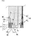
- FIGs. 4A and 4B are cross-sectional views of an injector unit 6B, each illustrating a joint portion of a combustion pressure sensor 8B and an injector 7B.
- FIGs. 5A to 5D illustrate an assembly process.
- a feature of the first exemplary embodiment lies in that a space for joining is provided between the inner cylindrical portion and the tip portion of the injector, and a connecting member is disposed using this space.
- the connecting member includes a distortion buffer portion. With the distortion buffer portion in between, one end of the connecting member is weld-fixed to the combustion pressure sensor and the other end is weld-fixed to the injector.
- FIGs. 4A and 4B [Explanation of the configuration: FIGs. 4A and 4B]
- FIG. 4A is a cross-sectional view of the injector unit before welding
- FIG. 4B is a partial cross-sectional view of the injector unit after welding.
- FIG. 4A shows the same part as that of FIG. 3 explained above.
- the injector unit of FIG. 4A is different from that of FIG. 3 in that the injector unit is provided with a space V around the joint portion on the front end surface side, and a weld ring 18 is disposed in the space V as a connecting member. Since other basic configuration is the same as that of FIG. 3 , reference signs for the same parts and the same elements are omitted in the figure and the reference signs may be included in the following explanation as necessary.
- the injector unit 6B is composed of: the combustion pressure sensor 8B attached with the weld ring 18; and the injector 7B that has a space for disposing the weld ring 18.
- an inner cylindrical portion 12B constituting a case portion of the combustion pressure sensor 8B has a simple cylindrical shape without the protruding portion 12a, unlike the inner cylindrical portion 12 of the basic configuration shown in FIG. 3 .
- the injector 7B is shaped to have a tapered clearance portion with a step portion 7d formed at the tip portion 7a, unlike the injector 7A of the basic configuration shown in FIG. 3 .
- the space V is formed at the front end surface side of the mounting portion.
- the weld ring 18 consists of a rectangular portion 18a at the front end surface side, a rectangular portion 18b at the back end surface side, and an intermediate rib portion 18c (an example of the distortion buffer portion).
- the width u2 of the rectangular portion 18b at the back end surface side is set smaller than the width u1 of the rectangular portion 18a at the front end surface side.
- the weld ring 18 of this cross sectional shape is cylindrical, and fitted to the inner diameter of the inner cylindrical portion 12B.
- the weld ring 18 is joined at the welding portion WO with its end portion at the front end surface side being aligned with the inner cylindrical portion 12B.
- weld ring 18 and the inner cylindrical portion 12B are joined to each other prior to the assembly process of the combustion pressure sensor, which will be described later.
- the rectangular portion 18b at the back end surface side of the weld ring 18 is configured to contact the step portion 7d provided to the injector 7B.
- the welding portion W5 is a portion where the step portion 7c provided to the rear part of the injector 7B engages with the step portion 13a provided to the supporting member 13.
- welding heat is transmitted to the weld ring 18 and the injector 7B. Since the weld ring 18 has a smaller thickness and a smaller heat capacity than the injector 7B, welding heat is first transmitted to the weld ring 18 side. This causes the back end surface side of the weld ring 18 (the rectangular portion 18b side) to expand, deforming the weld ring 18 into a tapered shape (trumpet shape) with an angle ⁇ 1.
- the rectangular portion 18b of the weld ring 18 is weld-fixed onto the step portion 7d provided to the injector 7B.
- the intermediate rib portion 18c with a predetermined length is present between the rectangular portion 18b at the back end surface side and the rectangular portion 18a at the front end surface side. This allows the rib portion 18c to absorb the influence, such as thermal distortion, that occurs from welding the rectangular portion 18b to the step portion 7d, thus making the inner cylindrical portion 12B unaffected by the influence of distortion occurring in the joint portion.
- the injector unit 6B with minimized heat deformation is thus formed. It should be noted that by forming the weld ring 18 with a material having a linear expansion coefficient comparable to the material for the injector 7B, it is possible to minimize the influence of distortion more effectively.
- the piezoelectric elements 16 constituting a piezoelectric element group each have a back end surface that is electrically connected to a ground electrode layer (not shown) provided to the supporting member 13, via a rear side electrode (not shown) provided to each back end surface of the piezoelectric elements 16. This results in the rear side electrodes of the piezoelectric elements 16 being electrically connected to the supporting member 13 and grounded.
- each front end surface of the piezoelectric elements 16 is electrically connected to a ring-shaped output electrode layer (not shown) formed on the back end surface of the pressure transmission ring 15, via a front side electrode (not shown) provided to each front end surface of the piezoelectric elements 16.
- a front side electrode not shown
- the output electrode layer provided to the pressure transmission ring 15 is electrically connected to the connection terminal 52 by a spring force of the coil spring 56, via an abutting portion on the front end surface side of the connection terminal 52. Further, the connection terminal 52 is electrically connected to a conductor portion of the transmission wire 51, from a connecting member on the back end surface side of the connection terminal 52 and through the connection pipe 53.
- connection terminal 52 to the connection pipe 53 and a path from the conductor portion of the transmission wire 51 to the electrical connector portion 70 of the injector are electrically insulated from the outer cylindrical portion 11, the inner cylindrical portion 12, the supporting member 13 and the metal part of the injector by the positioning tube 55, the O-ring 57, and an insulating resin layer formed on the surface of the transmission wire 51, which are made of an insulator.
- the injector unit 6A when the injector unit 6A is mounted to the cylinder head 4 of the internal combustion engine 1 shown in FIG. 1 , within the communication hole 4a of the cylinder head 4 shown in FIG. 2 , the flange portion 6b provided on the outer circumference of the injector is clamped and fixed to the end surface of the third hole portion 4d provided in the communication hole 4a.
- the injector unit 6A is thus electrically connected to the cylinder head 4 and grounded to the vehicle body.
- the charge signal transmitted to the conductor portion is then supplied to the signal processing portion 100 via the electrical connector portion 70 of the injector 7A.
- the charge signal supplied to the signal processor 100 is then subjected to signal processing, and the voltage corresponding to the charge is supplied to the controlling device 200.
- FIGS. 5A-5D [Explanation of assembly processes: FIGS. 5A-5D]
- FIGS. 5A-5D are cross-sectional views each illustrating a process of assembling the combustion pressure sensor 8B and the injector unit 6B.
- FIG. 5A illustrates the weld ring 18
- FIG. 5B illustrates a process of joining the inner cylindrical portion 12B and the weld ring 18
- FIG. 5C illustrates a process of assembling the pressure detection portion 10B
- FIG. 5D illustrates a process of joining the combustion pressure sensor 8B and the injector 7B.
- the assembly processes described below require jigs including a welding jig, an assembly jig and an adjustment jig, detailed description of the jigs is omitted.
- FIG. 5A illustrates a cross section of the weld ring 18.
- the weld ring 18 includes the rectangular portion 18a at the front end surface side, the rectangular portion 18b at the back end surface side, and the intermediate rib portion 18c connecting the rectangular portions 18a and 18b.
- FIG. 6B illustrates a process of joining the inner cylindrical portion 12B and the weld ring 18.
- the outer diameter of the weld ring 18 is fitted to the inner diameter of the inner cylindrical portion 12B.
- laser welding is performed along the entire circumference of the welding portion W0.
- FIG. 5C illustrates a process of assembling the pressure detection portion 10B and the transmission unit 50.
- the inner cylindrical portion 12B with the weld ring 18 obtained in the process shown in FIG. 5B , the outer cylindrical portion 11 and the pressure receiving member 14 are set to a predetermined assembly jig, and laser welding is performed along the entire circumference of the welding portions W1 and W2. Then, the pressure transmission ring 15, the piezoelectric elements 16, the transmission unit 50, and the supporting member 13 are stacked in this order inside the internal space 10b that is formed by the pressure receiving member 14, the inner cylindrical portion 12B, and the outer cylindrical portion 11.
- a load is applied from the back end surface side of the supporting member 13 to the front end surfaces of the inner cylindrical portion 12B and the outer cylindrical portion 11.
- the pressure receiving surface of the pressure receiving member 14 is kept in a free state.
- the load is applied to the piezoelectric elements 16 by utilizing the spring property of the pressure receiving portion of the pressure receiving member 14.
- FIG. 5D illustrates a process for joining the above described combustion pressure sensor 8B and the injector 7B.
- the injector 7B is mounted to the combustion pressure sensor 8B, and laser welding is performed along the entire circumference of the welding portions W5 and W6.
- the injector unit 6B is thus formed.
- the first exemplary embodiment of the Example 1 explained above provides the following advantageous effects.
- the connecting member (the weld ring) having a distortion buffer portion is provided to the joint portion of the combustion pressure sensor and the functional component. This enables to make the case portion of the combustion pressure sensor unaffected by the influence of deformation that occurs in the joint portion of the combustion pressure sensor and the functional component.
- the process of joining the inner cylindrical portion constituting the case portion and the connecting member (the weld ring) is performed prior to the process of assembling the combustion pressure sensor. This allows for adjustment to the assembly of the combustion pressure sensor by taking into account the influence of thermal deformation that occurs during joining the inner cylindrical portion and the connecting member. Thus, the influence of thermal deformation of the inner cylindrical portion of the case portion can be minimized.
- the connecting member is made of a material with a liner expansion coefficient comparable to that of the material for the joint portion of the functional component. This enables to minimize thermal deformation during weld-joining of the connecting member and the functional component.
- the above explanation of the combustion pressure sensor and the injector unit has been given using an example where a piezoelectric element is used for the pressure detection portion.
- other detection elements may be used, such as a distortion sensing element that uses a distortion resistance effect.
- the above explanation has been given using an example where multiple ring-shaped piezoelectric elements are used for the structure of the pressure detection portion.
- the structure of the pressure detection portion is not limited to this.
- the pressure detection portion may use a ring-shaped piezoelectric element.
- FIG. 6 is a cross-sectional view of an injector unit 6C, illustrating a joint portion of a combustion pressure sensor 8C and an injector 7B. The figure illustrates the same part as that shown in FIG. 4A explained above.
- a feature of the second exemplary embodiment lies in that the embodiment uses a weld ring of a different shape.
- a rectangular portion 19b on the back end surface side of a weld ring 19, which is weld-fixed to the injector, has the same width as an intermediate rib portion 19c.
- Using the weld ring of this shape can extend the length of the distortion buffer portion, enabling to further minimize the influence of thermal deformation on the case portion.
- FIG. 7 is a cross-sectional view of the injector unit 6C, illustrating a joint portion of the combustion pressure sensor 8C and the injector 7B. The figure illustrates the same part as that shown in FIG. 4A explained above.
- the third exemplary embodiment uses a weld ring of another different shape.
- a weld ring 20 includes a rectangular portion 20a on the front end surface side, a rectangular portion 20b on the back end surface side, and an intermediate rib portion 20c that has a curved shape.
- the same parts and the same elements are denoted by the same reference signs and the redundant explanation will be omitted.
- Using the weld ring of this shape can impart elasticity to the distortion buffer portion, enabling to further minimize the influence of thermal deformation on the case portion.
- FIG. 8 is a cross-sectional view of the injector unit 6C, illustrating a joint portion of the combustion pressure sensor 8C and the injector 7B. The figure illustrates the same part as that shown in FIG. 4A explained above.
- a weld ring 21 includes a rectangular portion 21a on the front end surface side, a rectangular portion 21b on the back end surface side, and an intermediate rib portion 21c.
- the rectangular portion 21b on the back end surface side extends toward the center of the injector along the step portion 7d of the injector.
- the rectangular portion 21a on the front end surface side has a chamfered portion 21d.
- the chamfered portion 21d is provided so that an outer shape of the weld ring 21 does not interfere with a laser light for laser-welding the step portion 7d of the injector and the rectangular portion 21b on the back end surface side.
- the chamfered portion 21d allows to secure a path of the laser light incident from the outside onto the rectangular portion 21b on the back end surface side. This enables to reliably weld the step portion 7d of the injection and the rectangular portion 21b on the back end surface side.
- FIG. 9 is a cross-sectional view of an injector unit 6D, illustrating a joint portion of a combustion pressure sensor 8D and the injector 7B. The figure illustrates the same part as that shown in FIG. 4A explained above.
- a feature of the fifth exemplary embodiment lies in that the shape corresponding to the weld ring is integrated into an inner cylindrical portion to form the inner cylindrical portion 12C.
- the same parts and the same elements are denoted by the same reference signs and the redundant explanation will be omitted.
- Using the inner cylindrical portion of this shape can remove the process of joining the inner cylindrical portion and the weld ring, and also eliminate deformation of the inner cylindrical portion during joining.
- the inner cylindrical portion is provided with a separate or an integral weld ring in the first to fifth exemplary embodiments of Example 1, the weld ring may be provided to the pressure receiving member instead of the inner cylindrical portion. Such configuration also provides the same advantages effects.
- FIG. 10 is a cross-sectional view according to the first exemplary embodiment of Example 2, illustrating a joint portion of the combustion pressure sensor and the spark plug.
- the figure illustrates the same part as that shown in FIG. 4A explained above.
- the spark plug faces the combustion chamber of the internal combustion engine.
- the spark plug has the same configuration as the exemplary embodiments of Example 1 in that the spark plug is mounted with the ring-shaped combustion pressure sensor of the present invention to detect a combustion pressure.
- Example 2 The first exemplary embodiment of Example 2 will be explained using FIG. 10 .
- the combustion pressure sensor 8B has the same configuration as that explained in FIG. 4A .
- the spark plug 5 has a different function from the injector, they are the same in that a step portion for mounting the combustion pressure sensor is provided to the tip portion and the combustion pressure sensor is joined to detect a combustion pressure.
- the spark plug 5 is provided with a step portion 5d on the front end surface side to form a space V in which the weld ring 18 is joined with the spark plug 5.
- the welding portion W5 is a portion where a step portion 5c in a rear part of the spark plug 5 engages with the protruding portion 13a of the supporting member 13.
- the welding portion W6 is a portion where a step portion 5d on the front end surface side of the spark plug 5 engages with the rectangular portion 18b on the back end surface side of the weld ring 18. Laser welding is performed along the entire circumference of the welding portions W5 and W6, thus forming a spark plug unit 9A.
- the combustion pressure sensor 8B of the present invention may be mounted to the tip portion of not only the injector but also the spark plug. Joining them with the weld ring enables to minimize the influence of thermal deformation on the case portion.
- the spark plug unit 9A uses the same weld ring 18 as that explained in FIG. 4A , the weld ring is not limited to this. It is needless to say that the weld ring of the structure as explained in FIGS. 6 and 8 is also applicable.
Landscapes
- Chemical & Material Sciences (AREA)
- Engineering & Computer Science (AREA)
- Combustion & Propulsion (AREA)
- Physics & Mathematics (AREA)
- General Physics & Mathematics (AREA)
- Measuring Fluid Pressure (AREA)
- Combined Controls Of Internal Combustion Engines (AREA)
- Ignition Installations For Internal Combustion Engines (AREA)
- Fuel-Injection Apparatus (AREA)
- Spark Plugs (AREA)
Applications Claiming Priority (2)
| Application Number | Priority Date | Filing Date | Title |
|---|---|---|---|
| JP2015061557 | 2015-03-24 | ||
| PCT/JP2016/056500 WO2016152429A1 (ja) | 2015-03-24 | 2016-03-02 | 燃焼圧センサ |
Publications (2)
| Publication Number | Publication Date |
|---|---|
| EP3276325A1 true EP3276325A1 (de) | 2018-01-31 |
| EP3276325A4 EP3276325A4 (de) | 2018-11-14 |
Family
ID=56979083
Family Applications (1)
| Application Number | Title | Priority Date | Filing Date |
|---|---|---|---|
| EP16768332.5A Withdrawn EP3276325A4 (de) | 2015-03-24 | 2016-03-02 | Verbrennungsdrucksensor |
Country Status (5)
| Country | Link |
|---|---|
| US (1) | US20180058968A1 (de) |
| EP (1) | EP3276325A4 (de) |
| JP (1) | JP6404455B2 (de) |
| CN (1) | CN107430041A (de) |
| WO (1) | WO2016152429A1 (de) |
Families Citing this family (2)
| Publication number | Priority date | Publication date | Assignee | Title |
|---|---|---|---|---|
| DE102017113838A1 (de) * | 2017-06-22 | 2018-12-27 | Man Diesel & Turbo Se | Brennkraftmaschine |
| JP6855367B2 (ja) * | 2017-12-19 | 2021-04-07 | 日本特殊陶業株式会社 | 筒内圧センサ |
Family Cites Families (14)
| Publication number | Priority date | Publication date | Assignee | Title |
|---|---|---|---|---|
| JP2000155062A (ja) * | 1998-11-19 | 2000-06-06 | Nippon Seiki Co Ltd | 圧力検出器 |
| JP2001330529A (ja) * | 2000-05-19 | 2001-11-30 | Yokogawa Electric Corp | 圧力センサ |
| JP4620882B2 (ja) * | 2001-02-20 | 2011-01-26 | 日本特殊陶業株式会社 | 圧力センサ内蔵プラグ |
| JP2003232268A (ja) * | 2002-02-08 | 2003-08-22 | Hitachi Ltd | 電磁式燃料噴射弁 |
| JP2006300046A (ja) * | 2004-08-05 | 2006-11-02 | Ngk Spark Plug Co Ltd | 燃焼圧検知機能付グロープラグ |
| JP2008002809A (ja) * | 2006-06-20 | 2008-01-10 | Denso Corp | 燃焼圧センサー |
| EP2087333B1 (de) * | 2006-11-10 | 2011-08-17 | Kistler Holding AG | Drucksensor für messungen in heissen, dynamischen prozessen |
| FR2935798B1 (fr) * | 2008-09-08 | 2010-09-17 | Continental Automotive France | Dispositif integrant un capteur de pression pour la mesure de pressions au sein d'une chambre de combustion d'un moteur |
| JP5169951B2 (ja) * | 2009-04-03 | 2013-03-27 | 株式会社デンソー | 燃料噴射弁 |
| JP2010249061A (ja) * | 2009-04-17 | 2010-11-04 | Denso Corp | 燃料噴射弁 |
| JP5921240B2 (ja) * | 2012-02-10 | 2016-05-24 | 日立オートモティブシステムズ株式会社 | 燃料噴射弁 |
| DE102012202058A1 (de) * | 2012-02-10 | 2013-08-14 | Robert Bosch Gmbh | Membran für Brennraumdrucksensor |
| JP6069329B2 (ja) * | 2012-08-30 | 2017-02-01 | シチズンファインデバイス株式会社 | 圧力検出装置 |
| JP6286355B2 (ja) * | 2012-09-27 | 2018-02-28 | シチズンファインデバイス株式会社 | 内燃機関用燃焼圧センサ付き機能部品ユニット |
-
2016
- 2016-03-02 WO PCT/JP2016/056500 patent/WO2016152429A1/ja not_active Ceased
- 2016-03-02 EP EP16768332.5A patent/EP3276325A4/de not_active Withdrawn
- 2016-03-02 US US15/557,942 patent/US20180058968A1/en not_active Abandoned
- 2016-03-02 CN CN201680017305.0A patent/CN107430041A/zh active Pending
- 2016-03-02 JP JP2017508148A patent/JP6404455B2/ja not_active Expired - Fee Related
Also Published As
| Publication number | Publication date |
|---|---|
| JPWO2016152429A1 (ja) | 2018-02-22 |
| CN107430041A (zh) | 2017-12-01 |
| JP6404455B2 (ja) | 2018-10-10 |
| EP3276325A4 (de) | 2018-11-14 |
| WO2016152429A1 (ja) | 2016-09-29 |
| US20180058968A1 (en) | 2018-03-01 |
Similar Documents
| Publication | Publication Date | Title |
|---|---|---|
| US6979801B2 (en) | Glow plug with built-in combustion pressure sensor and manufacturing method thereof | |
| US6411038B2 (en) | Installation structure of engine component with combustion pressure sensor in engine | |
| US8217309B2 (en) | Glow plug with pressure sensing canister | |
| EP1486653B1 (de) | Verbrennungsdrucksensor | |
| US20040182144A1 (en) | Glow plug with built-in combustion pressure sensor | |
| US8365705B2 (en) | Fuel injection valve | |
| EP2827117B1 (de) | Verbrennungsmotor mit verbrennungsdruckdetektor und verbrennungsdruckdetektor | |
| CN101858287A (zh) | 燃料喷射阀 | |
| JP2010242578A (ja) | 燃料噴射弁 | |
| CN106415229B (zh) | 燃烧压力传感器及其制造方法 | |
| WO2013147260A1 (ja) | 圧力検出装置、圧力検出装置付き内燃機関 | |
| JP6066767B2 (ja) | 内燃機関用燃焼圧センサ及びその製造方法。 | |
| HK1204031A1 (en) | Combustion pressure detection device, and internal combustion engine equipped with combustion pressure detection device | |
| US9874195B2 (en) | Pressure-measuring glow plug device | |
| EP3276325A1 (de) | Verbrennungsdrucksensor | |
| JP6286355B2 (ja) | 内燃機関用燃焼圧センサ付き機能部品ユニット | |
| JP2013195163A (ja) | 燃焼圧検出装置付き内燃機関および燃焼圧検出装置 | |
| JP5883691B2 (ja) | 燃焼圧検出装置付き内燃機関 | |
| JP2005010137A (ja) | ガスセンサ及びその製造方法 | |
| JP2007085577A (ja) | 燃焼圧センサ付きグロープラグ | |
| JP2006308245A (ja) | 燃焼圧検知センサ付きグロープラグ | |
| HK1204047B (en) | Internal combustion engine fitted with combustion pressure detection device |
Legal Events
| Date | Code | Title | Description |
|---|---|---|---|
| STAA | Information on the status of an ep patent application or granted ep patent |
Free format text: STATUS: THE INTERNATIONAL PUBLICATION HAS BEEN MADE |
|
| PUAI | Public reference made under article 153(3) epc to a published international application that has entered the european phase |
Free format text: ORIGINAL CODE: 0009012 |
|
| STAA | Information on the status of an ep patent application or granted ep patent |
Free format text: STATUS: REQUEST FOR EXAMINATION WAS MADE |
|
| 17P | Request for examination filed |
Effective date: 20170918 |
|
| AK | Designated contracting states |
Kind code of ref document: A1 Designated state(s): AL AT BE BG CH CY CZ DE DK EE ES FI FR GB GR HR HU IE IS IT LI LT LU LV MC MK MT NL NO PL PT RO RS SE SI SK SM TR |
|
| AX | Request for extension of the european patent |
Extension state: BA ME |
|
| DAV | Request for validation of the european patent (deleted) | ||
| DAX | Request for extension of the european patent (deleted) | ||
| A4 | Supplementary search report drawn up and despatched |
Effective date: 20181016 |
|
| RIC1 | Information provided on ipc code assigned before grant |
Ipc: G01L 23/22 20060101AFI20181009BHEP Ipc: F02D 35/00 20060101ALI20181009BHEP |
|
| STAA | Information on the status of an ep patent application or granted ep patent |
Free format text: STATUS: EXAMINATION IS IN PROGRESS |
|
| 17Q | First examination report despatched |
Effective date: 20190918 |
|
| STAA | Information on the status of an ep patent application or granted ep patent |
Free format text: STATUS: THE APPLICATION HAS BEEN WITHDRAWN |
|
| 18W | Application withdrawn |
Effective date: 20210126 |