EP3276291A1 - Verstärkungselement für plattenwärmetauscher - Google Patents
Verstärkungselement für plattenwärmetauscher Download PDFInfo
- Publication number
- EP3276291A1 EP3276291A1 EP17185176.9A EP17185176A EP3276291A1 EP 3276291 A1 EP3276291 A1 EP 3276291A1 EP 17185176 A EP17185176 A EP 17185176A EP 3276291 A1 EP3276291 A1 EP 3276291A1
- Authority
- EP
- European Patent Office
- Prior art keywords
- dish
- mounting plate
- reinforcing element
- plate
- attached
- Prior art date
- Legal status (The legal status is an assumption and is not a legal conclusion. Google has not performed a legal analysis and makes no representation as to the accuracy of the status listed.)
- Granted
Links
Images

Classifications
-
- F—MECHANICAL ENGINEERING; LIGHTING; HEATING; WEAPONS; BLASTING
- F28—HEAT EXCHANGE IN GENERAL
- F28D—HEAT-EXCHANGE APPARATUS, NOT PROVIDED FOR IN ANOTHER SUBCLASS, IN WHICH THE HEAT-EXCHANGE MEDIA DO NOT COME INTO DIRECT CONTACT
- F28D9/00—Heat-exchange apparatus having stationary plate-like or laminated conduit assemblies for both heat-exchange media, the media being in contact with different sides of a conduit wall
- F28D9/0031—Heat-exchange apparatus having stationary plate-like or laminated conduit assemblies for both heat-exchange media, the media being in contact with different sides of a conduit wall the conduits for one heat-exchange medium being formed by paired plates touching each other
- F28D9/0043—Heat-exchange apparatus having stationary plate-like or laminated conduit assemblies for both heat-exchange media, the media being in contact with different sides of a conduit wall the conduits for one heat-exchange medium being formed by paired plates touching each other the plates having openings therein for circulation of at least one heat-exchange medium from one conduit to another
- F28D9/005—Heat-exchange apparatus having stationary plate-like or laminated conduit assemblies for both heat-exchange media, the media being in contact with different sides of a conduit wall the conduits for one heat-exchange medium being formed by paired plates touching each other the plates having openings therein for circulation of at least one heat-exchange medium from one conduit to another the plates having openings therein for both heat-exchange media
-
- F—MECHANICAL ENGINEERING; LIGHTING; HEATING; WEAPONS; BLASTING
- F28—HEAT EXCHANGE IN GENERAL
- F28F—DETAILS OF HEAT-EXCHANGE AND HEAT-TRANSFER APPARATUS, OF GENERAL APPLICATION
- F28F9/00—Casings; Header boxes; Auxiliary supports for elements; Auxiliary members within casings
- F28F9/001—Casings in the form of plate-like arrangements; Frames enclosing a heat exchange core
- F28F9/002—Casings in the form of plate-like arrangements; Frames enclosing a heat exchange core with fastening means for other structures
-
- F—MECHANICAL ENGINEERING; LIGHTING; HEATING; WEAPONS; BLASTING
- F28—HEAT EXCHANGE IN GENERAL
- F28F—DETAILS OF HEAT-EXCHANGE AND HEAT-TRANSFER APPARATUS, OF GENERAL APPLICATION
- F28F9/00—Casings; Header boxes; Auxiliary supports for elements; Auxiliary members within casings
- F28F9/007—Auxiliary supports for elements
- F28F9/0075—Supports for plates or plate assemblies
-
- F—MECHANICAL ENGINEERING; LIGHTING; HEATING; WEAPONS; BLASTING
- F28—HEAT EXCHANGE IN GENERAL
- F28F—DETAILS OF HEAT-EXCHANGE AND HEAT-TRANSFER APPARATUS, OF GENERAL APPLICATION
- F28F2225/00—Reinforcing means
- F28F2225/04—Reinforcing means for conduits
-
- F—MECHANICAL ENGINEERING; LIGHTING; HEATING; WEAPONS; BLASTING
- F28—HEAT EXCHANGE IN GENERAL
- F28F—DETAILS OF HEAT-EXCHANGE AND HEAT-TRANSFER APPARATUS, OF GENERAL APPLICATION
- F28F2280/00—Mounting arrangements; Arrangements for facilitating assembling or disassembling of heat exchanger parts
- F28F2280/06—Adapter frames, e.g. for mounting heat exchanger cores on other structure and for allowing fluidic connections
-
- Y—GENERAL TAGGING OF NEW TECHNOLOGICAL DEVELOPMENTS; GENERAL TAGGING OF CROSS-SECTIONAL TECHNOLOGIES SPANNING OVER SEVERAL SECTIONS OF THE IPC; TECHNICAL SUBJECTS COVERED BY FORMER USPC CROSS-REFERENCE ART COLLECTIONS [XRACs] AND DIGESTS
- Y10—TECHNICAL SUBJECTS COVERED BY FORMER USPC
- Y10S—TECHNICAL SUBJECTS COVERED BY FORMER USPC CROSS-REFERENCE ART COLLECTIONS [XRACs] AND DIGESTS
- Y10S165/00—Heat exchange
- Y10S165/906—Reinforcement
-
- Y—GENERAL TAGGING OF NEW TECHNOLOGICAL DEVELOPMENTS; GENERAL TAGGING OF CROSS-SECTIONAL TECHNOLOGIES SPANNING OVER SEVERAL SECTIONS OF THE IPC; TECHNICAL SUBJECTS COVERED BY FORMER USPC CROSS-REFERENCE ART COLLECTIONS [XRACs] AND DIGESTS
- Y10—TECHNICAL SUBJECTS COVERED BY FORMER USPC
- Y10S—TECHNICAL SUBJECTS COVERED BY FORMER USPC CROSS-REFERENCE ART COLLECTIONS [XRACs] AND DIGESTS
- Y10S165/00—Heat exchange
- Y10S165/916—Oil cooler
Definitions
- This invention relates to heat exchangers, and in particular to heat exchangers formed of a plurality of stacked or nested dish-type plates with overlapping peripheral walls.
- Nested dish plate heat exchangers have been made in the past where a plurality of stacked plates having overlapping peripheral side walls are put together to define hollow fluid passages between the plates, usually with different fluids in heat exchange relationship in alternating spaces between the plates.
- a base plate or mounting plate is attached to an uppermost or a lowermost one of the stacked plates, and the mounting plate has holes or fasteners to attach the heat exchanger to a piece of equipment, such as an automobile engine. Oil from the engine passes through openings in the mounting plate and engine coolant passes through other inlet and outlet holes in the mounting plate, or fittings attached to the heat exchanger in order to cool the engine oil in use.
- the plates are usually made of thin material. Also, the plates are often made of aluminum which has inherently lower mechanical strength relative to ferrous alloys, particularly after brazing.
- a difficulty with this is that some of the dish plates, usually the ones attached to the mounting plate, are prone to fatigue fracture due to vibration, mounting plate deformation, thermal stresses and internal pressure stresses transmitted from the engine to the nested dish plates through the mounting plate, and also from the coolant hoses attached to the heat exchanger.
- Base plate or mounting plate deformation presents a significant problem since mounting plates may tend to form poor braze joints with the lowermost plate in the stack of nested dish plates and are, therefore, prone to failure.
- a reinforcing element surrounds at least a portion of a regular heat exchanger dish plate attached to the mounting plate.
- the reinforcing element has a base flange attached to the mounting plate, and a peripheral flange in parallel, overlapping contact with the inclined peripheral wall of the regular heat exchanger dish plate.
- a reinforcing element for a dish plate heat exchanger having a mounting plate and a plurality of nested dish plates mounted thereon, the dish plates having inclined peripheral, overlapping walls and the mounting plate extending beyond the outer periphery of the walls of the nested dish plates.
- the reinforcing element comprises a base flange adapted to be attached to the mounting plate extending beyond the outer periphery of the walls of the nested dish plates.
- a peripheral flange is attached to the base flange.
- the peripheral flange is adapted to be in parallel, overlapping contact with the inclined peripheral wall of at least one dish plate attached to the mounting plate.
- a dish plate heat exchanger comprising a mounting plate and a plurality of nested dish plates mounted on the mounting plate.
- the dish plates have inclined, peripheral, overlapping walls, the mounting plate extending beyond the outer periphery of the walls of the nested dish plates.
- a reinforcing element has a base flange attached to the mounting plate extending beyond the outer periphery of the nested dish plates.
- the reinforcing element has a peripheral flange attached to the base flange. The peripheral flange is attached in parallel, overlapping engagement with the inclined peripheral wall of at least one dish plate attached to the mounting plate.
- a reinforcing element for a dish plate heat exchanger having a mounting plate and a plurality of nested dish plates mounted thereon, the dish plates having inclined, peripheral, overlapping walls, the mounting plate extending beyond the outer periphery of the walls of the nested dish plates.
- the reinforcing element comprises a base portion adapted to be positioned between the mounting plate and the plurality of nested dish plates.
- a peripheral flange is attached to the periphery of at least a portion of the base portion, the peripheral flange being adapted to be in parallel, overlapping contact with the inclined peripheral wall of at least one dish plate in the plurality of nested dish plates.
- the reinforcing element also includes a tongue portion extending outwardly from the base portion, the tongue portion being configured to overlap a high-stress area of the mounting plate extending beyond the outer periphery of the walls of the nested dish plates.
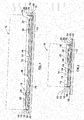
- a nested dish type heat exchanger 10 is shown in Figure 1 . Only a few of the nested dish plates 12 are shown for illustration purposes, the remainder being represented by chain-dotted lines. The nested dish plates 12 are mounted on a mounting plate 13.
- the nested dish plates 12 have bottom walls 15 defining inlet and outlet openings 14, 16 for a first heat exchange fluid, such as engine oil, and embossments or bosses 18 defining further inlet and outlet openings 20, 22 for a second heat exchanger fluid, such as engine coolant.
- Inlet and outlet fittings are also provided for the supply and return of engine coolant to inlet and outlet openings 20, 22.
- mounting plate 13 could be provided with inlet and outlet openings (not shown) communicating with dish plate inlet and outlet openings 20, 22, if desired.
- mounting plate 13 could have one inlet opening communicating with dish plate inlet openings 20, and one outlet fitting (not shown) could be provided in heat exchanger 10 communicating with dish plate outlet openings 22.
- the dish plates 12 are stacked with alternating plates turned 180 degrees to one another, so that inlet and outlet openings 14, 16 communicate with spaces or flow passages 24 between every other pair of adjacent plates. Similarly, inlet and outlet openings 20, 22 communicate with spaces or flow passages 26 in between every other alternating pair of adjacent plates.
- a first heat exchange fluid such as engine oil
- a second heat exchange fluid such as engine coolant
- dish plates 12 have inclined, peripheral, overlapping side walls 28.
- Each peripheral wall 28 extends about, or just slightly more than, half way up the peripheral wall 28 next above it. This provides a double thickness sidewall for heat exchanger 10, except in the case of the lowermost dish plate 12'.
- heat exchanger 10 includes a reinforcing element 30.
- Reinforcing element 30 includes a base flange 32 attached to mounting plate 13, such as by brazing.
- Base flange 32 may have a peripheral configuration to match mounting plate 13, in which case, base flange 32 would be provided with mounting holes 33 to match corresponding mounting holes in mounting plate 13.
- Reinforcing element 30 surrounds the nested dish plates 12.
- Reinforcing element 30 also has a peripheral flange 34 attached to base flange 32. Peripheral flange 34 is attached in parallel, overlapping engagement with the inclined peripheral wall 28 of the lowermost dish plate 12', which in turn is attached to mounting plate 13.
- Peripheral flange 34 could, with suitable modifications, overlap more than one peripheral wall 28 on multiple dish plates 12, but it at least overlaps the one peripheral wall 28 on the dish plate 12' attached to mounting plate 13. That way, heat exchanger 10 has a double side wall thickness throughout its entire height.
- Reinforcing element 30 also has a base flange 42 which is attached to mounting plate 13 surrounding dish plates 12, and a peripheral flange 44 attached to base flange 42. Peripheral flange 44 is attached in parallel, overlapping engagement with the inclined peripheral wall 28 of the at least one dish plate 12' attached to mounting plate 13.
- Reinforcing element 40 preferably is made by roll forming and is then bent into an annular configuration to surround dish plate 12. Reinforcing element 40 thus would have a small gap 46 (emphasized in Figure 5 for the purposes of illustrations). Gap 46 could be closed or filled in or covered during assembly of heat exchanger 10, if desired. Gap 46 could also be made larger, if no reinforcement of heat exchanger 10 is needed in the area of the gap.
- reinforcing element 50 has a base flange 52 and an inverted peripheral flange 54, wherein the peripheral flange 54 is in the form of an inverted V-shape.
- Figure 8 shows another variation of a nested dish plate heat exchanger where the dish plates 12 are inverted.
- Reinforcing element 58 could be the same as either of the reinforcing elements 30 or 40.
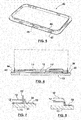
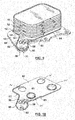
- FIGS 9 and 10 show another embodiment of a reinforcing element according to the present invention in use with a nested dish type heat exchanger as described in connection with Figures 1-8 . Therefore, although not visible in Figure 9 , dish plates 12 include inlet and outlet openings for the flow of first and second heat exchange fluids through the heat exchanger as described in connection with Figure 1 . However, in this embodiment, reinforcing element 60 has a base portion 64 that is positioned between the stack of nested dish plates 12 and mounting plate 13 (see Figure 10 ). Base portion 64 includes inlet and outlet openings 14', 16', 20', 22' corresponding to the openings in plates 12.
- the reinforcing element 60 is provided with a peripheral flange 62 that does not completely surround the dish plate 12'. Rather, the peripheral flange 62 terminates at an end edge 63 along one of the sides of the nested dish plates which illustrates that the peripheral flange 63 does not need to continuously surround the dish plates 12 in all cases.
- the base 64 extends slightly beyond the periphery of the nested dish plates 12 in the areas where there is no peripheral flange 62.
- Reinforcing element 60 is also formed with an extended portion or tongue portion 66 that extends from the base portion 64 of the reinforcing element 60 and is configured to overlap a portion of the mounting plate 13 that is subject to higher stresses.
- Peripheral flange 62 follows the periphery of at least a portion of tongue portion 66.
- the tongue portion 66 is formed with a pair of reinforcing ribs 68 projecting upwardly from the surface of the tongue portion 66 to increase the rigidity of the tongue portion 66, thereby increasing the overall strength of the reinforcing member 60.
- the tongue portion 66 also provides additional reinforcement around mounting hole 35 which may also be subject to higher stresses due to flexing or deformation of the mounting plate 13 in this area.
- the reinforcing element shown in Figures 9 and 10 shows the tongue portion 66 extending from the base portion 64 that is positioned between the lowermost nested dish plate 12' and mounting plate 13, it will be understood that a similar tongue portion having reinforcing ribs and a peripheral flange can be incorporated into any one of the reinforcing elements shown in Figures 1-8 so as to provide additional strength in areas where the mounting plate 13 is subject to higher stress concentrations.
- the tongue portion would extend from a section of base flange 32, 42, or 52.
- gap 46 could be made larger if no reinforcement of heat exchanger 10 is needed in the area of the gap.
- the reinforcing element 40 could be made in smaller, individual segments that are positioned around the nested dish plates 12 at only high-stress areas rather than having the reinforcing element 40 surround the entire stack of nested dish plates 12.
- the reinforcing element 30, 40 can also be formed by stamping. Any suitable material may be used to form the reinforcing element; however it is possible to use one-sided clad braze sheet for most if not all of the embodiments discussed above.
- the present subject-matter includes, inter alia, the following aspects
Landscapes
- Engineering & Computer Science (AREA)
- Physics & Mathematics (AREA)
- Thermal Sciences (AREA)
- Mechanical Engineering (AREA)
- General Engineering & Computer Science (AREA)
- Heat-Exchange Devices With Radiators And Conduit Assemblies (AREA)
- Details Of Heat-Exchange And Heat-Transfer (AREA)
Applications Claiming Priority (3)
| Application Number | Priority Date | Filing Date | Title |
|---|---|---|---|
| US72375505P | 2005-10-05 | 2005-10-05 | |
| PCT/CA2006/001638 WO2007038871A1 (en) | 2005-10-05 | 2006-10-05 | Reinforcement for dish plate heat exchangers |
| EP06790798.0A EP1931932B1 (de) | 2005-10-05 | 2006-10-05 | Verstärkung für tellerplattenwärmetauscher |
Related Parent Applications (2)
| Application Number | Title | Priority Date | Filing Date |
|---|---|---|---|
| EP06790798.0A Division-Into EP1931932B1 (de) | 2005-10-05 | 2006-10-05 | Verstärkung für tellerplattenwärmetauscher |
| EP06790798.0A Division EP1931932B1 (de) | 2005-10-05 | 2006-10-05 | Verstärkung für tellerplattenwärmetauscher |
Publications (2)
| Publication Number | Publication Date |
|---|---|
| EP3276291A1 true EP3276291A1 (de) | 2018-01-31 |
| EP3276291B1 EP3276291B1 (de) | 2019-07-24 |
Family
ID=37905942
Family Applications (2)
| Application Number | Title | Priority Date | Filing Date |
|---|---|---|---|
| EP17185176.9A Active EP3276291B1 (de) | 2005-10-05 | 2006-10-05 | Plattenwärmetauscher mit verstärkungselement |
| EP06790798.0A Active EP1931932B1 (de) | 2005-10-05 | 2006-10-05 | Verstärkung für tellerplattenwärmetauscher |
Family Applications After (1)
| Application Number | Title | Priority Date | Filing Date |
|---|---|---|---|
| EP06790798.0A Active EP1931932B1 (de) | 2005-10-05 | 2006-10-05 | Verstärkung für tellerplattenwärmetauscher |
Country Status (5)
| Country | Link |
|---|---|
| US (2) | US8181695B2 (de) |
| EP (2) | EP3276291B1 (de) |
| CN (1) | CN101317069B (de) |
| CA (1) | CA2624672C (de) |
| WO (1) | WO2007038871A1 (de) |
Families Citing this family (46)
| Publication number | Priority date | Publication date | Assignee | Title |
|---|---|---|---|---|
| EP3276291B1 (de) * | 2005-10-05 | 2019-07-24 | Dana Canada Corporation | Plattenwärmetauscher mit verstärkungselement |
| DE102006022445A1 (de) | 2006-05-13 | 2007-11-15 | Modine Manufacturing Co., Racine | Wärmetauscher, insbesondere Ölkühler |
| SE531511C2 (sv) * | 2007-09-05 | 2009-05-05 | Alfa Laval Corp Ab | Värmeväxlare |
| US20090242496A1 (en) * | 2008-03-31 | 2009-10-01 | Nielsen & Bainbridge Llc | Matboard corner organizing system |
| FR2931517B1 (fr) * | 2008-05-20 | 2012-09-21 | Valeo Sys Controle Moteur Sas | Dispositif d'admission de gaz |
| DE102009030095A1 (de) * | 2009-06-22 | 2010-12-23 | Behr Gmbh & Co. Kg | Stapelscheibenkühler |
| AT508537B1 (de) * | 2009-07-16 | 2011-04-15 | Mahle Int Gmbh | Plattenwärmetauscher mit mehreren übereinander gestapelten platten |
| US20110024095A1 (en) * | 2009-07-30 | 2011-02-03 | Mark Kozdras | Heat Exchanger with End Plate Providing Mounting Flange |
| DE102010001828A1 (de) * | 2010-02-11 | 2011-08-11 | Behr GmbH & Co. KG, 70469 | Stapelanordnung |
| DE102010063141A1 (de) * | 2010-12-15 | 2012-06-21 | Mahle International Gmbh | Wärmetauscher |
| DE102011080829A1 (de) * | 2011-08-11 | 2013-02-14 | Mahle International Gmbh | Plattenwärmetauscher |
| DE102011080828A1 (de) * | 2011-08-11 | 2013-02-14 | Mahle International Gmbh | Plattenwärmetauscher |
| DE102011080824A1 (de) * | 2011-08-11 | 2013-02-14 | Mahle International Gmbh | Plattenwärmetauscher |
| DE102012202276A1 (de) * | 2012-02-15 | 2013-08-22 | Mahle International Gmbh | Plattenwärmetauscher |
| FR2989771A1 (fr) * | 2012-04-19 | 2013-10-25 | Valeo Systemes Thermiques | Couvercle de faisceau d'echangeur de chaleur, faisceau comprenant un tel couvercle, echangeur de chaleur comprenant un tel faisceau et module d'admission d'air comprenant un tel echangeur. |
| FR2989770B1 (fr) | 2012-04-19 | 2018-06-15 | Valeo Systemes Thermiques | Couvercle de faisceau d'echangeur de chaleur, faisceau comprenant un tel couvercle, echangeur de chaleur comprenant un tel faisceau et module d'admission d'air comprenant un tel echangeur. |
| WO2013159172A1 (en) | 2012-04-26 | 2013-10-31 | Dana Canada Corporation | Heat exchanger with adapter module |
| US20130306291A1 (en) * | 2012-05-16 | 2013-11-21 | Chia-Ming Tung | Strip heatsink |
| US9945623B2 (en) | 2012-05-31 | 2018-04-17 | Dana Canada Corporation | Heat exchanger assemblies with integrated valve |
| WO2014048219A1 (zh) * | 2012-09-29 | 2014-04-03 | 杭州三花研究院有限公司 | 换热器集成组件及其制造方法 |
| CN103712383B (zh) * | 2012-09-29 | 2017-12-01 | 浙江三花汽车零部件有限公司 | 换热器与膨胀阀的集成组件及其制造方法 |
| CN104296422B (zh) * | 2013-07-19 | 2018-04-20 | 浙江三花汽车零部件有限公司 | 换热器集成组件 |
| CN103868394B (zh) * | 2012-12-13 | 2017-06-27 | 浙江三花汽车零部件有限公司 | 换热器的流通板、换热器的换热单元及换热器 |
| US20140238386A1 (en) * | 2013-02-23 | 2014-08-28 | Alexander Levin | Radiation absorbing metal pipe |
| DE102013214403A1 (de) * | 2013-07-23 | 2015-01-29 | Bayerische Motoren Werke Aktiengesellschaft | Grundplatte für einen Fahrzeugwärmetauscher, Verfahren zu ihrer Herstellung, Wärmetauscher und Ölfiltermodul |
| DE102013014434A1 (de) | 2013-08-30 | 2015-03-05 | Modine Manufacturing Company | Gelöteter Wärmetauscher |
| EP2886995B1 (de) | 2013-12-20 | 2017-03-08 | Alfa Laval Corporate AB | Plattenwärmetauscher mit Befestigungsflansch |
| ES2588828T3 (es) | 2013-12-20 | 2016-11-07 | Alfa Laval Corporate Ab | Intercambiador de calor de placas con brida de montaje |
| EP2886996B1 (de) | 2013-12-20 | 2016-07-13 | Alfa Laval Corporate AB | Plattenwärmetauscher mit Befestigungsflansch |
| JP6192564B2 (ja) | 2014-02-18 | 2017-09-06 | 日新製鋼株式会社 | プレート式熱交換器およびその製造方法 |
| EP3126771B1 (de) * | 2014-04-04 | 2022-04-06 | TitanX Holding AB | Wärmetauscher und verfahren zur herstellung eines wärmetauschers |
| DE102014212942A1 (de) * | 2014-07-03 | 2016-01-07 | Mahle International Gmbh | Stapelscheibenkühler |
| US20160061531A1 (en) * | 2014-08-27 | 2016-03-03 | Hangzhou Sanhua Research Institute Co., Ltd. | Heat exchanger |
| GB2541032A (en) * | 2015-08-07 | 2017-02-08 | Gm Global Tech Operations Llc | Oil cooler for an internal combustion engine |
| DE102016002621A1 (de) * | 2016-03-07 | 2017-09-07 | Modine Manufacturing Company | Multifunktionelle Grundplatte eines Wärmeübertragers |
| DE102016007089A1 (de) * | 2016-06-10 | 2017-06-29 | Modine Manufacturing Company | Flanschplatte mit Unterkühlfunktion |
| ES2702771A1 (es) * | 2017-09-05 | 2019-03-05 | Valeo Termico Sa | Conjunto de nucleo refrigerador y cubierta para un intercambiador de calor dispuesto embebido en un bloque motor o bloque de transmision de un vehiculo automovil |
| WO2019056114A1 (en) * | 2017-09-22 | 2019-03-28 | Dana Canada Corporation | LOCATED REINFORCEMENT FOR HEAT EXCHANGERS WITH STACKED STACKED SHEETS |
| CN111656124A (zh) | 2018-01-29 | 2020-09-11 | 达纳加拿大公司 | 结构支承的热交换器 |
| EP3598050B1 (de) | 2018-07-19 | 2021-03-03 | Valeo Termico S.A. | Verstärkter wärmetauscher mit einem stapel aus platten |
| EP3598051B1 (de) | 2018-07-19 | 2021-01-27 | Valeo Termico S.A. | Verstärkter wärmetauscher mit einem stapel aus platten |
| EP3598049B1 (de) | 2018-07-19 | 2022-08-10 | Valeo Termico S.A. | Verstärkter wärmetauscher mit einem stapel aus platten |
| US10900557B2 (en) | 2018-11-13 | 2021-01-26 | Dana Canada Corporation | Heat exchanger assembly with integrated valve with pressure relief feature for hot and cold fluids |
| DE102020203892A1 (de) | 2019-03-29 | 2020-10-01 | Dana Canada Corporation | Tauschermodul mit einem adaptermodul zum direkten anbau an einer fahrzeugkomponente |
| DE102020207552A1 (de) | 2020-06-18 | 2021-12-23 | Mahle International Gmbh | Wärmeübertrager |
| FR3141514B1 (fr) * | 2022-10-28 | 2024-12-13 | Valeo Systemes Thermiques | Echangeur thermique présentant une protection contre la corrosion |
Citations (5)
| Publication number | Priority date | Publication date | Assignee | Title |
|---|---|---|---|---|
| US3986549A (en) * | 1975-07-14 | 1976-10-19 | Modine Manufacturing Company | Heat exchanger |
| JPH0289991A (ja) * | 1988-09-26 | 1990-03-29 | Hisaka Works Ltd | プレート式熱交換器 |
| US5927394A (en) | 1997-03-18 | 1999-07-27 | Behr Gmbh & Co. | Stacking disk oil cooler and method of making same |
| DE102004003790A1 (de) * | 2004-01-23 | 2005-08-11 | Behr Gmbh & Co. Kg | Wärmetauscher, insbesondere Öl-/Kühlmittel-Kühler |
| EP1855074A2 (de) * | 2006-05-13 | 2007-11-14 | Modine Manufacturing Company | Wärmetauscher, insbesondere Ölkühler |
Family Cites Families (30)
| Publication number | Priority date | Publication date | Assignee | Title |
|---|---|---|---|---|
| US4384611A (en) * | 1978-05-15 | 1983-05-24 | Hxk Inc. | Heat exchanger |
| US4708199A (en) * | 1985-02-28 | 1987-11-24 | Kabushiki Kaisha Tsuchiya Seisakusho | Heat exchanger |
| US4892136A (en) * | 1986-12-31 | 1990-01-09 | Kabushiki Kaisha Tsuchiya Seisakusho | Heat exchanger |
| SE458884B (sv) * | 1987-05-29 | 1989-05-16 | Alfa Laval Thermal Ab | Permanent sammanfogad plattvaermevaexlare med sammanhaallande organ vid portarna |
| JP2761517B2 (ja) | 1990-01-05 | 1998-06-04 | 株式会社日阪製作所 | プレート式熱交換器 |
| JP3054646B2 (ja) | 1990-03-20 | 2000-06-19 | 株式会社日阪製作所 | プレート式熱交換器 |
| US5099912A (en) * | 1990-07-30 | 1992-03-31 | Calsonic Corporation | Housingless oil cooler |
| JP2558019Y2 (ja) * | 1992-09-24 | 1997-12-17 | カルソニック株式会社 | オイルクーラ |
| FR2697621B1 (fr) | 1992-11-03 | 1995-01-13 | Ciat Sa | Echangeur de chaleur à plaques. |
| US5464056A (en) * | 1992-12-21 | 1995-11-07 | Calsonic Corporation | Housingless type oil cooler and method for producing the same |
| DE4314808C2 (de) | 1993-05-05 | 2003-10-30 | Behr Gmbh & Co | Plattenwärmetauscher, insbesondere Öl/Kühlmittel-Kühler |
| DE9309741U1 (de) * | 1993-06-30 | 1993-08-26 | Filterwerk Mann & Hummel Gmbh, 71638 Ludwigsburg | Wärmetauscher |
| US5462113A (en) * | 1994-06-20 | 1995-10-31 | Flatplate, Inc. | Three-circuit stacked plate heat exchanger |
| DE19519740B4 (de) | 1995-06-02 | 2005-04-21 | Mann + Hummel Gmbh | Wärmetauscher |
| SE504868C2 (sv) * | 1995-10-23 | 1997-05-20 | Swep International Ab | Plattvärmeväxlare med ändplatta med pressat mönster |
| JP2000213889A (ja) | 1999-01-26 | 2000-08-02 | Toyo Radiator Co Ltd | 熱交換器のチュ―ブプレ―ト |
| DE20010816U1 (de) | 2000-06-17 | 2001-11-15 | Behr Gmbh & Co, 70469 Stuttgart | Stapelscheiben-Wärmeübertrager |
| JP4077610B2 (ja) * | 2001-03-16 | 2008-04-16 | カルソニックカンセイ株式会社 | ハウジングレス式オイルクーラ |
| DE10132120A1 (de) * | 2001-07-03 | 2003-01-16 | Deere & Co | Ölkühler |
| CA2366227C (en) * | 2001-12-27 | 2007-12-04 | John W. Izard | Mounting bracket for heat exchanger cores |
| CA2383649C (en) | 2002-04-24 | 2009-08-18 | Long Manufacturing Ltd. | Inverted lid sealing plate for heat exchanger |
| CA2384712A1 (en) * | 2002-05-03 | 2003-11-03 | Michel St. Pierre | Heat exchanger with nest flange-formed passageway |
| DE10228263A1 (de) * | 2002-06-25 | 2004-01-22 | Behr Gmbh & Co. | Plattenwärmetauscher in Stapelbauweise |
| DE10243522A1 (de) * | 2002-09-19 | 2004-04-01 | Modine Manufacturing Co., Racine | Plattenwärmeübertrager |
| CA2433975C (en) * | 2003-06-27 | 2012-01-17 | Dana Canada Corporation | Ribbed mounting bracket for heat exchangers |
| DE10347181B4 (de) * | 2003-10-10 | 2005-12-22 | Modine Manufacturing Co., Racine | Wärmetauscher, insbesondere Ölkühler |
| DE10349141A1 (de) * | 2003-10-17 | 2005-05-12 | Behr Gmbh & Co Kg | Stapelscheibenwärmeübertrager, insbesondere Ölkühler für Kraftfahrzeuge |
| CA2477817C (en) * | 2004-08-16 | 2012-07-10 | Dana Canada Corporation | Stacked plate heat exchangers and heat exchanger plates |
| US7178581B2 (en) * | 2004-10-19 | 2007-02-20 | Dana Canada Corporation | Plate-type heat exchanger |
| EP3276291B1 (de) * | 2005-10-05 | 2019-07-24 | Dana Canada Corporation | Plattenwärmetauscher mit verstärkungselement |
-
2006
- 2006-10-05 EP EP17185176.9A patent/EP3276291B1/de active Active
- 2006-10-05 EP EP06790798.0A patent/EP1931932B1/de active Active
- 2006-10-05 US US11/538,919 patent/US8181695B2/en active Active
- 2006-10-05 CN CN2006800442462A patent/CN101317069B/zh active Active
- 2006-10-05 WO PCT/CA2006/001638 patent/WO2007038871A1/en not_active Ceased
- 2006-10-05 CA CA2624672A patent/CA2624672C/en not_active Expired - Fee Related
-
2012
- 2012-04-25 US US13/455,447 patent/US8544532B2/en active Active
Patent Citations (5)
| Publication number | Priority date | Publication date | Assignee | Title |
|---|---|---|---|---|
| US3986549A (en) * | 1975-07-14 | 1976-10-19 | Modine Manufacturing Company | Heat exchanger |
| JPH0289991A (ja) * | 1988-09-26 | 1990-03-29 | Hisaka Works Ltd | プレート式熱交換器 |
| US5927394A (en) | 1997-03-18 | 1999-07-27 | Behr Gmbh & Co. | Stacking disk oil cooler and method of making same |
| DE102004003790A1 (de) * | 2004-01-23 | 2005-08-11 | Behr Gmbh & Co. Kg | Wärmetauscher, insbesondere Öl-/Kühlmittel-Kühler |
| EP1855074A2 (de) * | 2006-05-13 | 2007-11-14 | Modine Manufacturing Company | Wärmetauscher, insbesondere Ölkühler |
Also Published As
| Publication number | Publication date |
|---|---|
| US8181695B2 (en) | 2012-05-22 |
| EP1931932B1 (de) | 2017-09-27 |
| EP1931932A1 (de) | 2008-06-18 |
| US8544532B2 (en) | 2013-10-01 |
| EP1931932A4 (de) | 2013-07-31 |
| CA2624672C (en) | 2014-02-18 |
| US20070084809A1 (en) | 2007-04-19 |
| WO2007038871A1 (en) | 2007-04-12 |
| CN101317069A (zh) | 2008-12-03 |
| EP3276291B1 (de) | 2019-07-24 |
| CA2624672A1 (en) | 2007-04-12 |
| CN101317069B (zh) | 2010-06-16 |
| US20120205069A1 (en) | 2012-08-16 |
Similar Documents
| Publication | Publication Date | Title |
|---|---|---|
| CA2624672C (en) | Reinforcement for dish plate heat exchangers | |
| CN102498362B (zh) | 具有设有安装凸缘的端板的热交换器 | |
| US6729389B2 (en) | Heat transfer apparatus with zigzag passage | |
| US20070289724A1 (en) | Heat exchanger | |
| CN105814388B (zh) | 具有安装凸缘的板式换热器 | |
| EP2942593B1 (de) | Wärmetauscher mit einem multiplattenstapel und kernplatte dafür | |
| EP2458312B1 (de) | Wärmetauscher für Verbrennungsmotor | |
| KR20130022405A (ko) | 향상된 성능을 가진 열 교환기 | |
| JP2001050673A (ja) | 自動車のオイルを冷却するためのプレートタイプ熱交換器 | |
| US8887796B2 (en) | Plate heat exchanger | |
| US20050039899A1 (en) | Turbulator for heat exchanger | |
| US20020050347A1 (en) | Multi-plate heat exchanger with flow rings | |
| EP1083398A1 (de) | Plattenwärmetauscher und dessen Herstellungsverfahren | |
| JP6072036B2 (ja) | プレート式熱交換器 | |
| JP4675620B2 (ja) | オイルクーラ | |
| EP1065463B1 (de) | Wärmetauscher für Kraftfahrzeug | |
| WO2023095930A1 (ja) | カッププレート型熱交換器 | |
| WO2019056114A1 (en) | LOCATED REINFORCEMENT FOR HEAT EXCHANGERS WITH STACKED STACKED SHEETS | |
| CN111981877A (zh) | 板式热交换器 | |
| CN112710171A (zh) | 热交换器衬里 | |
| JPH11287114A (ja) | 車両用オイルクーラの冷却エレメント | |
| JP3341075B2 (ja) | 自動車用オイルクーラ | |
| JPH1096595A (ja) | 丸多板型オイルクーラ | |
| JP2001027490A (ja) | 自動車のオイルを冷却するためのプレートタイプ熱交換器 | |
| JP2007187331A (ja) | 積層型オイルクーラの熱交換コア |
Legal Events
| Date | Code | Title | Description |
|---|---|---|---|
| PUAI | Public reference made under article 153(3) epc to a published international application that has entered the european phase |
Free format text: ORIGINAL CODE: 0009012 |
|
| STAA | Information on the status of an ep patent application or granted ep patent |
Free format text: STATUS: THE APPLICATION HAS BEEN PUBLISHED |
|
| AC | Divisional application: reference to earlier application |
Ref document number: 1931932 Country of ref document: EP Kind code of ref document: P |
|
| AK | Designated contracting states |
Kind code of ref document: A1 Designated state(s): AT BE BG CH CY CZ DE DK EE ES FI FR GB GR HU IE IS IT LI LT LU LV MC NL PL PT RO SE SI SK TR |
|
| STAA | Information on the status of an ep patent application or granted ep patent |
Free format text: STATUS: REQUEST FOR EXAMINATION WAS MADE |
|
| 17P | Request for examination filed |
Effective date: 20180724 |
|
| RBV | Designated contracting states (corrected) |
Designated state(s): AT BE BG CH CY CZ DE DK EE ES FI FR GB GR HU IE IS IT LI LT LU LV MC NL PL PT RO SE SI SK TR |
|
| RIC1 | Information provided on ipc code assigned before grant |
Ipc: F28F 3/10 20060101ALI20181221BHEP Ipc: F28F 9/00 20060101ALN20181221BHEP Ipc: F28D 9/00 20060101ALI20181221BHEP Ipc: F28F 9/04 20060101AFI20181221BHEP Ipc: F28F 9/007 20060101ALN20181221BHEP |
|
| RIC1 | Information provided on ipc code assigned before grant |
Ipc: F28F 3/10 20060101ALI20190102BHEP Ipc: F28F 9/00 20060101ALN20190102BHEP Ipc: F28F 9/007 20060101ALN20190102BHEP Ipc: F28D 9/00 20060101ALI20190102BHEP Ipc: F28F 9/04 20060101AFI20190102BHEP |
|
| GRAP | Despatch of communication of intention to grant a patent |
Free format text: ORIGINAL CODE: EPIDOSNIGR1 |
|
| STAA | Information on the status of an ep patent application or granted ep patent |
Free format text: STATUS: GRANT OF PATENT IS INTENDED |
|
| INTG | Intention to grant announced |
Effective date: 20190213 |
|
| RAP1 | Party data changed (applicant data changed or rights of an application transferred) |
Owner name: DANA CANADA CORPORATION |
|
| GRAS | Grant fee paid |
Free format text: ORIGINAL CODE: EPIDOSNIGR3 |
|
| GRAA | (expected) grant |
Free format text: ORIGINAL CODE: 0009210 |
|
| STAA | Information on the status of an ep patent application or granted ep patent |
Free format text: STATUS: THE PATENT HAS BEEN GRANTED |
|
| AC | Divisional application: reference to earlier application |
Ref document number: 1931932 Country of ref document: EP Kind code of ref document: P |
|
| AK | Designated contracting states |
Kind code of ref document: B1 Designated state(s): AT BE BG CH CY CZ DE DK EE ES FI FR GB GR HU IE IS IT LI LT LU LV MC NL PL PT RO SE SI SK TR |
|
| REG | Reference to a national code |
Ref country code: GB Ref legal event code: FG4D |
|
| REG | Reference to a national code |
Ref country code: CH Ref legal event code: EP |
|
| REG | Reference to a national code |
Ref country code: DE Ref legal event code: R096 Ref document number: 602006058382 Country of ref document: DE |
|
| REG | Reference to a national code |
Ref country code: AT Ref legal event code: REF Ref document number: 1158704 Country of ref document: AT Kind code of ref document: T Effective date: 20190815 |
|
| REG | Reference to a national code |
Ref country code: IE Ref legal event code: FG4D |
|
| REG | Reference to a national code |
Ref country code: NL Ref legal event code: MP Effective date: 20190724 |
|
| REG | Reference to a national code |
Ref country code: LT Ref legal event code: MG4D |
|
| REG | Reference to a national code |
Ref country code: AT Ref legal event code: MK05 Ref document number: 1158704 Country of ref document: AT Kind code of ref document: T Effective date: 20190724 |
|
| PG25 | Lapsed in a contracting state [announced via postgrant information from national office to epo] |
Ref country code: AT Free format text: LAPSE BECAUSE OF FAILURE TO SUBMIT A TRANSLATION OF THE DESCRIPTION OR TO PAY THE FEE WITHIN THE PRESCRIBED TIME-LIMIT Effective date: 20190724 Ref country code: SE Free format text: LAPSE BECAUSE OF FAILURE TO SUBMIT A TRANSLATION OF THE DESCRIPTION OR TO PAY THE FEE WITHIN THE PRESCRIBED TIME-LIMIT Effective date: 20190724 Ref country code: FI Free format text: LAPSE BECAUSE OF FAILURE TO SUBMIT A TRANSLATION OF THE DESCRIPTION OR TO PAY THE FEE WITHIN THE PRESCRIBED TIME-LIMIT Effective date: 20190724 Ref country code: BG Free format text: LAPSE BECAUSE OF FAILURE TO SUBMIT A TRANSLATION OF THE DESCRIPTION OR TO PAY THE FEE WITHIN THE PRESCRIBED TIME-LIMIT Effective date: 20191024 Ref country code: PT Free format text: LAPSE BECAUSE OF FAILURE TO SUBMIT A TRANSLATION OF THE DESCRIPTION OR TO PAY THE FEE WITHIN THE PRESCRIBED TIME-LIMIT Effective date: 20191125 Ref country code: NL Free format text: LAPSE BECAUSE OF FAILURE TO SUBMIT A TRANSLATION OF THE DESCRIPTION OR TO PAY THE FEE WITHIN THE PRESCRIBED TIME-LIMIT Effective date: 20190724 Ref country code: LT Free format text: LAPSE BECAUSE OF FAILURE TO SUBMIT A TRANSLATION OF THE DESCRIPTION OR TO PAY THE FEE WITHIN THE PRESCRIBED TIME-LIMIT Effective date: 20190724 |
|
| PG25 | Lapsed in a contracting state [announced via postgrant information from national office to epo] |
Ref country code: IS Free format text: LAPSE BECAUSE OF FAILURE TO SUBMIT A TRANSLATION OF THE DESCRIPTION OR TO PAY THE FEE WITHIN THE PRESCRIBED TIME-LIMIT Effective date: 20191124 Ref country code: LV Free format text: LAPSE BECAUSE OF FAILURE TO SUBMIT A TRANSLATION OF THE DESCRIPTION OR TO PAY THE FEE WITHIN THE PRESCRIBED TIME-LIMIT Effective date: 20190724 Ref country code: ES Free format text: LAPSE BECAUSE OF FAILURE TO SUBMIT A TRANSLATION OF THE DESCRIPTION OR TO PAY THE FEE WITHIN THE PRESCRIBED TIME-LIMIT Effective date: 20190724 Ref country code: GR Free format text: LAPSE BECAUSE OF FAILURE TO SUBMIT A TRANSLATION OF THE DESCRIPTION OR TO PAY THE FEE WITHIN THE PRESCRIBED TIME-LIMIT Effective date: 20191025 |
|
| PGFP | Annual fee paid to national office [announced via postgrant information from national office to epo] |
Ref country code: FR Payment date: 20191025 Year of fee payment: 14 |
|
| PG25 | Lapsed in a contracting state [announced via postgrant information from national office to epo] |
Ref country code: TR Free format text: LAPSE BECAUSE OF FAILURE TO SUBMIT A TRANSLATION OF THE DESCRIPTION OR TO PAY THE FEE WITHIN THE PRESCRIBED TIME-LIMIT Effective date: 20190724 |
|
| PG25 | Lapsed in a contracting state [announced via postgrant information from national office to epo] |
Ref country code: PL Free format text: LAPSE BECAUSE OF FAILURE TO SUBMIT A TRANSLATION OF THE DESCRIPTION OR TO PAY THE FEE WITHIN THE PRESCRIBED TIME-LIMIT Effective date: 20190724 Ref country code: DK Free format text: LAPSE BECAUSE OF FAILURE TO SUBMIT A TRANSLATION OF THE DESCRIPTION OR TO PAY THE FEE WITHIN THE PRESCRIBED TIME-LIMIT Effective date: 20190724 Ref country code: RO Free format text: LAPSE BECAUSE OF FAILURE TO SUBMIT A TRANSLATION OF THE DESCRIPTION OR TO PAY THE FEE WITHIN THE PRESCRIBED TIME-LIMIT Effective date: 20190724 Ref country code: IT Free format text: LAPSE BECAUSE OF FAILURE TO SUBMIT A TRANSLATION OF THE DESCRIPTION OR TO PAY THE FEE WITHIN THE PRESCRIBED TIME-LIMIT Effective date: 20190724 Ref country code: EE Free format text: LAPSE BECAUSE OF FAILURE TO SUBMIT A TRANSLATION OF THE DESCRIPTION OR TO PAY THE FEE WITHIN THE PRESCRIBED TIME-LIMIT Effective date: 20190724 |
|
| PG25 | Lapsed in a contracting state [announced via postgrant information from national office to epo] |
Ref country code: CZ Free format text: LAPSE BECAUSE OF FAILURE TO SUBMIT A TRANSLATION OF THE DESCRIPTION OR TO PAY THE FEE WITHIN THE PRESCRIBED TIME-LIMIT Effective date: 20190724 Ref country code: MC Free format text: LAPSE BECAUSE OF FAILURE TO SUBMIT A TRANSLATION OF THE DESCRIPTION OR TO PAY THE FEE WITHIN THE PRESCRIBED TIME-LIMIT Effective date: 20190724 Ref country code: IS Free format text: LAPSE BECAUSE OF FAILURE TO SUBMIT A TRANSLATION OF THE DESCRIPTION OR TO PAY THE FEE WITHIN THE PRESCRIBED TIME-LIMIT Effective date: 20200224 Ref country code: SK Free format text: LAPSE BECAUSE OF FAILURE TO SUBMIT A TRANSLATION OF THE DESCRIPTION OR TO PAY THE FEE WITHIN THE PRESCRIBED TIME-LIMIT Effective date: 20190724 |
|
| REG | Reference to a national code |
Ref country code: CH Ref legal event code: PL |
|
| REG | Reference to a national code |
Ref country code: DE Ref legal event code: R097 Ref document number: 602006058382 Country of ref document: DE |
|
| PLBE | No opposition filed within time limit |
Free format text: ORIGINAL CODE: 0009261 |
|
| STAA | Information on the status of an ep patent application or granted ep patent |
Free format text: STATUS: NO OPPOSITION FILED WITHIN TIME LIMIT |
|
| PG2D | Information on lapse in contracting state deleted |
Ref country code: IS |
|
| PG25 | Lapsed in a contracting state [announced via postgrant information from national office to epo] |
Ref country code: CH Free format text: LAPSE BECAUSE OF NON-PAYMENT OF DUE FEES Effective date: 20191031 Ref country code: LI Free format text: LAPSE BECAUSE OF NON-PAYMENT OF DUE FEES Effective date: 20191031 Ref country code: LU Free format text: LAPSE BECAUSE OF NON-PAYMENT OF DUE FEES Effective date: 20191005 |
|
| 26N | No opposition filed |
Effective date: 20200603 |
|
| REG | Reference to a national code |
Ref country code: BE Ref legal event code: MM Effective date: 20191031 |
|
| PG25 | Lapsed in a contracting state [announced via postgrant information from national office to epo] |
Ref country code: SI Free format text: LAPSE BECAUSE OF FAILURE TO SUBMIT A TRANSLATION OF THE DESCRIPTION OR TO PAY THE FEE WITHIN THE PRESCRIBED TIME-LIMIT Effective date: 20190724 Ref country code: BE Free format text: LAPSE BECAUSE OF NON-PAYMENT OF DUE FEES Effective date: 20191031 |
|
| GBPC | Gb: european patent ceased through non-payment of renewal fee |
Effective date: 20191024 |
|
| PG25 | Lapsed in a contracting state [announced via postgrant information from national office to epo] |
Ref country code: GB Free format text: LAPSE BECAUSE OF NON-PAYMENT OF DUE FEES Effective date: 20191024 Ref country code: IE Free format text: LAPSE BECAUSE OF NON-PAYMENT OF DUE FEES Effective date: 20191005 |
|
| PG25 | Lapsed in a contracting state [announced via postgrant information from national office to epo] |
Ref country code: CY Free format text: LAPSE BECAUSE OF FAILURE TO SUBMIT A TRANSLATION OF THE DESCRIPTION OR TO PAY THE FEE WITHIN THE PRESCRIBED TIME-LIMIT Effective date: 20190724 |
|
| PG25 | Lapsed in a contracting state [announced via postgrant information from national office to epo] |
Ref country code: HU Free format text: LAPSE BECAUSE OF FAILURE TO SUBMIT A TRANSLATION OF THE DESCRIPTION OR TO PAY THE FEE WITHIN THE PRESCRIBED TIME-LIMIT; INVALID AB INITIO Effective date: 20061005 Ref country code: FR Free format text: LAPSE BECAUSE OF NON-PAYMENT OF DUE FEES Effective date: 20201031 |
|
| P01 | Opt-out of the competence of the unified patent court (upc) registered |
Effective date: 20230519 |
|
| PGFP | Annual fee paid to national office [announced via postgrant information from national office to epo] |
Ref country code: DE Payment date: 20250923 Year of fee payment: 20 |