EP3276057B1 - Unité guide-fil, métier à filer à bout ouvert et procédé de fonctionnement d'un poste de filage - Google Patents
Unité guide-fil, métier à filer à bout ouvert et procédé de fonctionnement d'un poste de filage Download PDFInfo
- Publication number
- EP3276057B1 EP3276057B1 EP17183275.1A EP17183275A EP3276057B1 EP 3276057 B1 EP3276057 B1 EP 3276057B1 EP 17183275 A EP17183275 A EP 17183275A EP 3276057 B1 EP3276057 B1 EP 3276057B1
- Authority
- EP
- European Patent Office
- Prior art keywords
- thread
- guide unit
- compressed air
- spinning
- draw
- Prior art date
- Legal status (The legal status is an assumption and is not a legal conclusion. Google has not performed a legal analysis and makes no representation as to the accuracy of the status listed.)
- Active
Links
- 238000009987 spinning Methods 0.000 title claims description 95
- 238000000034 method Methods 0.000 title claims description 32
- 238000007383 open-end spinning Methods 0.000 title claims description 21
- 238000002360 preparation method Methods 0.000 claims description 16
- 230000008859 change Effects 0.000 claims description 8
- 238000004140 cleaning Methods 0.000 claims description 7
- 238000004804 winding Methods 0.000 claims description 7
- 230000008878 coupling Effects 0.000 claims description 5
- 238000010168 coupling process Methods 0.000 claims description 5
- 238000005859 coupling reaction Methods 0.000 claims description 5
- 238000012423 maintenance Methods 0.000 claims description 4
- 238000003825 pressing Methods 0.000 claims description 3
- 230000002441 reversible effect Effects 0.000 claims description 3
- 238000004026 adhesive bonding Methods 0.000 claims description 2
- 238000003466 welding Methods 0.000 claims description 2
- 230000001360 synchronised effect Effects 0.000 claims 1
- 239000000835 fiber Substances 0.000 description 15
- 230000008569 process Effects 0.000 description 15
- 230000008901 benefit Effects 0.000 description 6
- 235000013351 cheese Nutrition 0.000 description 5
- 230000004888 barrier function Effects 0.000 description 3
- 239000002699 waste material Substances 0.000 description 3
- 238000010042 air jet spinning Methods 0.000 description 2
- 238000005520 cutting process Methods 0.000 description 2
- 238000007664 blowing Methods 0.000 description 1
- 230000003749 cleanliness Effects 0.000 description 1
- 230000000694 effects Effects 0.000 description 1
- 239000002657 fibrous material Substances 0.000 description 1
- 230000001788 irregular Effects 0.000 description 1
- 238000012986 modification Methods 0.000 description 1
- 230000004048 modification Effects 0.000 description 1
- 230000000717 retained effect Effects 0.000 description 1
- 238000004904 shortening Methods 0.000 description 1
- 230000003319 supportive effect Effects 0.000 description 1
- 239000004753 textile Substances 0.000 description 1
- 238000009827 uniform distribution Methods 0.000 description 1
Images


Classifications
-
- D—TEXTILES; PAPER
- D01—NATURAL OR MAN-MADE THREADS OR FIBRES; SPINNING
- D01H—SPINNING OR TWISTING
- D01H4/00—Open-end spinning machines or arrangements for imparting twist to independently moving fibres separated from slivers; Piecing arrangements therefor; Covering endless core threads with fibres by open-end spinning techniques
- D01H4/40—Removing running yarn from the yarn forming region, e.g. using tubes
-
- D—TEXTILES; PAPER
- D01—NATURAL OR MAN-MADE THREADS OR FIBRES; SPINNING
- D01H—SPINNING OR TWISTING
- D01H13/00—Other common constructional features, details or accessories
- D01H13/04—Guides for slivers, rovings, or yarns; Smoothing dies
- D01H13/045—Guide tube
-
- D—TEXTILES; PAPER
- D01—NATURAL OR MAN-MADE THREADS OR FIBRES; SPINNING
- D01H—SPINNING OR TWISTING
- D01H4/00—Open-end spinning machines or arrangements for imparting twist to independently moving fibres separated from slivers; Piecing arrangements therefor; Covering endless core threads with fibres by open-end spinning techniques
- D01H4/02—Open-end spinning machines or arrangements for imparting twist to independently moving fibres separated from slivers; Piecing arrangements therefor; Covering endless core threads with fibres by open-end spinning techniques imparting twist by a fluid, e.g. air vortex
-
- D—TEXTILES; PAPER
- D01—NATURAL OR MAN-MADE THREADS OR FIBRES; SPINNING
- D01H—SPINNING OR TWISTING
- D01H4/00—Open-end spinning machines or arrangements for imparting twist to independently moving fibres separated from slivers; Piecing arrangements therefor; Covering endless core threads with fibres by open-end spinning techniques
- D01H4/04—Open-end spinning machines or arrangements for imparting twist to independently moving fibres separated from slivers; Piecing arrangements therefor; Covering endless core threads with fibres by open-end spinning techniques imparting twist by contact of fibres with a running surface
- D01H4/22—Cleaning of running surfaces
-
- D—TEXTILES; PAPER
- D01—NATURAL OR MAN-MADE THREADS OR FIBRES; SPINNING
- D01H—SPINNING OR TWISTING
- D01H4/00—Open-end spinning machines or arrangements for imparting twist to independently moving fibres separated from slivers; Piecing arrangements therefor; Covering endless core threads with fibres by open-end spinning techniques
- D01H4/48—Piecing arrangements; Control therefor
- D01H4/50—Piecing arrangements; Control therefor for rotor spinning
Definitions
- the present invention relates to a thread guide unit for pulling a thread from a rotor of a spinning station of an open-end spinning machine with a draw-off tube and a compressed air nozzle.
- the invention relates to an open-end spinning machine with a plurality of spinning stations, each spinning station having a spinning unit, a thread guide unit, take-off rollers, a winding unit and a thread attachment unit, and a method for operating a spinning station of an open-end spinning machine, a spinning unit producing a thread, the thread is drawn off from take-off rollers by a thread guide unit and is wound onto a spool by a winding unit and then, when the thread has to be attached, a thread attachment unit moves a thread end to the thread guide unit, where the thread end is first introduced into the thread guide unit and by a negative pressure prevailing in the spinning unit is then sucked into the spinning unit.
- the strikes DE 25 34 816 proposes to return the broken thread end to the spinning rotor.
- both an induced draft in the rotor housing is switched on and the ejector nozzle is started.
- take-off rollers are turned back in the direction of rotation reversed in the normal spinning process, the piece of thread returned being blown through the ejector nozzle into a thread exit opening of the thread take-off tube and there through the prevailing suction is drawn in.
- the thread is then separated by means of a thread cutting device.
- the pairs of take-off rollers are then turned back again and the piece of thread returned is blown back into the thread outlet opening by means of the ejector nozzle.
- the draw-off roller pairs are now turned back by such an amount that the thread ends are fed back through the thread draw-off tube exactly into the fiber collecting groove of the spinning rotor. There they connect to the deposited fibers, which fixes the thread breakage.
- the pairs of take-off rollers are now switched to forward running again and the ejector nozzle is deactivated. However, in the course of this process, a large amount of compressed air is required to operate the ejector nozzle.
- German patent specification DE 197 18 768 A1 discloses a method for the pneumatic cleaning of a thread take-off tube of an open-end spinning device, wherein an air flow directed against an irregular inner contour of the thread take-off tube is directed into the interior of the thread take-off tube.
- a threading device with a feed path for feeding a thread in a textile machine, in particular in a spindle section of an air jet spinning machine is also known.
- the air jet spinning machine creates a spinning thread by twisting untwisted, stretched fiber bundles.
- the feed path has a spinning thread outlet, the inside diameter of which is larger than that of the fiber bundle inlet, and an air discharge area in an intermediate section between the inlet and the outlet, in order to discharge part of the air from the thread feed path to the outside.
- the object of the present invention is therefore to reduce the disadvantages mentioned and to further improve the device and the method.
- the object is achieved by a thread guide unit, an open-end spinning machine and a method for operating a spinning station of an open-end spinning machine with the features of the independent claims.
- a thread guide unit for withdrawing a thread from a rotor of a spinning station of an open-end spinning machine with a draw-off tube and a compressed air nozzle.
- the thread coming from the rotor is drawn off through the draw-off tube of the thread guide unit.
- a thread end must be reattached at intervals, for example after a thread break or a cleaner cut.
- a cleaner cut is the deliberate cutting of the thread because it does not have the desired properties, such as thickness or purity.
- To attach the thread end it must be brought back into the rotor through the draw-off tube of the thread guide unit. This movement of the thread end is supported by a directional compressed air flow that emerges from the compressed air nozzle.
- a thread outlet element is provided and an opening of the compressed air nozzle is designed as a gap between the draw-off tube and the thread outlet element.
- the thread exit element enables a gentle exit of the thread from the thread guide unit. This is particularly due to a rounded shape and / or a low-friction surface of the Thread exit element reached. Because the mouth of the compressed air nozzle is designed as a gap between the draw-off tube and the thread outlet element, a particularly compact design can be achieved.
- the mouth of the compressed air nozzle is advantageously ring-shaped.
- the thread is evenly flowed around, which both uses the compressed air most effectively and treats the thread most gently.
- the mouth of the compressed air nozzle can also be semicircular, which directs the thread in the direction of one side of the draw-off tube and is particularly advantageous in combination with a subsequent kink in the draw-off tube.
- the mouth has a plurality of openings which are arranged along a ring, which results in increased structural stability.
- Air guiding elements are provided in the area of the mouth. These air guiding elements serve to generate an air vortex which flows around the thread and thus generates, amplifies and / or maintains a twist of the thread - usually a Z-twist.
- the air guide elements can be assigned to the draw-off tube, the thread outlet element or both.
- the air vortex can also be generated in that the compressed air nozzle is arranged with a component tangential to the mouth. As a result, the compressed air is blown in at an angle to the mouth and also creates an air vortex.
- a compressed air connection in particular a compressed air coupling, is provided for connecting a compressed air hose.
- the compressed air hose can thus be designed to be removable, which is particularly advantageous for maintenance work in which, for example, the compressed air hose or the thread guide unit has to be replaced.
- the thread outlet element is connected to the draw-off tube by gluing, welding, screwing and / or pressing.
- the thread outlet element can thus be produced separately from the draw-off tube and is then connected to the draw-off tube using one of the methods mentioned. If the connection can be separated, for example when screwing or pressing, then thread outlet elements can also be replaced separately, for example if they are worn out or if the thread guide unit is to be optimized for another type of thread.
- the draw-off tube has a change in direction, in particular in the form of a kink, so that the direction of the part of the draw-off tube on which the thread outlet element is arranged corresponds to a draw-off angle of the thread.
- a change in direction of the thread follows the change in direction of the draw-off tube.
- the change in direction of the thread can thus be checked.
- a gentle change in the direction of the draw-off tube therefore results in a gentle change in the direction of the thread, which has a gentle effect on the thread.
- the exhaust pipe has a swirl stopper.
- the twist generated by the rotor is thus stopped in the thread, so that the thread receives only a predetermined amount of twist and consequently has predetermined properties.
- the draw-off tube advantageously has at least one thread sensor. With the help of such a thread sensor, it can first be determined whether there is any thread in the draw-off tube. Thread breaks can also be detected at an early stage. In particular during the attachment process, the thread sensor can be used to determine when the thread end passes the thread sensor. The position of the thread end is known at least at this point in time.
- a fastening means is provided for fastening the thread guide unit to the spinning station.
- the thread guide unit can thus be easily replaced or removed for thorough cleaning.
- a vacuum connection is provided on the thread guide unit. With the help of a vacuum connection, for example, at least some of the compressed air supplied by the compressed air nozzle can be sucked out again, which makes it easier for the vacuum supply assigned to the rotor to maintain a negative pressure.
- fiber fly, dirt and pieces of thread can be extracted via the vacuum connection, which supports the cleanliness of the thread guide unit.
- the exhaust pipe advantageously has an inner diameter which is between 2 mm and 4 mm, preferably between 2.5 mm and 3.5 mm and particularly preferably about 3 mm.
- the inner diameter is the inner diameter that the exhaust pipe predominantly has. Inner diameters with the sizes mentioned have proven to be optimal values for the withdrawal of a thread from a spinning unit. It is also advantageous if the gap of the mouth has a thickness which is between 0.5% and 15%, preferably between 1.5% and 8% and particularly preferably about 3.5% of the inside diameter of the exhaust pipe. The thickness is the distance between the thread outlet element and the draw-off tube at the mouth.
- the values mentioned allow with usual pressures of the compressed air a sufficiently strong compressed air flow and / or sufficiently strong air swirl.
- the thread guide unit is designed in accordance with the preceding description, wherein the features mentioned can be present individually or in any combination.
- each spinning station having a spinning unit, a thread guide unit, take-off rollers, a winding unit and a thread attachment unit.
- the thread comes out of the spinning unit and is drawn off by the take-off rollers via the thread guide unit.
- the thread then comes from the take-off rollers to the winding unit, which winds the thread onto a bobbin, in particular a package.
- the thread guide unit is designed according to one of the preceding claims.
- the compact design of the thread guide unit also helps the open-end spinning machine to achieve a more compact or more efficient design.
- a spinning unit produces a thread.
- the thread is drawn off from take-off rollers by a thread guide unit and wound up from a winding unit onto a bobbin, in particular a package.
- a thread application unit moves a thread end to the thread guide unit. There, the thread end is sucked into the thread guide unit and then into the spinning unit by a negative pressure prevailing in the spinning unit.
- a compressed air flow which emerges in particular from a compressed air nozzle of the thread guide unit, supports the negative pressure prevailing in the spinning unit and thus the sucking in of the end of the thread into the spinning unit, timed with the thread being attached. Thanks to the supportive compressed air flow, the thread is attached faster and more precisely than with the negative pressure prevailing in the spinning unit.
- the thread guide unit is designed as described above. This means that the thread can be treated more gently, the spinning position can be maintained more easily and better, and productivity can be increased.
- the compressed air flow creates an air vortex. This can be achieved, for example, by air guiding elements in the area of a mouth of the compressed air nozzle.
- This air vortex preferably generates and / or amplifies a twist, in particular a Z twist, in the thread. This prevents the thread from losing its twist and possibly becoming loose. If the thread is even subjected to additional twists due to the air vortex, this solidifies the thread in the piecing area and improves the effectiveness of the piecing process.
- the compressed air flow can also be blown through the draw-off tube through the compressed air nozzle while the spun thread is being drawn off and produce an air vortex. The air vortex causes a false twist in the thread, which leads to a curled thread in a known manner.
- a further stream of compressed air which emerges in particular from the compressed air nozzle of the thread guide unit, supports the sucking in of the thread end into the thread guide unit.
- the thread end can also be sucked into the thread guide unit faster and more precisely.
- the stronger air flow can also detect a thread end that is not positioned exactly, which increases the likelihood that the Attaching process is successful, and thus also increases the productivity of the spinning station.
- the thread end after it has been sucked into the thread guide unit and into the spinning unit, is prepared on the edge of a rotor of the spinning unit.
- the preparation on the edge of the rotor on the one hand causes the thread to be shortened to a predetermined length.
- the fibers at the end of the thread are partially freed from their rotation, so that the new fibers connect more easily to the end of the thread.
- the preparation of the thread end at the edge of the rotor has the advantage that both the shortening of the thread and the removal of the rotation of the fibers is carried out with the aid of devices already present at the spinning position. So the rotor does two or three different jobs.
- a compressed air stream is preferably blown through the compressed air nozzle during the suctioning and / or preparation of the thread. Due to the compressed air flow, a higher tensile force of the thread is achieved and the thread is thus tightened more. Without additional compressed air flow, the thread would have to be sucked far into a main vacuum duct in order to obtain the tensile force required for the preparation of the thread end, which has many disadvantages: If several adjacent spinning positions are spun at the same time, there is a risk that thread braids in the main vacuum duct form. The mostly non-constant negative pressure in the main negative pressure channel over the length of the open-end spinning machine also results in different thread tensile forces depending on the position of the spinning station.
- the entire piece of thread located in the main negative pressure duct is produced as waste.
- the required thread tension is ideally achieved when the thread end is not yet in the main vacuum channel. This eliminates or at least reduces the disadvantages mentioned.
- the thread end is advantageously withdrawn after it has been prepared on the edge of the rotor. Through this step the Positioning of the thread end in the rotor is improved and the rotor can be accelerated without the thread end also being rotated.
- the thread end is prepared by hand outside the thread guide unit. Trained operating personnel can produce a very well-prepared thread end in which the rotation of the fibers is canceled to the correct extent. In addition, the thread is only slightly shortened by hand when preparing the thread end and there is hardly any waste. Furthermore, it is advantageous if the thread end is prepared in a thread end preparation unit. Such a thread end preparation unit also enables optimal preparation of the thread end with a comparatively low amount of waste.
- the thread end preparation unit can be assigned to a mobile maintenance unit which is moved to the spinning station for attaching the thread.
- the thread end preparation unit can also be assigned to the spinning station, wherein it is either a separate component or is preferably located in a side arm of the draw-off tube. If the thread end preparation unit is arranged in the side arm of the draw-off tube, the thread-setting process can be carried out particularly quickly because the thread is then already in the draw-off tube and no longer has to be inserted into the draw-off tube.
- the threading of the thread end into the spinning unit is made possible by the rotation of a reversible stepping motor and / or by the loosening of a loop.
- the thread end can be conveyed into the spinning unit for a predetermined distance.
- the thread end is transported through the loosening of a loop a predetermined distance into the spinning unit, provided the loop had a predetermined length.
- the thread end is moved in a controlled manner during the piecing process, which leads to reproducible results. This is both for the quality of the connection of the thread end with the newly spun thread as well as for the reliability of the piecing process.
- a piecing process can thus proceed as follows: The thread end is moved by a thread piecing unit to the thread guide unit. A spinning box or the spinning unit assigned to the spinning station is closed and the end of the thread is sucked into the thread guide unit. The spinning box is now opened and the thread is unwound so that the thread end is conveyed into a suction device of the spinning box or of the spinning unit. The spinning box is then closed almost, but not completely, whereby the thread is pressed against the edge of the rotor. The rotor is now accelerated and the thread is pulled back and forth several times, whereby the thread is separated and prepared at the rotor edge. The thread is then withdrawn from the rotor, but only so far that it is still in the thread guide unit. After the spinning unit has been closed, the thread is fed back into the rotor for attachment.
- the position of the thread end is detected by means of at least one sensor in a draw-off tube assigned to the thread guide unit.
- the known position of the thread end allows the piecing process to be controlled even more precisely, for example by the length of the thread return, or by the choice of the times for the rotor to start up or the start of the thread withdrawal.
- the compressed air flow is preferably controlled taking into account the position of the thread end.
- the attachment of the thread end can also be influenced by the compressed air flow. Both the time and the duration and possibly even the strength of the compressed air flow can be influenced.
- a compressed air stream is used at intervals to clean the thread guide unit and / or the spinning unit is blown through the compressed air nozzle.
- Cleaning with compressed air is efficient and can be carried out with the available means. More complex, for example mechanical, cleaning can thus be carried out at longer time intervals from one another.
- cleaning with the compressed air stream blown through the compressed air nozzle can be carried out before each attachment process and even while the spinning operation is running.
- FIG. 1a shows a schematic side view of a spinning station 1 of an open-end spinning machine in spinning mode.
- Fiber material is introduced into a rotor 2 of a spinning unit 3 of the spinning station and spun into a thread 4.
- the thread 4 is drawn off from the rotor 2 by a pair of draw-off rollers 5 via a thread guide unit 6.
- the thread guide unit 6 has a groove 7 into which a retaining spring 8 of the spinning unit 3 engages and thus connects the thread guide unit 6 to the spinning unit 3.
- the thread 4 is wound up by a traversing unit 9 on a cheese 10.
- the cheese 10 is held by a bobbin holder 11 and driven by a drive roller 12.
- a stream of compressed air is blown through a compressed air nozzle 13 of the thread guide unit 6 to clean the thread guide unit 6 and the spinning unit 3. Dirt and fiber fly are thereby released and extracted by a vacuum device of the spinning unit 3, not shown here.
- a suction nozzle 15, which can be moved by a motor 14, and a thread catcher 16 are not required.
- the thread 4 runs onto the package 10.
- the thread end 17 must first be found and then attached to the spinning unit 3.
- the suction nozzle 15 is displaced by the motor 14 such that the opening of the suction nozzle 15 is just above the surface of the cheese 10.
- the cheese 10 is then slowly opposed by the drive roller 12
- the direction of rotation during spinning is rotated until the thread end 17 is sucked into the suction nozzle 15.
- the suction nozzle 15 is removed from the cross-wound bobbin 10 by the motor 14, so that the thread 4 is stretched between the cross-wound bobbin 10 and the suction nozzle 15.
- the thread catcher 16 can then grip the stretched thread 4. This time is in Figure 1b shown.
- the thread 4 is then inserted by the thread catcher 16 into the traversing unit 9 and the draw-off roller pair 5 and moved until the thread guide unit 6 opens. There, the thread 4 is sucked into the thread guide unit 6 by the negative pressure prevailing in the spinning unit 3. This process is supported by a compressed air stream blown through the compressed air nozzle 13. The thread end 17 is now in the thread guide unit 6, as in Figure 1c shown.
- the draw-off roller pair 5 is then rotated backwards, so that the thread end 17 is moved further into the thread guide unit 6 to the rotor 2 by the negative pressure prevailing in the spinning unit 3, supported by the compressed air flow from the compressed air nozzle 13.
- the thread end 17 is then cut off and prepared at the rotating rotor edge.
- the thread end 17 is then pulled back a little by the pair of draw-off rollers 5. Then the actual attachment takes place, in which the rotor 2 is brought up to its attachment speed and the pair of draw-off rollers 5 is rotated backwards again.
- the thread end 17 is conveyed by the negative pressure prevailing in the spinning unit 3, combined with a time-coordinated compressed air flow from the compressed air nozzle 13, into the rotor 2, where it connects to the fibers located there. The normal spinning operation is then resumed.
- FIG 2 shows a longitudinal section of a simple thread guide unit 6.
- the thread guide unit 6 has a draw-off tube 18 with an inner diameter D and a thread exit element 19.
- a compressed air connection 20 leads to a compressed air nozzle 21, which is provided as a recess in the exhaust pipe 18.
- the compressed air nozzle 21 also comprises an annular air chamber 22 which is formed between the draw-off tube 18 and the thread outlet element 19. The compressed air is evenly distributed through this annular air chamber 22.
- a mouth 23 of the compressed air nozzle 21 is formed as a gap between the draw-off tube 18 and the thread outlet element 19. This allows a particularly compact design.
- the thickness T of this gap influences the strength of the compressed air flow that can be achieved.
- the mouth 23 is also annular, so that the compressed air flow can emerge evenly distributed and flow around the thread from all sides. This is the most efficient way to use the compressed air flow and the thread is treated most gently.
- a thread is drawn out of the rotor by a pair of draw-off rollers through the draw-off tube 18.
- the thread leaves the thread guide unit 6 at the thread outlet element 19.
- the compressed air nozzle 21 is required to blow the thread in the direction of the rotor.
- a stream of compressed air blown through the compressed air nozzle 21 can be used to clean the exhaust pipe and / or the spinning unit.
- the thread guide unit 6 has a compressed air coupling 24 for faster connection and disconnection of a compressed air hose. This brings a time advantage over a conventional compressed air connection, especially for maintenance and / or cleaning work.
- the thread guide unit 6 has a vacuum connection 25, which is also designed as an air coupling. Vacuum is switched on, for example, via the vacuum connection 25 when a thread end is sucked into the thread guide unit 6 for the first time. This negative pressure then supports the negative pressure prevailing in the spinning unit and sucks off at least some of the compressed air blown in by the compressed air nozzle 21. The negative pressure is also switched on when the exhaust pipe 18 is cleaned with the aid of compressed air. Then dirt and fiber fly are sucked off via the vacuum line.
- the thread guide unit 6 further comprises a groove 7. In cooperation with retaining springs of the spinning unit, this groove 7 serves to fasten the thread guide unit 6 to the spinning unit.
- the draw-off tube 18 has a kink 26, so that the thread is drawn off at least substantially in the direction of the part of the draw-off tube 18 on which the thread exit element 19 is arranged.
- the change in direction of the thread on the thread exit element 19 is very slight, which results in a correspondingly low friction of the thread on the thread exit element 19.
- the exhaust pipe 18 also has swirl stop means 27. As a result, the twist in the thread generated by the rotation of the rotor is stopped, which results in a defined twist in the thread and thus constant thread properties.
- a thread sensor 28 is provided in the draw-off tube 18.
- the thread sensor 28 consists of a light barrier unit 28.1 and a mirror 28.2.
- a light source of the light barrier unit 28.1 emits light onto the mirror 28.2.
- the light reflected by the mirror 28.2 is then in turn detected by a light sensor of the light barrier unit 28.1. If there is a thread in the draw-off tube 18 in the area of the thread sensor 28, the light is blocked or at least weakened by the thread and the light sensor registers that there is a thread in the draw-off tube 18. Since the position of the thread sensor 28 in the draw-off tube 18 is known, the position of the thread end can even be registered if the point in time at which the thread blocks or releases the light is recorded. With the help of the detected position of the thread end, for example, the piecing process can then be carried out even more precisely.
- the draw-off tube 18 has a side arm 29.
- This side arm 29 leads to a thread preparation unit 30, which is shown only schematically here.
- a negative pressure is now applied to the side arm 29, the thread end reaches the thread end preparation unit 30 via the side arm 29, where the thread end is shortened and the rotation of the fibers is partially canceled.
- the thread end is now pulled back a little so that it is no longer in the side arm 29.
- a negative pressure is now applied in the main arm 31 of the draw-off tube 18 and continued as described above.
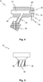
- FIG. 5 shows a side view of an embodiment of a thread exit element 19.
- This thread exit element 19 is provided with air guide elements 32. If compressed air is now blown between the thread outlet element 19 and the draw-off tube 18, an air vortex is generated in the compressed air flow by the air guide elements 32. With the help of this vortex a twist, usually a Z-twist, is generated in the thread or the twist is retained in the thread and does not dissolve.
- the air guiding elements 32 can also be assigned to the draw-off tube 18, or partially to the thread outlet element 19 and partially to the draw-off tube 18.
- FIGS 6a, 6b and 6c show cross sections of different thread guide units 6, the cross sections being in the region of the mouth 23.
- the mouth 23 is annular. This ensures an even flow of compressed air around the thread and is particularly gentle on the thread.
- Figure 6b shows a semicircular mouth 23.
- a mouth 23 is used in particular when, for example, a certain direction of the thread is predetermined by a kink 26 in the draw-off tube 18 and the compressed air flow is intended to guide the thread in this direction.
- FIG. 6c a mouth 23 in which a plurality of openings 33 are arranged along a ring, of which only two are provided with a reference symbol for the sake of clarity.
- Such a design of the mouth 23 offers increased stability of the thread guide unit 6 in the area of the mouth 23.
- Figure 7 a cross-section through a further thread guide unit 6.
- the compressed air nozzle 21 opens directly into the mouth 23.
- the compressed air nozzle 21 is offset from the axis of the draw-off tube 18 and the thread outlet element 19 and thus with a component tangential to the mouth 23.
- This offset arrangement of the compressed air nozzle 21 gives the blown air a tangential component, so that an air vortex is also generated here, with the advantages described above. It is also a combination of the tangential Compressed air nozzle with air guiding elements arranged at the mouth is conceivable, so that an air vortex of the correct strength is generated.
- FIG. 8 a cross section through a further thread guide unit 6.
- This thread guide unit 6 has an annular air chamber 22 in addition to the mouth 23.
- the compressed air nozzle 21 is similar to the embodiment of FIG Figure 7 , offset to the axis of the draw-off tube 18, the thread outlet element 19 and the annular air chamber 22 and thus has a component tangential to the mouth 23.
- the blown-in air receives a tangential component due to the offset arrangement of the compressed air nozzle 21. This also creates an air vortex, with the advantages described above.
Claims (17)
- Unité guide-fil destinée à tirer un fil (4) hors d'un rotor (2) d'un poste de filage (1) d'un métier à filer à bout libre, comprenant un tube d'extraction (18) et une buse à air comprimé (21),
dans laquelle
un élément de sortie de fil (19) est présent et une bouche (23) de la buse à air comprimé (21) est réalisée sous la forme d'un interstice entre le tube d'extraction (18) et l'élément de sortie de fil (19) caractérisée en ce que la buse à air comprimé (21) est disposée avec une composante tangentielle par rapport à la bouche (23) et/ou des éléments de guidage d'air (32) se trouvent dans la zone de la bouche (23) pour générer un tourbillon d'air, les éléments de guidage d'air (32) étant associés au tube d'extraction (18) et/ou à l'élément de sortie de fil (19). - Unité guide-fil selon la revendication précédente, caractérisée en ce que la bouche (23) de la buse à air comprimé (21) est de forme annulaire ou en forme de demi-cercle, ou possède plusieurs ouvertures (33) qui sont disposées le long d'un anneau.
- Unité guide-fil selon l'une des revendications précédentes, caractérisée en ce qu'un raccord à air comprimé (20 ; 24), notamment un couplage à air comprimé (24), est présent pour le raccordement d'un tuyau à air comprimé.
- Unité guide-fil selon l'une des revendications précédentes, caractérisée en ce qu'une chambre à air (22), notamment de forme annulaire, est formée entre le tube d'extraction (18) et l'élément de sortie de fil (19) et/ou l'élément de sortie de fil (19) est relié au tube d'extraction (18) par collage, soudage, vissage et/ou pressage.
- Unité guide-fil selon l'une des revendications précédentes, caractérisée en ce que le tube d'extraction (18) possède un changement de direction, notamment sous la forme d'un coude (26), de sorte que la direction de la partie du tube d'extraction (18) au niveau de laquelle est disposé l'élément de sortie de fil (19) correspond à un angle d'extraction du fil (4).
- Unité guide-fil selon l'une des revendications précédentes, caractérisée en ce que le tube d'extraction (18) possède un moyen d'arrêt de torsion (27) et/ou au moins un capteur de fil (28).
- Unité guide-fil selon l'une des revendications précédentes, caractérisée en ce qu'un moyen de fixation (7) destiné à fixer l'unité guide-fil (6) au poste de filage (1) est présent et/ou un raccord de dépression (25) se trouve au niveau de l'unité guide-fil (6).
- Unité guide-fil selon l'une des revendications précédentes, caractérisée en ce que le tube d'extraction (18) possède un diamètre intérieur (D) qui est compris entre 2 mm et 4 mm, de préférence entre 2,5 mm et 3,5 mm et notamment de préférence égal à environ 3 mm et/ou l'interstice de la bouche (23) possède une épaisseur (T) qui est comprise entre 0,5 % et 15 %, de préférence entre 1,5 % et 8 % et notamment de préférence égale à environ 3,5 % du diamètre intérieur (D) du tube d'extraction (18).
- Métier à filer à bout libre, comprenant une pluralité de postes de filage (1), chaque poste de filage (1) possédant un groupe de filage (3), une unité guide-fil (6), des cylindres d'extraction (5), une unité de bobinage (9, 11) et une unité d'application de fil (15, 14, 16),
caractérisé en ce que l'unité guide-fil (6) est configurée selon l'une des revendications précédentes. - Procédé pour faire fonctionner un poste de filage (1) d'un métier à filer à bout libre, un groupe de filage (3) produisant un fil (4), le fil (4) étant dévidé des cylindres d'extraction (5) par l'unité guide-fil (6) et enroulé sur une bobine (10) par une unité de bobinage (9, 11) et ensuite, lorsque le fil (4) doit être appliqué, une unité d'application de fil (15, 14, 16) déplace une extrémité de fil (17) vers l'unité guide-fil (6), où l'extrémité de fil (17) est tout d'abord aspirée dans l'unité guide-fil (6) et ensuite dans le groupe de filage (3) par une dépression qui règne dans le groupe de filage (3),
procédé selon lequel
un flux d'air comprimé, lequel sort notamment d'une buse à air comprimé (21) de l'unité guide-fil (6), assiste l'aspiration de l'extrémité de fil (17) dans le groupe de filage (3), de manière coordonnée dans le temps avec l'application du fil (4),
caractérisé en ce que
l'unité guide-fil (6) est réalisée selon l'une des revendications 1 à 6 et le flux d'air comprimé génère un tourbillon d'air, lequel produit et/ou renforce de préférence une torsion, notamment une torsion en Z, dans le fil (4) et/ou cause une fausse torsion dans le fil (4) pendant le dévidage du fil filé (4) à travers le tube d'extraction (18). - Procédé selon la
revendication précédente, caractérisé en ce
que la torsion dans le fil (4) est une torsion en Z. - Procédé selon la revendication 10 ou 11, caractérisé en ce qu'un flux d'air comprimé supplémentaire, lequel émane notamment de la buse à air comprimé (21) de l'unité guide-fil (6), assiste l'aspiration de l'extrémité de fil (17) dans l'unité guide-fil (6).
- Procédé selon l'une des revendications 10 à 12, caractérisé en ce que l'extrémité de fil (17), après qu'elle ait été aspirée dans l'unité guide-fil (6) et dans le groupe de filage (3), est préparée au niveau du bord d'un rotor (2) du groupe de filage (3) et un flux d'air comprimé est soufflé à travers la buse à air comprimé (21) de préférence pendant l'aspiration et/ou la préparation du fil et/ou l'extrémité de fil (17) est rétractée après qu'elle ait été préparée au niveau du bord du rotor (2).
- Procédé selon l'une des revendications 10 à 13, caractérisé en ce que l'extrémité de fil (17) est préparée à la main en-dehors de l'unité guide-fil (6) et/ou est préparée dans un groupe de préparation d'extrémité de fil (30), le groupe de préparation d'extrémité de fil (30) étant associé à une unité de maintenance mobile du métier à filer à bout libre et/ou étant associé au poste de filage (1) et se trouvant de préférence dans un bras latéral (29) du tube d'extraction (18).
- Procédé selon l'une des revendications 10 à 14, caractérisé en ce que l'aspiration de l'extrémité de fil (17) dans le groupe de filage (3), notamment après que l'extrémité de fil (17) ait été rétractée, est rendue possible par la rotation d'un moteur pas à pas réversible et/ou par le déliage d'une boucle, moyennant quoi l'extrémité de fil (17) est transportée sur un trajet prédéterminé dans le groupe de filage (3).
- Procédé selon l'une des revendications 10 à 15, caractérisé en ce que la position de l'extrémité de fil (17) est détectée au moyen d'au moins un capteur (28) dans un tube d'extraction (18) associé à l'unité guide-fil (6) et le flux d'air comprimé est de préférence commandé en tenant compte de la position de l'extrémité de fil (17).
- Procédé selon l'une des revendications 10 à 16, caractérisé en ce qu'un flux d'air comprimé est soufflé à intervalles temporels à travers la buse à air comprimé (21) en vue de nettoyer l'unité guide-fil (6) et/ou le groupe de filage (3).
Applications Claiming Priority (1)
| Application Number | Priority Date | Filing Date | Title |
|---|---|---|---|
| DE102016113963 | 2016-07-28 |
Publications (2)
| Publication Number | Publication Date |
|---|---|
| EP3276057A1 EP3276057A1 (fr) | 2018-01-31 |
| EP3276057B1 true EP3276057B1 (fr) | 2020-01-01 |
Family
ID=59409256
Family Applications (1)
| Application Number | Title | Priority Date | Filing Date |
|---|---|---|---|
| EP17183275.1A Active EP3276057B1 (fr) | 2016-07-28 | 2017-07-26 | Unité guide-fil, métier à filer à bout ouvert et procédé de fonctionnement d'un poste de filage |
Country Status (4)
| Country | Link |
|---|---|
| US (1) | US10689779B2 (fr) |
| EP (1) | EP3276057B1 (fr) |
| CN (1) | CN107663683B (fr) |
| DE (1) | DE102017116893A1 (fr) |
Families Citing this family (4)
| Publication number | Priority date | Publication date | Assignee | Title |
|---|---|---|---|---|
| CN109097875A (zh) * | 2018-08-31 | 2018-12-28 | 安徽日发纺织机械有限公司 | 一种转杯纺纱机自动接头方法 |
| DE102020101840A1 (de) | 2020-01-27 | 2021-07-29 | Maschinenfabrik Rieter Ag | Fadenführungseinheit, Offenend-Rotorspinnmaschine und Verfahren zum Betreiben einer Spinnstelle |
| EP4015682A1 (fr) * | 2020-12-18 | 2022-06-22 | Saurer Intelligent Technology AG | Poste de travail d'un métier à filer à jet d'air ainsi que élément de guidage de filetage |
| CN115467056B (zh) | 2021-06-10 | 2023-10-27 | 卓郎(江苏)纺织机械有限公司 | 用于自由端转杯纺纱装置的纺纱箱 |
Family Cites Families (30)
| Publication number | Priority date | Publication date | Assignee | Title |
|---|---|---|---|---|
| DE1062153B (de) * | 1957-01-29 | 1959-07-23 | Konrad Goetzfried | Pneumatische Spinnvorrichtung |
| DE1785158C3 (de) * | 1968-08-17 | 1979-05-17 | Metallgesellschaft Ag, 6000 Frankfurt | Runddiise zum Abziehen und Ablegen von Fäden zu einem Fadenvlies |
| DE2534816C3 (de) * | 1975-08-05 | 1979-12-20 | Zinser Textilmaschinen Gmbh, 7333 Ebersbach | OE-Spinnmaschine |
| US4030280A (en) * | 1976-01-07 | 1977-06-21 | The United States Of America As Represented By The Secretary Of Agriculture | Fiber blending, subdividing, and distributing system |
| US4114356A (en) * | 1976-08-05 | 1978-09-19 | Zinser Textilmaschinen Gmbh | Open-end spinning apparatus |
| CS199077B1 (en) * | 1977-08-17 | 1980-07-31 | Eduard Pallay | Method of and apparatus for manufacturing yarn from staple fibres in air vortex in a spinning tube |
| US4319448A (en) * | 1979-04-13 | 1982-03-16 | Instytut Wlokiennictwa | Process and apparatus for producing yarn |
| US4322942A (en) * | 1980-07-29 | 1982-04-06 | Vyzkumny Ustav Bavlnarsky | Open-end spinning method and apparatus |
| CS232869B1 (en) * | 1982-12-21 | 1985-02-14 | Stanislav Didek | Method of yarn spinning from staple fibres in air swirl and equipment for application of this method |
| EP0220546A1 (fr) * | 1985-10-15 | 1987-05-06 | Maschinenfabrik Rieter Ag | Dispositif de filature à bout libre |
| JPS6385123A (ja) * | 1986-09-22 | 1988-04-15 | Murata Mach Ltd | 紡績糸の製造方法及び製造装置 |
| US5718110A (en) * | 1993-02-12 | 1998-02-17 | Novibra Gmbh | Arrangement for open-end rotor spinning |
| JP2708000B2 (ja) * | 1995-02-10 | 1998-02-04 | 村田機械株式会社 | 紡績装置 |
| JP3132343B2 (ja) * | 1995-07-11 | 2001-02-05 | 株式会社豊田自動織機製作所 | ロータ式オープンエンド精紡機の糸継ぎ方法及び装置 |
| DE19624537A1 (de) * | 1996-06-20 | 1998-01-02 | Schlafhorst & Co W | Verfahren und Vorrichtung zum Anspinnen eines Fadenendes in einer Offenend-Spinnvorrichtung |
| JP3064951B2 (ja) * | 1997-04-24 | 2000-07-12 | 村田機械株式会社 | 糸通し装置 |
| DE19718768A1 (de) * | 1997-05-05 | 1998-11-12 | Rieter Ingolstadt Spinnerei | Verfahren und Vorrichtung zum pneumatischen Reinigen eines Fadenabzugsrohres |
| DE10139072B4 (de) * | 2001-08-09 | 2009-12-17 | Oerlikon Textile Gmbh & Co. Kg | Serviceaggregat zum Wiederanspinnen von Arbeitsstellen einer Offenend-Spinnmaschine |
| DE102005022187A1 (de) * | 2005-05-13 | 2006-11-16 | Saurer Gmbh & Co. Kg | Anspinnverfahren an einer Luftspinnmaschine sowie Spinnvorrichtung und Luftspinnmaschine |
| DE102005045703A1 (de) * | 2005-09-19 | 2007-03-22 | Wilhelm Stahlecker Gmbh | Luftdüsenaggregat für eine Luftdüsenspinnvorrichtung |
| EP2767625B1 (fr) * | 2013-02-13 | 2017-01-11 | Maschinenfabrik Rieter Ag | Poste de filage d'un métier à filer |
| DE102013101988A1 (de) * | 2013-02-28 | 2014-08-28 | Maschinenfabrik Rieter Ag | Spinnstelle zur Herstellung eines Garns |
| CH708164A1 (de) * | 2013-06-14 | 2014-12-15 | Rieter Ag Maschf | Spinndüse sowie damit ausgerüstete Spinnstelle einer Luftspinnmaschine. |
| CN203440530U (zh) * | 2013-08-07 | 2014-02-19 | 经纬纺织机械股份有限公司 | 一种转杯纺纱机降速接头控制装置 |
| DE102014103193A1 (de) * | 2014-03-11 | 2015-09-17 | Rieter Ingolstadt Gmbh | Spinnmaschine und Verfahren zum Übergeben eines Garnes an eine Anspinnvorrichtung |
| CN103924333B (zh) * | 2014-04-17 | 2016-02-03 | 江阴市华方新技术科研有限公司 | 一种纱线导引装置 |
| CZ2014329A3 (cs) * | 2014-05-13 | 2015-11-25 | Rieter Cz S.R.O. | Způsob individuálního zapřádání příze na pracovním místě rotorového dopřádacího stroje |
| CH709748A1 (de) * | 2014-06-12 | 2015-12-15 | Rieter Ag Maschf | Luftspinnmaschine sowie Verfahren zum Betrieb einer solchen. |
| CH709953A1 (de) * | 2014-07-30 | 2016-02-15 | Rieter Ag Maschf | Verfahren zum Betrieb einer Luftspinnmaschine. |
| ITUA20163006A1 (it) * | 2016-04-29 | 2017-10-29 | Savio Macch Tessili Spa | Dispositivo di filatura di tipo air-jet |
-
2017
- 2017-07-26 EP EP17183275.1A patent/EP3276057B1/fr active Active
- 2017-07-26 DE DE102017116893.1A patent/DE102017116893A1/de not_active Withdrawn
- 2017-07-27 US US15/661,659 patent/US10689779B2/en active Active
- 2017-07-27 CN CN201710626331.XA patent/CN107663683B/zh active Active
Non-Patent Citations (1)
| Title |
|---|
| None * |
Also Published As
| Publication number | Publication date |
|---|---|
| CN107663683B (zh) | 2022-06-07 |
| US20180030624A1 (en) | 2018-02-01 |
| CN107663683A (zh) | 2018-02-06 |
| EP3276057A1 (fr) | 2018-01-31 |
| DE102017116893A1 (de) | 2018-02-01 |
| US10689779B2 (en) | 2020-06-23 |
Similar Documents
| Publication | Publication Date | Title |
|---|---|---|
| DE60110981T2 (de) | Maschine und Verfahren zur Herstellung eines Kerngarnes | |
| DE19501545C2 (de) | Verfahren zum Andrehen eines Garnes in einer Spinnmaschine | |
| DE3706728C2 (fr) | ||
| EP3652368B1 (fr) | Procédé pour faire fonctionner un arrangement de filage à jet d'air | |
| EP3276057B1 (fr) | Unité guide-fil, métier à filer à bout ouvert et procédé de fonctionnement d'un poste de filage | |
| EP2679711B1 (fr) | Métier à tisser à jet d'air et procédé destiné au rattachement d'un fil | |
| EP2726655B1 (fr) | Banc à broches destiné à fabriquer une mèche et procédé permettant de commencer à filer un assemblage de fibres | |
| DE60009402T2 (de) | Spinnvorrichtung und Spinnverfahren | |
| EP3148913B1 (fr) | Procédé permettant de faire fonctionner une machine textile et machine textile servant à produire une mèche | |
| DE102005022187A1 (de) | Anspinnverfahren an einer Luftspinnmaschine sowie Spinnvorrichtung und Luftspinnmaschine | |
| DE60120082T3 (de) | Spinnvorrichtung | |
| WO2008095631A1 (fr) | Dispositif de filage à air | |
| WO1987003310A1 (fr) | Procede et dispositif de renfilage d'un dispositif a filer pourvu d'un organe tordeur pneumatique | |
| DE60103721T2 (de) | Anspinnverfahren und Anspinnvorrichtung für eine Spinnmaschine | |
| EP0162367B2 (fr) | Procédé et dispositif pour la préparation de l'extrémité de fil pour la remise en route d'une machine à bout libéré | |
| DE102005031279A1 (de) | Fadenabsaugvorrichtung | |
| DE3410471A1 (de) | Oe-friktionsspinnmaschine mit einer vielzahl von spinnaggregaten und einem verfahrbaren wartungsgeraet | |
| DE102006018242A1 (de) | Luftdüsenspinnvorrichtung | |
| EP3140233B1 (fr) | Machine textile pour la production d'une meche et procede de demarrage d'une telle machine pour produire une meche | |
| EP1295974A2 (fr) | Métier à filer à jet d'air avec un dispositif défibreur | |
| EP4050138B1 (fr) | Procédé de fonctionnement d'un poste de travail d'un métier à filer et poste de travail | |
| DE10141965A1 (de) | Verfahren zum Handhaben einer Spinnvorrichtung | |
| DE3908463A1 (de) | Vorrichtung zum zwischenspeichern eines doppelfadens | |
| DE102004006709A1 (de) | Verfahren zum Vorbereiten eines Ansetzvorganges an einer Luftdüsenspinnvorrichtung | |
| EP3854917A1 (fr) | Unité de guidage de fil, métier à filer à rotor à bout libre et procédé de fonctionnement d'un poste de filage |
Legal Events
| Date | Code | Title | Description |
|---|---|---|---|
| PUAI | Public reference made under article 153(3) epc to a published international application that has entered the european phase |
Free format text: ORIGINAL CODE: 0009012 |
|
| STAA | Information on the status of an ep patent application or granted ep patent |
Free format text: STATUS: THE APPLICATION HAS BEEN PUBLISHED |
|
| AK | Designated contracting states |
Kind code of ref document: A1 Designated state(s): AL AT BE BG CH CY CZ DE DK EE ES FI FR GB GR HR HU IE IS IT LI LT LU LV MC MK MT NL NO PL PT RO RS SE SI SK SM TR |
|
| AX | Request for extension of the european patent |
Extension state: BA ME |
|
| STAA | Information on the status of an ep patent application or granted ep patent |
Free format text: STATUS: REQUEST FOR EXAMINATION WAS MADE |
|
| 17P | Request for examination filed |
Effective date: 20180730 |
|
| RBV | Designated contracting states (corrected) |
Designated state(s): AL AT BE BG CH CY CZ DE DK EE ES FI FR GB GR HR HU IE IS IT LI LT LU LV MC MK MT NL NO PL PT RO RS SE SI SK SM TR |
|
| GRAP | Despatch of communication of intention to grant a patent |
Free format text: ORIGINAL CODE: EPIDOSNIGR1 |
|
| STAA | Information on the status of an ep patent application or granted ep patent |
Free format text: STATUS: GRANT OF PATENT IS INTENDED |
|
| INTG | Intention to grant announced |
Effective date: 20190917 |
|
| GRAS | Grant fee paid |
Free format text: ORIGINAL CODE: EPIDOSNIGR3 |
|
| GRAA | (expected) grant |
Free format text: ORIGINAL CODE: 0009210 |
|
| STAA | Information on the status of an ep patent application or granted ep patent |
Free format text: STATUS: THE PATENT HAS BEEN GRANTED |
|
| AK | Designated contracting states |
Kind code of ref document: B1 Designated state(s): AL AT BE BG CH CY CZ DE DK EE ES FI FR GB GR HR HU IE IS IT LI LT LU LV MC MK MT NL NO PL PT RO RS SE SI SK SM TR |
|
| REG | Reference to a national code |
Ref country code: GB Ref legal event code: FG4D Free format text: NOT ENGLISH |
|
| REG | Reference to a national code |
Ref country code: CH Ref legal event code: EP Ref country code: AT Ref legal event code: REF Ref document number: 1219883 Country of ref document: AT Kind code of ref document: T Effective date: 20200115 |
|
| REG | Reference to a national code |
Ref country code: IE Ref legal event code: FG4D Free format text: LANGUAGE OF EP DOCUMENT: GERMAN |
|
| REG | Reference to a national code |
Ref country code: DE Ref legal event code: R096 Ref document number: 502017003329 Country of ref document: DE |
|
| REG | Reference to a national code |
Ref country code: NL Ref legal event code: MP Effective date: 20200101 |
|
| REG | Reference to a national code |
Ref country code: LT Ref legal event code: MG4D |
|
| PG25 | Lapsed in a contracting state [announced via postgrant information from national office to epo] |
Ref country code: PT Free format text: LAPSE BECAUSE OF FAILURE TO SUBMIT A TRANSLATION OF THE DESCRIPTION OR TO PAY THE FEE WITHIN THE PRESCRIBED TIME-LIMIT Effective date: 20200527 Ref country code: CZ Free format text: LAPSE BECAUSE OF FAILURE TO SUBMIT A TRANSLATION OF THE DESCRIPTION OR TO PAY THE FEE WITHIN THE PRESCRIBED TIME-LIMIT Effective date: 20200101 Ref country code: NO Free format text: LAPSE BECAUSE OF FAILURE TO SUBMIT A TRANSLATION OF THE DESCRIPTION OR TO PAY THE FEE WITHIN THE PRESCRIBED TIME-LIMIT Effective date: 20200401 Ref country code: NL Free format text: LAPSE BECAUSE OF FAILURE TO SUBMIT A TRANSLATION OF THE DESCRIPTION OR TO PAY THE FEE WITHIN THE PRESCRIBED TIME-LIMIT Effective date: 20200101 Ref country code: RS Free format text: LAPSE BECAUSE OF FAILURE TO SUBMIT A TRANSLATION OF THE DESCRIPTION OR TO PAY THE FEE WITHIN THE PRESCRIBED TIME-LIMIT Effective date: 20200101 Ref country code: LT Free format text: LAPSE BECAUSE OF FAILURE TO SUBMIT A TRANSLATION OF THE DESCRIPTION OR TO PAY THE FEE WITHIN THE PRESCRIBED TIME-LIMIT Effective date: 20200101 Ref country code: FI Free format text: LAPSE BECAUSE OF FAILURE TO SUBMIT A TRANSLATION OF THE DESCRIPTION OR TO PAY THE FEE WITHIN THE PRESCRIBED TIME-LIMIT Effective date: 20200101 |
|
| PG25 | Lapsed in a contracting state [announced via postgrant information from national office to epo] |
Ref country code: BG Free format text: LAPSE BECAUSE OF FAILURE TO SUBMIT A TRANSLATION OF THE DESCRIPTION OR TO PAY THE FEE WITHIN THE PRESCRIBED TIME-LIMIT Effective date: 20200401 Ref country code: IS Free format text: LAPSE BECAUSE OF FAILURE TO SUBMIT A TRANSLATION OF THE DESCRIPTION OR TO PAY THE FEE WITHIN THE PRESCRIBED TIME-LIMIT Effective date: 20200501 Ref country code: GR Free format text: LAPSE BECAUSE OF FAILURE TO SUBMIT A TRANSLATION OF THE DESCRIPTION OR TO PAY THE FEE WITHIN THE PRESCRIBED TIME-LIMIT Effective date: 20200402 Ref country code: HR Free format text: LAPSE BECAUSE OF FAILURE TO SUBMIT A TRANSLATION OF THE DESCRIPTION OR TO PAY THE FEE WITHIN THE PRESCRIBED TIME-LIMIT Effective date: 20200101 Ref country code: LV Free format text: LAPSE BECAUSE OF FAILURE TO SUBMIT A TRANSLATION OF THE DESCRIPTION OR TO PAY THE FEE WITHIN THE PRESCRIBED TIME-LIMIT Effective date: 20200101 Ref country code: SE Free format text: LAPSE BECAUSE OF FAILURE TO SUBMIT A TRANSLATION OF THE DESCRIPTION OR TO PAY THE FEE WITHIN THE PRESCRIBED TIME-LIMIT Effective date: 20200101 |
|
| REG | Reference to a national code |
Ref country code: DE Ref legal event code: R097 Ref document number: 502017003329 Country of ref document: DE |
|
| PG25 | Lapsed in a contracting state [announced via postgrant information from national office to epo] |
Ref country code: ES Free format text: LAPSE BECAUSE OF FAILURE TO SUBMIT A TRANSLATION OF THE DESCRIPTION OR TO PAY THE FEE WITHIN THE PRESCRIBED TIME-LIMIT Effective date: 20200101 Ref country code: RO Free format text: LAPSE BECAUSE OF FAILURE TO SUBMIT A TRANSLATION OF THE DESCRIPTION OR TO PAY THE FEE WITHIN THE PRESCRIBED TIME-LIMIT Effective date: 20200101 Ref country code: SK Free format text: LAPSE BECAUSE OF FAILURE TO SUBMIT A TRANSLATION OF THE DESCRIPTION OR TO PAY THE FEE WITHIN THE PRESCRIBED TIME-LIMIT Effective date: 20200101 Ref country code: EE Free format text: LAPSE BECAUSE OF FAILURE TO SUBMIT A TRANSLATION OF THE DESCRIPTION OR TO PAY THE FEE WITHIN THE PRESCRIBED TIME-LIMIT Effective date: 20200101 Ref country code: SM Free format text: LAPSE BECAUSE OF FAILURE TO SUBMIT A TRANSLATION OF THE DESCRIPTION OR TO PAY THE FEE WITHIN THE PRESCRIBED TIME-LIMIT Effective date: 20200101 Ref country code: DK Free format text: LAPSE BECAUSE OF FAILURE TO SUBMIT A TRANSLATION OF THE DESCRIPTION OR TO PAY THE FEE WITHIN THE PRESCRIBED TIME-LIMIT Effective date: 20200101 |
|
| PLBE | No opposition filed within time limit |
Free format text: ORIGINAL CODE: 0009261 |
|
| STAA | Information on the status of an ep patent application or granted ep patent |
Free format text: STATUS: NO OPPOSITION FILED WITHIN TIME LIMIT |
|
| 26N | No opposition filed |
Effective date: 20201002 |
|
| PG25 | Lapsed in a contracting state [announced via postgrant information from national office to epo] |
Ref country code: MC Free format text: LAPSE BECAUSE OF FAILURE TO SUBMIT A TRANSLATION OF THE DESCRIPTION OR TO PAY THE FEE WITHIN THE PRESCRIBED TIME-LIMIT Effective date: 20200101 Ref country code: SI Free format text: LAPSE BECAUSE OF FAILURE TO SUBMIT A TRANSLATION OF THE DESCRIPTION OR TO PAY THE FEE WITHIN THE PRESCRIBED TIME-LIMIT Effective date: 20200101 Ref country code: PL Free format text: LAPSE BECAUSE OF FAILURE TO SUBMIT A TRANSLATION OF THE DESCRIPTION OR TO PAY THE FEE WITHIN THE PRESCRIBED TIME-LIMIT Effective date: 20200101 |
|
| REG | Reference to a national code |
Ref country code: CH Ref legal event code: PL |
|
| REG | Reference to a national code |
Ref country code: BE Ref legal event code: MM Effective date: 20200731 |
|
| PG25 | Lapsed in a contracting state [announced via postgrant information from national office to epo] |
Ref country code: LU Free format text: LAPSE BECAUSE OF NON-PAYMENT OF DUE FEES Effective date: 20200726 Ref country code: CH Free format text: LAPSE BECAUSE OF NON-PAYMENT OF DUE FEES Effective date: 20200731 Ref country code: LI Free format text: LAPSE BECAUSE OF NON-PAYMENT OF DUE FEES Effective date: 20200731 Ref country code: FR Free format text: LAPSE BECAUSE OF NON-PAYMENT OF DUE FEES Effective date: 20200731 |
|
| PG25 | Lapsed in a contracting state [announced via postgrant information from national office to epo] |
Ref country code: BE Free format text: LAPSE BECAUSE OF NON-PAYMENT OF DUE FEES Effective date: 20200731 |
|
| PG25 | Lapsed in a contracting state [announced via postgrant information from national office to epo] |
Ref country code: IE Free format text: LAPSE BECAUSE OF NON-PAYMENT OF DUE FEES Effective date: 20200726 |
|
| GBPC | Gb: european patent ceased through non-payment of renewal fee |
Effective date: 20210726 |
|
| PG25 | Lapsed in a contracting state [announced via postgrant information from national office to epo] |
Ref country code: GB Free format text: LAPSE BECAUSE OF NON-PAYMENT OF DUE FEES Effective date: 20210726 |
|
| PG25 | Lapsed in a contracting state [announced via postgrant information from national office to epo] |
Ref country code: MT Free format text: LAPSE BECAUSE OF FAILURE TO SUBMIT A TRANSLATION OF THE DESCRIPTION OR TO PAY THE FEE WITHIN THE PRESCRIBED TIME-LIMIT Effective date: 20200101 Ref country code: CY Free format text: LAPSE BECAUSE OF FAILURE TO SUBMIT A TRANSLATION OF THE DESCRIPTION OR TO PAY THE FEE WITHIN THE PRESCRIBED TIME-LIMIT Effective date: 20200101 |
|
| PG25 | Lapsed in a contracting state [announced via postgrant information from national office to epo] |
Ref country code: MK Free format text: LAPSE BECAUSE OF FAILURE TO SUBMIT A TRANSLATION OF THE DESCRIPTION OR TO PAY THE FEE WITHIN THE PRESCRIBED TIME-LIMIT Effective date: 20200101 Ref country code: AL Free format text: LAPSE BECAUSE OF FAILURE TO SUBMIT A TRANSLATION OF THE DESCRIPTION OR TO PAY THE FEE WITHIN THE PRESCRIBED TIME-LIMIT Effective date: 20200101 |
|
| P01 | Opt-out of the competence of the unified patent court (upc) registered |
Effective date: 20230329 |
|
| REG | Reference to a national code |
Ref country code: AT Ref legal event code: MM01 Ref document number: 1219883 Country of ref document: AT Kind code of ref document: T Effective date: 20220726 |
|
| PG25 | Lapsed in a contracting state [announced via postgrant information from national office to epo] |
Ref country code: AT Free format text: LAPSE BECAUSE OF NON-PAYMENT OF DUE FEES Effective date: 20220726 |
|
| PGFP | Annual fee paid to national office [announced via postgrant information from national office to epo] |
Ref country code: TR Payment date: 20230713 Year of fee payment: 7 Ref country code: IT Payment date: 20230727 Year of fee payment: 7 |
|
| PGFP | Annual fee paid to national office [announced via postgrant information from national office to epo] |
Ref country code: DE Payment date: 20230724 Year of fee payment: 7 |