EP3274277B1 - Vorrichtung zum transport eines modularen arbeitsplatzes und verfahren zum betrieb - Google Patents
Vorrichtung zum transport eines modularen arbeitsplatzes und verfahren zum betrieb Download PDFInfo
- Publication number
- EP3274277B1 EP3274277B1 EP15887928.8A EP15887928A EP3274277B1 EP 3274277 B1 EP3274277 B1 EP 3274277B1 EP 15887928 A EP15887928 A EP 15887928A EP 3274277 B1 EP3274277 B1 EP 3274277B1
- Authority
- EP
- European Patent Office
- Prior art keywords
- transport
- workpiece
- working area
- axial
- transport mechanism
- Prior art date
- Legal status (The legal status is an assumption and is not a legal conclusion. Google has not performed a legal analysis and makes no representation as to the accuracy of the status listed.)
- Active
Links
Images


Classifications
-
- B—PERFORMING OPERATIONS; TRANSPORTING
- B65—CONVEYING; PACKING; STORING; HANDLING THIN OR FILAMENTARY MATERIAL
- B65G—TRANSPORT OR STORAGE DEVICES, e.g. CONVEYORS FOR LOADING OR TIPPING, SHOP CONVEYOR SYSTEMS OR PNEUMATIC TUBE CONVEYORS
- B65G37/00—Combinations of mechanical conveyors of the same kind, or of different kinds, of interest apart from their application in particular machines or use in particular manufacturing processes
- B65G37/02—Flow-sheets for conveyor combinations in warehouses, magazines or workshops
-
- B—PERFORMING OPERATIONS; TRANSPORTING
- B65—CONVEYING; PACKING; STORING; HANDLING THIN OR FILAMENTARY MATERIAL
- B65G—TRANSPORT OR STORAGE DEVICES, e.g. CONVEYORS FOR LOADING OR TIPPING, SHOP CONVEYOR SYSTEMS OR PNEUMATIC TUBE CONVEYORS
- B65G15/00—Conveyors having endless load-conveying surfaces, i.e. belts and like continuous members, to which tractive effort is transmitted by means other than endless driving elements of similar configuration
-
- H—ELECTRICITY
- H01—ELECTRIC ELEMENTS
- H01L—SEMICONDUCTOR DEVICES NOT COVERED BY CLASS H10
- H01L21/00—Processes or apparatus adapted for the manufacture or treatment of semiconductor or solid state devices or of parts thereof
- H01L21/67—Apparatus specially adapted for handling semiconductor or electric solid state devices during manufacture or treatment thereof; Apparatus specially adapted for handling wafers during manufacture or treatment of semiconductor or electric solid state devices or components ; Apparatus not specifically provided for elsewhere
- H01L21/67005—Apparatus not specifically provided for elsewhere
- H01L21/67242—Apparatus for monitoring, sorting or marking
- H01L21/67276—Production flow monitoring, e.g. for increasing throughput
-
- H—ELECTRICITY
- H01—ELECTRIC ELEMENTS
- H01L—SEMICONDUCTOR DEVICES NOT COVERED BY CLASS H10
- H01L21/00—Processes or apparatus adapted for the manufacture or treatment of semiconductor or solid state devices or of parts thereof
- H01L21/67—Apparatus specially adapted for handling semiconductor or electric solid state devices during manufacture or treatment thereof; Apparatus specially adapted for handling wafers during manufacture or treatment of semiconductor or electric solid state devices or components ; Apparatus not specifically provided for elsewhere
- H01L21/677—Apparatus specially adapted for handling semiconductor or electric solid state devices during manufacture or treatment thereof; Apparatus specially adapted for handling wafers during manufacture or treatment of semiconductor or electric solid state devices or components ; Apparatus not specifically provided for elsewhere for conveying, e.g. between different workstations
- H01L21/67703—Apparatus specially adapted for handling semiconductor or electric solid state devices during manufacture or treatment thereof; Apparatus specially adapted for handling wafers during manufacture or treatment of semiconductor or electric solid state devices or components ; Apparatus not specifically provided for elsewhere for conveying, e.g. between different workstations between different workstations
- H01L21/67715—Changing the direction of the conveying path
-
- H—ELECTRICITY
- H01—ELECTRIC ELEMENTS
- H01L—SEMICONDUCTOR DEVICES NOT COVERED BY CLASS H10
- H01L21/00—Processes or apparatus adapted for the manufacture or treatment of semiconductor or solid state devices or of parts thereof
- H01L21/67—Apparatus specially adapted for handling semiconductor or electric solid state devices during manufacture or treatment thereof; Apparatus specially adapted for handling wafers during manufacture or treatment of semiconductor or electric solid state devices or components ; Apparatus not specifically provided for elsewhere
- H01L21/677—Apparatus specially adapted for handling semiconductor or electric solid state devices during manufacture or treatment thereof; Apparatus specially adapted for handling wafers during manufacture or treatment of semiconductor or electric solid state devices or components ; Apparatus not specifically provided for elsewhere for conveying, e.g. between different workstations
- H01L21/67703—Apparatus specially adapted for handling semiconductor or electric solid state devices during manufacture or treatment thereof; Apparatus specially adapted for handling wafers during manufacture or treatment of semiconductor or electric solid state devices or components ; Apparatus not specifically provided for elsewhere for conveying, e.g. between different workstations between different workstations
- H01L21/67736—Loading to or unloading from a conveyor
Definitions
- the invention relates to a modular workstation transport apparatus.
- the invention also relates to a series of modular workstation transport apparatus.
- the invention also relates to a method of transporting a workpiece using a modular workstation transport apparatus.
- the invention has particular, but not exclusive application in the transportation of workpieces such as semiconductor substrates particularly in manufacturing operations such as dispensing of, say, liquids like liquid adhesives, solder paste and encapsulation resin onto the substrate.
- An interface for transferring wafer carriers between a conveyor and a process chamber load location is provided.
- the interface has two portions.
- the first portion is configured so that a first wafer carrier moving along a wafer carrier transport mechanism (e.g., a conveyor) may travel therethrough.
- the second portion is configured so that a second wafer carrier contained within the second portion may index between a first position and a second position without obstructing passage of the first wafer carrier through the first portion.
- the interface contains an indexer/elevator that facilitates wafer carrier coupling and uncoupling from the conveyor, and facilitates wafer transfer to and from wafer handlers that load process chambers.
- US 2006/280588 A1 discloses a vacuum conveyor system for conveying a substrate that includes a vacuum sleeve and a plurality of rollers disposed within the vacuum sleeve for supporting and transporting the substrate thereupon.
- the plurality of rollers is adapted to simultaneously support the substrate thereupon at a plurality of elevations.
- a leading edge of the substrate is supported at an elevation above an adjacent one of the plurality of rollers in the direction of travel.
- the modular workstation transport apparatus has particular application in use with a workstation having machinery, such as robotic components, for performing operations on the workpiece at the station.
- the modular workstation transport apparatus can transport the workpiece to a working area of the modular workstation transport apparatus (or of the workstation) for operations to be conducted on the workpiece.
- Use of these techniques is not limited to operation with robotic machinery and, for example, the modular workstation transport apparatus can be arranged to transport the workpiece to a working area for a manual (human) operator to work thereon.
- a modular workstation transport apparatus is suitable for operation as one modular workstation transport apparatus in a series of modular workstation transport apparatus, where the workstation transport apparatus is configured for operation such that, after operation at the working area of that station, the workpiece can be transported downstream to, say, another modular workstation transport apparatus in the series using a first axial transport mechanism or it can be transported upstream to, say, an upstream modular workstation transport apparatus in the series using a second axial transport mechanism.
- the modular workstation transport apparatus as disclosed herein has the additional functionality in that when the workpiece is brought into the modular workstation transport apparatus, it need not necessarily be conveyed to a working area thereof, but can simply be held as "holding”, awaiting transportation to another modular workstation transport apparatus for operation thereat.
- the modular workstation transport apparatus is modular, this provides enormous flexibility in line setup. For instance, consider a scenario in which the series of modular workstations (each of which may or may not have associated workstations mentioned above) are provided in a series of Station A, Station B, Station C, Station D, from downstream to upstream, and the transport apparatus is such that the workpiece is fed sequentially from Station A, through Station B, Station C to Station D with manufacturing process operations to be conducted at some or all of the stations sequentially. If it is determined that, repetition of the process operation at Station B is required after operation at Station C, then the workpiece can be transported back upstream to Station B for operation thereat.
- the series of modular workstations each of which may or may not have associated workstations mentioned above
- the transport apparatus is such that the workpiece is fed sequentially from Station A, through Station B, Station C to Station D with manufacturing process operations to be conducted at some or all of the stations sequentially. If it is determined that, repetition of the process operation at Station B is required after operation at Station C, then the workpiece can
- implementation of the techniques disclosed herein may provide significant technical benefits in manufacturing processes, allowing hitherto unknown flexibility to addressing manufacturing issues such as catering for new processes and line balancing and the like.
- one of the modular workstations to be set up as a "master", and for the remaining workstations in the series to be designated as slaves, operating under control of the master station.
- the capability to program the transport of the product between the work stations may be required only in the master machine, e.g. the first workstation in the series. This may result in significant savings.
- the main machine (Master) can be linked up with any number of secondary machines (Slaves).
- the programmable logic controller (PLC) mounted on the master machine communicates with the secondary/slave machines to control the routing of workpieces through the system.
- Each modular transport can work with another so that it can be arranged in individual, progressive or mixed individual/progressive mode.
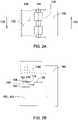
- a modular workstation transport apparatus 100 is illustrated in perspective view.
- modular workstation transport apparatus 100 is located adjacent to workstation 102.
- modular workstation transport apparatus 100 and workstation 102 are designed for co-operation with one another.
- transport apparatus 100 and workstation 102 are separate, free-standing modules, brought together so that they may co-operate closely with one another.
- the workstation cell is not free-standing, but arranged for mounting on or in a frame or housing of the transport apparatus 100.
- Modular workstation transport apparatus 100 is configured to transport a workpiece (not shown in this figure) to a working area for machinery - such as robotic machinery components - in workstation 102 to operate on the workpiece while it is at the working area.
- machinery - such as robotic machinery components - in workstation 102
- Modular workstation transport apparatus 100 has a housing 104 defining an internal volume or "envelope" of the modular workstation transport apparatus.
- the housing 104 need not be made up of a single part, or of parts of identical construction.
- housing 104 is made up at least in part of sheet metal. It may be advantageous if the housing is a full steel structure with sheet metal panel.
- the housing is not necessary for the housing 104 to enclose completely the modular workstation transport apparatus 100, and there may be one or more openings in the housing providing access to internal components, or for other purposes such as ventilation. Indeed, as will be described below, it may be possible for components of at least one of the axial transport systems to move outside of the envelope defined by the housing.
- Figure 2 provides schematic block diagrams of the modular workstation transport apparatus 100 and the workstation 102, including schematic representations of some of the internal component systems.
- Figure 2A is a schematic plan view
- Figure 2B is a schematic cross-section elevational view.
- workstation 102 has a tooling gantry 106 for fixing of tooling components such as robotic components thereto, although these are omitted from Figure 2 for clarity.
- tooling components such as robotic components
- Workpiece 108 is illustrated at working area generally denoted 110 where the tooling components hanging from or affixed to gantry 106 may operate/work on the workpiece 108.
- the workpiece 108 may be operated on in any number of ways. For instance, components (not illustrated) may be disposed upon upper surface 112 of the workpiece by the tooling components and/or any components already positioned thereon may be operated on by the tooling components.
- Other types of operations on the workpiece 108 are embraced, including dispensing of liquids, such as liquid adhesives and the like.
- Workpiece 108 is supported at the working area 110 on its underside 114, although the support is omitted from Figure 2 for the sake of clarity.
- workpiece 108 is of generally rectangular shape having long edges 116 and short edges 118.
- Modular workstation transport apparatus 100 also comprises a first axial transport mechanism 120 and a second axial transport mechanism 122.
- First axial transport mechanism 120 is arranged to transport workpieces being received in this example from the bottom as shown in the plan view of Figure 2A along a first axis (or line) 124 of the apparatus in a downstream direction 126, which may be considered as a supply direction.
- Second axial transport mechanism 122 is arranged to transport workpieces along a second axis (or line) 128 of the apparatus in an upstream direction 130, which may be considered as a return direction.
- a first workpiece area transport mechanism (omitted from Figures 2A and 2B , but illustrated in Figure 2C and as described in more detail with respect to Figure 4 ) transports the workpiece between the first axial transport mechanism 120 and the working area 110.
- a second working area transport mechanism (also omitted from Figures 2A and 2B , but illustrated in Figure 2C and as described in more detail with reference to Figure 5 ) transports the workpiece between the second axial transport mechanism 122 and the working area 110.
- workpieces may be received at the modular workstation transport apparatus 100 from either the upstream or downstream direction, and transported to or from the working area 110.
- the workpiece can be conveyed onwards to the next modular workstation in the series of modular workstations in either the downstream or upstream direction.
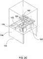
- Figure 2C illustrates a perspective view of the modular workstation transport apparatus 100 and its main components: the first axial transport mechanism 120 described in more detail with reference to Figure 3 ; the second axial transport mechanism 122 described in more detail with reference to Figure 5 ; the first working area transport mechanism 162 described in more detail with reference to Figure 4 ; and the second working area transport mechanism 183, also described in more detail with reference to Figure 4 .
- Figures 1 and 2 illustrate a modular workstation transport apparatus 100 (optionally operable as one modular workstation transport apparatus in a series of modular workstation transport apparatus), the modular workstation transport apparatus 100 comprising: a first axial transport mechanism 120 for transporting a workpiece 108 along a first axial direction 126.
- a second axial transport mechanism 122 transports the workpiece 110 along a second axial direction 130.
- a first working area transport mechanism 162 transports the workpiece 108 between a working area 110 and the first axial transport mechanism 120.
- a second working area transport 183 mechanism transports the workpiece 108 between the working area 110 and the second axial transport mechanism 122.
- axis or "axial” is not intended to suggest that the transportation of a workpiece within the modular workstation transport apparatus 100 must be along a straight line without departure therefrom (although such arrangements are of course embraced within the current techniques), but more to indicate simply that the workpieces are intended for transportation generally in directions along the axis or axes of the apparatus.
- first axial transport mechanism 120 comprises a first displacement mechanism generally referred to by 132 and a second displacement mechanism generally referred to by 134.
- first displacement mechanism 132, 134 while being part of the mechanism 120 provided to transport workpieces in axis 124, are also arranged to transport (i.e. displace) workpieces 108 into and out of the first axial transport system 120, as described in more detail with reference to Figure 4 below.
- First axial transport mechanism 120 also comprises a movable support structure 136 for the first and second displacement mechanisms moved under power of transport drive mechanism 137.
- first and second displacement mechanisms 132, 134 are able to move simultaneously along axis 124, due to their common mounting on movable support structure 136.
- the drive mechanism 137 is able to drive first and second displacement mechanisms 132, 134 along both the upstream and downstream directions 126, 130 in or along axis 124, but the general flow of workpiece components using first axial transport mechanism 120 is downstream in direction 126, as illustrated in Figure 2 , although transportation of workpieces in the reverse direction 130 is also possible using first axial transport mechanism 120.
- First displacement mechanism 132 comprises a first displacement platform 138 on which workpieces 108 may be disposed.
- First displacement mechanism 132 further comprises a first actuator mechanism 140 arranged to move first displacement platform 138 between a first proximal position 142 and a first distal position 144.
- the first proximal position 142 is a position closer to movable support structure 136 than the first distal position 144.
- distal position 144 is a raised position and proximal position 142 is a lowered position, at a lower elevation than distal position 144.
- Second displacement mechanism 134 comprises a first displacement platform 138 on which workpieces 108 may be disposed. Second displacement mechanism 134 further comprises a second actuator mechanism 148 arranged to move second displacement platform 146 between a second proximal position 150 and a second distal position 152.
- the second proximal position 150 is a position closer to movable support structure 136 than the second distal position 152.
- distal position 152 is a raised position and proximal position 150 is a lowered position, at a lower elevation than distal position 152.
- Displacement mechanisms 132, 134 may be arranged for the transfer of workpieces 108 to and/or from first working area transport mechanism 162 or a holding area or jig 103 in Figure 2C , where it is desired for the workpiece 108 simply to be held for a time according to the specified manufacturing process as the first and second actuator mechanisms 140, 148 move platforms 138, 146 between respective proximal and distal positions, as will be described in more detail below with respect to Figure 4 .
- the first axial transport mechanism 120 may be arranged such that at least part of the mechanism can be disposed (for example moved to) outside of the envelope of the modular workstation transport apparatus 100, defined by housing 104.
- at least part of first displacement mechanism 132 can be positioned outside of the envelope defined by the housing 104, shown at position 154. This may be realised by positioning the first axial transport mechanism 120 (e.g. under power of transport drive mechanism 137) at position 154. As such this arrangement may facilitate the receipt of workpieces 108 into the envelope of modular workstation transport apparatus 104.
- Second displacement mechanism 134 is positioned generally at position 156, downstream of position 154 along axis 124.
- Figure 3B illustrates another arrangement in which first displacement mechanism 132 is now disposed inside of the envelope defined by housing 104 of modular workstation transport apparatus 100.
- first axial transport mechanism 120 has been displaced (e.g. under power of transport drive mechanism 137) downstream along axis 124 so that both of the first and second displacement mechanisms 132, 134 are now disposed within the envelope defined by housing 104.
- first displacement mechanism 132 is located at position 158 and second displacement mechanism 134 is located at position 160.
- Position 158 is substantially co-located (i.e. at or in the vicinity) of position 156 from Figure 3A .
- modular workstation transport apparatus 100 comprises a structural envelope (defined at least in part by housing 104), and the first axial transport mechanism 120 is arranged to transport the workpiece 108 from a first position 154 outside the structural envelope to a second position 158 (156) inside the structural envelope.
- first position 154 is inside the structural envelope and the second position 158 is outside the structural envelope.
- workpiece 108 can be transferred from the displacement platforms 138, 146 to, say, a holding area support 103 (illustrated in Figure 2C ), it is possible to transfer a workpiece 108 from one of the displacement platforms 138, 146 to the other by bringing the workpiece 108 to position 158 (156), transferring workpiece 108 to a holding area support temporarily, displacing first axial transport mechanism 120 along axis 124, and then transferring the workpiece to the other of the displacement platforms. Transference of workpieces 108 from platforms 138, 146 is described in more detail below with reference to Figure 4 .
- Repetition of the above operation with other axial transport mechanisms in adjacent modular workstation transport apparatus 104a allows transportation of workpieces downstream through a series of modular workstation transport apparatus.
- workpiece 108 having been brought to position 160 by first displacement platform 138, may then be conveyed to a downstream modular workstation apparatus 104b by an axial transport mechanism (not shown) of apparatus 104b by, say, an operation as described above with reference to Figures 3A and 3B where a first displacement mechanism of apparatus 104b is displaced into the envelope defined by housing 104, and co-located with position 160 for transference of the workpiece onto the first displacement platform of the mechanism.
- Figure 3 illustrates a modular workstation transport apparatus 100 where the first axial transport mechanism 120 comprises a first displacement mechanism 132 comprising: a first displacement platform 138; and a first actuator mechanism 140 for moving the first displacement platform 138 between a first proximal position 142 and a first distal position 144; a second displacement mechanism 134 comprising: a second displacement platform 146; and a second actuator mechanism 148 for moving the second displacement platform 146 between a second proximal position 150 and a second distal position 152; and a transport drive mechanism 137 for driving the first displacement mechanism 132 and the second displacement mechanism 134 axially along an axis 124 of the first axial transport mechanism 100 between respective upstream 154, 156 and downstream 158, 160 positions.
- first displacement mechanism 132 comprising: a first displacement platform 138
- a first actuator mechanism 140 for moving the first displacement platform 138 between a first proximal position 142 and a first distal position 144
- a second displacement mechanism 134 comprising: a
- Figure 3 illustrates a modular workstation apparatus arranged for downstream position 158 of the first displacement platform 138 to be co-located with the upstream position 156 of the second displacement platform 146.
- the first working area transport mechanism 162 transports the workpiece 108 from the first axial transport mechanism 120 to the working area 110.
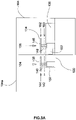
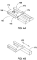
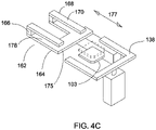
- FIG. 4 An exemplary first working area transport mechanism 162, which may be used to transport workpieces 108 between the first axial transport mechanism 120 and the working area 110, is illustrated.
- Figure 4A illustrates a perspective view of a first working area transport mechanism 162 which comprises a lower frame 164, of generally rectangular outline, having an opening 172 on one side 174 of the frame.
- the opening 172 extends substantially across the breadth of the frame 164 almost to opposite side 175 of the frame, so that the frame, taking into account the opening, is of a generally C-shape when viewed in plan.
- Projecting from an upper surface of the frame 164 is at least one vertical support member 166.
- two vertical support members 166 are provided, one on either side of the opening 172.
- One or more horizontal support members 168 extend from an upper part of the or each vertical sup port member 166, extending horizontally and generally parallel to the upper surface of the lower frame 164.
- the horizontal support member(s) 168 comprise one or more flat surface 170 on which a workpiece 108 may rest or be disposed.
- Figure 4B provides another perspective view of the first working area transport mechanism 162 including a driver mechanism 176 for providing the necessary displacement in directions 177.
- direction 177 is a lateral or generally lateral direction, lateral relative to axes 124, 128 of Figure 2 .
- a displaced first working area transport mechanism 162 is illustrated in dashed lines in Figure 4A .
- one or more horizontal support members 168 extend horizontally from the or each vertical support member 166 generally parallel to an upper surface of frame 164. As shown in Figure 4C , the spacing between the horizontal support members 168 and the upper surface of the support frame 164 defines a space (or volume) 178, and this facilitates transference of workpieces 108 between the first axial transport mechanism 120 and the first working area transport mechanism 162.
- first and second displacement mechanisms 132, 134 each respectively comprise displacement platforms 138, 146.
- first working area transport mechanism 120 is positioned generally in or adjacent to axis 124.
- First axial transport mechanism 120 is displaced downstream, as described above, so that platform 138 moves downstream in direction 126 along axis 124 and with platform 138 in the raised, distal position 144.
- the platform 136 and the workpiece 108 disposed thereon are situated adjacent to working area transport mechanism 162 which, by now, has been displaced to the position indicated by the dashed lines in Figure 4A (although it will be appreciated that it is not essential that the coordination of movement of the components is as described in this sequence).
- the platform 138 is positioned adjacent (co-located with) frame 164.
- First actuator mechanism 140 is operated to move platform 138 from the distal position 144 towards proximal position 142.
- the workpiece 108 is positioned on platform 138 so that a part of workpiece 108 overhangs an edge of platform 138 near the or each horizontal support member 168.
- the surface area of platform 138 is less (for example, significantly less) than the surface area of underside 114 of workpiece 108.
- the horizontal support members 168 may also extend significantly beyond the side 175 of frame 164. Therefore, as platform 138 moves from distal position 144 to proximal position 142 (the platform is lowered in this example) the underside 114 of workpiece 108 comes to rest on the upper surface(s) 170 of horizontal support members 168. Platform 138 - without workpiece 108 - continues to be lowered towards proximal position 142.
- Platform 138 is disposed generally adjacent the space/volume 178 between the horizontal support members 168 and frame 164.
- Transport drive mechanism 137 may thereafter operate to move platform 138 back upstream towards position 154 (while platform 138 is held stationery in the vertical plane in the proximal position 142) through volume 178 without clashing with working area transport mechanism 162, specifically frame 164 or the horizontal support members 168.
- the drive mechanism 176 operates to move frame 164 and the workpiece 108 disposed thereon along axis 177 towards working area 110.
- the first and second displacement mechanisms 132, 134 may additionally or alternatively be configured to transport workpieces to/from a holding area, such as a support frame or jig 103 thereat, in a similar manner.
- the transfer to/from the holding area support frame 103 can take place while the displacement platforms 138, 146 are at their respective proximal and distal positions, or during transitions between these positions.
- Holding area support frame 103 is movable between first and second positions indicated by the frame being shown in solid and in dashed lines in Figure 4C .
- modular workstation transport apparatus 100 also comprises a second working area transport mechanism for transporting the workpiece between the working area 110 and the second axial transport mechanism 122.
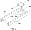
- An exemplary second working area transport mechanism 183 is illustrated in Figure 5 .
- First and second conveyors 180, 182 comprise, in this example, narrow conveyor belts arranged to transport workpieces 108 along axis 128.
- Conveyors 180, 182 are arranged to travel at least in upstream direction 130 of axis 128 (refer again to Figure 2 ), but may also be able to convey in a direction opposite direction 130, should that be desired.
- second axial transport mechanism 122 is shown disposed generally below working area 110. Therefore, in this example, second working area transport mechanism works generally in a vertical orientation for moving workpieces 108 between working area 110 and the second axial transport mechanism 122. As a minimum, the second working area transport mechanism may be arranged to transport workpieces from working area 110 to the second axial transport mechanism 122.
- Second working area transport mechanism comprises a displacement platform 184 and a third actuator mechanism 186.
- the third actuator mechanism 186 is configured to move third displacement platform 184 between third distal position 188 for third displacement platform 184 and third proximal position 190 for third displacement platform 184.
- the third proximal position 190 is a position closer to a support structure (not shown) for actuator mechanism 186 than the third distal position 188.
- the second working area transport mechanism 183 is, in this example, arranged for the transfer of workpieces 108 to/from second axial transport mechanism 122 (comprising first and second conveyor 180, 182) as the third actuator mechanism 186 moves third displacement platform 184 between third distal position 188 and third proximal position 190.
- third displacement platform 184 may be sized so that its cross-sectional area is less (for example significantly less) than the area of workpiece 108. Also, platform 184 may be sized such that it is able to fit in opening 172 of the frame 164 illustrated in Figure 4A . Moreover, as also seen in Figure 4A width of third displacement platform 184 is less than the distance between the gap between first and second conveyors 180 182. Thus, and recalling from Figure 2 that the second axial transport mechanism 122 may be disposed below working area 110, third displacement platform 184 may be positioned under working area 110, extending through opening 172 and pushing up a short distance to lift workpiece 108 off upper surface(s) 170 of the one or more horizontal support members 168.
- Drive mechanism 176 for the first working area transport mechanism 162 is operated to withdraw the frame along direction 177 away from third displacement platform 184, until clear from the footprint of the workpiece 108. Once clearance is achieved, the third displacement platform 184, with workpiece 180 thereon, may be lowered from third distal position 188 towards third proximal position 190. Operation of actuator mechanism 186 downwards continues, until third displacement platform 184 is brought below the level of the conveyors 180, 182. Workpiece 108 may then be disposed on conveyors 180, 182 for transportation along upstream axis 128 in direction 130.
- Second axial transport mechanism 120 be provided with a stopper (not shown) at or near the end of one conveyor module to stop the workpiece moving to the next modular transport workstation if the second axial transport mechanism of the upstream modular transport workstation is in operation.
- Figure 5 illustrates a modular workstation transport apparatus 100 further comprising a third displacement mechanism comprising a third displacement platform 184 and a third actuator mechanism 186 for moving the third displacement platform 184 between a third proximal position 190 and the third distal position 188 for transporting the workpiece 108 between the working area 110 and the second axial transport mechanism 124
- the system may be easily re-configured, where workstations can be added for scaling up the capacity. This can be done by simply adding one or more workstations at the end of the series of modular workstations, or inserting a new workstation in between two existing workstations. And of course, the reverse installation operation(s) can be conducted when scaling down capacity. Moreover, it is possible for a workstation to switch easily over to a different operating mode.
- one master unit operating on PLC control for the first axial transport mechanism controls up to 12 slave modules in one line with one master module and two slave modules. So in this exemplary arrangement for a total of 12 modules, there may be provided four master modules and 8 slave modules.
- At least four modes of operation are contemplated.
- a first of these is stand-alone mode illustrated in Figure 6A , where a workpiece is received at a transport mechanism, and conveyed to the working area as described above, then transported back upstream as also described above.
- a workpiece may be brought into a first modular workstation transport apparatus, again as described above with reference to Figure 3 .
- the first workstation is performing its manufacturing process
- the first axial transport mechanism conveys a second workpiece to the second workstation for manufacturing thereat and, also, a third workpiece to the third workstation for manufacturing thereat.
- a workpiece is brought into the working area of the first workstation. Thereafter, the workpiece is returned to the first axial transport mechanism for transportation to the second workstation, for the manufacturing operation to be carried out at that station. After having been operated on at the working area of the second workstation, the workpiece is conveyed back to the first axial transport mechanism for transportation to the third workstation. After the process is completed at the third workstation, the workpiece is transported to the second axial transport mechanism for returning back upstream.
- FIG. 6D Two combined or hybrid individual plus progressive modes of operation are also contemplated, as illustrated in Figures 6D and 6E .
- this is a progressive - progressive - individual - individual sequence of operation.
- the workpiece is returned back to the first axial transport mechanism for transportation to the second workstation, for manufacturing operations to be conducted thereat.
- the workstation is transported to the third workstation or the fourth workstation using the first axial transport mechanism.
- Each of the third and fourth workstations operate in the individual mode of operation so that when workpieces have been operated on at the stations, the workpieces are conveyed back to the second axial transport mechanism by the respective second working area transport mechanisms of the third and fourth workstations.
- FIG. 6E An individual - progressive - progressive - individual mode of operation is illustrated in Figure 6E .
- the first axial transport mechanism can continue to supply a workpiece to the second workstation.
- that workpiece is conveyed to the second axial transport mechanism for transporting back upstream.
- the workpiece is transported downstream using the first axial transport mechanism, to the third workstation for operation thereat and then onto the fourth workstation, also for operation thereat.
- the fourth workstation has completed its process, the workpiece is conveyed back to the second axial transport mechanism for transportation back upstream.
- a major contributing factor to the flexibility provided is that there are two exits from the working area 110 - a first one back to the first axial transport mechanism for further transfer downstream, and the second one on to the second axial transport mechanism 122 for transfer back upstream - the workpiece 108 can be transferred back upstream at any one of the modular workstation transport apparatus 100 in the series.
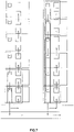
- Figure 7 is a layout diagram illustrating series of modular workstation transport apparatus installed for operation with workstations in a "horizontal" layout, with workpieces being supplied in from an infeed conveyor, down through a first series of workstations/transport apparatus in progressive mode, then backup to the infeed conveyor, before the workpieces are then transported down to another series of workstations/transport apparatus, also for operation in progressive mode thereat.
- Figure 8 is a layout diagram illustrating series of modular workstation transport apparatus installed for operation with workstations in a "vertical" layout, with workpieces being supplied in from an infeed conveyor, down through a first series of workstations/transport apparatus in progressive mode, then backup to the infeed conveyor, before the workpieces are then transported down to second, third and fourth series of workstations/transport apparatus, also for operation in progressive mode thereat.
- Figure 9 illustrates the flexibility in arranging the dock in position for the workstation with the modular workstation transport apparatus.
- the dock in position for the workstation is shown on the left-hand side, and the modular workstation transport apparatus has two "pallet positions", which provide two positions which may be used as working area areas 110.
- the dock in position for the workstation is shown in the centre, and the modular workstation transport apparatus has three pallet positions, providing three positions which may be used as working area areas 110.
- the dock in position for the workstation is shown at the right hand side, and modular workstation transport apparatus also has two pallet positions.
Landscapes
- Engineering & Computer Science (AREA)
- Manufacturing & Machinery (AREA)
- Physics & Mathematics (AREA)
- Condensed Matter Physics & Semiconductors (AREA)
- General Physics & Mathematics (AREA)
- Computer Hardware Design (AREA)
- Microelectronics & Electronic Packaging (AREA)
- Power Engineering (AREA)
- Mechanical Engineering (AREA)
- Automation & Control Theory (AREA)
- Automatic Assembly (AREA)
- Multi-Process Working Machines And Systems (AREA)
- Feeding Of Workpieces (AREA)
Claims (8)
- Modulare Arbeitsplatztransportvorrichtung, die als eine modulare Arbeitsplatztransportvorrichtung in einer Reihe von modularen Arbeitsplatztransportvorrichtungen betrieben werden kann, wobei die modulare Arbeitsplatztransportvorrichtung Folgendes umfasst:einen ersten axialen Transportmechanismus (120) zum Transportieren eines Werkstücks (108) entlang einer ersten axialen Richtung (126);einen zweiten axialen Transportmechanismus (122) zum Transportieren des Werkstücks (108) entlang einer zweiten axialen Richtung (130), wobei die zweite axiale Richtung der ersten axialen Richtung entgegengesetzt ist;einen Arbeitsbereich (110), der zum Durchführen eines Herstellungsprozesses an dem Werkstück konfiguriert ist;einen ersten Arbeitsbereichstransportmechanismus (162), der betrieben werden kann, um das Werkstück vom ersten axialen Transportmechanismus (120) zum Arbeitsbereich (110) zu transportieren;einen zweiten Arbeitsbereichstransportmechanismus (183), der zum Transportieren des Werkstücks vom Arbeitsbereich (110) zum zweiten axialen Transportmechanismus (122) konfiguriert ist;wobei die Vorrichtung so konfiguriert ist, dass sie einen ersten und einen zweiten Ausgang bereitstellt, die den Transport des Werkstücks aus dem Arbeitsbereich ermöglichen, der erste Ausgang zurück zum ersten axialen Transportmechanismus (120) und der zweite Ausgang zum zweiten axialen Transportmechanismus (122), und:
wobei der erste Arbeitsbereichstransportmechanismus (162) ferner betrieben werden kann, um das Werkstück aus dem Arbeitsbereich zurück zum ersten axialen Transportmechanismus (120) zu transportieren. - Modulare Arbeitsplatztransportvorrichtung nach Anspruch 1, wobei mindestens einer der Arbeitsbereichstransportmechanismen zum Bewegen von Werkstücken zwischen dem Arbeitsbereich und einem jeweiligen axialen Transportmechanismus ausgelegt ist, wobei der Arbeitsbereich vertikal in Bezug auf den genannten axialen Transportmechanismus angeordnet ist.
- Modulare Arbeitsplatztransportvorrichtung nach Anspruch 1 oder 2, wobei die modulare Arbeitsplatztransportvorrichtung eine strukturelle Umhüllung umfasst und der erste axiale Transportmechanismus zum Transportieren des Werkstücks von einer ersten Position außerhalb der strukturellen Umhüllung zu einer zweiten Position innerhalb der strukturellen Umhüllung ausgelegt ist.
- Modulare Arbeitsplatztransportvorrichtung nach Anspruch 1, 2 oder 3, wobei der erste axiale Transportmechanismus Folgendes umfasst:einen ersten Verschiebungsmechanismus, der Folgendes umfasst:eine erste Verschiebungsplattform; undeinen ersten Stellmechanismus zum Bewegen der ersten Verschiebungsplattform zwischen einer ersten proximalen Position und einer ersten distalen Position;einen zweiten Verschiebungsmechanismus, der Folgendes umfasst:eine zweite Verschiebungsplattform; undeinen zweiten Stellmechanismus zum Bewegen der zweiten Verschiebungsplattform zwischen einer zweiten proximalen Position und einer zweiten distalen Position; undeinen Transportantriebsmechanismus zum Antreiben des ersten Verschiebungsmechanismus und des zweiten Verschiebungsmechanismus axial entlang einer Achse des ersten axialen Transportmechanismus zwischen jeweiligen stromaufwärts und stromabwärts gelegenen Positionen.
- Modulare Arbeitsplatztransportvorrichtung nach Anspruch 4, so ausgelegt, dass die stromabwärts gelegene Position der ersten Verschiebungsplattform mit der stromaufwärts gelegenen Position der zweiten Verschiebungsplattform kolokalisiert wird.
- Modulare Arbeitsplatztransportvorrichtung nach Anspruch 4, wobei der zweite axiale Transportmechanismus ferner einen dritten Verschiebungsmechanismus umfasst, der Folgendes umfasst:eine dritte Verschiebungsplattform; undeinen dritten Stellmechanismus zum Bewegen der dritten Verschiebungsplattform zwischen einer dritten proximalen Position und einer dritten distalen Position, um das Werkstück zwischen dem Arbeitsbereich (110) und dem zweiten axialen Transportmechanismus zu transportieren.
- Reihe von modularen Arbeitsplatztransportvorrichtungen, die mehrere modulare Arbeitsplatztransportvorrichtungen nach einem vorherigen Anspruch umfasst.
- Verfahren zum Transportieren eines Werkstücks mit Hilfe einer modularen Arbeitsplatztransportvorrichtung nach einem der Ansprüche 1 bis 6.
Applications Claiming Priority (1)
| Application Number | Priority Date | Filing Date | Title |
|---|---|---|---|
| PCT/SG2015/050051 WO2016159871A1 (en) | 2015-03-27 | 2015-03-27 | Modular workstation transport apparatus and method of operation |
Publications (3)
| Publication Number | Publication Date |
|---|---|
| EP3274277A1 EP3274277A1 (de) | 2018-01-31 |
| EP3274277A4 EP3274277A4 (de) | 2018-11-14 |
| EP3274277B1 true EP3274277B1 (de) | 2022-05-25 |
Family
ID=57007361
Family Applications (1)
| Application Number | Title | Priority Date | Filing Date |
|---|---|---|---|
| EP15887928.8A Active EP3274277B1 (de) | 2015-03-27 | 2015-03-27 | Vorrichtung zum transport eines modularen arbeitsplatzes und verfahren zum betrieb |
Country Status (6)
| Country | Link |
|---|---|
| US (1) | US10647519B2 (de) |
| EP (1) | EP3274277B1 (de) |
| CN (1) | CN107428472B (de) |
| MY (1) | MY191978A (de) |
| SG (1) | SG11201707498XA (de) |
| WO (1) | WO2016159871A1 (de) |
Family Cites Families (20)
| Publication number | Priority date | Publication date | Assignee | Title |
|---|---|---|---|---|
| NL297192A (de) * | 1962-07-20 | |||
| US3966058A (en) * | 1975-06-30 | 1976-06-29 | C. M. Systems, Incorporated | Crankshaft transfer mechanism |
| AT398923B (de) * | 1989-04-04 | 1995-02-27 | Sticht Walter | Fertigungsanlage mit parallel- und nebenförderwegen |
| US5391047A (en) * | 1989-10-03 | 1995-02-21 | Globe Products Inc. | Apparatus for loading and unloading workpieces |
| JPH04261763A (ja) * | 1991-02-15 | 1992-09-17 | Sony Corp | 組立・加工装置 |
| JP2533984B2 (ja) * | 1991-05-29 | 1996-09-11 | 住友電気工業株式会社 | 加熱製品の多品種混流生産方法 |
| DE19504457A1 (de) * | 1995-02-10 | 1996-08-14 | Bosch Gmbh Robert | Modulare Fließfertigungsanlage |
| US6280134B1 (en) * | 1997-06-17 | 2001-08-28 | Applied Materials, Inc. | Apparatus and method for automated cassette handling |
| DE69813993D1 (de) * | 1997-10-29 | 2003-06-05 | Axis Spa | Vorrichtung und Verfahren zur Herstellung von Armaturen |
| JP2001162465A (ja) * | 1999-09-27 | 2001-06-19 | Denso Corp | 組立加工装置 |
| DE10102413C1 (de) * | 2001-01-16 | 2002-01-17 | Felsomat Gmbh & Co Kg | Automationszelle zur Handhabung von Werkstücken |
| JP4387727B2 (ja) * | 2003-08-14 | 2009-12-24 | 富士通株式会社 | 部品実装組立セル |
| CN1270948C (zh) * | 2004-03-08 | 2006-08-23 | 友达光电股份有限公司 | 基板输送装置及方法 |
| JP2005340499A (ja) * | 2004-05-27 | 2005-12-08 | Shimadzu Corp | 基板移載装置およびそれを備える基板処理装置 |
| US7296673B2 (en) * | 2005-06-10 | 2007-11-20 | Applied Materials, Inc. | Substrate conveyor system |
| JP4992668B2 (ja) * | 2007-10-31 | 2012-08-08 | 旭硝子株式会社 | 容器交換装置および容器交換方法 |
| KR20110080843A (ko) * | 2010-01-07 | 2011-07-13 | 세메스 주식회사 | 기판 이송 장치 |
| US20110245957A1 (en) * | 2010-04-06 | 2011-10-06 | Applied Materials, Inc. | Advanced platform for processing crystalline silicon solar cells |
| CN104122844B (zh) * | 2013-04-23 | 2017-05-03 | 纬创资通(昆山)有限公司 | 加工系统及加工方法 |
| US9789572B1 (en) * | 2014-01-09 | 2017-10-17 | Flextronics Ap, Llc | Universal automation line |
-
2015
- 2015-03-27 EP EP15887928.8A patent/EP3274277B1/de active Active
- 2015-03-27 SG SG11201707498XA patent/SG11201707498XA/en unknown
- 2015-03-27 WO PCT/SG2015/050051 patent/WO2016159871A1/en not_active Ceased
- 2015-03-27 CN CN201580078381.8A patent/CN107428472B/zh active Active
- 2015-03-27 US US15/561,006 patent/US10647519B2/en active Active
- 2015-03-27 MY MYPI2017703407A patent/MY191978A/en unknown
Also Published As
| Publication number | Publication date |
|---|---|
| EP3274277A1 (de) | 2018-01-31 |
| MY191978A (en) | 2022-07-21 |
| CN107428472B (zh) | 2020-06-02 |
| US20180050873A1 (en) | 2018-02-22 |
| WO2016159871A1 (en) | 2016-10-06 |
| EP3274277A4 (de) | 2018-11-14 |
| US10647519B2 (en) | 2020-05-12 |
| CN107428472A (zh) | 2017-12-01 |
| SG11201707498XA (en) | 2017-10-30 |
Similar Documents
| Publication | Publication Date | Title |
|---|---|---|
| CN108290259B (zh) | 制造设备和制造方法 | |
| CN109478579B (zh) | 用于在光伏电池上印刷的方法和自动生产设备 | |
| KR100290152B1 (ko) | 제품생산시스템 | |
| CN112041112B (zh) | 汽车白车身组件的组焊或拼接生产线 | |
| JP2001162465A (ja) | 組立加工装置 | |
| US8307972B2 (en) | Feed and removal system for machine tools | |
| US20230249297A1 (en) | Production station for workpieces, in particular vehicle body parts, and production system | |
| CN115241781B (zh) | 一种控制柜或电气柜背板装配生产线及其装配工艺 | |
| EP3274277B1 (de) | Vorrichtung zum transport eines modularen arbeitsplatzes und verfahren zum betrieb | |
| JP2016203354A (ja) | 生産システムおよび生産方法 | |
| CN111278614A (zh) | 定位和夹持系统及方法 | |
| CN115106670B (zh) | 一种货叉架机器人自动装焊系统以及焊接方法 | |
| CN217942380U (zh) | 一种货叉架机器人自动装焊系统 | |
| CN118107998A (zh) | 中转装置及pcb板输送系统 | |
| JP4334291B2 (ja) | ワーク授受装置及び加工システム | |
| CN210260043U (zh) | Pcb板输送系统 | |
| KR102681748B1 (ko) | 모바일 매니퓰레이터 | |
| CN210781951U (zh) | 一列式自动贴装设备和系统 | |
| CN214291871U (zh) | 箱式输送分拣设备模块与流水线结合式装配线 | |
| CN111376110A (zh) | 模块化的加工设备及其加工机台 | |
| JPH0857725A (ja) | 生産ラインにおけるライン構造 | |
| CN209273085U (zh) | 模块化的加工设备及其加工机台 | |
| CN220702274U (zh) | 传送装置及加工设备 | |
| CN119284408B (zh) | 铜排加工系统及加工方法 | |
| CN223175019U (zh) | 一种铁架装配流水线 |
Legal Events
| Date | Code | Title | Description |
|---|---|---|---|
| STAA | Information on the status of an ep patent application or granted ep patent |
Free format text: STATUS: THE INTERNATIONAL PUBLICATION HAS BEEN MADE |
|
| PUAI | Public reference made under article 153(3) epc to a published international application that has entered the european phase |
Free format text: ORIGINAL CODE: 0009012 |
|
| STAA | Information on the status of an ep patent application or granted ep patent |
Free format text: STATUS: REQUEST FOR EXAMINATION WAS MADE |
|
| 17P | Request for examination filed |
Effective date: 20171017 |
|
| AK | Designated contracting states |
Kind code of ref document: A1 Designated state(s): AL AT BE BG CH CY CZ DE DK EE ES FI FR GB GR HR HU IE IS IT LI LT LU LV MC MK MT NL NO PL PT RO RS SE SI SK SM TR |
|
| AX | Request for extension of the european patent |
Extension state: BA ME |
|
| DAV | Request for validation of the european patent (deleted) | ||
| DAX | Request for extension of the european patent (deleted) | ||
| A4 | Supplementary search report drawn up and despatched |
Effective date: 20181016 |
|
| RIC1 | Information provided on ipc code assigned before grant |
Ipc: B65G 37/02 20060101ALI20181010BHEP Ipc: H01L 21/677 20060101ALI20181010BHEP Ipc: B65G 15/00 20060101AFI20181010BHEP Ipc: H01L 21/67 20060101ALI20181010BHEP |
|
| STAA | Information on the status of an ep patent application or granted ep patent |
Free format text: STATUS: EXAMINATION IS IN PROGRESS |
|
| 17Q | First examination report despatched |
Effective date: 20201210 |
|
| GRAP | Despatch of communication of intention to grant a patent |
Free format text: ORIGINAL CODE: EPIDOSNIGR1 |
|
| STAA | Information on the status of an ep patent application or granted ep patent |
Free format text: STATUS: GRANT OF PATENT IS INTENDED |
|
| INTG | Intention to grant announced |
Effective date: 20211216 |
|
| GRAS | Grant fee paid |
Free format text: ORIGINAL CODE: EPIDOSNIGR3 |
|
| GRAA | (expected) grant |
Free format text: ORIGINAL CODE: 0009210 |
|
| STAA | Information on the status of an ep patent application or granted ep patent |
Free format text: STATUS: THE PATENT HAS BEEN GRANTED |
|
| AK | Designated contracting states |
Kind code of ref document: B1 Designated state(s): AL AT BE BG CH CY CZ DE DK EE ES FI FR GB GR HR HU IE IS IT LI LT LU LV MC MK MT NL NO PL PT RO RS SE SI SK SM TR |
|
| REG | Reference to a national code |
Ref country code: GB Ref legal event code: FG4D |
|
| REG | Reference to a national code |
Ref country code: CH Ref legal event code: EP |
|
| REG | Reference to a national code |
Ref country code: DE Ref legal event code: R096 Ref document number: 602015079202 Country of ref document: DE |
|
| REG | Reference to a national code |
Ref country code: AT Ref legal event code: REF Ref document number: 1494182 Country of ref document: AT Kind code of ref document: T Effective date: 20220615 |
|
| REG | Reference to a national code |
Ref country code: IE Ref legal event code: FG4D |
|
| REG | Reference to a national code |
Ref country code: LT Ref legal event code: MG9D |
|
| REG | Reference to a national code |
Ref country code: NL Ref legal event code: MP Effective date: 20220525 |
|
| REG | Reference to a national code |
Ref country code: AT Ref legal event code: MK05 Ref document number: 1494182 Country of ref document: AT Kind code of ref document: T Effective date: 20220525 |
|
| PG25 | Lapsed in a contracting state [announced via postgrant information from national office to epo] |
Ref country code: SE Free format text: LAPSE BECAUSE OF FAILURE TO SUBMIT A TRANSLATION OF THE DESCRIPTION OR TO PAY THE FEE WITHIN THE PRESCRIBED TIME-LIMIT Effective date: 20220525 Ref country code: PT Free format text: LAPSE BECAUSE OF FAILURE TO SUBMIT A TRANSLATION OF THE DESCRIPTION OR TO PAY THE FEE WITHIN THE PRESCRIBED TIME-LIMIT Effective date: 20220926 Ref country code: NO Free format text: LAPSE BECAUSE OF FAILURE TO SUBMIT A TRANSLATION OF THE DESCRIPTION OR TO PAY THE FEE WITHIN THE PRESCRIBED TIME-LIMIT Effective date: 20220825 Ref country code: NL Free format text: LAPSE BECAUSE OF FAILURE TO SUBMIT A TRANSLATION OF THE DESCRIPTION OR TO PAY THE FEE WITHIN THE PRESCRIBED TIME-LIMIT Effective date: 20220525 Ref country code: LT Free format text: LAPSE BECAUSE OF FAILURE TO SUBMIT A TRANSLATION OF THE DESCRIPTION OR TO PAY THE FEE WITHIN THE PRESCRIBED TIME-LIMIT Effective date: 20220525 Ref country code: HR Free format text: LAPSE BECAUSE OF FAILURE TO SUBMIT A TRANSLATION OF THE DESCRIPTION OR TO PAY THE FEE WITHIN THE PRESCRIBED TIME-LIMIT Effective date: 20220525 Ref country code: GR Free format text: LAPSE BECAUSE OF FAILURE TO SUBMIT A TRANSLATION OF THE DESCRIPTION OR TO PAY THE FEE WITHIN THE PRESCRIBED TIME-LIMIT Effective date: 20220826 Ref country code: FI Free format text: LAPSE BECAUSE OF FAILURE TO SUBMIT A TRANSLATION OF THE DESCRIPTION OR TO PAY THE FEE WITHIN THE PRESCRIBED TIME-LIMIT Effective date: 20220525 Ref country code: ES Free format text: LAPSE BECAUSE OF FAILURE TO SUBMIT A TRANSLATION OF THE DESCRIPTION OR TO PAY THE FEE WITHIN THE PRESCRIBED TIME-LIMIT Effective date: 20220525 Ref country code: BG Free format text: LAPSE BECAUSE OF FAILURE TO SUBMIT A TRANSLATION OF THE DESCRIPTION OR TO PAY THE FEE WITHIN THE PRESCRIBED TIME-LIMIT Effective date: 20220825 Ref country code: AT Free format text: LAPSE BECAUSE OF FAILURE TO SUBMIT A TRANSLATION OF THE DESCRIPTION OR TO PAY THE FEE WITHIN THE PRESCRIBED TIME-LIMIT Effective date: 20220525 |
|
| PG25 | Lapsed in a contracting state [announced via postgrant information from national office to epo] |
Ref country code: RS Free format text: LAPSE BECAUSE OF FAILURE TO SUBMIT A TRANSLATION OF THE DESCRIPTION OR TO PAY THE FEE WITHIN THE PRESCRIBED TIME-LIMIT Effective date: 20220525 Ref country code: PL Free format text: LAPSE BECAUSE OF FAILURE TO SUBMIT A TRANSLATION OF THE DESCRIPTION OR TO PAY THE FEE WITHIN THE PRESCRIBED TIME-LIMIT Effective date: 20220525 Ref country code: LV Free format text: LAPSE BECAUSE OF FAILURE TO SUBMIT A TRANSLATION OF THE DESCRIPTION OR TO PAY THE FEE WITHIN THE PRESCRIBED TIME-LIMIT Effective date: 20220525 Ref country code: IS Free format text: LAPSE BECAUSE OF FAILURE TO SUBMIT A TRANSLATION OF THE DESCRIPTION OR TO PAY THE FEE WITHIN THE PRESCRIBED TIME-LIMIT Effective date: 20220925 |
|
| PG25 | Lapsed in a contracting state [announced via postgrant information from national office to epo] |
Ref country code: SM Free format text: LAPSE BECAUSE OF FAILURE TO SUBMIT A TRANSLATION OF THE DESCRIPTION OR TO PAY THE FEE WITHIN THE PRESCRIBED TIME-LIMIT Effective date: 20220525 Ref country code: SK Free format text: LAPSE BECAUSE OF FAILURE TO SUBMIT A TRANSLATION OF THE DESCRIPTION OR TO PAY THE FEE WITHIN THE PRESCRIBED TIME-LIMIT Effective date: 20220525 Ref country code: RO Free format text: LAPSE BECAUSE OF FAILURE TO SUBMIT A TRANSLATION OF THE DESCRIPTION OR TO PAY THE FEE WITHIN THE PRESCRIBED TIME-LIMIT Effective date: 20220525 Ref country code: EE Free format text: LAPSE BECAUSE OF FAILURE TO SUBMIT A TRANSLATION OF THE DESCRIPTION OR TO PAY THE FEE WITHIN THE PRESCRIBED TIME-LIMIT Effective date: 20220525 Ref country code: DK Free format text: LAPSE BECAUSE OF FAILURE TO SUBMIT A TRANSLATION OF THE DESCRIPTION OR TO PAY THE FEE WITHIN THE PRESCRIBED TIME-LIMIT Effective date: 20220525 Ref country code: CZ Free format text: LAPSE BECAUSE OF FAILURE TO SUBMIT A TRANSLATION OF THE DESCRIPTION OR TO PAY THE FEE WITHIN THE PRESCRIBED TIME-LIMIT Effective date: 20220525 |
|
| REG | Reference to a national code |
Ref country code: DE Ref legal event code: R097 Ref document number: 602015079202 Country of ref document: DE |
|
| PG25 | Lapsed in a contracting state [announced via postgrant information from national office to epo] |
Ref country code: AL Free format text: LAPSE BECAUSE OF FAILURE TO SUBMIT A TRANSLATION OF THE DESCRIPTION OR TO PAY THE FEE WITHIN THE PRESCRIBED TIME-LIMIT Effective date: 20220525 |
|
| PLBE | No opposition filed within time limit |
Free format text: ORIGINAL CODE: 0009261 |
|
| STAA | Information on the status of an ep patent application or granted ep patent |
Free format text: STATUS: NO OPPOSITION FILED WITHIN TIME LIMIT |
|
| 26N | No opposition filed |
Effective date: 20230228 |
|
| PG25 | Lapsed in a contracting state [announced via postgrant information from national office to epo] |
Ref country code: SI Free format text: LAPSE BECAUSE OF FAILURE TO SUBMIT A TRANSLATION OF THE DESCRIPTION OR TO PAY THE FEE WITHIN THE PRESCRIBED TIME-LIMIT Effective date: 20220525 |
|
| P01 | Opt-out of the competence of the unified patent court (upc) registered |
Effective date: 20230514 |
|
| PG25 | Lapsed in a contracting state [announced via postgrant information from national office to epo] |
Ref country code: MC Free format text: LAPSE BECAUSE OF FAILURE TO SUBMIT A TRANSLATION OF THE DESCRIPTION OR TO PAY THE FEE WITHIN THE PRESCRIBED TIME-LIMIT Effective date: 20220525 |
|
| REG | Reference to a national code |
Ref country code: BE Ref legal event code: MM Effective date: 20230331 |
|
| PG25 | Lapsed in a contracting state [announced via postgrant information from national office to epo] |
Ref country code: LU Free format text: LAPSE BECAUSE OF NON-PAYMENT OF DUE FEES Effective date: 20230327 |
|
| PG25 | Lapsed in a contracting state [announced via postgrant information from national office to epo] |
Ref country code: IT Free format text: LAPSE BECAUSE OF FAILURE TO SUBMIT A TRANSLATION OF THE DESCRIPTION OR TO PAY THE FEE WITHIN THE PRESCRIBED TIME-LIMIT Effective date: 20220525 Ref country code: FR Free format text: LAPSE BECAUSE OF NON-PAYMENT OF DUE FEES Effective date: 20230331 |
|
| PG25 | Lapsed in a contracting state [announced via postgrant information from national office to epo] |
Ref country code: BE Free format text: LAPSE BECAUSE OF NON-PAYMENT OF DUE FEES Effective date: 20230331 |
|
| PG25 | Lapsed in a contracting state [announced via postgrant information from national office to epo] |
Ref country code: BG Free format text: LAPSE BECAUSE OF FAILURE TO SUBMIT A TRANSLATION OF THE DESCRIPTION OR TO PAY THE FEE WITHIN THE PRESCRIBED TIME-LIMIT Effective date: 20220525 |
|
| PG25 | Lapsed in a contracting state [announced via postgrant information from national office to epo] |
Ref country code: BG Free format text: LAPSE BECAUSE OF FAILURE TO SUBMIT A TRANSLATION OF THE DESCRIPTION OR TO PAY THE FEE WITHIN THE PRESCRIBED TIME-LIMIT Effective date: 20220525 |
|
| PGFP | Annual fee paid to national office [announced via postgrant information from national office to epo] |
Ref country code: DE Payment date: 20250317 Year of fee payment: 11 |
|
| PGFP | Annual fee paid to national office [announced via postgrant information from national office to epo] |
Ref country code: IE Payment date: 20250310 Year of fee payment: 11 |
|
| PGFP | Annual fee paid to national office [announced via postgrant information from national office to epo] |
Ref country code: GB Payment date: 20250327 Year of fee payment: 11 |
|
| PGFP | Annual fee paid to national office [announced via postgrant information from national office to epo] |
Ref country code: CH Payment date: 20250401 Year of fee payment: 11 |
|
| PG25 | Lapsed in a contracting state [announced via postgrant information from national office to epo] |
Ref country code: CY Free format text: LAPSE BECAUSE OF FAILURE TO SUBMIT A TRANSLATION OF THE DESCRIPTION OR TO PAY THE FEE WITHIN THE PRESCRIBED TIME-LIMIT; INVALID AB INITIO Effective date: 20150327 |
|
| PG25 | Lapsed in a contracting state [announced via postgrant information from national office to epo] |
Ref country code: HU Free format text: LAPSE BECAUSE OF FAILURE TO SUBMIT A TRANSLATION OF THE DESCRIPTION OR TO PAY THE FEE WITHIN THE PRESCRIBED TIME-LIMIT; INVALID AB INITIO Effective date: 20150327 |
|
| PG25 | Lapsed in a contracting state [announced via postgrant information from national office to epo] |
Ref country code: TR Free format text: LAPSE BECAUSE OF FAILURE TO SUBMIT A TRANSLATION OF THE DESCRIPTION OR TO PAY THE FEE WITHIN THE PRESCRIBED TIME-LIMIT Effective date: 20220525 |