EP3273548A1 - Push-pull-verbinder und sicherungselement für einen push-pullverbinder - Google Patents
Push-pull-verbinder und sicherungselement für einen push-pullverbinder Download PDFInfo
- Publication number
- EP3273548A1 EP3273548A1 EP17001234.8A EP17001234A EP3273548A1 EP 3273548 A1 EP3273548 A1 EP 3273548A1 EP 17001234 A EP17001234 A EP 17001234A EP 3273548 A1 EP3273548 A1 EP 3273548A1
- Authority
- EP
- European Patent Office
- Prior art keywords
- spring
- securing
- push
- base
- cylindrical
- Prior art date
- Legal status (The legal status is an assumption and is not a legal conclusion. Google has not performed a legal analysis and makes no representation as to the accuracy of the status listed.)
- Granted
Links
Images



Classifications
-
- H—ELECTRICITY
- H01—ELECTRIC ELEMENTS
- H01R—ELECTRICALLY-CONDUCTIVE CONNECTIONS; STRUCTURAL ASSOCIATIONS OF A PLURALITY OF MUTUALLY-INSULATED ELECTRICAL CONNECTING ELEMENTS; COUPLING DEVICES; CURRENT COLLECTORS
- H01R13/00—Details of coupling devices of the kinds covered by groups H01R12/70 or H01R24/00 - H01R33/00
- H01R13/62—Means for facilitating engagement or disengagement of coupling parts or for holding them in engagement
- H01R13/627—Snap or like fastening
- H01R13/6271—Latching means integral with the housing
- H01R13/6273—Latching means integral with the housing comprising two latching arms
Definitions
- the invention relates to a push-pull connector, in particular a securing element for a push-pull connector for connecting the push-pull connector with a complementary socket.
- Previously known push-pull connectors include, among other things, a control element and a fuse element arranged in the control element.
- the fuse element has the task of securing a socket compatible with the push-pull connector to the push-pull connector such that the push-pull connector can not come loose from the socket.
- known fuse elements on safety lugs which engage in the socket. Thus, the push-pull connector can not be removed from the socket and / or disconnect.
- the plug socket and the push-pull connector are pulled apart in known push-pull connectors.
- the push-pull connector on a control element which causes by pulling an unlocking operation of the securing element, which cancels the engagement of the locking lugs in the socket.
- the cylindrical base may have a hollow cylindrical shape. That is, the cylindrical base may be tubular and extend from the initial position along the connecting direction.
- the direction in which the push-pull connector is insertable into the receptacle can be referred to as the connection direction. That is, the connection direction extends from the initial position in the direction of the socket and can as substantially orthogonal to one through the cylindrical base defined circular cross-sectional area are considered.
- the connection direction may be considered to be substantially parallel to the cylinder axis of the cylindrical base.
- the difference in outer diameter and inner diameter is twice the wall thickness of the cylindrical base.
- the securing region can also be formed substantially hollow cylindrical.
- the securing region can be arranged relative to the cylindrical base such that a straight line arranged on the cylinder axis of the securing region lies on a straight line arranged on the cylinder axis of the cylindrical base.
- the extended cylinder axis of the cylindrical securing portion may lie on the extended cylinder axis of the cylindrical base.
- the at least one guide wall may in particular be rigid.
- the at least one guide wall can be designed so that the at least one guide wall can not be changed by the action of force in position and position relative to the cylinder axis of the securing area, unless the force exceeds the limit of material failure.
- the at least one spring can be designed to be resilient in a radial direction pointing to the cylinder axis of the securing area.
- the position and position of the at least one spring with respect to the cylinder axis of the securing area can be changed by a force. That is, the spring may be moved toward the cylinder axis of the securing area by a force acting on an outer side of the at least one spring and directed toward the cylinder axis of the securing area.
- the nose By moving the at least one spring in the direction of the cylinder axis of the securing area, the nose can also move in the direction of the cylinder axis of the securing area.
- the at least one spring may be formed as an elongate spring body, wherein the elongated spring body arranged substantially parallel to the connecting direction can be.
- the nose may be configured to engage the complementary receptacle. That is, in a connected state between the female connector and the push-pull connector, the nose engages the female connector so as to hinder and / or prevent disconnection between the female connector and the push-pull connector.
- a corresponding recess may be provided in the complementary socket into which the wet can engage.
- the at least one spring is in the actuated state of the termination plane spaced or contacted.
- the state can be considered, in which the at least one spring in the direction of the cylinder axis of the securing area. is moved so that the nose does not engage in the socket.
- the push-pull connector can not secure the receptacle.
- one end of the at least one spring in the actuated state can be spaced from the termination plane, or the end of the spring contacts this termination plane. This means contacted that the end of the spring does not pierce the final level, but lies on the final level. In other words, in an actuated state, the spring may terminate before or at the termination plane.
- This design of the at least one spring can ensure that the at least one spring in an actuated state does not conflict with other components of the push-pull connector. In other words, movement of the spring toward the actuated state is not hindered by components located in the direction of movement.
- the at least one spring can have a flat shape exhibit.
- the at least one spring has a small thickness, wherein the thickness may correspond substantially to the wall thickness of the cylindrical base.
- the wall thickness of the at least one spring can vary in your course.
- the recesses which space the at least one spring from the at least one guide wall, may essentially be formed as slots in the cylinder jacket of the securing element, wherein the slots may be formed substantially parallel to the cylinder axis of the cylindrical securing area.
- the recesses may each have the same width or different widths.
- the width of the recesses that is to say the distance between the at least one guide wall and the at least one spring, can vary along the extension direction of the recess and / or the connecting direction.
- the recesses may be stepped, i. the recesses may have a first width in a first section and have a second width in a second section adjoining the first section.
- the first width may have a dimension of about 0.3 mm and the second width may have a dimension of about 0.6 mm.
- the first portion may extend from the cylindrical base along the connection direction, the second portion extending from the first portion along the connection direction.
- the first portion is disposed between the cylindrical base and the second portion.
- the first portion and the second portion may be reversed.
- the securing element can be arranged in an operating element of the push-pull connector.
- the securing element can be designed to be movable within the operating element relative to the operating element. That is, the securing element can be moved relative to the operating element along the cylinder axis of the securing element.
- the operating element can be designed as movable relative to the securing element. That is, the operating element may be relative to the securing element along the cylinder axis of the securing element and / or along the connecting direction to be moved.
- the at least one spring may have a central portion and an end portion, the central portion extending from the base toward the end position and / or end portion.
- the middle section connects the base and the end section.
- the central portion may be formed in an unactuated state, ie in a state without force acting on the spring element, substantially parallel to the cylinder axis of the securing area.
- the inner surface and / or inner side of the central portion may be formed in an unactuated state substantially parallel to the cylinder axis of the securing area.
- the inner surface of the end portion may be inclined relative to the connecting direction or relative to the cylinder axis of the securing area by the angle ⁇ .
- the angle ⁇ can determine the distance of the inner surface of the end portion to the cylinder axis of the security area.
- the distance between the inner surface of the securing region and the cylinder axis of the securing region can increase starting from the middle section along the connecting direction.
- An actuation of the spring can lead to a reduction of the angle ⁇ , wherein the angle ⁇ can also assume negative values.
- the end of the spring and / or the spring can be brought closer to the termination plane, wherein the end of the spring and / or the spring can be spaced from the termination plane or contacted.
- the end of the spring and / or the spring abut against the termination plane. That is, the end of the spring and / or the spring does not penetrate the termination plane in the contacted state.
- the nose can be arranged on an outer surface of the end portion and the nose can have a ramp. Further, the ramp may be tapered toward the center portion in a direction orthogonal to the connection direction.
- the outer surface of the end portion may be the surface of the end portion facing away from the cylinder axis of the securing portion.
- the nose becomes thicker in its course from the end position toward the starting position. In other words, the nose extends approximately in a radial direction from the cylinder axis of the securing area, more precisely radially outward.
- the ramp may be intended to contact a control element. By moving a suitable operating element, a force can be exerted on the ramp and thus on the spring so that the at least one spring is moved in the direction of the cylinder axis of the securing area.
- the nose may be stepped to the central portion at the end of a first section and have a gradation.
- the first subsection may be a section of the end section which is located at the end position.
- the gradation of the nose may be formed substantially orthogonal to the outer surface of the end portion.
- the stepped portion and / or the pitch of the tab may be configured to secure a complementary receptacle when the complementary receptacle is connected to the push-pull connector.
- the stepped portion can engage in an opening of the complementary socket.
- the securing area can be stepped in relation to the base. That is, the outer diameter of the cylindrical securing portion may be smaller than the outer radius diameter of the cylindrical base.
- the gradation between the base and the securing area can be determined by an appropriate connection between the cylindrical base and the cylindrical securing area can be achieved.
- the gradation between the base and securing areas can also be cylindrical or hollow cylindrical.
- the gradation can be made by a connecting element which connects the cylindrical base with the cylindrical securing area.
- the recesses may extend into the base.
- the length of the spring relative to the connecting direction can be increased, so that a greater spring travel is available. This can reduce the force required to operate the spring.
- the push-pull connector can be operated more sensitively and easily.
- the securing portion may comprise a second spring for connecting the complementary socket, wherein the second spring of the at least one spring may be arranged opposite.
- the second spring may be arranged opposite to the at least one spring with respect to the cylinder axis.
- the securing element can also have two guide walls, which are arranged opposite one another with respect to the cylinder axis of the securing area. Furthermore, the two guide walls can each be arranged between the two springs.
- the second spring may be structurally and functionally configured as the at least one spring.
- the securing element may also comprise three or four springs.
- the operating element may be designed to receive the securing element.
- the cylindrical connection region may be formed as a hollow cylinder.
- the cylindrical connection portion may have an inner radius which is adapted to receive the cylindrical securing portion of the securing element.
- the cylindrical grip portion may be formed as a hollow cylinder.
- the inner diameter of the cylindrical grip portion may be larger than the outer diameter of the cylindrical base of the securing member.
- the cylindrical grip portion may be adapted to receive the cylindrical base.
- the operating element may be designed such that the securing element can be moved within the operating element. In particular, the securing element can be moved within the operating element along the connecting direction and against the connecting direction.
- the at least one opening of the operating element can interact with the nose.
- the moving may cause a force transfer of the operating element to the nose, which causes an actuation, that is, the assumption of the actuated state, which causes at least one spring.
- a boundary of the opening of the operating element may be designed to be in contact with the nose.
- the opening may be formed, for example, quadrangular.
- one side of the square opening may be configured to contact the ramp of the nose.
- one side of the square opening can contact the ramp of the nose.
- a force is thus exerted on the at least one spring via the ramp in order to move the spring in the direction of the cylinder axis of the cylindrical securing region.
- the control element for each Spring or nose on a corresponding opening.
- the operating element may be rigid and / or non-deformable.
- FIG. 1 10 shows a perspective view of a push-pull connector 100 and a cable 200 which is arranged in the push-pull connector 100, as well as an operating element 20 of the push-pull connector 100.
- the Z-direction of the illustrated coordinate system represents the connection direction of the push-pull connector 100, ie the direction in which the push-pull connector is connected to a complementary socket.
- the connection direction points from the cable 200 to a plug end of the push-pull connector 100, with the plug end of the push-pull connector 100 corresponding to the complementary socket-facing end of the push-pull connector when the push-pull Connector is connected to the socket.
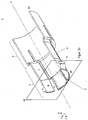
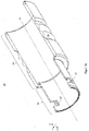
- FIGS. 2a and 2 B each show a longitudinal section through a securing element 1.
- the securing element 1 comprises a cylindrical base 3 which extends from an initial position AP toward an end position EP along the connecting direction.
- the initial position AP is arranged on a cable-side end of the securing element 1, and the end position EP on a plug-side end of the securing element 1.
- the connecting direction corresponds to the illustrated Z-direction of the illustrated coordinate system.
- the connecting direction is substantially parallel to the cylinder axis H of the cylindrical base 3.
- the cylindrical base 3 may be formed substantially hollow cylindrical. That is, the cylindrical base 3 has both an inner diameter and an outer diameter. The difference between the outer diameter and the inner diameter determines the wall thickness of the cylindrical base 3.
- FIGS. 2a and 2 B each show at least one guide wall 5, which, starting from the cylindrical base 3 along the Connecting direction or Z-direction extends. Further show FIGS. 2a and 2 B at least one spring 6 of the securing region 2, which extends from the base 3 along the connecting direction and / or Z-direction.
- the at least one guide wall 5 extends to the end position EP.
- a termination plane AE which is spanned orthogonal to the cylinder axis H and / or to the connection direction and / or to the Z direction.
- the end of the spring 6 and / or the spring 6 is spaced in an actuated state of this final plane AE or contacted them.
- the spring 6 ends before or at the termination plane AE.
- the at least one spring 6 is spaced from the at least one guide wall 5 by recesses 4.
- the recesses 4 are formed in the wall of the securing area 2 and penetrate the securing area 2 along its entire length in the connecting direction and / or in the Z direction, ie from the base 3 to the end position EP.
- the recesses 4 may extend into the base 3 in.
- the recesses 4 may extend up to 10%, preferably 20% and most preferably up to 50% into the base.
- the base 3 may have a length of approximately 14.85 mm, with the recesses 4 extending approximately 11.35 mm into the base.
- the springs 6 are lengthened.
- the springs 6 have a correspondingly longer spring travel, as a result of which the springs 6 can be actuated with less effort.
- the springs 6 are easier to operate and the required use of force can be better dosed and / or estimated.
- the securing element 1 comprises two substantially identical springs 6, which are arranged with respect to each other and / or with respect to the cylinder axis H symmetrical to each other.
- the securing element 1, a spring 6, or even three or more springs exhibit.
- FIGS. 2a and FIG. 2b show FIGS. 2a and FIG. 2b in that the cylindrical securing area 2 is stepped in a radial direction with respect to the cylindrical base 3.
- the cylindrical base 3 falls down towards the cylindrical securing region 2, that is to say the securing element 1 narrows along the connecting direction.
- the securing area 2 has a smaller inner diameter and / or outer diameter than the base 3.
- the spring 6 has a central portion 7 and an end portion 8.
- the central portion 7 extends from the cylindrical base 3 in the direction of the end position, wherein the central portion 7 connects the cylindrical base 3 with the end portion 8.
- a nose 9 is arranged on the outer side and / or outer surface of the end portion 8. The nose 9 may be configured to snap into an opening of a complementary receptacle and / or to secure the push-pull connector 100 in the mating receptacle.
- FIG. 2b shows that the end section 8 is inclined by an angle ⁇ relative to the cylinder axis H or the connecting direction or also the Z direction.
- the angle ⁇ decreases and the spacing of the end of the spring 6 from the terminating plane AE is reduced.
- the end portion 8 does not penetrate the termination plane AE in an actuated state.
- the end portion 8 ends in an actuated state of the spring 6 before or at the final plane AE.
- the nose 9, which is arranged on the outer side or the outer surface of the end portion 8, thickened starting from the end position EP against the connecting direction, ie opposite to the Z direction.
- the nose 9 forms a rising ramp in a first nose portion.
- This ramp is followed by a second nose portion having a substantially parallel surface with respect to the cylinder axis H.
- the nose 9 abruptly drops so that the sloping surface and the outer surface of the end portion 8 are substantially orthogonal to each other.
- the wall thicknesses of the spring 6 and the guide wall 5 can be designed differently.
- each of the wall thicknesses of the spring 6 and the guide wall 5 can vary in their course.
- the central portion 7 of the spring 6 have a different wall thickness than the end portion 8 of the spring.
- the wall thickness of the middle section 7 and of the end section 8 of the spring 6 can have a different wall thickness than the wall thickness of the cylindrical base 3 or the guide wall 5.
- FIGS. 3a and FIG. 3b show a preferred embodiment of the control element 20 of the present invention in a longitudinal section.
- the operating element 20 comprises a cylindrical grip region 21, which may have a substantially hollow cylindrical shape as shown. That is, the cylindrical grip portion 21 has an inner diameter and an outer diameter, wherein the difference of outer diameter and inner diameter defines the wall thickness of the cylindrical grip portion. Furthermore, the grip area 21 on the outside can have recesses 25, which increase the grip of the grip area 21. Thus, the handle portion 21 can be more easily grasped by a user and operated more comfortable.
- a cylindrical connection region 22 extends along the connection direction or the Z direction.
- the cylindrical connecting portion 22 is formed substantially hollow cylindrical and has an outer diameter and an inner diameter, wherein the difference of the outer diameter to the inner diameter defines the wall thickness of the cylindrical connecting portion 22. Further, the connection portion 22 is adapted to be inserted into a complementary female connector.
- connection region 22 has at least one opening 23.
- the connection region 22 has two openings 23 and 24.
- the number of openings 23, 24 corresponds to the number of springs 6 of the securing element 1. That is, when the securing element 1 has three or more springs, also has the cylindrical connection portion 22 via correspondingly many openings 23, 24.
- the control element 20 is substantially rigid and / or non-deformable.
- FIG. 3a and FIG. 3b show that the cylindrical connection region 22 can be stepped relative to the cylindrical grip region 21.
- the gradation between the cylindrical connecting portion 22 and the cylindrical grip portion 21 can be made by a connecting member connecting the cylindrical grip portion 21 to the cylindrical connecting portion 22.
- a guide lug 26 may be provided on the outer surface of the cylindrical connection region 22, which facilitates the connection of a complementary socket with the push-pull connector 100 or the connection region 22.
- a corresponding recess may be provided in a complementary socket.
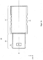
- FIG. 4a shows the fuse element 1 according to the invention and the control element 20 according to the invention in the assembled state.
- the cylindrical securing region 2 of the securing element 1 is arranged within the cylindrical connecting region 22 of the operating element 20 and the cylindrical base 3 of the securing element 1 is arranged within the cylindrical grip region 21 of the operating element 20.
- the securing element 1 is designed to be movable within the operating element 20. That is, the operating element 20 can be moved along and / or against the connecting direction (along and / or counter to the Z direction) relative to the securing element 1, so that the securing element 1 is displaced with respect to the operating element 20.
- the end of the spring 6 is spaced from the termination plane.
- the spring 6 that is, the movement of the spring 6 in the direction of the cylinder center or cylinder axis H, the spacing of the spring 6 is reduced to the final plane AE.
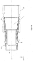
- FIG. 4b shows a longitudinal section through a partially assembled push-pull connector 100.
- the fuse element 1 is disposed within the operating element 20.
- FIG. 4b another component 30 of the push-pull connector 100, which is arranged within the securing element 1.
- the component 30 has on the outside a recess 31, which is arranged opposite to the spring 6. Characterized in that in an actuated state, the spring 6 and / or the end portion 8 terminate before or at the final plane AE, the spring 6 and / or the end portion 8 when pressing the spring in the recess 31 of the device 30 engage.
Landscapes
- Details Of Connecting Devices For Male And Female Coupling (AREA)
- Fuses (AREA)
Abstract
Description
- Die Erfindung betrifft einen Push-Pull-Verbinder, insbesondere ein Sicherungselement für einen Push-Pull-Verbinder zum Verbinden des Push-Pull-Verbinders mit einer komplementären Steckerbuchse.
- Bisher bekannte Push-Pull-Verbinder umfassen unter anderem ein Bedienelement und ein in dem Bedienelement angeordnetes Sicherungselement. Das Sicherungselement hat die Aufgabe, eine mit dem Push-Pull-Verbinder kompatible Steckerbuchse an dem Push-Pull-Verbinder derart zu sichern, dass sich der Push-Pull-Verbinder nicht von der Steckerbuchse lösen kann. Dazu weisen bekannte Sicherungselemente Sicherungsnasen auf, die in die Steckerbuchse eingreifen. Somit lässt sich der Push-Pull-Verbinder nicht von der Steckerbuchse abziehen und/oder trennen.
- Zum Trennen des Push-Pull-Verbinders von der Steckerbuchse ist es notwendig, das Eingreifen der Sicherungsnasen in die Steckerbuchse aufzuheben. Dazu werden bei bekannten Push-Pull-Verbindern die Steckerbuchse und der Push-Pull-Verbinder auseinander gezogen. In der Regel weist der Push-Pull-Verbinder ein Bedienelement auf, welches durch Ziehen einen Entriegelungsvorgang des Sicherungselements bewirkt, welcher das Eingreifen der Sicherungsnasen in die Steckerbuchse aufhebt.
- Bisher bekannte Push-Pull-Verbinder benötigen beim Trennen des Push-Pull-Verbinders von der Steckerbuchse jedoch einen großen Kraftaufwand. Des Weiteren erfolgt das Lösen der Steckerbuchse abrupt. Das heißt, die Steckerbuchse und der Push-Pull-Verbinder werden mit ansteigender Zugkraft auseinander gezogen, ohne ein Trennung zu verursachen. Nach dem Erreichen einer bestimmten Zugkraft erfolgt das Lösen der Steckerbuchse von dem Push-Pull-Verbinder dann unmittelbar bzw. plötzlich und unerwartet. Des Weiteren lässt sich die für das Lösen der Verbindung zwischen Push-Pull-Verbinder und Steckerbuchse benötigte Zugkraft nur schwer dosieren und/oder abschätzen.
- Es ist daher Aufgabe der Erfindung einen Push-Pull-Verbinder und eine Steckerbuchse in einfacher und komfortabler Weise zu trennen und/oder zu lösen.
- Diese Aufgabe wird durch ein Sicherungselement für einen Push-Pull-Verbinder mit den Merkmalen des Anspruchs 1 sowie ein Bedienelement für einen Push-Pull-Verbinder mit den Merkmalen des Anspruchs 8 gelöst.
- Ein Aspekt der Erfindung betrifft ein Sicherungselement für einen Push-Pull-Verbinder zum Verbinden des Push-Pull-Verbinders mit einer komplementären Steckerbuchse, umfassend:
- eine zylindrische Basis, welche sich ausgehend von einer Anfangsposition entlang einer Verbindungsrichtung erstreckt;
- einen zylindrischen Sicherungsbereich, wobei sich der Sicherungsbereich ausgehend von der Basis entlang der Verbindungsrichtung bis zu einer Endposition erstreckt, wobei der Sicherungsbereich weiter umfasst:
- zumindest eine Führungswand, welche sich ausgehend von der Basis entlang der Verbindungsrichtung bis zu der Endposition erstreckt; und
- zumindest eine Feder, welche sich ausgehend von der Basis entlang der Verbindungsrichtung erstreckt, wobei die zumindest eine Feder eine Nase aufweist und von der zumindest einen Führungswand durch Aussparungen beabstandet ist und wobei die zumindest eine Feder in einem betätigten Zustand von einer Abschlussebene, welche orthogonal zur Verbindungsrichtung an der Endposition aufgespannt ist, beabstandet ist oder diese Ebene kontaktiert.
- Die zylindrische Basis kann eine hohlzylindrische Form aufweisen. Das heißt, die zylindrische Basis kann röhrenförmig ausgestaltet sein und sich ausgehend von der Anfangsposition entlang der Verbindungsrichtung erstrecken. Für die vorliegende Offenbarung kann als Verbindungsrichtung die Richtung bezeichnet werden, in welche der Push-Pull-Verbinder in die Steckerbuchse einführbar ist. Das heißt, die Verbindungsrichtung erstreckt sich ausgehend von der Anfangsposition in Richtung Steckerbuchse und kann als im Wesentlichen orthogonal zu einer durch die zylindrische Basis definierte kreisförmige Querschnittsfläche angesehen werden. Somit kann die Verbindungsrichtung als im Wesentlichen parallel zur Zylinderachse der zylindrischen Basis angesehen werden.
- Für den Fall, dass die zylindrische Basis eine hohlzylindrische Form aufweist, bilden die Differenz aus Außendurchmesser und Innendurchmesser das Zweifache der Wandstärke der zylindrischen Basis.
- Der Sicherungsbereich kann im Wesentlichen ebenfalls hohlzylindrisch ausgebildet sein. Der Sicherungsbereich kann gegenüber der zylindrischen Basis so angeordnet sein, dass eine auf der Zylinderachse des Sicherungsbereichs angeordnete Gerade auf einer auf der Zylinderachse der zylindrischen Basis angeordneten Geraden liegt. Mit anderen Worten, die verlängerte Zylinderachse des zylindrischen Sicherungsbereichs kann auf der verlängerten Zylinderachse der zylindrischen Basis liegen.
- Die zumindest eine Führungswand kann insbesondere starr ausgebildet sein. Mit anderen Worten kann die zumindest eine Führungswand so ausgebildet sein, dass die zumindest eine Führungswand durch Krafteinwirkung in Position und Lage relative zur Zylinderachse des Sicherungsbereichs nicht veränderbar ist, außer die Krafteinwirkung überschreitet die Grenze zum Materialversagen.
- Die zumindest eine Feder kann in einer radialen zur Zylinderachse des Sicherungsbereichs weisenden Richtung federnd ausgestaltet sein. Die Position und Lage der zumindest einen Feder in Bezug auf die Zylinderachse des Sicherungsbereichs, kann durch eine Krafteinwirkung verändert werden. Das heißt, die Feder kann durch eine Kraft, welche auf eine Außenseite der zumindest einen Feder wirkt und welche in Richtung zur Zylinderachse des Sicherungsbereichs hin gerichtet ist, in Richtung zur Zylinderachse des Sicherungsbereichs hin bewegt werden. Durch das Bewegen der zumindest einen Feder in Richtung zur Zylinderachse des Sicherungsbereichs hin, kann sich die Nase ebenfalls in Richtung zur Zylinderachse des Sicherungsbereichs hin bewegen. Des Weiteren kann die zumindest eine Feder als länglicher Federkörper ausgebildet sein, wobei der längliche Federkörper im Wesentlichen parallel zur Verbindungsrichtung angeordnet sein kann.
- Die Nase kann dazu ausgebildet sein, in die komplementäre Steckerbuchse einzugreifen. Das heißt, in einem verbundenen Zustand zwischen Steckerbuchse und Push-Pull-Verbinder greift die Nase so in die Steckerbuchse ein, dass ein Lösen der Verbindung zwischen Steckerbuchse und Push-Pull-Verbinder behindert und/oder verhindert wird. Dazu kann in der komplementären Steckerbuchse eine entsprechende Aussparung vorgesehen sein, in welche die Nasse eingreifen kann. Beim Einwirken der oben genannten Kraft auf die Nase und/oder Feder, kann das Eingreifen der Nase in die Steckerbuchse aufgehoben werden, so dass die Steckerbuchse vom Push-Pull-Verbinder gelöst werden kann. Dieser Zustand der Feder wird in der vorliegenden Offenbarung als betätigter Zustand bezeichnet.
- Die zumindest eine Feder ist im betätigten Zustand von der Abschlussebene beabstandet oder kontaktiert diese. Als betätigten Zustand der zumindest einen Feder kann der Zustand angesehen werden, in dem die zumindest eine Feder in Richtung zur Zylinderachse des Sicherungsbereichs. hin bewegt ist, so dass die Nase nicht in die Steckerbuchse eingreift. Mit anderen Worten, in einem betätigten Zustand kann der Push-Pull-Verbinder die Steckerbuchse nicht sichern.
- Insbesondere kann ein Ende der zumindest einen Feder im betätigten Zustand von der Abschlussebene beabstandet sein oder das Ende der Feder kontaktiert diese Abschlussebene. Dabei bedeutet kontaktiert, dass das Ende der Feder die Abschlussebene nicht durchstößt, sondern auf der Abschlussebene liegt. Mit anderen Worten, in einem betätigten Zustand kann die Feder vor oder an der Abschlussebene enden.
- Durch diese Ausbildung der zumindest einen Feder kann gewährleistet werden, dass die zumindest eine Feder in einem betätigten Zustand nicht in Konflikt mit anderen Bauelementen des Push-Pull-Verbinders steht. Mit anderen Worten, ein Bewegen der Feder hin zu dem betätigten Zustand wird nicht durch in Bewegungsrichtung befindliche Bauelemente behindert.
- In Verbindungsrichtung betrachtet, kann die zumindest eine Feder eine flache Form aufweisen. Mit anderen Worten, die zumindest eine Feder weist eine geringe Dicke auf, wobei die Dicke im Wesentlichen der Wandstärke der zylindrischen Basis entsprechen kann. Die Wandstärke der zumindest einen Feder kann in Ihrem Verlauf variieren.
- Die Aussparungen, welche die zumindest eine Feder von der zumindest einen Führungswand beabstanden, können im Wesentlichen als Schlitze im Zylindermantel des Sicherungselements ausgebildet sein, wobei die Schlitze im Wesentlichen parallel zur Zylinderachse des zylindrischen Sicherungsbereichs ausgebildet sein können. Die Aussparungen können jeweils die gleiche Breite oder auch unterschiedliche Breiten aufweisen. Des Weiteren kann die Breite der Aussparungen, das heißt der Abstand zwischen der zumindest einen Führungswand und der zumindest einen Feder, entlang der Erstreckungsrichtung der Aussparung und/oder bzw. der Verbindungsrichtung variieren. Insbesondere können die Aussparungen abgestuft ausgebildet sein, d.h. die Aussparungen können in einem ersten Abschnitt eine erste Breite aufweisen und in einem sich an den ersten Abschnitt anschließenden zweiten Abschnitt eine zweite Breite aufweisen. Beispielhaft kann die erste Breite eine Abmessung von circa 0,3 mm aufweisen und die zweite Breite eine Abmessung von circa 0,6 mm aufweisen. Vorzugsweise kann der erste Abschnitt sich ausgehend von der zylindrischen Basis entlang der Verbindungsrichtung erstrecken, wobei der zweite Abschnitt sich ausgehend vom ersten Abschnitt entlang der Verbindungsrichtung erstreckt. Mit anderen Worten der erste Abschnitt ist zwischen der zylindrischen Basis und dem zweiten Abschnitt angeordnet. Alternativ können der erste Abschnitt und der zweite Abschnitt umgekehrt angeordnet sein.
- Des Weiteren kann das Sicherungselement in einem Bedienelement des Push-Pull-Verbinders angeordnet sein. Insbesondere kann das Sicherungselement innerhalb des Bedienelements relativ zu dem Bedienelement beweglich ausgebildet sein. Das heißt, das Sicherungselement kann relativ zu dem Bedienelement entlang der Zylinderachse des Sicherungselements bewegt werden. Ebenso kann das Bedienelement als beweglich relativ zu dem Sicherungselement ausgebildet sein. Das heißt, dass Bedienelement kann relativ zu dem Sicherungselement entlang der Zylinderachse des Sicherungselements und/oder entlang der Verbindungsrichtung bewegt werden.
- Vorzugsweise kann die zumindest eine Feder einen Mittelabschnitt und einen Endabschnitt aufweisen, wobei sich der Mittelabschnitt von der Basis in Richtung Endposition und/oder Endabschnitt erstreckt. Der Mittelabschnitt verbindet die Basis und den Endabschnitt. Bei einer Betrachtung des Längsschnitts durch das Sicherungselement parallel zur Verbindungsrichtung, kann eine Innenfläche des Endabschnitts gegenüber der Zylinderachse des Sicherungsbereichs und/oder der Verbindungsrichtung um einen Winkel α geneigt sein.
- Der Mittelabschnitt kann in einem unbetätigten Zustand, also in einem Zustand ohne Krafteinwirkung auf das Federelement, im Wesentlich parallel zur Zylinderachse des Sicherungsbereichs ausgebildet sein. Mit anderen Worten, die Innenfläche und/oder Innenseite des Mittelabschnitts kann in einem unbetätigten Zustand im Wesentlichen parallel zur Zylinderachse des Sicherungsbereichs ausgebildet sein.
- Die Innenfläche des Endabschnitts kann gegenüber der Verbindungsrichtung bzw. gegenüber der Zylinderachse des Sicherungsbereichs um den Winkel α geneigt sein. Als Innenfläche des Endabschnitts kann die Fläche angesehen werden, welche der Zylinderachse des Sicherungsbereichs zugewandt ist. Der Winkel α kann den Abstand der Innenfläche des Endabschnitts zur Zylinderachse des Sicherungsbereichs festlegen. Insbesondere kann sich der Abstand der Innenfläche des Sicherungsbereichs zur Zylinderachse des Sicherungsbereichs ausgehend vom Mittelabschnitt entlang der Verbindungsrichtung vergrößern. Ein Betätigen der Feder kann zu einer Verkleinerung des Winkels α führen, wobei der Winkel α auch negative Werte annehmen kann.
- Des Weiteren kann beim Betätigen der Feder das Ende der Feder und/oder die Feder näher an die Abschlussebene herangeführt werden, wobei das Ende der Feder und/oder die Feder von der Abschlussebene beabstandet sein kann oder diese kontaktiert. Beim Kontaktieren der Abschlussebene liegen das Ende der Feder und/oder die Feder an der Abschlussebene an. Das heißt, das Ende der Feder und/oder die Feder durchstößt die Abschlussebene im kontaktierten Zustand nicht. Gemäß einer weiteren Ausführung der Erfindung kann die Nase auf einer außenliegenden Fläche des Endabschnitts angeordnet sein und die Nase kann eine Rampe aufweisen. Des Weiteren kann sich die Rampe zulaufend zum Mittelabschnitt in einer Richtung orthogonal zur Verbindungsrichtung erhöhen.
- Als außenliegende Fläche des Endabschnitts kann die Fläche des Endabschnitts bezeichnet werden, welche der Zylinderachse des Sicherungsbereichs abgewandt ist. Durch den Verlauf der Rampe wird die Nase in ihrem Verlauf von der Endposition in Richtung Anfangsposition dicker. Mit anderen Worten, die Nase erstreckt sich etwa in eine radiale Richtung von der Zylinderachse des Sicherungsbereichs, genauer radial nach außen. Die Rampe kann dazu vorgesehen sein, ein Bedienelement zu kontaktieren. Durch Bewegen eines geeigneten Bedienelements kann eine Kraft auf die Rampe und somit auf die Feder ausgeübt werden, so dass die zumindest einer Feder in Richtung Zylinderachse des Sicherungsbereichs bewegt wird.
- Gemäß einer weiteren Ausführungsform der Erfindung kann die Nase zulaufend zum Mittelabschnitt am Ende eines ersten Teilabschnitts abgestuft sein und eine Abstufung aufweisen.
- Als erster Teilabschnitt kann ein Abschnitt des Endabschnitts bezeichnet werden, welcher an der Endposition verortet ist. Die Abstufung der Nase kann im Wesentlichen orthogonal zur-außenliegenden Fläche des Endabschnitts ausgebildet sein. Der abgestufte Bereich und/oder die Abstufung der Nase kann dazu ausgebildet sein, eine komplementäre Steckerbuchse zu sichern, wenn die komplementäre Steckerbuchse mit dem Push-Pull-Verbinder verbunden ist. Dazu kann der abgestufte Bereich in eine Öffnung der komplementären Steckerbuchse eingreifen.
- Vorteilhafterweise kann der Sicherungsbereich gegenüber der Basis abgestuft ausgebildet sein. Das heißt, der Außendurchmesser des zylindrischen Sicherungsbereichs kann kleiner sein als der Außenradiusdurchmesser der zylindrischen Basis. Die Abstufung zwischen Basis und Sicherungsbereich kann durch eine entsprechende Verbindung zwischen der zylindrischen Basis und dem zylindrischen Sicherungsbereich erreicht werden. Die Abstufung zwischen Basis und Sicherungsbereiche kann ebenfalls zylindrisch bzw. hohlzylindrisch ausgebildet sein. Des Weiteren kann die Abstufung durch ein Verbindungselement erfolgen, welches die zylindrische Basis mit dem zylindrischen Sicherungsbereich verbindet.
- Vorzugsweise können sich die Aussparungen in die Basis erstrecken. Dadurch kann die Länge der Feder bezogen auf die Verbindungsrichtung vergrößert werden, so dass ein größerer Federweg zur Verfügung steht. Dadurch kann die benötigte Kraft für das Betätigen der Feder reduziert werden. Somit kann der Push-Pull-Verbinder feinfühliger und leichter bedient werden.
- Vorzugsweise kann der Sicherungsbereich eine zweite Feder zum Verbinden der komplementären Steckerbuchse aufweisen, wobei die zweite Feder der zumindest einen Feder gegenüberliegend angeordnet sein kann.
- Die zweite Feder kann der zumindest einen Feder bezüglich der Zylinderachse gegenüberliegend angeordnet sein. Somit kann das Sicherungselement auch über zwei Führungswände verfügen, welche in Bezug auf die Zylinderachse des Sicherungsbereichs gegenüberliegend angeordnet sind. Des Weiteren können die beiden Führungswände jeweils zwischen den beiden Federn angeordnet sein.
- Die zweite Feder kann strukturell und funktionell wie die zumindest eine Feder ausgebildet sein. Das Sicherungselement kann auch drei oder vier Federn umfassen.
- Ein weiterer Aspekt der Erfindung betrifft einen Push-Pull-Verbinder, umfassend:
- ein Sicherungselement gemäß einer der oben beschriebenen Ausführungsformen; und
- ein Bedienelement, umfassend:
- einen zylindrischen Griffbereich; und
- einen zylindrischen Verbindungsbereich, welcher sich ausgehend vom Griffbereich entlang der Verbindungsrichtung erstreckt, wobei der Verbindungsbereich zumindest eine Öffnung aufweist und das Sicherungselement innerhalb des Bedienelements angeordnet ist, und wobei die zumindest eine Öffnung dazu ausgebildet ist, dass die Nase des Sicherungselements in die Öffnung eingreifbar ist.
- Das Bedienelement kann dazu ausgebildet sein, das Sicherungselement aufzunehmen. Dazu kann der zylindrische Verbindungsbereich hohlzylindrisch ausgebildet sein. Somit kann der zylindrische Verbindungsbereich einen Innenradius aufweisen, der dazu geeignet ist, den zylindrischen Sicherungsbereich des Sicherungselements aufzunehmen.
- Vorzugsweise kann der zylindrische Griffbereich hohlzylindrisch ausgebildet sein. Des Weiteren kann der Innendurchmesser des zylindrischen Griffbereichs größer sein als der Außendurchmesser der zylindrischen Basis des Sicherungselements. Dadurch kann der zylindrische Griffbereich geeignet sein, die zylindrische Basis aufzunehmen. Zudem kann das Bedienelement dazu ausgebildet sein, dass das Sicherungselement innerhalb des Bedienelements bewegbar ist. Insbesondere kann das Sicherungselement innerhalb des Bedienelements entlang der Verbindungsrichtung und entgegen der Verbindungsrichtung bewegt werden.
- Beim Bewegen und/oder Verschieben des Bedienelements relativ zum Sicherungselement entgegen der Verbindungsrichtung, kann die zumindest eine Öffnung des Bedienelements in Interaktion mit der Nase stehen. Vorzugsweise kann das Bewegen bzw. Verschieben eine Kraftübertragung des Bedienelements auf die Nase verursachen, welche ein Betätigen, das heißt das Einnehmen des betätigten Zustands, der zumindest einen Feder veranlasst.
- Vorzugsweise kann eine Begrenzung der Öffnung des Bedienelements dazu ausgebildet sein, in Kontakt mit der Nase zu stehen. Die Öffnung kann zum Beispiel viereckig ausgebildet sein. Vorzugsweise kann eine Seite der viereckigen Öffnung dazu ausgebildet sein, die Rampe der Nase zu kontaktieren. Beim Verschieben bzw. Bewegen des Bedienelements entgegen der Verbindungsrichtung kann die eine Seite der viereckigen Öffnung die Rampe der Nase kontaktieren. Durch das Verschieben bzw. Bewegen wird somit über die Rampe eine Kraft auf die zumindest eine Feder ausgeübt, um die Feder in Richtung Zylinderachse des zylindrischen Sicherungsbereichs zu bewegen. Vorzugsweise weist das Bedienelement für jede Feder bzw. Nase eine entsprechende Öffnung auf.
- Des Weiteren kann das Bedienelement starr und/oder nicht verformbar ausgebildet sein.
- Der in der Anmeldung verwendete Begriff "im Wesentlichen" und "etwa" in Bezug auf Richtungsangaben bedeutet, dass eine geringe Abweichung, z.B. von etwa 10%, von der genannten Richtung möglich ist. So fallen insbesondere Messungenauigkeiten bei der Winkelbestimmung unter diesen Begriff, wie zum Beispiel für den Winkel α. Es sind aber auch Abweichungen von einer Größe durch den Begriff "im Wesentlichen" umfasst. Insbesondere schließt die Angabe "im Wesentlichen" auch den Begriff exakt ein, also beispielsweise exakt parallel.
- Nachfolgend wird eine bevorzugte Ausführungsform des Sicherungselements sowie des Push-Pull-Verbinders anhand der beigefügten Zeichnungen beispielhaft erläutert. Es zeigt:
- Figur 1:
- eine perspektivische Ansicht eines Push-Pull-Verbinders entsprechend der vorliegenden Erfindung,
- Figur 2a:
- eine perspektivische Ansicht eines Längsschnitts des Sicherungselements der vorliegenden Erfindung,
- Figur 2b:
- eine Seitenansicht eines Längsschnitts des Sicherungselements der vorliegenden Verbindung,
- Figur 3a:
- eine perspektivische Ansicht eines Längsschnitts des Bedienelements der vorliegenden Erfindung,
- Figur 3b:
- eine seitliche Ansicht eines Längsschnitts des Bedienelements der vorliegenden Erfindung,
- Figur 4a:
- einen teilmontierten Push-Pull-Verbinder gemäß der vorliegenden Erfindung, und
- Figur 4b:
- einen weiteren teilmontierten Push-Pull-Verbinder gemäß der vorliegenden Erfindung.
-
Figur 1 zeigt eine perspektivische Ansicht eines Push-Pull-Verbinders 100 und eines kabels 200, welches in dem Push-Pull-Verbinder 100 angeordnet ist, sowie ein Bedienelement 20 des Push-Pull-Verbinders 100. Die Z-Richtung des dargestellten Koordinatensystems stellt die Verbindungsrichtung des Push-Pull-Verbinders 100 dar, also die Richtung, in welche der Push-Pull-Verbinder mit einer komplementären Steckerbuchse verbunden wird. Mit anderen Worten, die Verbindungsrichtung weist vom Kabel 200 zu einem Steckerende des Push-Pull-Verbinders 100, wobei das Steckerende des Push-Pull-Verbinders 100 das einer komplementären Steckerbuchse zugewandten Ende des Push-Pull-Verbinders entspricht, wenn der Push-Pull-Verbinder mit der Steckerbuchse verbunden ist. Die weiteren Details des Push-Pull-Verbinders 100, insbesondere die Details zu dem Bedienelement 20 und einem erfindungsgemäßen Sicherungselement werden nachfolgend in Bezugnahme auf dieFiguren 2a-4b beschrieben. -
Figuren 2a und2b zeigen jeweils einen Längsschnitt durch ein Sicherungselement 1. Das Sicherungselement 1 umfasst eine zylindrische Basis 3 die sich von einer Anfangsposition AP in Richtung zu einer Endposition EP entlang der Verbindungsrichtung erstreckt. Hierbei ist die Anfangsposition AP an einem kabelseitigen Ende des Sicherungselements 1 angeordnet, und die Endposition EP an einem steckerbuchsen-seitigen Ende des Sicherungselements 1. Die Verbindungsrichtung entspricht der dargestellten Z-Richtung des abgebildeten Koordinatensystems. Ferner ist die Verbindungsrichtung im Wesentlichen parallel zur Zylinderachse H der zylindrischen Basis 3. Wie dargestellt, kann die zylindrische Basis 3 im Wesentlichen hohlzylindrisch ausgebildet sein. Das heißt, die zylindrische Basis 3 weist sowohl eine Innendurchmesser als auch einen Außendurchmesser auf. Die Differenz zwischen Außendurchmessers und Innendurchmesser bestimmt die Wandstärke der zylindrischen Basis 3. - Des Weiteren erstreckt sich ausgehend von der Basis 3 ein zylindrischer Sicherungsbereich 2 bis zu einer Endposition EP. Somit bilden die Basis 3 und das der Sicherungsbereich 2 zusammen das Sicherungselement 1. Der zylindrische Sicherungsbereich 2 ist im Wesentlichen hohlzylindrisch ausgebildet und in weitere Elemente untergliedert.
Figuren 2a und2b zeigen jeweils zumindest eine Führungswand 5, welche sich ausgehend von der zylindrischen Basis 3 entlang der Verbindungsrichtung bzw. Z-Richtung erstreckt. Des Weiteren zeigenFiguren 2a und2b zumindest eine Feder 6 des Sicherungsbereichs 2, welche sich ausgehend von der Basis 3 entlang der Verbindungsrichtung und/oder Z-Richtung erstreckt. Insbesondere erstreckt sich die zumindest eine Führungswand 5 bis zur Endposition EP.Figuren 2a und2b zeigen an der Endposition EP eine Abschlussebene AE, welche orthogonal zur Zylinderachse H und/oder zur Verbindungsrichtung und/oder zur Z-Richtung aufgespannt ist. Das Ende der Feder 6 und/oder die Feder 6 ist in einem betätigten Zustand von dieser Abschlussebene AE beabstandet oder kontaktiert diese. Mit anderen Worten, die Feder 6 endet vor oder an der Abschlussebene AE. - Des Weiteren ist die zumindest eine Feder 6 von der zumindest einen Führungswand 5 durch Aussparungen 4 beabstandet. Die Aussparungen 4 sind in der Wandung des Sicherungsbereichs 2 ausgebildet und durchdringen den Sicherungsbereich 2 entlang seiner gesamten Länge in Verbindungsrichtung und/oder in Z-Richtung, also von der Basis 3 bis zur Endposition EP. Wie in den
Figuren 2a und2b dargestellt, können sich die Aussparungen 4 bis in die Basis 3 hinein erstrecken. Zum Beispiel können die Aussparungen 4 sich bis zu 10%, vorzugsweise 20% und besonders bevorzugt bis zu 50% in die Basis hinein erstrecken. Beispielhaft kann die Basis 3 eine Länge von circa 14,85 mm aufweisen, wobei sich die Aussparungen 4 circa 11,35 mm in die Basis hinein erstrecken. - Durch das Erstrecken der Aussparungen 4 bis in die Basis 3 hinein, verlängern sich die Federn 6. Somit weisen die Federn 6 einen entsprechend längeren Federweg auf, wodurch sich die Federn 6 mit weniger Kraftaufwand betätigen lässt. Dadurch können die Federn 6 leichter betätigt werden sowie der benötigt Krafteinsatz besser dosiert und/oder abgeschätzt werden.
- Gemäß der in den
Figuren 2a und2b gezeigten bevorzugten Ausführungsform, umfasst das Sicherungselement 1 zwei im Wesentlichen baugleiche Federn 6, welche in Bezug gegenüberliegend und/oder in Bezug auf die Zylinderachse H symmetrisch zueinander angeordnet sind. In alternativen Ausführungsformen kann das Sicherungselement 1 eine Feder 6, oder aber auch drei oder mehr Federn aufweisen. - Ferner zeigen die
Figuren 2a undFigur 2b , dass der zylindrische Sicherungsbereich 2 gegenüber der zylindrischen Basis 3 in eine radiale Richtung abgestuft ist. An der Abstufung fällt die zylindrische Basis 3 hin zum zylindrischen Sicherungsbereich 2 ab, das heißt das Sicherungselement 1 verengt sich entlang der Verbindungsrichtung. Somit weist der Sicherungsbereich 2 einen kleineren Innendurchmesser und/oder Außendurchmesser als die Basis 3 auf. - Ferner weist die Feder 6 einen Mittelabschnitt 7 und einen Endabschnitt 8 auf. Der Mittelabschnitt 7 erstreckt sich von der zylindrischen Basis 3 in Richtung Endposition, wobei der Mittelabschnitt 7 die zylindrische Basis 3 mit dem Endabschnitt 8 verbindet. Des Weiteren ist auf der Außenseite und/oder außenliegenden Fläche des Endabschnitts 8 eine Nase 9 angeordnet. Die Nase 9 kann dazu ausgebildet sein, in eine Öffnung einer komplementäre Steckerbuchse einzurasten und/oder den Push-Pull-Verbinder 100 in der komplementären Steckerbuchse zu sichern.
- Des Weiteren zeigt
Figur 2b , dass der Endabschnitt 8 gegenüber der Zylinderachse H bzw. der Verbindungsrichtung oder auch Z-Richtung um einen Winkel α, geneigt ist. Durch das Betätigen der Feder 6, also einem Bewegen des Endabschnitts 8 der Feder 6 in Richtung hin zur Zylinderachse H, verkleinert sich der Winkel α, und die Beabstandung des Endes der Feder 6 von der Abschlussebene AE reduziert sich. Jedoch durchstößt der Endabschnitt 8 in einem betätigten Zustand die Abschlussebene AE nicht. Somit, endet der Endabschnitt 8 in einem betätigten Zustand der Feder 6 vor oder an der Abschlussebene AE. - Die Nase 9, welche auf der Außenseite bzw. der außenliegenden Fläche des Endabschnitts 8 angeordnet ist, verdickt sich ausgehend von der Endposition EP entgegen der Verbindungsrichtung, also entgegen der Z-Richtung. Dadurch bildet die Nase 9 in einem ersten Nasenabschnitt eine ansteigende Rampe aus. Dieser Rampe folgt ein zweiter Nasenabschnitt mit einer im Wesentlichen parallel ausgebildeten Fläche in Bezug auf die Zylinderachse H. Am Ende des zweiten Nasenabschnitts fällt die Nase 9 abrupt ab, so dass die abfallende Fläche und die Außenfläche des Endabschnitts 8 im Wesentlichen orthogonal zueinander stehen.
- Des Weiteren können die Wandstärken der Feder 6 sowie der Führungswand 5 unterschiedlich ausgebildet sein. Darüber hinaus können jeweils die Wandstärken der Feder 6 und der Führungswand 5 in ihrem Verlauf variieren. So kann zum Beispiel der Mittelabschnitt 7 der Feder 6 eine andere Wandstärke aufweisen als der Endabschnitt 8 der Feder. Des Weiteren kann die Wandstärke des Mittelabschnitts 7 und des Endabschnitts 8 der Feder 6 eine andere Wandstärke aufweisen als die Wandstärke der zylindrischen Basis 3 bzw. der Führungswand 5.
-
Figuren 3a undFigur 3b zeigen eine bevorzugte Ausführungsform des Bedienelements 20 der vorliegenden Erfindung in einem Längsschnitt. - Das Bedienelement 20 umfasst einen zylindrischen Griffbereich 21 der wie gezeigt eine im Wesentlichen hohlzylindrische Form aufweisen kann. Das heißt, der zylindrische Griffbereich 21 hat einen Innendurchmesser und eine Außendurchmesser, wobei die Differenz aus Außendurchmesser und Innendurchmesser die Wandstärke des zylindrischen Griffbereichs definiert. Des Weiteren kann der Griffbereich 21 an der Außenseite Vertiefungen aufweisen 25, die die Griffigkeit des Griffbereichs 21 erhöhen. Somit lässt sich der Griffbereich 21 durch einen Benutzer leichter fassen und komfortabler bedienen.
- Vom Griffbereich 21 erstreckt sich ein zylindrischer Verbindungsbereich 22 entlang der Verbindungsrichtung bzw. der Z-Richtung. Der zylindrische Verbindungsbereich 22 ist im Wesentlichen hohlzylindrisch ausgebildet und weist einen Außendurchmesser und einen Innendurchmesser auf, wobei die Differenz des Außendurchmessers zum Innendurchmesser die Wandstärke des zylindrischen Verbindungsbereichs 22 definiert. Ferner ist der Verbindungsbereich 22 dazu ausgebildet, in eine komplementäre Steckerbuchse eingeführt zu werden.
- Der Verbindungsbereich 22 weist zumindest eine Öffnung 23 auf. In der vorliegenden Darstellung weist der Verbindungsbereich 22 zwei Öffnungen 23 und 24 auf. Die Anzahl der Öffnungen 23, 24 entspricht der Anzahl der Federn 6 des Sicherungselements 1. Das heißt, wenn das Sicherungselement 1 über drei oder mehr Federn verfügt, verfügt auch der zylindrische Verbindungsbereich 22 über entsprechend viele Öffnungen 23, 24.
- Das Bedienelement 20 ist im Wesentlichen starr ausgebildet und/oder nicht verformbar.
- Ferner zeigen
Figur 3a undFigur 3b , dass der zylindrische Verbindungsbereich 22 gegenüber dem zylindrischen Griffbereich 21 abgestuft sein kann. Die Abstufung zwischen dem zylindrischen Verbindungsbereich 22 und dem zylindrischen Griffbereich 21 kann durch ein Verbindungselement erfolgen, welches den zylindrischen Griffbereich 21 mit dem zylindrischen Verbindungsbereich 22 verbindet. Des Weiteren kann an der Außenfläche des zylindrischen Verbindungsbereichs 22 eine Führungsnase 26 vorgesehen sein, welche das Verbinden einer komplementären Steckerbuchse mit dem Push-Pull-Verbinder 100 bzw. dem Verbindungsbereich 22 erleichtert. Dazu kann in einer komplementären Steckerbuchse eine korrespondierende Aussparung vorgesehen sein. Somit ist ein falsches Anschließen oder Verdrehen der komplementären Steckerbuchse auf den Verbindungsbereich 22 ausgeschlossen. -
Figur 4a zeigt das erfindungsgemäße Sicherungselement 1 und das erfindungsgemäße Bedienelement 20 im zusammengesetzten Zustand. Dazu ist der zylindrische Sicherungsbereich 2 des Sicherungselements 1 innerhalb des zylindrischen Verbindungsbereichs 22 des Bedienelements 20 angeordnet und die zylindrische Basis 3 des Sicherungselements 1 ist innerhalb des zylindrischen Griffbereichs 21 des Bedienelements 20 angeordnet. - Ferner ist das Sicherungselement 1 innerhalb des Bedienelements 20 bewegbar ausgebildet. Das heißt, das Bedienelement 20 kann entlang und/oder entgegen der Verbindungsrichtung (entlang und/oder entgegen der Z-Richtung) relativ zum Sicherungselement 1 bewegt werden, so dass das Sicherungselement 1 in Bezug auf das Bedienelement 20 versetzt wird.
- Wie in
Figur 4a zu sehen, greifen die Nasen 9 der Federn 6 durch die Öffnungen 23, 24 des Bedienelements 20. Dabei kontaktiert eine steckseitige Begrenzung 27 der Öffnungen 23, 24 die Rampe der Nase 9 mechanisch von radial außen. Wird das Bedienelement 20 entgegen der Verbindungsrichtung relativ zu dem Sicherungselement 1 bewegt, überträgt sich eine Kraft von der steckerseitigen Begrenzung 27 über die Rampe auf die Nase 9, so dass die Federn 6 in Richtung Zylindermitte und/oder Zylinderachse H bewegt werden. Dadurch kann der Push-Pull-Verbinder 100 von der komplementären Steckerbuchse gelöst werden. - Wie in
Figur 4a dargestellt, ist das Ende der Feder 6 von der Abschlussebene beabstandet. Durch ein Betätigen der Feder 6, also das Bewegen der Feder 6 in Richtung Zylindermitte bzw. Zylinderachse H verringert sich die Beabstandung der Feder 6 zur Abschlussebene AE. -
Figur 4b zeigt einen Längsschnitt durch einen teilmontierten Push-Pull-Verbinder 100. Das Sicherungselement 1 ist innerhalb des Bedienelements 20 angeordnet. Des Weiteren zeigtFigur 4b ein weiteres Bauelement 30 des Push-Pull-Verbinders 100, welches innerhalb des Sicherungselements 1 angeordnet ist. Das Bauelement 30 weist an der Außenseite eine Vertiefung 31 auf, welche gegenüber der Feder 6 angeordnet ist. Dadurch, dass in einem betätigten Zustand die Feder 6 und/oder der Endabschnitt 8 vor oder an der Abschlussebene AE enden, kann die Feder 6 und/oder der Endabschnitt 8 beim Betätigen der Feder in die Vertiefung 31 des Bauelements 30 einrücken. -
- 1
- Sicherungselement
- 2
- Sicherungsbereich
- 3
- Basis
- 4
- Aussparung
- 5
- Führungswand
- 6
- Feder
- 7
- Mittelabschnitt
- 8
- Endabschnitt
- 9
- Nase
- 20
- Bedienelement
- 21
- Griffbereich
- 22
- Verbindungsbereich
- 23,24
- Öffnungen
- 25
- Vertiefungen
- 26
- Führungsnase
- 27
- steckerseitige Begrenzung
- 30
- Bauelement
- 31
- Vertiefung
- 100
- Push-Pull-Verbinder
- 200
- Kabel
- AP
- Änfangsposition
- AE
- Abschlussebene
- EP
- Endposition
- H
- Zylinderachse
- α
- Winkel
Claims (10)
- Sicherungselement (1) für einen Push-Pull-Verbinder (100) zum Verbinden des Push-Pull-Verbinders mit einer komplementären Steckerbuchse, umfassend:- eine zylindrische Basis (3), welche sich ausgehend von einer Anfangsposition (AP) entlang einer Verbindungsrichtung erstreckt;- einen zylindrischen Sicherungsbereich (2), wobei sich der Sicherungsbereich ausgehend von der Basis entlang der Verbindungsrichtung bis zu einer Endposition (EP) erstreckt, wobei der Sicherungsbereich (2) weiter umfasst:- zumindest eine Führungswand (5), welche sich ausgehend von der Basis (3) entlang der Verbindungsrichtung bis zu der Endposition (EP) erstreckt; und- zumindest eine Feder (6), welche sich ausgehend von der Basis (3) entlang der Verbindungsrichtung erstreckt, wobei die zumindest eine Feder (6) eine Nase (9) aufweist und wobei die zumindest eine Feder (6) von der zumindest einen Führungswand (5) durch Aussparungen (4) beabstandet ist, und wobei die zumindest eine Feder (6) in einem betätigten Zustand von einer Abschlussebene (AE), welche orthogonal zur Verbindungsrichtung an der Endposition (EP) aufgespannt ist, beabstandet ist oder diese Ebene kontaktiert.
- Sicherungselement (1) gemäß Anspruch 1, wobei die zumindest eine Feder (6) einen Mittelabschnitt (7) und einen Endabschnitt (8) aufweist und sich der Mittelabschnitt (7) von der Basis (3) in Richtung Endposition (EP) erstreckt,
wobei der Mittelabschnitt (7) die Basis (3) und den Endabschnitt (8) verbindet, und wobei eine Innenfläche des Endabschnitts (8) gegenüber der Verbindungsrichtung um einen Winkel α geneigt ist. - Sicherungselement (1) gemäß Anspruch 2, wobei die Nase (9) auf einer außenliegenden Fläche des Endabschnitts (8) angeordnet ist und die Nase (9) eine Rampe aufweist, und
wobei sich die Rampe zulaufend zum Mittelabschnitt (7) in einer Richtung orthogonal zur Verbindungsrichtung erhöht. - Sicherungselement (1) gemäß einem der vorherigen Ansprüche, wobei die Nase (9) zulaufend zum Mittelabschnitt am Ende eines ersten Teilabschnitts abgestuft ist.
- Sicherungselement (1) gemäß einem der vorherigen Ansprüche, wobei der Sicherungsbereich (2) gegenüber der Basis (3) abgestuft ist.
- Sicherungselement (1) gemäß einem der vorherigen Ansprüche, wobei sich die Aussparungen (4) in die Basis (3) erstrecken.
- Sicherungselement (1) gemäß einem der vorherigen Ansprüche, wobei der Sicherungsbereich (2) eine zweite Feder (6) zum Verbinden der komplementären Steckerbuchse aufweist und wobei die zweite Feder (6) der zumindest einen Feder (6) gegenüberliegend angeordnet ist.
- Push-Pull-Verbinder (100), umfassend:- ein Sicherungselement (1) gemäß einem der vorhergehenden Ansprüche; und- ein Bedienelement (20), umfassend:- einen zylindrischen Griffbereich (21); und- einen zylindrischen Verbindungsbereich (22), welcher sich ausgehend vom Griffbereich (21) entlang der Verbindungsrichtung erstreckt, wobei der Verbindungsbereich (22) zumindest eine Öffnung (23) aufweist,wobei das Sicherungselement (1) innerhalb des Bedienelements (20) angeordnet ist, und
wobei die zumindest eine Öffnung (23) dazu ausgebildet ist, dass die Nase (9) des Sicherungselements (1) in die Öffnung (23) eingreifbar ist. - Push-Pull-Verbinder (100) gemäß Anspruch 8, wobei eine Begrenzung der Öffnung (27) dazu ausgebildet ist in Kontakt mit der Nase (9) zu stehen.
- Push-Pull-Verbinder (100) gemäß Anspruch 8 oder 9, wobei der Verbindungsbereich (22) gegenüber dem Griffbereich (21) abgestuft ist; und/oder
wobei das Sicherungselement (1) innerhalb des Bedienelements (20) bewegbar ausgebildet ist.
Applications Claiming Priority (1)
| Application Number | Priority Date | Filing Date | Title |
|---|---|---|---|
| DE102016008870.2A DE102016008870B4 (de) | 2016-07-20 | 2016-07-20 | Push-Pull-Verbinder und Sicherungselement für einen Push-Pull-Verbinder |
Publications (2)
| Publication Number | Publication Date |
|---|---|
| EP3273548A1 true EP3273548A1 (de) | 2018-01-24 |
| EP3273548B1 EP3273548B1 (de) | 2022-04-06 |
Family
ID=59399202
Family Applications (1)
| Application Number | Title | Priority Date | Filing Date |
|---|---|---|---|
| EP17001234.8A Active EP3273548B1 (de) | 2016-07-20 | 2017-07-19 | Push-pull-verbinder und sicherungselement für einen push-pullverbinder |
Country Status (2)
| Country | Link |
|---|---|
| EP (1) | EP3273548B1 (de) |
| DE (1) | DE102016008870B4 (de) |
Cited By (2)
| Publication number | Priority date | Publication date | Assignee | Title |
|---|---|---|---|---|
| US10944211B1 (en) | 2019-11-15 | 2021-03-09 | Kunshan Amphenol Zhengri Electronics Co., Ltd. | Connector with quick positioning structure |
| EP4372928A1 (de) * | 2022-11-18 | 2024-05-22 | Lemo Sa | Push-pull-verbinder |
Citations (5)
| Publication number | Priority date | Publication date | Assignee | Title |
|---|---|---|---|---|
| FR2229151A1 (de) * | 1973-05-08 | 1974-12-06 | Lee Kemp Kenneth | |
| EP0338727A2 (de) * | 1988-04-19 | 1989-10-25 | AT&T Corp. | Verbindervorrichtung mit Verriegelungsmechanismus |
| DE202005012982U1 (de) * | 2005-08-17 | 2005-10-27 | Odu-Steckverbindungssysteme Gmbh & Co. Kg | Steckergehäuse |
| US7758370B1 (en) * | 2009-06-26 | 2010-07-20 | Corning Gilbert Inc. | Quick release electrical connector |
| EP2731201A1 (de) * | 2012-11-12 | 2014-05-14 | Yamaichi Electronics Deutschland GmbH | Elektrischer Verbinder sowie Montageverfahren von teilen eines elektrischen Verbinders |
Family Cites Families (4)
| Publication number | Priority date | Publication date | Assignee | Title |
|---|---|---|---|---|
| DE19917549C1 (de) * | 1999-04-19 | 2000-11-02 | Dunkel Otto Gmbh | Steckverbinder |
| US20080113556A1 (en) * | 2005-01-13 | 2008-05-15 | Michel Ritter | Lockable and Sealable Connector |
| GB2475089B (en) * | 2009-11-05 | 2014-09-24 | Connectors Ltd Ab | Connector assembly and a connector part thereof |
| DE102015003935B3 (de) * | 2015-03-26 | 2016-06-02 | Yamaichi Electronics Deutschland Gmbh | Verbinder, Verfahren und Verwendung |
-
2016
- 2016-07-20 DE DE102016008870.2A patent/DE102016008870B4/de active Active
-
2017
- 2017-07-19 EP EP17001234.8A patent/EP3273548B1/de active Active
Patent Citations (5)
| Publication number | Priority date | Publication date | Assignee | Title |
|---|---|---|---|---|
| FR2229151A1 (de) * | 1973-05-08 | 1974-12-06 | Lee Kemp Kenneth | |
| EP0338727A2 (de) * | 1988-04-19 | 1989-10-25 | AT&T Corp. | Verbindervorrichtung mit Verriegelungsmechanismus |
| DE202005012982U1 (de) * | 2005-08-17 | 2005-10-27 | Odu-Steckverbindungssysteme Gmbh & Co. Kg | Steckergehäuse |
| US7758370B1 (en) * | 2009-06-26 | 2010-07-20 | Corning Gilbert Inc. | Quick release electrical connector |
| EP2731201A1 (de) * | 2012-11-12 | 2014-05-14 | Yamaichi Electronics Deutschland GmbH | Elektrischer Verbinder sowie Montageverfahren von teilen eines elektrischen Verbinders |
Cited By (4)
| Publication number | Priority date | Publication date | Assignee | Title |
|---|---|---|---|---|
| US10944211B1 (en) | 2019-11-15 | 2021-03-09 | Kunshan Amphenol Zhengri Electronics Co., Ltd. | Connector with quick positioning structure |
| EP3823105A1 (de) * | 2019-11-15 | 2021-05-19 | Kunshan Amphenol Zhengri Electronics Co., Ltd. | Verbinder mit schnellpositionierungsstruktur |
| EP4372928A1 (de) * | 2022-11-18 | 2024-05-22 | Lemo Sa | Push-pull-verbinder |
| WO2024104792A1 (en) * | 2022-11-18 | 2024-05-23 | Lemo Sa | Push-pull connector |
Also Published As
| Publication number | Publication date |
|---|---|
| EP3273548B1 (de) | 2022-04-06 |
| DE102016008870A1 (de) | 2018-01-25 |
| DE102016008870B4 (de) | 2018-02-08 |
Similar Documents
| Publication | Publication Date | Title |
|---|---|---|
| DE10126957B4 (de) | Steckverbindung mit Mitteln zur Verhinderung eines unvollständig verbundenen Zustands | |
| EP0736934B1 (de) | Elektrischer Steckverbinder | |
| DE112010005834B4 (de) | Steckerverbinder mit CPA - Element | |
| EP3553894B1 (de) | Verbindungsstruktur und verbinder | |
| EP3718176B1 (de) | Ver- und entriegelbarer steckverbinder | |
| DE10028407A1 (de) | Verriegelungsmechanismus für eine Steckverbindung | |
| EP2063497A1 (de) | Steckverbinder | |
| EP3186858B1 (de) | Kontaktelement | |
| DE102015105832B4 (de) | Elektrische Steckverbindung und Verfahren zum Lösen einer elektrischen Steckverbindung | |
| DE102013106117B4 (de) | Steckverbinderanordnung und Steckverbindungssystem | |
| WO2013127533A1 (de) | Steckverbinder und verfahren zur ausbildung einer kontaktierung eines steckverbinders | |
| EP3413405B1 (de) | Verbinder | |
| DE102004023478B4 (de) | Verbinder | |
| EP3742561B1 (de) | Elektrische steckverbindung | |
| EP3970242A1 (de) | Sicher trennendes steckverbinderteil | |
| CH705378B1 (de) | Kabelverschraubung. | |
| EP3273548B1 (de) | Push-pull-verbinder und sicherungselement für einen push-pullverbinder | |
| DE69209834T2 (de) | Elektrische steckdose mit verbesserter trennchartakteristik | |
| DE10202292A1 (de) | Anschlußpaßstück | |
| DE102007039307B4 (de) | Steckverbinder | |
| WO2007020020A1 (de) | Elektrischer steckverbinder | |
| EP3010092B1 (de) | Steckerelement, gegensteckerelement und elektrischer steckverbinder | |
| EP4254677B1 (de) | Push-pull-verbinder zum lösbaren verbinden mit einem gegensteckverbinder und steckverbindersystem | |
| DE102023128664B3 (de) | Ladesteckerhalter für eine Ladevorrichtung zum Laden von Elektrofahrzeugen, und Ladevorrichtung | |
| LU504823B1 (de) | Elektrischer Steckverbinder |
Legal Events
| Date | Code | Title | Description |
|---|---|---|---|
| PUAI | Public reference made under article 153(3) epc to a published international application that has entered the european phase |
Free format text: ORIGINAL CODE: 0009012 |
|
| STAA | Information on the status of an ep patent application or granted ep patent |
Free format text: STATUS: THE APPLICATION HAS BEEN PUBLISHED |
|
| AK | Designated contracting states |
Kind code of ref document: A1 Designated state(s): AL AT BE BG CH CY CZ DE DK EE ES FI FR GB GR HR HU IE IS IT LI LT LU LV MC MK MT NL NO PL PT RO RS SE SI SK SM TR |
|
| AX | Request for extension of the european patent |
Extension state: BA ME |
|
| STAA | Information on the status of an ep patent application or granted ep patent |
Free format text: STATUS: REQUEST FOR EXAMINATION WAS MADE |
|
| 17P | Request for examination filed |
Effective date: 20180723 |
|
| RBV | Designated contracting states (corrected) |
Designated state(s): AL AT BE BG CH CY CZ DE DK EE ES FI FR GB GR HR HU IE IS IT LI LT LU LV MC MK MT NL NO PL PT RO RS SE SI SK SM TR |
|
| STAA | Information on the status of an ep patent application or granted ep patent |
Free format text: STATUS: EXAMINATION IS IN PROGRESS |
|
| 17Q | First examination report despatched |
Effective date: 20190426 |
|
| GRAP | Despatch of communication of intention to grant a patent |
Free format text: ORIGINAL CODE: EPIDOSNIGR1 |
|
| STAA | Information on the status of an ep patent application or granted ep patent |
Free format text: STATUS: GRANT OF PATENT IS INTENDED |
|
| INTG | Intention to grant announced |
Effective date: 20210701 |
|
| GRAJ | Information related to disapproval of communication of intention to grant by the applicant or resumption of examination proceedings by the epo deleted |
Free format text: ORIGINAL CODE: EPIDOSDIGR1 |
|
| STAA | Information on the status of an ep patent application or granted ep patent |
Free format text: STATUS: EXAMINATION IS IN PROGRESS |
|
| GRAP | Despatch of communication of intention to grant a patent |
Free format text: ORIGINAL CODE: EPIDOSNIGR1 |
|
| STAA | Information on the status of an ep patent application or granted ep patent |
Free format text: STATUS: GRANT OF PATENT IS INTENDED |
|
| INTC | Intention to grant announced (deleted) | ||
| INTG | Intention to grant announced |
Effective date: 20211124 |
|
| GRAS | Grant fee paid |
Free format text: ORIGINAL CODE: EPIDOSNIGR3 |
|
| GRAA | (expected) grant |
Free format text: ORIGINAL CODE: 0009210 |
|
| STAA | Information on the status of an ep patent application or granted ep patent |
Free format text: STATUS: THE PATENT HAS BEEN GRANTED |
|
| RBV | Designated contracting states (corrected) |
Designated state(s): AL AT BE BG CH CY CZ DK EE ES FI FR GB GR HR HU IE IS IT LI LT LU LV MC MK MT NL NO PL PT RO RS SE SI SK SM TR |
|
| REG | Reference to a national code |
Ref country code: DE Ref legal event code: R108 |
|
| AK | Designated contracting states |
Kind code of ref document: B1 Designated state(s): AL AT BE BG CH CY CZ DK EE ES FI FR GB GR HR HU IE IS IT LI LT LU LV MC MK MT NL NO PL PT RO RS SE SI SK SM TR |
|
| REG | Reference to a national code |
Ref country code: GB Ref legal event code: FG4D Free format text: NOT ENGLISH |
|
| REG | Reference to a national code |
Ref country code: CH Ref legal event code: EP |
|
| REG | Reference to a national code |
Ref country code: AT Ref legal event code: REF Ref document number: 1482266 Country of ref document: AT Kind code of ref document: T Effective date: 20220415 |
|
| REG | Reference to a national code |
Ref country code: IE Ref legal event code: FG4D Free format text: LANGUAGE OF EP DOCUMENT: GERMAN |
|
| REG | Reference to a national code |
Ref country code: LT Ref legal event code: MG9D |
|
| REG | Reference to a national code |
Ref country code: NL Ref legal event code: MP Effective date: 20220406 |
|
| PG25 | Lapsed in a contracting state [announced via postgrant information from national office to epo] |
Ref country code: NL Free format text: LAPSE BECAUSE OF FAILURE TO SUBMIT A TRANSLATION OF THE DESCRIPTION OR TO PAY THE FEE WITHIN THE PRESCRIBED TIME-LIMIT Effective date: 20220406 |
|
| PG25 | Lapsed in a contracting state [announced via postgrant information from national office to epo] |
Ref country code: SE Free format text: LAPSE BECAUSE OF FAILURE TO SUBMIT A TRANSLATION OF THE DESCRIPTION OR TO PAY THE FEE WITHIN THE PRESCRIBED TIME-LIMIT Effective date: 20220406 Ref country code: PT Free format text: LAPSE BECAUSE OF FAILURE TO SUBMIT A TRANSLATION OF THE DESCRIPTION OR TO PAY THE FEE WITHIN THE PRESCRIBED TIME-LIMIT Effective date: 20220808 Ref country code: NO Free format text: LAPSE BECAUSE OF FAILURE TO SUBMIT A TRANSLATION OF THE DESCRIPTION OR TO PAY THE FEE WITHIN THE PRESCRIBED TIME-LIMIT Effective date: 20220706 Ref country code: LT Free format text: LAPSE BECAUSE OF FAILURE TO SUBMIT A TRANSLATION OF THE DESCRIPTION OR TO PAY THE FEE WITHIN THE PRESCRIBED TIME-LIMIT Effective date: 20220406 Ref country code: HR Free format text: LAPSE BECAUSE OF FAILURE TO SUBMIT A TRANSLATION OF THE DESCRIPTION OR TO PAY THE FEE WITHIN THE PRESCRIBED TIME-LIMIT Effective date: 20220406 Ref country code: GR Free format text: LAPSE BECAUSE OF FAILURE TO SUBMIT A TRANSLATION OF THE DESCRIPTION OR TO PAY THE FEE WITHIN THE PRESCRIBED TIME-LIMIT Effective date: 20220707 Ref country code: FI Free format text: LAPSE BECAUSE OF FAILURE TO SUBMIT A TRANSLATION OF THE DESCRIPTION OR TO PAY THE FEE WITHIN THE PRESCRIBED TIME-LIMIT Effective date: 20220406 Ref country code: ES Free format text: LAPSE BECAUSE OF FAILURE TO SUBMIT A TRANSLATION OF THE DESCRIPTION OR TO PAY THE FEE WITHIN THE PRESCRIBED TIME-LIMIT Effective date: 20220406 Ref country code: BG Free format text: LAPSE BECAUSE OF FAILURE TO SUBMIT A TRANSLATION OF THE DESCRIPTION OR TO PAY THE FEE WITHIN THE PRESCRIBED TIME-LIMIT Effective date: 20220706 |
|
| PG25 | Lapsed in a contracting state [announced via postgrant information from national office to epo] |
Ref country code: RS Free format text: LAPSE BECAUSE OF FAILURE TO SUBMIT A TRANSLATION OF THE DESCRIPTION OR TO PAY THE FEE WITHIN THE PRESCRIBED TIME-LIMIT Effective date: 20220406 Ref country code: PL Free format text: LAPSE BECAUSE OF FAILURE TO SUBMIT A TRANSLATION OF THE DESCRIPTION OR TO PAY THE FEE WITHIN THE PRESCRIBED TIME-LIMIT Effective date: 20220406 Ref country code: LV Free format text: LAPSE BECAUSE OF FAILURE TO SUBMIT A TRANSLATION OF THE DESCRIPTION OR TO PAY THE FEE WITHIN THE PRESCRIBED TIME-LIMIT Effective date: 20220406 Ref country code: IS Free format text: LAPSE BECAUSE OF FAILURE TO SUBMIT A TRANSLATION OF THE DESCRIPTION OR TO PAY THE FEE WITHIN THE PRESCRIBED TIME-LIMIT Effective date: 20220806 |
|
| PG25 | Lapsed in a contracting state [announced via postgrant information from national office to epo] |
Ref country code: SM Free format text: LAPSE BECAUSE OF FAILURE TO SUBMIT A TRANSLATION OF THE DESCRIPTION OR TO PAY THE FEE WITHIN THE PRESCRIBED TIME-LIMIT Effective date: 20220406 Ref country code: SK Free format text: LAPSE BECAUSE OF FAILURE TO SUBMIT A TRANSLATION OF THE DESCRIPTION OR TO PAY THE FEE WITHIN THE PRESCRIBED TIME-LIMIT Effective date: 20220406 Ref country code: RO Free format text: LAPSE BECAUSE OF FAILURE TO SUBMIT A TRANSLATION OF THE DESCRIPTION OR TO PAY THE FEE WITHIN THE PRESCRIBED TIME-LIMIT Effective date: 20220406 Ref country code: EE Free format text: LAPSE BECAUSE OF FAILURE TO SUBMIT A TRANSLATION OF THE DESCRIPTION OR TO PAY THE FEE WITHIN THE PRESCRIBED TIME-LIMIT Effective date: 20220406 Ref country code: DK Free format text: LAPSE BECAUSE OF FAILURE TO SUBMIT A TRANSLATION OF THE DESCRIPTION OR TO PAY THE FEE WITHIN THE PRESCRIBED TIME-LIMIT Effective date: 20220406 Ref country code: CZ Free format text: LAPSE BECAUSE OF FAILURE TO SUBMIT A TRANSLATION OF THE DESCRIPTION OR TO PAY THE FEE WITHIN THE PRESCRIBED TIME-LIMIT Effective date: 20220406 |
|
| PLBE | No opposition filed within time limit |
Free format text: ORIGINAL CODE: 0009261 |
|
| STAA | Information on the status of an ep patent application or granted ep patent |
Free format text: STATUS: NO OPPOSITION FILED WITHIN TIME LIMIT |
|
| PG25 | Lapsed in a contracting state [announced via postgrant information from national office to epo] |
Ref country code: MC Free format text: LAPSE BECAUSE OF FAILURE TO SUBMIT A TRANSLATION OF THE DESCRIPTION OR TO PAY THE FEE WITHIN THE PRESCRIBED TIME-LIMIT Effective date: 20220406 |
|
| REG | Reference to a national code |
Ref country code: CH Ref legal event code: PL |
|
| 26N | No opposition filed |
Effective date: 20230110 |
|
| REG | Reference to a national code |
Ref country code: BE Ref legal event code: MM Effective date: 20220731 |
|
| PG25 | Lapsed in a contracting state [announced via postgrant information from national office to epo] |
Ref country code: AL Free format text: LAPSE BECAUSE OF FAILURE TO SUBMIT A TRANSLATION OF THE DESCRIPTION OR TO PAY THE FEE WITHIN THE PRESCRIBED TIME-LIMIT Effective date: 20220406 |
|
| PG25 | Lapsed in a contracting state [announced via postgrant information from national office to epo] |
Ref country code: LU Free format text: LAPSE BECAUSE OF NON-PAYMENT OF DUE FEES Effective date: 20220719 Ref country code: LI Free format text: LAPSE BECAUSE OF NON-PAYMENT OF DUE FEES Effective date: 20220731 Ref country code: CH Free format text: LAPSE BECAUSE OF NON-PAYMENT OF DUE FEES Effective date: 20220731 |
|
| PG25 | Lapsed in a contracting state [announced via postgrant information from national office to epo] |
Ref country code: SI Free format text: LAPSE BECAUSE OF FAILURE TO SUBMIT A TRANSLATION OF THE DESCRIPTION OR TO PAY THE FEE WITHIN THE PRESCRIBED TIME-LIMIT Effective date: 20220406 Ref country code: BE Free format text: LAPSE BECAUSE OF NON-PAYMENT OF DUE FEES Effective date: 20220731 |
|
| PG25 | Lapsed in a contracting state [announced via postgrant information from national office to epo] |
Ref country code: IE Free format text: LAPSE BECAUSE OF NON-PAYMENT OF DUE FEES Effective date: 20220719 |
|
| REG | Reference to a national code |
Ref country code: AT Ref legal event code: MM01 Ref document number: 1482266 Country of ref document: AT Kind code of ref document: T Effective date: 20220719 |
|
| PG25 | Lapsed in a contracting state [announced via postgrant information from national office to epo] |
Ref country code: AT Free format text: LAPSE BECAUSE OF NON-PAYMENT OF DUE FEES Effective date: 20220719 |
|
| PG25 | Lapsed in a contracting state [announced via postgrant information from national office to epo] |
Ref country code: IT Free format text: LAPSE BECAUSE OF FAILURE TO SUBMIT A TRANSLATION OF THE DESCRIPTION OR TO PAY THE FEE WITHIN THE PRESCRIBED TIME-LIMIT Effective date: 20220406 |
|
| PG25 | Lapsed in a contracting state [announced via postgrant information from national office to epo] |
Ref country code: HU Free format text: LAPSE BECAUSE OF FAILURE TO SUBMIT A TRANSLATION OF THE DESCRIPTION OR TO PAY THE FEE WITHIN THE PRESCRIBED TIME-LIMIT; INVALID AB INITIO Effective date: 20170719 |
|
| PG25 | Lapsed in a contracting state [announced via postgrant information from national office to epo] |
Ref country code: MK Free format text: LAPSE BECAUSE OF FAILURE TO SUBMIT A TRANSLATION OF THE DESCRIPTION OR TO PAY THE FEE WITHIN THE PRESCRIBED TIME-LIMIT Effective date: 20220406 Ref country code: CY Free format text: LAPSE BECAUSE OF FAILURE TO SUBMIT A TRANSLATION OF THE DESCRIPTION OR TO PAY THE FEE WITHIN THE PRESCRIBED TIME-LIMIT Effective date: 20220406 |
|
| PG25 | Lapsed in a contracting state [announced via postgrant information from national office to epo] |
Ref country code: TR Free format text: LAPSE BECAUSE OF FAILURE TO SUBMIT A TRANSLATION OF THE DESCRIPTION OR TO PAY THE FEE WITHIN THE PRESCRIBED TIME-LIMIT Effective date: 20220406 |
|
| PG25 | Lapsed in a contracting state [announced via postgrant information from national office to epo] |
Ref country code: MT Free format text: LAPSE BECAUSE OF FAILURE TO SUBMIT A TRANSLATION OF THE DESCRIPTION OR TO PAY THE FEE WITHIN THE PRESCRIBED TIME-LIMIT Effective date: 20220406 |
|
| PG25 | Lapsed in a contracting state [announced via postgrant information from national office to epo] |
Ref country code: BG Free format text: LAPSE BECAUSE OF FAILURE TO SUBMIT A TRANSLATION OF THE DESCRIPTION OR TO PAY THE FEE WITHIN THE PRESCRIBED TIME-LIMIT Effective date: 20220406 |
|
| PG25 | Lapsed in a contracting state [announced via postgrant information from national office to epo] |
Ref country code: BG Free format text: LAPSE BECAUSE OF FAILURE TO SUBMIT A TRANSLATION OF THE DESCRIPTION OR TO PAY THE FEE WITHIN THE PRESCRIBED TIME-LIMIT Effective date: 20220406 |
|
| PGFP | Annual fee paid to national office [announced via postgrant information from national office to epo] |
Ref country code: GB Payment date: 20250729 Year of fee payment: 9 |
|
| PGFP | Annual fee paid to national office [announced via postgrant information from national office to epo] |
Ref country code: FR Payment date: 20250729 Year of fee payment: 9 |