EP3270740B1 - Kühlsystem - Google Patents
Kühlsystem Download PDFInfo
- Publication number
- EP3270740B1 EP3270740B1 EP16769371.2A EP16769371A EP3270740B1 EP 3270740 B1 EP3270740 B1 EP 3270740B1 EP 16769371 A EP16769371 A EP 16769371A EP 3270740 B1 EP3270740 B1 EP 3270740B1
- Authority
- EP
- European Patent Office
- Prior art keywords
- cooling
- openings
- cooling system
- cooling chamber
- cool
- Prior art date
- Legal status (The legal status is an assumption and is not a legal conclusion. Google has not performed a legal analysis and makes no representation as to the accuracy of the status listed.)
- Active
Links
Images



Classifications
-
- A—HUMAN NECESSITIES
- A47—FURNITURE; DOMESTIC ARTICLES OR APPLIANCES; COFFEE MILLS; SPICE MILLS; SUCTION CLEANERS IN GENERAL
- A47F—SPECIAL FURNITURE, FITTINGS, OR ACCESSORIES FOR SHOPS, STOREHOUSES, BARS, RESTAURANTS OR THE LIKE; PAYING COUNTERS
- A47F3/00—Show cases or show cabinets
- A47F3/04—Show cases or show cabinets air-conditioned, refrigerated
-
- F—MECHANICAL ENGINEERING; LIGHTING; HEATING; WEAPONS; BLASTING
- F25—REFRIGERATION OR COOLING; COMBINED HEATING AND REFRIGERATION SYSTEMS; HEAT PUMP SYSTEMS; MANUFACTURE OR STORAGE OF ICE; LIQUEFACTION SOLIDIFICATION OF GASES
- F25D—REFRIGERATORS; COLD ROOMS; ICE-BOXES; COOLING OR FREEZING APPARATUS NOT OTHERWISE PROVIDED FOR
- F25D17/00—Arrangements for circulating cooling fluids; Arrangements for circulating gas, e.g. air, within refrigerated spaces
- F25D17/04—Arrangements for circulating cooling fluids; Arrangements for circulating gas, e.g. air, within refrigerated spaces for circulating air, e.g. by convection
- F25D17/06—Arrangements for circulating cooling fluids; Arrangements for circulating gas, e.g. air, within refrigerated spaces for circulating air, e.g. by convection by forced circulation
-
- F—MECHANICAL ENGINEERING; LIGHTING; HEATING; WEAPONS; BLASTING
- F25—REFRIGERATION OR COOLING; COMBINED HEATING AND REFRIGERATION SYSTEMS; HEAT PUMP SYSTEMS; MANUFACTURE OR STORAGE OF ICE; LIQUEFACTION SOLIDIFICATION OF GASES
- F25D—REFRIGERATORS; COLD ROOMS; ICE-BOXES; COOLING OR FREEZING APPARATUS NOT OTHERWISE PROVIDED FOR
- F25D17/00—Arrangements for circulating cooling fluids; Arrangements for circulating gas, e.g. air, within refrigerated spaces
- F25D17/04—Arrangements for circulating cooling fluids; Arrangements for circulating gas, e.g. air, within refrigerated spaces for circulating air, e.g. by convection
- F25D17/06—Arrangements for circulating cooling fluids; Arrangements for circulating gas, e.g. air, within refrigerated spaces for circulating air, e.g. by convection by forced circulation
- F25D17/08—Arrangements for circulating cooling fluids; Arrangements for circulating gas, e.g. air, within refrigerated spaces for circulating air, e.g. by convection by forced circulation using ducts
-
- F—MECHANICAL ENGINEERING; LIGHTING; HEATING; WEAPONS; BLASTING
- F25—REFRIGERATION OR COOLING; COMBINED HEATING AND REFRIGERATION SYSTEMS; HEAT PUMP SYSTEMS; MANUFACTURE OR STORAGE OF ICE; LIQUEFACTION SOLIDIFICATION OF GASES
- F25D—REFRIGERATORS; COLD ROOMS; ICE-BOXES; COOLING OR FREEZING APPARATUS NOT OTHERWISE PROVIDED FOR
- F25D3/00—Devices using other cold materials; Devices using cold-storage bodies
- F25D3/02—Devices using other cold materials; Devices using cold-storage bodies using ice, e.g. ice-boxes
-
- F—MECHANICAL ENGINEERING; LIGHTING; HEATING; WEAPONS; BLASTING
- F25—REFRIGERATION OR COOLING; COMBINED HEATING AND REFRIGERATION SYSTEMS; HEAT PUMP SYSTEMS; MANUFACTURE OR STORAGE OF ICE; LIQUEFACTION SOLIDIFICATION OF GASES
- F25D—REFRIGERATORS; COLD ROOMS; ICE-BOXES; COOLING OR FREEZING APPARATUS NOT OTHERWISE PROVIDED FOR
- F25D31/00—Other cooling or freezing apparatus
- F25D31/006—Other cooling or freezing apparatus specially adapted for cooling receptacles, e.g. tanks
- F25D31/007—Bottles or cans
-
- F—MECHANICAL ENGINEERING; LIGHTING; HEATING; WEAPONS; BLASTING
- F25—REFRIGERATION OR COOLING; COMBINED HEATING AND REFRIGERATION SYSTEMS; HEAT PUMP SYSTEMS; MANUFACTURE OR STORAGE OF ICE; LIQUEFACTION SOLIDIFICATION OF GASES
- F25D—REFRIGERATORS; COLD ROOMS; ICE-BOXES; COOLING OR FREEZING APPARATUS NOT OTHERWISE PROVIDED FOR
- F25D2317/00—Details or arrangements for circulating cooling fluids; Details or arrangements for circulating gas, e.g. air, within refrigerated spaces, not provided for in other groups of this subclass
- F25D2317/06—Details or arrangements for circulating cooling fluids; Details or arrangements for circulating gas, e.g. air, within refrigerated spaces, not provided for in other groups of this subclass with forced air circulation
- F25D2317/065—Details or arrangements for circulating cooling fluids; Details or arrangements for circulating gas, e.g. air, within refrigerated spaces, not provided for in other groups of this subclass with forced air circulation characterised by the air return
- F25D2317/0651—Details or arrangements for circulating cooling fluids; Details or arrangements for circulating gas, e.g. air, within refrigerated spaces, not provided for in other groups of this subclass with forced air circulation characterised by the air return through the bottom
-
- F—MECHANICAL ENGINEERING; LIGHTING; HEATING; WEAPONS; BLASTING
- F25—REFRIGERATION OR COOLING; COMBINED HEATING AND REFRIGERATION SYSTEMS; HEAT PUMP SYSTEMS; MANUFACTURE OR STORAGE OF ICE; LIQUEFACTION SOLIDIFICATION OF GASES
- F25D—REFRIGERATORS; COLD ROOMS; ICE-BOXES; COOLING OR FREEZING APPARATUS NOT OTHERWISE PROVIDED FOR
- F25D2317/00—Details or arrangements for circulating cooling fluids; Details or arrangements for circulating gas, e.g. air, within refrigerated spaces, not provided for in other groups of this subclass
- F25D2317/06—Details or arrangements for circulating cooling fluids; Details or arrangements for circulating gas, e.g. air, within refrigerated spaces, not provided for in other groups of this subclass with forced air circulation
- F25D2317/066—Details or arrangements for circulating cooling fluids; Details or arrangements for circulating gas, e.g. air, within refrigerated spaces, not provided for in other groups of this subclass with forced air circulation characterised by the air supply
- F25D2317/0661—Details or arrangements for circulating cooling fluids; Details or arrangements for circulating gas, e.g. air, within refrigerated spaces, not provided for in other groups of this subclass with forced air circulation characterised by the air supply from the bottom
-
- F—MECHANICAL ENGINEERING; LIGHTING; HEATING; WEAPONS; BLASTING
- F25—REFRIGERATION OR COOLING; COMBINED HEATING AND REFRIGERATION SYSTEMS; HEAT PUMP SYSTEMS; MANUFACTURE OR STORAGE OF ICE; LIQUEFACTION SOLIDIFICATION OF GASES
- F25D—REFRIGERATORS; COLD ROOMS; ICE-BOXES; COOLING OR FREEZING APPARATUS NOT OTHERWISE PROVIDED FOR
- F25D2317/00—Details or arrangements for circulating cooling fluids; Details or arrangements for circulating gas, e.g. air, within refrigerated spaces, not provided for in other groups of this subclass
- F25D2317/06—Details or arrangements for circulating cooling fluids; Details or arrangements for circulating gas, e.g. air, within refrigerated spaces, not provided for in other groups of this subclass with forced air circulation
- F25D2317/067—Details or arrangements for circulating cooling fluids; Details or arrangements for circulating gas, e.g. air, within refrigerated spaces, not provided for in other groups of this subclass with forced air circulation characterised by air ducts
-
- F—MECHANICAL ENGINEERING; LIGHTING; HEATING; WEAPONS; BLASTING
- F25—REFRIGERATION OR COOLING; COMBINED HEATING AND REFRIGERATION SYSTEMS; HEAT PUMP SYSTEMS; MANUFACTURE OR STORAGE OF ICE; LIQUEFACTION SOLIDIFICATION OF GASES
- F25D—REFRIGERATORS; COLD ROOMS; ICE-BOXES; COOLING OR FREEZING APPARATUS NOT OTHERWISE PROVIDED FOR
- F25D2331/00—Details or arrangements of other cooling or freezing apparatus not provided for in other groups of this subclass
- F25D2331/80—Type of cooled receptacles
- F25D2331/803—Bottles
-
- F—MECHANICAL ENGINEERING; LIGHTING; HEATING; WEAPONS; BLASTING
- F25—REFRIGERATION OR COOLING; COMBINED HEATING AND REFRIGERATION SYSTEMS; HEAT PUMP SYSTEMS; MANUFACTURE OR STORAGE OF ICE; LIQUEFACTION SOLIDIFICATION OF GASES
- F25D—REFRIGERATORS; COLD ROOMS; ICE-BOXES; COOLING OR FREEZING APPARATUS NOT OTHERWISE PROVIDED FOR
- F25D2400/00—General features of, or devices for refrigerators, cold rooms, ice-boxes, or for cooling or freezing apparatus not covered by any other subclass
- F25D2400/10—Refrigerator top-coolers
-
- F—MECHANICAL ENGINEERING; LIGHTING; HEATING; WEAPONS; BLASTING
- F25—REFRIGERATION OR COOLING; COMBINED HEATING AND REFRIGERATION SYSTEMS; HEAT PUMP SYSTEMS; MANUFACTURE OR STORAGE OF ICE; LIQUEFACTION SOLIDIFICATION OF GASES
- F25D—REFRIGERATORS; COLD ROOMS; ICE-BOXES; COOLING OR FREEZING APPARATUS NOT OTHERWISE PROVIDED FOR
- F25D2500/00—Problems to be solved
- F25D2500/02—Geometry problems
Definitions
- This disclosure relates generally to a cooling system according to claim 1.
- Coolers are used in many industries including for use in cooling food and beverages. Coolers generally take a long time to chill a product inside of the cooler. For example, some coolers can take upwards of 12 to 24 hours to cool the entire contents of a cooler. Additionally, current coolers can be large and inefficient. This inefficiency can be magnified in certain countries where power availability is not continuous and it is available only for a part of the day. In such cases, current coolers cannot provide cold food and beverages to consumers at the point of purchase. A need exists for a quick chilling and energy efficient cooler.
- GB 2514622 A discloses a refrigerator that uses a phase change material as a thermal store.
- the cooling system is configured to provide a substantially uniform temperature distribution in the cooling chamber.
- the airflow through each of the one or more openings in the cooling system can be substantially similar.
- the one or more openings can be sized, shaped, and/or spaced to provide substantially similar airflow through them.
- the cooling system can include one or more baffles, including a plurality of baffles, located in the cool air duct, wherein the baffles are configured to adjust the airflow within the cool air duct.
- the cooling chamber surface or floor including at least a first region with one or more openings having at least a first opening characteristic and a second region with one or more openings having at least a second opening characteristic different from the first opening characteristic.
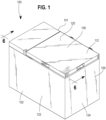
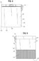
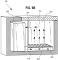
- Figures 1-5 , 6B-6E , 7 and 8A-8F show embodiments being useful for understanding the invention, which are outside the subject-matter of the claims.
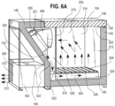
- Figure 6A shows an embodiment according to the present invention, which disclose a cooling system according to claim 1.
- cooling systems may contain components made of several different materials. Additionally, the components may be formed by various forming methods.
- the cooling system 100 generally includes a housing 101, and as will be discussed in more detail below, an internal cooling chamber 200, and a refrigeration system 300.
- the cooling system 100 is configured to cool a plurality of containers including, for example, beverage containers such as soda bottles, water bottles, tetrapacks, beverage cans and other similar beverage and/or food containers including any related packaging. It is understood, however, that the cooling system 100 can be configured to cool other items.
- the cooling system 100 can have a housing 101 having a generally rectangular box shape including a front side 102, a back side 104, a top side 106, a bottom side 108 and two sidewalls 109, 110.
- the housing 101 shown in FIG. 1 is a rectangular box shape, any other suitable housing shapes and sizes can be used, such as, a pyramid shape, spherical shape, and cylinder shape.
- the cooling system housing 101 can include outer walls 120, 122, 124, 126, 128, as shown for example in FIGS. 1-5 .
- the outer walls can be constructed of any suitable materials including, for example, sheet metal, plastics and /or composites.
- the housing 101 can be in the range of about 400 mm to about 700 mm tall; in the range of about 300 mm to about 600 mm deep; and in the range of about 600 mm to about 900 mm wide.
- the outer dimensions of the housing can define a volume of, for example, in the range of about 0.14m 3 to about 0.24 in 3 .
- the above dimensions are provided only as an example.
- the housing can be any suitable size and shape.
- the cooling system 100 also includes an access door 112 for providing access to one or more interior chambers of the cooling system 100.
- the top side 106 includes an access door 112 hingedly connected to the back side 104 of the housing 101 for providing selective access to one or more interior chambers of the cooling system 100. While the door 112 shown in FIG. 1 is shown connected to the back side 104 using hinges 114, any other system can be used to provide access to the interior of the cooling system 100. In some embodiments, for example, the door 112 can be slidably connected to portions of the housing 101, and in other embodiments the door 112 may not be structurally connected to the housing 101 and may simply be removable.
- the door 112 can form a substantial portion, or in some cases more than 50%, of the top side 106 of the housing. In other embodiments the door 112 can be larger or smaller or any size suitable to provide access to an interior portion of the cooling system 100. Additionally, in other embodiments, the door 112 can also be included on any other surface of the housing 101. For example, in some embodiments a door 112 can alternatively be included on the front 102, back 104, or sides 109, 110 of the housing. In still other embodiments, the cooling system 100 may include multiple access doors 112. Such multiple access doors 112 may provide multiple ways to access a single internal compartment or may provide access to multiple internal compartments.
- the door 112 can also include a gasket 113 that forms a seal between the door 112 and the remainder of the housing 101 and acts to restrict heat from outside of the cooling system 100 from entering the cooling system 100.
- the gasket can be manufactured of rubber or any other material suitable for forming a seal between the door and the remainder of the cooling system 100.
- the access door 112 and connection mechanisms discussed herein are provided merely as examples, and any suitable access door 112 and/or mechanism to connect the door 112 to the housing 101 can be used.
- the cooling system 100 also includes insulation 140 between the cool area 150 of the cooling system 100 and the outside environment, including warmer areas 152 of the cooling system 100.
- the insulation material 140 can be any suitable material.
- the insulation 140 is a low cost material such as polyurethane foam, but any other suitable materials can be used such as polystyrene foam.
- the door 112 includes insulation material 140 throughout the entire door which may increase the efficiency of the cooling system 100.
- the door may be composed at least partially of glass or other similar material such that a user can see through the door to the interior of the cooling system 100.
- the cooling system 100 includes at least one interior cooling chamber 200.
- the cooling chamber 200 is defined by surfaces such as a top wall 202 (which as shown in FIGS. 6A and 7 can be an interior wall of the door 112), a bottom wall 205, and sidewalls 206, 208, 210, 212.
- the cooling chamber 200 also includes a surface or floor 204 that is substantially horizontal and is configured to hold a product to be cooled.
- the surface or floor 204 can include a one or more openings, or a plurality of openings, to permit air flow through the bottom of the cooling chamber 200.
- the surfaces, such as, interior walls 202, 205, 206, 208, 210, 212 of the chamber 200 can be constructed of any suitable material such as sheet metal or plastic.
- the bottom wall 205 may be made at a slight angle relative to the horizontal direction and may be operably associated with a drain 215. Any liquid which falls through the floor 204 to the bottom wall 205 can be forced through gravity towards the drain 215 which can have an outlet on the exterior of the cooling system 100.
- the interior cooling chamber 200 used for cooling a product defined by the top wall 202, sidewalls 206, 208, 210, 212, and the surface or floor 204 in some examples can be in the range of about 200 mm to about 600 mm tall, in the range of about 200 mm to about 600 mm deep, and in the range of about 200 mm to about 600 mm wide.
- the cooling chamber 200 can define a volume of, for example, in the range of about 0.008 m 3 to about 0.22 m 3 .
- the above dimensions of the interior cooling chamber 200 are provided only as an example.
- the cooling chamber 200 discussed herein can be any suitable size and shape.
- the cooling system 100 can include more than one cooling chamber 200.
- the cooling chamber 200 can include multiple cooling chambers 200 each having a separate access door 112.
- each separate cooling chamber 200 can be configured to cool products to the same temperature or different temperatures as the other chambers, and at the same cooling rate or different cooling rate as the other cooling chambers.
- one or more cooling chambers can be shut off such that no cooling air flows to that cooling chamber. In some embodiments, this may increase the overall efficiency of the cooling system.
- the cooling system 100 also includes a refrigeration system 300 used to cool the cooling chamber 200.
- the refrigeration system 300 can be located within the housing 101. In some embodiments the refrigeration system can be separate from the cooling chamber 200 and in other embodiments portions of the refrigeration system 300 can be separate from the cooling chamber 200. In still other embodiments, portions of the refrigeration system 300 can be separate from the housing 101.
- the cooling system according to claim 1 includes a compressor, condenser, and evaporator.
- the refrigeration system 300 includes a compressor 302, a condenser 304 and an evaporator 306.
- the compressor 302 and condenser 304 as shown in FIG. 6A are located outside or separate from the cooling chamber 200 and can be located in fluid communication with ambient air outside of the cooling system 100.
- the evaporator 306 is located outside of the cooling chamber 200 but in fluid communication with cooling chamber 200.
- the refrigeration system 300 shown in FIG. 6A , contains a refrigerant, which is usually a fluid.
- the refrigerant can be any material sufficient for use in a refrigeration cycle. This can include materials such as ammonia, sulfur dioxide, and propane.
- the refrigerant In a typical refrigeration cycle the refrigerant generally arrives at the compressor 302 as a cool, low-pressure gas.
- the compressor 302 compresses the refrigerant raising the temperature of the refrigerant.
- the refrigerant then generally exits the compressor 302 as a hot, high pressure gas and flows into the condenser 304.
- the condenser 304 can include a condenser fan 310 that can be used to direct air over the condenser 304 and direct warm air 312 out of the cooling system 100.
- the warm air 312 can exit the cooling system housing 101 through a vent 313 in one or more of the outer walls 120, 122, 124, 126, 128, 130 of the housing 101.
- the refrigerant then flows to the evaporator 306 where it can change from a liquid to a gas. This process can reduce the temperature of the refrigerant, thus cooling the evaporator 306.
- the evaporator 306 may include a plurality of coils and/or fins or other heat sink devices that can improve the efficiency of the evaporator 306.
- the refrigeration system 300 includes a fan 308.
- the fan 308 can be upstream of the evaporator as shown in FIG. 6A or down downstream of the evaporator, and is used to draw (or in some embodiments, push) air 314 from the cooling chamber 200 and direct air over the evaporator 306, thus cooling the air 314.
- the fan 308 also directs cool air 318 out of the evaporator 306 and back into the cooling chamber 200.
- the cooling system 100 includes an air intake vent 320 positioned in an upper portion of the cooling chamber 200.
- the intake vent 320 can be centered at least in the top 50% of the cooling chamber 200, or at least in the top 33% of the cooling chamber 200, or at least in the top 25% of the cooling chamber 200, or at least in the top 10% of the cooling chamber.
- the intake vent 320 acts as an exhaust or discharge vent.
- the intake vent 320 can be a circular opening having a diameter in the range of about 100 mm to about 140 mm. In other embodiments the intake vent 320 can be any other suitable size or shape including square, rectangular shapes, oval and other shapes. In some embodiments, the intake vent 320 can include a screen 321 or other device restricting particles and other objects from accessing the fan 308 from the cooling chamber 200.
- the fan 308 pulls (or in some embodiments, pushes) air 314 through the evaporator (or other cold surface) 306 which cools the air.
- the cool air 318 is then directed through a duct 322.
- the direction of air flow can be reversed.
- the duct 322 can have a substantially vertical section 323 wherein air from the evaporator 306 travels in a substantially vertical downward direction adjacent to the cooling chamber 200, and a substantially horizontal section 324 wherein air from the evaporator 306 travels in a substantially horizontal direction below the cooling chamber 200.
- the substantially vertical portion of the duct 322 can be defined by a rear wall 325, a forward wall 326, and sidewalls 327 and 328.
- the forward wall 326 can be the opposite side of an internal wall 210 of the cooling chamber 200 as shown in FIG. 6 .
- the rear wall 325 can include one or more portions that are inclined and not substantially vertical.
- the sidewalls 327 and 328 can define the width of the duct 322. The width may, in some embodiments, be similar to the width of the cooling chamber 200, but in other embodiments the width may be greater than or less than the width of the cooling chamber.
- the substantially horizontal portion 324 of the duct 322 passes under the cooling chamber 200.
- the substantially horizontal portion 324 of the duct 322 can be defined by sidewalls 327, 328, the bottom wall 205 and a bottom side of the floor 204.
- the duct 322 can also include one or more mechanisms to affect the flow of air within the duct 322.
- the duct 322 can include one or more baffles 325.
- the baffles 325 as shown in FIG. 7 are arranged in the direction of air flow and can act to separate the flow of air within the duct 322.
- the baffles are located between the floor 204 and the bottom wall 205; however baffles 325 may be placed at any location within the duct 322.
- the baffles 325 can be constructed of any suitable material such as sheet metal or plastic.
- the duct 322 has a generally rectangular cross-sectional shape. However, in other embodiments, the duct 322 may have other cross-sectional shapes, such as circular. In still other embodiments, there may be, two or more ducts to direct cool airflow from the evaporator 306 to the cooling chamber 200. In still other embodiments, the duct 322 may have any other suitable size, shape, and/or configuration.
- the surface or floor 204 includes a one or more openings or a plurality of openings 326.
- the openings 326 can be configured such that the airflow from the duct 322, or refrigeration system 300, through each individual opening of the plurality of openings 326 is substantially similar. In embodiments of the cooling system 100 described herein air flow across the entire cross-section of the cooling chamber 200 may be substantially equal. Additionally, the openings 326 and/or floor 204 can be configured such that there is uniform temperature distribution within the cooling chamber 200 which can uniformly cool packages or containers within the cooling chamber 200 to substantially uniform temperatures.
- Substantially equal airflow through each of the openings 326 can be accomplished by varying characteristics of the openings 326 such as the opening size, shape, and spacing arrangement, and through use of the baffles 325 to channel the flow of air within the duct 322.
- the openings 326 can have varying sizes, shapes, and/or locations or spacing arrangements such that the air flow through each of the plurality of openings is substantially similar.
- the openings 326 can be spaced in a grid pattern and each of the openings can be substantially circular in shape.
- a first portion 328 of the plurality of the openings 326 can have a first size, shape, and/or spacing arrangement and a second portion of the openings 330, which is downstream in the direction of air flow of the first portion, can have a second size, shape, and/or spacing arrangement.
- the shape of the openings 326 in the first and second portions 328, 330 can be similar, but in other embodiments the shape of the openings 326 of the first and second portions can be different. As shown in FIG.
- the size of the openings 326 in the first and second portions 328, 330 can be different.
- the openings 326 in the first portion 328 can be smaller than the openings 326 in the second portion 330.
- the first portion of openings 328 can have a diameter of about 16 mm or in the range of about 12 mm to 20 mm and the second portion of openings 330 can have a diameter of about 20 mm or in the range of about 16 mm to about 24 mm.
- the spacing arrangement of the plurality of openings 326 in each of the first and second portions can be similar or can be different.
- the plurality of openings 328 in the first portion may be spaced closer together or further apart than the plurality of openings 330 in the second portion.
- the openings 326 in the surface or floor 204 can have other sizes, shapes, and/or locations that can provide substantially similar air flow through each of the plurality of openings 326.
- these surfaces or floors 204 can be configured such that there is uniform temperature distribution within the cooling chamber 200 which can uniformly cool packages or containers within the cooling chamber 200 to substantially uniform temperatures.
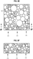
- the plurality of openings can be circular having a different arrangement and different sizes than that shown in FIG. 8A .
- the plurality of openings can have different shapes, sizes, and configurations. As shown in Fig.
- the plurality of openings can be square or rectangular shaped, and as shown, for example in FIG. 8D , the plurality of openings 324 can be hexagonal shaped. Any other suitable shapes can be used including, for example, triangular openings, and octagonal openings. Similarly, any suitable spacing arrangement and sized openings 326 can be used.
- the floor 204 can have a thickness greater than that shown in, for example, FIG. 6A .
- the floor 204 can include a packed bed.
- the packed bed can be composed of any suitable material such that air 318 can flow through the packed bed. Similar to the floors 204 discussed above, the packed bed includes openings 326 through which air 318 from the refrigeration system 300 can flow. Cool air flow 318 through the packed bed can be uniform and can result in uniform temperature distribution within the cooling chamber 200.
- the plurality of openings 326 can be adjustable. Adjustable openings may be used to adjust the cooling system 200 depending on the type and/or size of item to be cooled. For example soda cans may be cooled more efficiently with a floor 204 having openings 326 which are smaller and/or more closely spaced together than a floor 204 used for soda bottles.
- the floor 204 may be removably engaged within the cooling chamber 200 such that a user could install a first floor 204 suited to cool a first product or install a separate second floor 204 when cooling a second product.
- the floor opening configuration may be adjustable within the cooling system 100.
- the floor 204 may be comprised of a first piece and a second piece that are slidably engaged with each piece having a plurality of openings. In such a configuration movement of one of the floor pieces can open, close, enlarge, or decrease the size of the plurality of openings 326 through which air can pass. The opening pattern can thus be adjusted to provide the most efficient air flow possible.
- the adjustment of the floor openings 326 can be manual or automatic.
- a user can manually slide one of the first and second floor pieces.
- the cooling system 100 may include one or more sensors to that can determine the optimum floor arrangement and adjust the floor to the optimum floor arrangement.
- cooling system 100, cooling chamber 200, and refrigeration system 300 can be any suitable size and shape.
- the refrigeration system 300 includes a compressor, condenser, and evaporator.
- Other embodiments of the cooling system 100 are schematically shown in FIGS. 6B-6E .
- the refrigeration system 300 can be any system suitable for providing cooling air flow 318 to the cooling chamber 200. As discussed above, the refrigeration system 300 is a compressor based cooling system as shown in FIG. 6A .
- cooling airflow 318 can exit the refrigeration system 300 and enter the cooling chamber 200 in an upper portion of the cooling chamber 200. The cooling air 318 can then flow in a generally downward direction through the openings 326 in the floor 204 and return to the refrigeration system 300.
- the cooling system 100 can include one or more openings or a plurality of openings 326 in one or more surfaces including sidewalls 206, 208, 210, 212 through which cool air flow 318 from the refrigeration system 300 can flow.
- cool airflow 318 through the openings 326 in the floor 204 and openings 326 in the sidewalls 206, 208, 210, 212 may be substantially similar which can allow for uniform temperature distribution in the cooling chamber 200.
- cool airflow 318 through the one or more openings 326 in the at least one sidewall can be substantially similar which can allow for uniform temperature distribution in the cooling chamber 200.
- the cooling system 100 can have any other suitable size and/or configuration.
- the cooling chamber 200 can, for example, be located above the refrigeration system 300. Cool air 318 from the refrigeration system 300 can flow upwards or downwards through the floor 204 and return to the refrigeration system through an inlet in the cooling chamber 200.
- the cooling system 100 can also include a temperature sensor 402 (not shown), for measuring temperature inside the cooling system 100.
- the refrigeration system 300 can be controlled based on the temperature sensed by the temperature sensor 402. For example, the refrigeration system 300 can turn on when the temperature sensor 402 senses a temperature that is too high and tum off when the temperature sensor 402 senses that a set point temperature has been reached.
- the set point temperature may be in a range of about 10 °C to about 0 °C. Automatic control of the refrigeration system 300 using a temperature sensor 402 can, in some embodiments, improve the efficiency of the cooling system.
- the cooling system 100 can include a logo or other design on one or more of the outer walls 120, 122, 124, 126, 128.
- the logo or other design can include one or more lights, such as, a light-emitting diode (LED).
- the lights or LEDs can surround a logo or other design. The lights or LEDs may be turned on or off and in some embodiments may flash in particular patterns. For example, in one embodiment the lights or LEDs may surround the logo or other design and may be turned on for a first period of time, blink for a second period of time, and certain portions may be turned on while certain portions are turned off during a third period of time.
- the first period of time may be about 15 seconds or in the range of about 10 to 30 seconds
- the second period of time may be about 15 seconds or in the range of about 10 to 30 seconds
- the third period of time may be about 15 seconds or in the range of about 10 to 30 seconds. This sequence can be repeated. Additionally, in other embodiments, the first period of time, second period of time, and third period of time may occur in any order.
- Cooling systems 100 as described herein provide several advantages.
- a cooling system as described herein can significantly reduce the time to cool a product within the cooling system 100.
- cooling systems as described herein can cool beverage bottles from a range of about 50 °C to 30 °C to a range of about 10 °C to 0 °C in about 3 to 6 hours.
- cooling systems 100 as described herein can cool products at least five times faster than other cooling systems.
- cooler systems introduce cool air from an evaporator or other cold surface toward the top of a cooling chamber and intake air to an evaporator or other cold surface through a vent toward the bottom of the cooling chamber.
- Cooling systems described herein intake air to an evaporator or other cold surface from a top portion of the cooling chamber 200 and force cool air through the floor 204 of the cooling chamber. Forcing cool air to move from the bottom to the top of the cooling chamber, against its natural flow, can increase the contact time the cool air has with a product within the cooling chamber 200 and can increase the cooling efficiency of the cooling system 100.
- Cooling systems 100 as discussed herein can reduce the amount of time required to cool a product by at least 15%, or at least 20%, or at least 25% compared to a cooling system that introduces cool air in an upper portion of a cooling chamber.
- the direction of airflow can be reversed such that cool air enters through a vent in the cooling chamber and is pushed out of the floor of the cooling chamber.
- cooling systems described herein can retain the temperature within the cooling chamber after the refrigeration system is turned off better than current cooling systems.
- the cooling system 100 may warm at substantially lower rate compared to a normal cooler.
- the cooling systems described herein may warm the product only to 10 °C to 15 °C after six hours without turning on the refrigeration system.
- the cooling system 100, portions of the cooling chamber 200 include a phase change material.
- phase materials are known including salt hydrates, fatty acids, esters, paraffins, and ionic liquids. Phase change materials are generally encapsulated within a pouch, bag, or similar enclosure. When the refrigeration system 300 is active the phase change material can be allowed to cool and/or freeze.
- the phase change material can help to retain the cool temperature within the cooling system 100 by absorbing heat as the phase change material changes from a solid to a liquid.
- the phase change material is incorporated into any portion of the cooling chamber including into the top wall 202, bottom wall 205, sidewalls 206, 208, 210, 212, and/or floor 204.
- Use of a phase change material in the cooling chamber 200 increases the ability of the cooling system 100 to retain a cool temperature without use of the refrigeration system 300.
- the cooling systems as described herein can reduce operating costs for the same amount of product throughput very significantly compared to existing cooling systems by reducing the electricity usage of the cooling system. Additionally, because of its simplified structure and operation, the cooling system 100 is less expensive to fabricate, operate and maintain.
Landscapes
- Engineering & Computer Science (AREA)
- Physics & Mathematics (AREA)
- Thermal Sciences (AREA)
- Chemical & Material Sciences (AREA)
- Combustion & Propulsion (AREA)
- Mechanical Engineering (AREA)
- General Engineering & Computer Science (AREA)
- Devices That Are Associated With Refrigeration Equipment (AREA)
- Cold Air Circulating Systems And Constructional Details In Refrigerators (AREA)
Claims (13)
- Kühlsystem (100), umfassend:eine Kühlkammer (200), die von Seitenwänden (206, 208, 210, 212) definiert ist,einen Boden (204) und eine obere Wand (202), wobei mindestens eine Fläche der Kühlkammer eine oder mehrere Öffnungen (326) definiert und eingerichtet ist, um mindestens einen Behälter zu halten;wobei das Kühlsystem (100) ferner ein Phasenwechselmaterial umfasst, das in mindestens einer der Seitenwände (206, 208, 210, 212), dem Boden (204) oder der oberen Wand (202) der Kühlkammer angeordnet ist; undwobei das Kühlsystem (100) ferner eine Kühlanlage (300) umfasst, die eingerichtet ist, um die Kühlkammer (200) zu kühlen, indem ein kalter Luftstrom durch die eine oder die mehreren Öffnungen (326) gezwungen wird, wobei die Kühlanlage (300) ferner einen Kondensator (304) umfasst, der seitlich benachbart zu der Kühlkammer (200) an einer vertikalen Wand angeordnet ist, die einen Kaltluftkanal (322) definiert, der eingerichtet ist, um die Kühlanlage und die Öffnungen (326) in Fluidverbindung zu bringen,wobei der Kaltluftkanal (322) zwischen dem Kondensator (304) und der Kühlkammer (200) angeordnet ist, wobei die Kühlanlage (300) ferner einen Verdichter (302) und einen Verdampfer (306) umfasst, der oberhalb einer Ebene angeordnet ist, die von dem Boden definiert ist, und derart positioniert ist, dass sich die mindestens eine Seitenwand zwischen dem Verdampfer (306) und der Kühlkammer (200) befindet,wobei die Kühlanlage (300) ferner einen Ventilator (310) und eine Lufteinlassöffnung (320) in einem oberen Abschnitt der Kühlkammer (200) umfasst, wobei die Lufteinlassöffnung in der mindestens einen Seitenwand angeordnet ist, wobei der Kaltluftkanal (322) einen im Wesentlichen vertikalen Abschnitt, der zumindest teilweise benachbart zu der Kühlkammer (200) angeordnet ist, und einen im Wesentlichen horizontalen Abschnitt aufweist, der zumindest teilweise unterhalb der Fläche angeordnet ist, wobei die Kühlanlage (30) eingerichtet ist, um die Kühlkammer (200) zu kühlen, indem ein kalter Luftstrom durch den Kaltluftkanal (322) und durch die eine oder mehreren Öffnungen (326) gezwungen wird, undwobei das Phasenwechselmaterial eingerichtet ist, um eine gewünschte Temperatur in der Kühlkammer aufrechtzuerhalten, wenn das Kühlsystem nicht in Betrieb ist.
- Kühlsystem (100) nach Anspruch 1, wobei der Luftstrom durch jede der einen oder mehreren Öffnungen (326) im Wesentlichen ähnlich ist.
- Kühlsystem (100) nach Anspruch 2, wobei das Kühlsystem (100) eingerichtet ist, um eine im Wesentlichen gleichmäßige Temperaturverteilung in der Kühlkammer (200) bereitzustellen.
- Kühlsystem (100) nach Anspruch 2, wobei die mindestens eine Fläche die mindestens eine Seitenwand umfasst.
- Kühlsystem (100) nach Anspruch 2, wobei jede der einen oder mehreren Öffnungen (326) so bemessen ist, dass sie einen im Wesentlichen ähnlichen Luftstrom durch sie hindurch bereitstellt.
- Kühlsystem (100) nach Anspruch 2, wobei jede der einen oder mehreren Öffnungen (326) so geformt ist, dass sie einen im Wesentlichen ähnlichen Luftstrom durch sie hindurch bereitstellt.
- Kühlsystem (100) nach Anspruch 2, wobei jede der Öffnungen (326) so platziert ist, dass sie einen im Wesentlichen ähnlichen Luftstrom durch sie hindurch bereitstellt.
- Kühlsystem (100) nach Anspruch 1, wobei die mindestens eine Fläche ein gepacktes Bett umfasst.
- Kühlsystem (100) nach Anspruch 2, wobei mindestens einige der einen oder mehreren Öffnungen (326) kreisförmig sind.
- Kühlsystem (100) nach einem der vorhergehenden Ansprüche, ferner umfassend eine oder mehrere Leitbleche (325), die sich in dem Kaltluftkanal (322) befinden, wobei das eine oder die mehreren Leitbleche (325) eingerichtet sind, um den Luftstrom innerhalb des Kaltluftkanals (322) anzupassen.
- Kühlsystem (100) nach Anspruch 10, wobei der im Wesentlichen vertikale Abschnitt des Kaltluftkanals (322), der zumindest teilweise benachbart zur Kühlkammer (200) angeordnet ist, die Kühlkammer (200) von dem Kondensator (304) trennt.
- Kühlsystem (100) nach Anspruch 2, wobei das Kühlsystem (100) eingerichtet ist, um Getränkeflaschen in der Kühlkammer (200) von einem Bereich von etwa 30 °C bis 50 °C auf einen Bereich von etwa 10 °C bis 0 °C in 1,5 bis 6 Stunden zu kühlen.
- Kühlsystem (100) nach Anspruch 1, wobei die Fläche ferner mindestens einen ersten Bereich mit einer oder mehreren Öffnungen (326) mit mindestens einem ersten Öffnungsmerkmal und einen zweiten Bereich mit einer oder mehreren Öffnungen (326) mit mindestens einem zweiten Öffnungsmerkmal, das sich vom ersten Öffnungsmerkmal unterscheidet, aufweist, wobei die Fläche eingerichtet ist, um mindestens einen Behälter zu halten;
wobei der Luftstrom durch jede der einen oder mehreren Öffnungen (326) im Wesentlichen ähnlich ist.
Applications Claiming Priority (2)
| Application Number | Priority Date | Filing Date | Title |
|---|---|---|---|
| IN763DE2015 | 2015-03-20 | ||
| PCT/US2016/022867 WO2016153919A1 (en) | 2015-03-20 | 2016-03-17 | Cooling system and method |
Publications (3)
| Publication Number | Publication Date |
|---|---|
| EP3270740A1 EP3270740A1 (de) | 2018-01-24 |
| EP3270740A4 EP3270740A4 (de) | 2018-10-31 |
| EP3270740B1 true EP3270740B1 (de) | 2025-05-07 |
Family
ID=56978405
Family Applications (1)
| Application Number | Title | Priority Date | Filing Date |
|---|---|---|---|
| EP16769371.2A Active EP3270740B1 (de) | 2015-03-20 | 2016-03-17 | Kühlsystem |
Country Status (14)
| Country | Link |
|---|---|
| US (2) | US20180209716A1 (de) |
| EP (1) | EP3270740B1 (de) |
| JP (1) | JP6732780B2 (de) |
| CN (1) | CN107427137B (de) |
| AR (1) | AR104023A1 (de) |
| AU (1) | AU2016235797B2 (de) |
| BR (1) | BR112017019732A2 (de) |
| CA (1) | CA2978666C (de) |
| ES (1) | ES3032666T3 (de) |
| HK (1) | HK1243898A1 (de) |
| MX (1) | MX2017011975A (de) |
| PL (1) | PL3270740T3 (de) |
| RU (1) | RU2721856C2 (de) |
| WO (1) | WO2016153919A1 (de) |
Families Citing this family (6)
| Publication number | Priority date | Publication date | Assignee | Title |
|---|---|---|---|---|
| GB2578792B (en) * | 2018-11-09 | 2021-07-14 | Kaelo Tech Ltd | Cooling device |
| US20200224965A1 (en) * | 2019-01-11 | 2020-07-16 | Zhongshan Candor Electric Appliances Co., Ltd. | Wine cooler capable of reducing power consumption |
| US11542147B2 (en) * | 2019-09-30 | 2023-01-03 | Marmon Foodservice Technologies, Inc. | Beverage dispensers with heat exchangers |
| USD947257S1 (en) * | 2019-10-11 | 2022-03-29 | Hefei Hualing Co., Ltd. | Refrigerator |
| EP4211408B1 (de) * | 2020-09-11 | 2025-11-26 | Autostore Technology AS | System zur temperatursteuerung in einem automatisierten lagersystem |
| CN113983741A (zh) * | 2021-12-01 | 2022-01-28 | 上海理工大学 | 一种高冷量利用率的低温箱 |
Citations (6)
| Publication number | Priority date | Publication date | Assignee | Title |
|---|---|---|---|---|
| JP2003254659A (ja) * | 2002-02-26 | 2003-09-10 | Mitsubishi Heavy Ind Ltd | コンテナ用冷凍装置 |
| US6763677B1 (en) * | 2003-10-20 | 2004-07-20 | Carrier Corporation | Fresh air vent position monitoring system |
| WO2011007960A2 (en) * | 2009-07-15 | 2011-01-20 | Lg Electronics Inc. | Refrigerator |
| JP2013011420A (ja) * | 2011-06-30 | 2013-01-17 | Daikin Industries Ltd | コンテナ用冷凍装置 |
| CN103625781A (zh) * | 2012-08-23 | 2014-03-12 | 派利肯生物制药有限公司 | 热管理系统和方法 |
| GB2514622A (en) * | 2013-05-31 | 2014-12-03 | New Wave Innovation Ltd | Improvements to a refrigerator that uses a phase change material as a thermal store |
Family Cites Families (40)
| Publication number | Priority date | Publication date | Assignee | Title |
|---|---|---|---|---|
| US2013264A (en) * | 1933-04-08 | 1935-09-03 | Charles G Buder | Cooling packaged materials |
| US2162923A (en) * | 1938-03-05 | 1939-06-20 | Herbert H Short | Refrigerator air circulating and purifying means |
| US2241558A (en) * | 1938-09-09 | 1941-05-13 | Roland S Read | Air-cooled bottled beverage cooler |
| US2203991A (en) * | 1939-06-15 | 1940-06-11 | Andrew J Johnson | Beverage cooler |
| US2275323A (en) * | 1940-05-29 | 1942-03-03 | Gen Motors Corp | Refrigerating apparatus |
| US3299664A (en) * | 1965-09-23 | 1967-01-24 | John S Booth | Forced draft refrigerator |
| US3521459A (en) * | 1968-06-21 | 1970-07-21 | Eric Rath | Method for storing and transporting food in a fresh condition |
| US3712078A (en) * | 1971-11-22 | 1973-01-23 | Krispin Eng Ltd | Refrigeration unit |
| US3984163A (en) * | 1975-12-22 | 1976-10-05 | General Electric Company | Cantilever sliding shelf including a shelf removal notch on one side only |
| US4308726A (en) * | 1979-01-31 | 1982-01-05 | Tyler Refrigeration Corporation | Open top refrigerated display case with storage section |
| US4462220A (en) * | 1981-10-30 | 1984-07-31 | Gerlach Industries | Cooling sensor for refrigeration system |
| US4977754A (en) * | 1990-05-01 | 1990-12-18 | Specialty Equipment Companies, Inc. | Next-to-be-purchased cold beverage merchandiser |
| GB2301172B (en) * | 1993-03-13 | 1997-11-26 | Chilla Limited | Improvements in or relating to cooling equipment |
| US5357767A (en) * | 1993-05-07 | 1994-10-25 | Hussmann Corporation | Low temperature display merchandiser |
| NO300344B1 (no) * | 1996-03-13 | 1997-05-12 | Jan Egil Floeysvik | Kjöledisk |
| EP0895043A3 (de) * | 1997-07-31 | 1999-10-13 | Samsung Electronics Co., Ltd. | Kühlschrank |
| JP4341093B2 (ja) * | 1999-01-13 | 2009-10-07 | 株式会社デンソー | 空調装置 |
| WO2000070279A1 (en) * | 1999-05-19 | 2000-11-23 | Robert Thorne Lawrence | Cooling unit |
| US6532749B2 (en) * | 1999-09-22 | 2003-03-18 | The Coca-Cola Company | Stirling-based heating and cooling device |
| US6955061B2 (en) * | 2000-05-18 | 2005-10-18 | Carrier Corporation | Refrigerated merchandiser with flow baffle |
| US6422031B1 (en) * | 2001-08-15 | 2002-07-23 | Maytag Corporation | Refrigeration appliance with impingement cooling system |
| RU2221972C2 (ru) * | 2002-02-04 | 2004-01-20 | Закрытое акционерное общество "Завод холодильников Стинол" | Холодильник |
| AU2003210344A1 (en) * | 2002-03-28 | 2003-10-13 | Unilever Plc | Method for dispensing frozen edible products and insulated container adapted therefore |
| US20050241333A1 (en) * | 2003-12-03 | 2005-11-03 | Hamilton Robert W | Rate-controlled freezer and cooling methods thereof |
| US7451603B2 (en) * | 2004-03-22 | 2008-11-18 | General Mills, Inc. | Portable cooled merchandizing unit |
| JP2005274031A (ja) * | 2004-03-25 | 2005-10-06 | Gac Corp | 収納装置 |
| EP1878986A1 (de) * | 2005-04-27 | 2008-01-16 | Fukushima Kogyo Co., Ltd. | Kühlvorrichtung |
| DE202006010757U1 (de) * | 2006-07-11 | 2006-11-02 | Sgl Carbon Ag | Kühlvorrichtung |
| US20100050665A1 (en) * | 2007-08-13 | 2010-03-04 | B/E Aerospace, Inc. | Method and apparatus for maintaining a uniform temperature in a refrigeration system |
| US20110127273A1 (en) * | 2007-12-11 | 2011-06-02 | TOKITAE LLC, a limited liability company of the State of Delaware | Temperature-stabilized storage systems including storage structures configured for interchangeable storage of modular units |
| CN101910760B (zh) * | 2008-03-14 | 2013-03-13 | 创新制冷系统有限公司 | 主动冷却型瓶子座架 |
| US9572436B2 (en) * | 2008-07-22 | 2017-02-21 | Pepsico, Inc. | Cooler merchandiser with customizable graphics |
| HK1137899A2 (zh) * | 2009-06-05 | 2010-08-06 | Ace Action Limited | 节能装置、空调或制冷系统及空调或制冷系统的控制方法 |
| KR101071968B1 (ko) * | 2009-07-17 | 2011-10-11 | 금오공과대학교 산학협력단 | 상변화물질을 이용한 에너지 저감 냉장고 |
| US8474274B2 (en) * | 2010-05-11 | 2013-07-02 | The Boeing Company | Refrigerated container |
| JP2012007865A (ja) * | 2010-06-28 | 2012-01-12 | Hitachi Plant Technologies Ltd | 冷却システム |
| EP2593730B1 (de) * | 2010-07-13 | 2018-12-19 | LG Electronics Inc. | Kühlvorrichtung und kühlschrank damit |
| US20120129443A1 (en) * | 2010-10-06 | 2012-05-24 | Philip Bastow | Airflow and Heating Control Supply Air Terminal |
| GB2501223B (en) * | 2012-01-05 | 2017-05-03 | Mars Inc | Cool storage cabinet |
| JP5971296B2 (ja) * | 2014-09-16 | 2016-08-17 | ダイキン工業株式会社 | コンテナ用冷凍装置 |
-
2016
- 2016-03-17 JP JP2017546939A patent/JP6732780B2/ja active Active
- 2016-03-17 US US15/558,492 patent/US20180209716A1/en not_active Abandoned
- 2016-03-17 ES ES16769371T patent/ES3032666T3/es active Active
- 2016-03-17 WO PCT/US2016/022867 patent/WO2016153919A1/en not_active Ceased
- 2016-03-17 PL PL16769371.2T patent/PL3270740T3/pl unknown
- 2016-03-17 EP EP16769371.2A patent/EP3270740B1/de active Active
- 2016-03-17 HK HK18103425.9A patent/HK1243898A1/zh unknown
- 2016-03-17 RU RU2017135575A patent/RU2721856C2/ru active
- 2016-03-17 CA CA2978666A patent/CA2978666C/en active Active
- 2016-03-17 CN CN201680016863.5A patent/CN107427137B/zh active Active
- 2016-03-17 AU AU2016235797A patent/AU2016235797B2/en active Active
- 2016-03-17 MX MX2017011975A patent/MX2017011975A/es unknown
- 2016-03-17 BR BR112017019732-4A patent/BR112017019732A2/pt not_active Application Discontinuation
- 2016-03-18 AR ARP160100741A patent/AR104023A1/es unknown
-
2021
- 2021-04-05 US US17/222,513 patent/US20210222943A1/en not_active Abandoned
Patent Citations (6)
| Publication number | Priority date | Publication date | Assignee | Title |
|---|---|---|---|---|
| JP2003254659A (ja) * | 2002-02-26 | 2003-09-10 | Mitsubishi Heavy Ind Ltd | コンテナ用冷凍装置 |
| US6763677B1 (en) * | 2003-10-20 | 2004-07-20 | Carrier Corporation | Fresh air vent position monitoring system |
| WO2011007960A2 (en) * | 2009-07-15 | 2011-01-20 | Lg Electronics Inc. | Refrigerator |
| JP2013011420A (ja) * | 2011-06-30 | 2013-01-17 | Daikin Industries Ltd | コンテナ用冷凍装置 |
| CN103625781A (zh) * | 2012-08-23 | 2014-03-12 | 派利肯生物制药有限公司 | 热管理系统和方法 |
| GB2514622A (en) * | 2013-05-31 | 2014-12-03 | New Wave Innovation Ltd | Improvements to a refrigerator that uses a phase change material as a thermal store |
Also Published As
| Publication number | Publication date |
|---|---|
| AR104023A1 (es) | 2017-06-21 |
| EP3270740A4 (de) | 2018-10-31 |
| CN107427137A (zh) | 2017-12-01 |
| RU2017135575A3 (de) | 2019-09-02 |
| PL3270740T3 (pl) | 2025-09-15 |
| US20180209716A1 (en) | 2018-07-26 |
| AU2016235797A1 (en) | 2017-09-21 |
| CA2978666C (en) | 2024-01-02 |
| HK1243898A1 (zh) | 2018-07-27 |
| CA2978666A1 (en) | 2016-09-29 |
| WO2016153919A1 (en) | 2016-09-29 |
| AU2016235797B2 (en) | 2020-06-11 |
| RU2721856C2 (ru) | 2020-05-25 |
| BR112017019732A2 (pt) | 2018-05-22 |
| RU2017135575A (ru) | 2019-04-22 |
| JP6732780B2 (ja) | 2020-07-29 |
| MX2017011975A (es) | 2018-06-06 |
| EP3270740A1 (de) | 2018-01-24 |
| CN107427137B (zh) | 2022-02-25 |
| US20210222943A1 (en) | 2021-07-22 |
| ES3032666T3 (en) | 2025-07-23 |
| JP2018512069A (ja) | 2018-05-10 |
Similar Documents
| Publication | Publication Date | Title |
|---|---|---|
| US20210222943A1 (en) | Cooling system and method | |
| JP7413328B2 (ja) | 冷蔵商品陳列システム | |
| US10101074B2 (en) | Ice maker air flow ribs | |
| US10619908B2 (en) | Refrigeration cabinet | |
| US7451603B2 (en) | Portable cooled merchandizing unit | |
| US5701754A (en) | Automobile refrigerator | |
| CN104567190B (zh) | 风冷冰箱 | |
| CN106152673A (zh) | 干燥装置以及具备该干燥装置的冰箱 | |
| CN102853609B (zh) | 冷冻冰箱 | |
| CN104879984A (zh) | 冰箱 | |
| WO2016082534A1 (zh) | 风冷冰箱及其控制方法 | |
| CN203203318U (zh) | 分体式组合冰箱 | |
| JP6932256B2 (ja) | 冷蔵庫 | |
| JP2007120942A (ja) | 冷蔵庫 | |
| CN104567197B (zh) | 冰箱 | |
| SI24250A (sl) | Naprava in metoda za temperiranje Ĺľivil | |
| JP3644855B2 (ja) | 冷蔵庫 | |
| EP2796816B1 (de) | Vorrichtung zum Kühlen oder Gefrieren eines Behälters | |
| JP2007120943A (ja) | 冷蔵庫 | |
| EP3006871B1 (de) | Kühlschrank mit einem Fach mit herausnehmbaren Nahrungsmittelbehältern mit kontrollierter Umgebung | |
| CN103868179A (zh) | 一种冷暖空调与冷藏柜的集成化一体机 | |
| CN204594035U (zh) | 制冷设备 | |
| CN208421971U (zh) | 一种无人值守自动食品售货机 | |
| EP3171106B1 (de) | Kühltheke, verwendung einer kühltheke | |
| KR101973727B1 (ko) | 쇼케이스 |
Legal Events
| Date | Code | Title | Description |
|---|---|---|---|
| STAA | Information on the status of an ep patent application or granted ep patent |
Free format text: STATUS: THE INTERNATIONAL PUBLICATION HAS BEEN MADE |
|
| PUAI | Public reference made under article 153(3) epc to a published international application that has entered the european phase |
Free format text: ORIGINAL CODE: 0009012 |
|
| STAA | Information on the status of an ep patent application or granted ep patent |
Free format text: STATUS: REQUEST FOR EXAMINATION WAS MADE |
|
| 17P | Request for examination filed |
Effective date: 20171011 |
|
| AK | Designated contracting states |
Kind code of ref document: A1 Designated state(s): AL AT BE BG CH CY CZ DE DK EE ES FI FR GB GR HR HU IE IS IT LI LT LU LV MC MK MT NL NO PL PT RO RS SE SI SK SM TR |
|
| AX | Request for extension of the european patent |
Extension state: BA ME |
|
| RIN1 | Information on inventor provided before grant (corrected) |
Inventor name: VATS, TANMAYA Inventor name: SOOD, ASHISH Inventor name: JAFA, EMAD Inventor name: JAIN, SANDEEP Inventor name: PARIKH, DEWANG |
|
| DAV | Request for validation of the european patent (deleted) | ||
| DAX | Request for extension of the european patent (deleted) | ||
| A4 | Supplementary search report drawn up and despatched |
Effective date: 20181002 |
|
| RIC1 | Information provided on ipc code assigned before grant |
Ipc: F25D 31/00 20060101ALI20180926BHEP Ipc: F25D 17/08 20060101ALI20180926BHEP Ipc: A47F 3/04 20060101AFI20180926BHEP |
|
| STAA | Information on the status of an ep patent application or granted ep patent |
Free format text: STATUS: EXAMINATION IS IN PROGRESS |
|
| 17Q | First examination report despatched |
Effective date: 20201211 |
|
| REG | Reference to a national code |
Ref country code: DE Ref legal event code: R079 Free format text: PREVIOUS MAIN CLASS: A47F0003040000 Ipc: F25D0003020000 Ref document number: 602016092169 Country of ref document: DE |
|
| GRAP | Despatch of communication of intention to grant a patent |
Free format text: ORIGINAL CODE: EPIDOSNIGR1 |
|
| STAA | Information on the status of an ep patent application or granted ep patent |
Free format text: STATUS: GRANT OF PATENT IS INTENDED |
|
| RIC1 | Information provided on ipc code assigned before grant |
Ipc: F25D 31/00 20060101ALI20241008BHEP Ipc: F25D 3/02 20060101AFI20241008BHEP |
|
| INTG | Intention to grant announced |
Effective date: 20241022 |
|
| GRAS | Grant fee paid |
Free format text: ORIGINAL CODE: EPIDOSNIGR3 |
|
| RIN1 | Information on inventor provided before grant (corrected) |
Inventor name: JAFA, EMAD Inventor name: VATS, TANMAYA Inventor name: SOOD, ASHISH Inventor name: PARIKH, DEWANG Inventor name: JAIN, SANDEEP |
|
| P01 | Opt-out of the competence of the unified patent court (upc) registered |
Free format text: CASE NUMBER: APP_8704/2025 Effective date: 20250220 |
|
| GRAA | (expected) grant |
Free format text: ORIGINAL CODE: 0009210 |
|
| STAA | Information on the status of an ep patent application or granted ep patent |
Free format text: STATUS: THE PATENT HAS BEEN GRANTED |
|
| AK | Designated contracting states |
Kind code of ref document: B1 Designated state(s): AL AT BE BG CH CY CZ DE DK EE ES FI FR GB GR HR HU IE IS IT LI LT LU LV MC MK MT NL NO PL PT RO RS SE SI SK SM TR |
|
| REG | Reference to a national code |
Ref country code: GB Ref legal event code: FG4D |
|
| REG | Reference to a national code |
Ref country code: CH Ref legal event code: EP |
|
| REG | Reference to a national code |
Ref country code: DE Ref legal event code: R096 Ref document number: 602016092169 Country of ref document: DE |
|
| REG | Reference to a national code |
Ref country code: IE Ref legal event code: FG4D |
|
| REG | Reference to a national code |
Ref country code: NL Ref legal event code: FP |
|
| REG | Reference to a national code |
Ref country code: ES Ref legal event code: FG2A Ref document number: 3032666 Country of ref document: ES Kind code of ref document: T3 Effective date: 20250723 |
|
| PG25 | Lapsed in a contracting state [announced via postgrant information from national office to epo] |
Ref country code: PT Free format text: LAPSE BECAUSE OF FAILURE TO SUBMIT A TRANSLATION OF THE DESCRIPTION OR TO PAY THE FEE WITHIN THE PRESCRIBED TIME-LIMIT Effective date: 20250908 Ref country code: FI Free format text: LAPSE BECAUSE OF FAILURE TO SUBMIT A TRANSLATION OF THE DESCRIPTION OR TO PAY THE FEE WITHIN THE PRESCRIBED TIME-LIMIT Effective date: 20250507 |
|
| REG | Reference to a national code |
Ref country code: LT Ref legal event code: MG9D |
|
| PG25 | Lapsed in a contracting state [announced via postgrant information from national office to epo] |
Ref country code: GR Free format text: LAPSE BECAUSE OF FAILURE TO SUBMIT A TRANSLATION OF THE DESCRIPTION OR TO PAY THE FEE WITHIN THE PRESCRIBED TIME-LIMIT Effective date: 20250808 Ref country code: NO Free format text: LAPSE BECAUSE OF FAILURE TO SUBMIT A TRANSLATION OF THE DESCRIPTION OR TO PAY THE FEE WITHIN THE PRESCRIBED TIME-LIMIT Effective date: 20250807 |
|
| REG | Reference to a national code |
Ref country code: AT Ref legal event code: MK05 Ref document number: 1792854 Country of ref document: AT Kind code of ref document: T Effective date: 20250507 |
|
| PG25 | Lapsed in a contracting state [announced via postgrant information from national office to epo] |
Ref country code: BG Free format text: LAPSE BECAUSE OF FAILURE TO SUBMIT A TRANSLATION OF THE DESCRIPTION OR TO PAY THE FEE WITHIN THE PRESCRIBED TIME-LIMIT Effective date: 20250507 |
|
| PG25 | Lapsed in a contracting state [announced via postgrant information from national office to epo] |
Ref country code: HR Free format text: LAPSE BECAUSE OF FAILURE TO SUBMIT A TRANSLATION OF THE DESCRIPTION OR TO PAY THE FEE WITHIN THE PRESCRIBED TIME-LIMIT Effective date: 20250507 |
|
| PG25 | Lapsed in a contracting state [announced via postgrant information from national office to epo] |
Ref country code: AT Free format text: LAPSE BECAUSE OF FAILURE TO SUBMIT A TRANSLATION OF THE DESCRIPTION OR TO PAY THE FEE WITHIN THE PRESCRIBED TIME-LIMIT Effective date: 20250507 |
|
| PG25 | Lapsed in a contracting state [announced via postgrant information from national office to epo] |
Ref country code: RS Free format text: LAPSE BECAUSE OF FAILURE TO SUBMIT A TRANSLATION OF THE DESCRIPTION OR TO PAY THE FEE WITHIN THE PRESCRIBED TIME-LIMIT Effective date: 20250807 |
|
| PG25 | Lapsed in a contracting state [announced via postgrant information from national office to epo] |
Ref country code: IS Free format text: LAPSE BECAUSE OF FAILURE TO SUBMIT A TRANSLATION OF THE DESCRIPTION OR TO PAY THE FEE WITHIN THE PRESCRIBED TIME-LIMIT Effective date: 20250907 |
|
| PG25 | Lapsed in a contracting state [announced via postgrant information from national office to epo] |
Ref country code: LV Free format text: LAPSE BECAUSE OF FAILURE TO SUBMIT A TRANSLATION OF THE DESCRIPTION OR TO PAY THE FEE WITHIN THE PRESCRIBED TIME-LIMIT Effective date: 20250507 |
|
| PG25 | Lapsed in a contracting state [announced via postgrant information from national office to epo] |
Ref country code: SM Free format text: LAPSE BECAUSE OF FAILURE TO SUBMIT A TRANSLATION OF THE DESCRIPTION OR TO PAY THE FEE WITHIN THE PRESCRIBED TIME-LIMIT Effective date: 20250507 Ref country code: DK Free format text: LAPSE BECAUSE OF FAILURE TO SUBMIT A TRANSLATION OF THE DESCRIPTION OR TO PAY THE FEE WITHIN THE PRESCRIBED TIME-LIMIT Effective date: 20250507 |
|
| PG25 | Lapsed in a contracting state [announced via postgrant information from national office to epo] |
Ref country code: CZ Free format text: LAPSE BECAUSE OF FAILURE TO SUBMIT A TRANSLATION OF THE DESCRIPTION OR TO PAY THE FEE WITHIN THE PRESCRIBED TIME-LIMIT Effective date: 20250507 |
|
| PG25 | Lapsed in a contracting state [announced via postgrant information from national office to epo] |
Ref country code: EE Free format text: LAPSE BECAUSE OF FAILURE TO SUBMIT A TRANSLATION OF THE DESCRIPTION OR TO PAY THE FEE WITHIN THE PRESCRIBED TIME-LIMIT Effective date: 20250507 |
|
| PG25 | Lapsed in a contracting state [announced via postgrant information from national office to epo] |
Ref country code: RO Free format text: LAPSE BECAUSE OF FAILURE TO SUBMIT A TRANSLATION OF THE DESCRIPTION OR TO PAY THE FEE WITHIN THE PRESCRIBED TIME-LIMIT Effective date: 20250507 Ref country code: SK Free format text: LAPSE BECAUSE OF FAILURE TO SUBMIT A TRANSLATION OF THE DESCRIPTION OR TO PAY THE FEE WITHIN THE PRESCRIBED TIME-LIMIT Effective date: 20250507 |
|
| REG | Reference to a national code |
Ref country code: DE Ref legal event code: R097 Ref document number: 602016092169 Country of ref document: DE |
|
| PLBE | No opposition filed within time limit |
Free format text: ORIGINAL CODE: 0009261 |
|
| STAA | Information on the status of an ep patent application or granted ep patent |
Free format text: STATUS: NO OPPOSITION FILED WITHIN TIME LIMIT |
|
| REG | Reference to a national code |
Ref country code: CH Ref legal event code: L10 Free format text: ST27 STATUS EVENT CODE: U-0-0-L10-L00 (AS PROVIDED BY THE NATIONAL OFFICE) Effective date: 20260318 |
|
| 26N | No opposition filed |
Effective date: 20260210 |