EP3269443A1 - Entfernung von kohlendioxid aus einer atmosphäre und globaler thermostat - Google Patents
Entfernung von kohlendioxid aus einer atmosphäre und globaler thermostat Download PDFInfo
- Publication number
- EP3269443A1 EP3269443A1 EP17162034.7A EP17162034A EP3269443A1 EP 3269443 A1 EP3269443 A1 EP 3269443A1 EP 17162034 A EP17162034 A EP 17162034A EP 3269443 A1 EP3269443 A1 EP 3269443A1
- Authority
- EP
- European Patent Office
- Prior art keywords
- carbon dioxide
- atmosphere
- air
- medium
- location
- Prior art date
- Legal status (The legal status is an assumption and is not a legal conclusion. Google has not performed a legal analysis and makes no representation as to the accuracy of the status listed.)
- Withdrawn
Links
Images

Classifications
-
- B—PERFORMING OPERATIONS; TRANSPORTING
- B01—PHYSICAL OR CHEMICAL PROCESSES OR APPARATUS IN GENERAL
- B01D—SEPARATION
- B01D53/00—Separation of gases or vapours; Recovering vapours of volatile solvents from gases; Chemical or biological purification of waste gases, e.g. engine exhaust gases, smoke, fumes, flue gases, aerosols
- B01D53/14—Separation of gases or vapours; Recovering vapours of volatile solvents from gases; Chemical or biological purification of waste gases, e.g. engine exhaust gases, smoke, fumes, flue gases, aerosols by absorption
- B01D53/1456—Removing acid components
- B01D53/1475—Removing carbon dioxide
-
- B—PERFORMING OPERATIONS; TRANSPORTING
- B01—PHYSICAL OR CHEMICAL PROCESSES OR APPARATUS IN GENERAL
- B01D—SEPARATION
- B01D53/00—Separation of gases or vapours; Recovering vapours of volatile solvents from gases; Chemical or biological purification of waste gases, e.g. engine exhaust gases, smoke, fumes, flue gases, aerosols
- B01D53/34—Chemical or biological purification of waste gases
- B01D53/46—Removing components of defined structure
- B01D53/62—Carbon oxides
-
- B—PERFORMING OPERATIONS; TRANSPORTING
- B01—PHYSICAL OR CHEMICAL PROCESSES OR APPARATUS IN GENERAL
- B01D—SEPARATION
- B01D2251/00—Reactants
- B01D2251/30—Alkali metal compounds
- B01D2251/304—Alkali metal compounds of sodium
-
- B—PERFORMING OPERATIONS; TRANSPORTING
- B01—PHYSICAL OR CHEMICAL PROCESSES OR APPARATUS IN GENERAL
- B01D—SEPARATION
- B01D2251/00—Reactants
- B01D2251/60—Inorganic bases or salts
- B01D2251/604—Hydroxides
-
- B—PERFORMING OPERATIONS; TRANSPORTING
- B01—PHYSICAL OR CHEMICAL PROCESSES OR APPARATUS IN GENERAL
- B01D—SEPARATION
- B01D2252/00—Absorbents, i.e. solvents and liquid materials for gas absorption
- B01D2252/20—Organic absorbents
- B01D2252/204—Amines
-
- B—PERFORMING OPERATIONS; TRANSPORTING
- B01—PHYSICAL OR CHEMICAL PROCESSES OR APPARATUS IN GENERAL
- B01D—SEPARATION
- B01D2257/00—Components to be removed
- B01D2257/50—Carbon oxides
- B01D2257/504—Carbon dioxide
-
- B—PERFORMING OPERATIONS; TRANSPORTING
- B01—PHYSICAL OR CHEMICAL PROCESSES OR APPARATUS IN GENERAL
- B01D—SEPARATION
- B01D2258/00—Sources of waste gases
- B01D2258/02—Other waste gases
- B01D2258/0233—Other waste gases from cement factories
-
- Y—GENERAL TAGGING OF NEW TECHNOLOGICAL DEVELOPMENTS; GENERAL TAGGING OF CROSS-SECTIONAL TECHNOLOGIES SPANNING OVER SEVERAL SECTIONS OF THE IPC; TECHNICAL SUBJECTS COVERED BY FORMER USPC CROSS-REFERENCE ART COLLECTIONS [XRACs] AND DIGESTS
- Y02—TECHNOLOGIES OR APPLICATIONS FOR MITIGATION OR ADAPTATION AGAINST CLIMATE CHANGE
- Y02C—CAPTURE, STORAGE, SEQUESTRATION OR DISPOSAL OF GREENHOUSE GASES [GHG]
- Y02C20/00—Capture or disposal of greenhouse gases
- Y02C20/40—Capture or disposal of greenhouse gases of CO2
-
- Y—GENERAL TAGGING OF NEW TECHNOLOGICAL DEVELOPMENTS; GENERAL TAGGING OF CROSS-SECTIONAL TECHNOLOGIES SPANNING OVER SEVERAL SECTIONS OF THE IPC; TECHNICAL SUBJECTS COVERED BY FORMER USPC CROSS-REFERENCE ART COLLECTIONS [XRACs] AND DIGESTS
- Y02—TECHNOLOGIES OR APPLICATIONS FOR MITIGATION OR ADAPTATION AGAINST CLIMATE CHANGE
- Y02E—REDUCTION OF GREENHOUSE GAS [GHG] EMISSIONS, RELATED TO ENERGY GENERATION, TRANSMISSION OR DISTRIBUTION
- Y02E20/00—Combustion technologies with mitigation potential
- Y02E20/32—Direct CO2 mitigation
-
- Y—GENERAL TAGGING OF NEW TECHNOLOGICAL DEVELOPMENTS; GENERAL TAGGING OF CROSS-SECTIONAL TECHNOLOGIES SPANNING OVER SEVERAL SECTIONS OF THE IPC; TECHNICAL SUBJECTS COVERED BY FORMER USPC CROSS-REFERENCE ART COLLECTIONS [XRACs] AND DIGESTS
- Y02—TECHNOLOGIES OR APPLICATIONS FOR MITIGATION OR ADAPTATION AGAINST CLIMATE CHANGE
- Y02P—CLIMATE CHANGE MITIGATION TECHNOLOGIES IN THE PRODUCTION OR PROCESSING OF GOODS
- Y02P20/00—Technologies relating to chemical industry
- Y02P20/10—Process efficiency
- Y02P20/133—Renewable energy sources, e.g. sunlight
Definitions
- the present invention relates to systems and methods for removing greenhouse gases from an atmosphere, and in particular to systems and methods for removing carbon dioxide from an atmosphere.
- IPCC Intergovernmental Panel on Climate Change
- C CA (Y N ) represent the carbon dioxide added to the atmosphere in year Y N in gigatonnes per year.
- C EX (Y N ) the amount extracted
- C EM (Y N ) the amount emitted by humans
- C N (Y N ) be the amount either added or removed due to natural variations in the carbon cycle.
- C CA Y N ⁇ C EX Y N + C EM Y N + C N Y N
- C CA Y N + 1 C A Y N + C CA Y N
- C A (Y N ) is the amount of carbon in the atmosphere in year Y N , 2780 gigatonnes of carbon dioxide today.
- Other forms of carbon contribute to global warming, most notably methane, although by weight they represent a small component
- C EX (Y N ) is set to zero than the only way one could possibly stop adding carbon dioxide to the atmosphere would be to reduce our emissions to be equal to the natural uptake.
- C N (Y N ) itself varies greatly and can be a net addition to the atmosphere from the much larger natural carbon cycle which adds and subtracts carbon at about 750 gigatonnes of carbon per year. It is the shifts in this natural balance that has caused climate change before our species existed and will also continue to do so in the future. Thus, it is clear that there is no solution that only reduces human contributions to carbon dioxide emissions that can remove the risk of climate change. With air extraction and the capability to increase or decrease the amount of carbon dioxide in the atmosphere one can in principle compensate for other greenhouse gases like methane that can change their concentrations and cause climate change.
- a system for removing carbon dioxide from an atmosphere to reduce global warming and which can increase availability of renewable energy or non-fuel products such as fertilizers and construction materials comprises an air extraction system that collects carbon dioxide from the atmosphere through a medium and removes carbon dioxide from the medium by using process heat to heat the medium, a collection system that isolates the removed carbon dioxide to a location for at least one of sequestration, storage and generation of a renewable carbon fuel, and one or more energy sources that provides a supply of process heat to the air extraction system to remove the carbon dioxide from the medium.
- the one or more energy sources are selected from the group of energy sources consisting of: fossil fuel, geothermal, nuclear, solar, biomass and other renewable energy sources.
- the air extraction system comprises an air contactor that includes the medium to absorb carbon dioxide from the atmosphere.
- the air contactor is selected from the group of air contactors consisting of: convection towers, absorption pools, packed scrubbing towers, and gaseous separation systems, some having pancake shaped area substrates with a medium that extracts carbon dioxide from the air.
- the present invention contemplates structures in which the air is passed into contact with the medium that extracts the C02.
- the structure would have a large area perpendicular to the air flow and be very thin in the direction of air flow with the medium being a porous substrate on to the surface of which the amine or alternative that binds the C02 is attached- that medium would also have a large cross-section and be very thin like the contactor structure that houses it ).
- the medium is selected from the group of mediums consisting of: a liquid, a porous solid, a gas and mixtures thereof.
- the medium is an NaOH solution.
- the medium comprises an amine
- the air extraction system collects carbon dioxide and the sequestration system isolates the removed carbon dioxide.
- the location is underground.
- the location is at a remote site upwind from one or more other components of the system.
- a method for removing carbon dioxide from an atmosphere to reduce global warming and increase availability of renewable energy comprises the steps of: collecting air from the atmosphere; removing carbon dioxide from the collected air by using process heat to heat the medium that removes the carbon dioxide from the collected air ; and isolating the removed carbon dioxide to a location for at least one of sequestration, storage and generation of a renewable carbon fuel, wherein at least one of the collecting, removing and isolating steps is performed using one or more renewable energy sources.
- the step of removing comprises absorbing the carbon dioxide using an absorber, preferably an absorber in the form of a medium carried by a large surface area substrate.
- the absorber is an NaOH solution.
- the absorber comprises an amine, preferably an amine bound to the surface of (carried by) a large surface area porous substrate.
- the step of isolating comprises at least one of mineral sequestration or injection as a pressurized gas into geologic formations.
- the principles of the present invention can be used to provide a global thermostat for controlling average temperature of a planet's atmosphere, through the use of a plurality of systems according to the principles of the present invention, each of which is capable of producing a negative carbon dioxide effect on a planet's atmosphere by extracting carbon dioxide from the atmosphere and using process heat for extracting carbon dioxide from the medium and to regenerate the sorbent(medium) for another cycle of adsorption.
- the plurality of systems together can effectively extract carbon dioxide from the atmosphere at a rate that is faster than the rate at which the carbon dioxide is increasing in the atmosphere (and can generate a renewable carbon fuel using the extracted gases).
- applicants' preferred concept for extracting carbon dioxide from the atmosphere comprises using a large area substrate perpendicular to the air flow, which could be porous with a high surface area, with a medium (e.g. an amine) that removes carbon dioxide from the atmosphere and using process heat to remove carbon dioxide from the medium.
- a medium e.g. an amine
- Using a relatively large area substrate perpendicular to the direction of air flow is particularly useful, because of the relatively low concentration of carbon dioxide in the atmosphere (as opposed to the relatively high concentration that would normally be found in flue gases, for example).
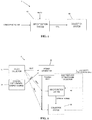
- FIG. 1 is a generalized block diagram of a system, generally designated by reference number 1, for removing carbon dioxide from an atmosphere according to an exemplary embodiment of the present invention.
- the system 1 includes an air extraction system 40 and a collection system 50, that isolates the removed carbon dioxide to a location for at least one of sequestration, storage and generation of a renewable carbon fuel or the generation of a non-fuel product such as fertilizer and construction materials.
- the air extraction system 40 preferably incorporates any known or later-discovered CO 2 extraction method, including methods which use a medium to absorb and/or bind CO 2 from the atmospheric air by exposing the medium to chemical, electrical and/or physical interaction with the CO 2 in the captured air.
- the medium may be liquid, gaseous or solid, or a combination of liquid, gaseous and solid substances, where in the case of solids, the substance is preferably porous.
- the medium is preferably recyclable so that after the CO 2 is captured by the medium and separated from the medium for sequestration, the medium can be reused for absorption/binding of additional CO 2 .
- the medium may be sequestered along with the captured CO 2 . As shown in FIG. 1 , the separation of the CO 2 from the medium, as well as other processes such as the absorption/binding of CO 2 and the sequestration of the CO 2 performed by the sequestration system 50, may be made more efficient by the addition of heat to the air extraction system 40.
- the heat is process heat generated e.g. by a solar energy generator, such as a solar collector, to be described in further detail below.
- process heat may be provided by other types of energy sources, such as, for example, fossil fuel, geothermal, nuclear, biomass, and other renewable energy sources.
- process heat refers to the lower temperature heat remaining after the higher temperature heat has been used to generate electricity. More generally, the term “process heat” refers to any low temperature heat remaining after a primary process or that is added by the process itself, such as, for example, exothermic carbonation reactions in which carbon dioxide is stored as a mineral or in fact when it binds to the medium and is captured.
- process heat may be provided from the use of sources of energy to produce products other than power or electrical generation.
- primary processing such as chemical processing, production of cement, steel or aluminum, production of energy products like coal to liquid energy products, refining, may use heat to drive the primary processing, and the unused heat remaining after the primary processing or created during the primary processing would be the process heat of such processing, and can be used in a system or method according to the principles of the present invention.
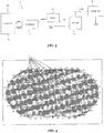
- FIG. 2 is a block diagram of a system, generally designated by reference number 2, for removing carbon dioxide from an atmosphere according to an exemplary embodiment of the present invention.
- the system 2 includes a solar collector 10, an optional supplemental energy source 20, a power generator 30, an air extraction system 42 and a collection system 50. Each of these components of the system 1 are explained in detail below.
- the solar collector 10 may be any known or future-discovered solar energy collection system, which may include solar energy collection units, such as, for exmple, concentrated solar power parabolic mirrors, and concentrated solar power towers. As is known in the art, the solar collector 10 converts solar energy to thermal energy, which may be used to drive the power generator 30. Residual thermal energy (i.e., process heat) may be used to drive the air extraction system 42 and/or the collection system 50. For example, the process heat may be used to improve the efficiency of chemical and/or physical reactions used in the air extraction system 42 to absorb CO 2 from the air and/or to drive off the CO 2 from the medium. In addition, in other exemplary embodiments, as shown by the dashed arrows in FIG. 2 , direct heat from the solar collector 10 may be used to drive the air extraction system 42 and/or the collection system 50.
- the power generator 30 may be, for example, a thermal power generator that converts the thermal energy provided by the solar collector to electricity.
- the suns heat may be focused on a medium, such as molten salts, that is then used to generate high temperature, high pressure steam that drives a turbine to generate electricity.
- the generated electricity may then be used to power the other components of the system 2, in addition to providing power to the general population as part of a power grid.
- the thermal energy provided by the solar collector 10 may be supplemented by energy generated by the supplemental energy source 20.
- the supplemental energy source 20 may be a waste incineration plant, which provides additional thermal energy to drive the power generator 30.
- renewable energy source may be used in addition to solar energy, and preferably a renewable energy source that produces heat as a precursor to the generation of electricity.
- Other potential renewable energy sources to be used in addition to solar energy include, for example, nuclear, biomass, and geothermal energy sources.
- the power generator 30 may be any known or later discovered fossil fuel facility (plant) that relies on the burning of fossil fuels, such as, for example, coal, fuel oil, natural gas and oil shale, for the generation of electricity.
- the power generator may also be for a purpose other than generating electricity (for example the power generator could be for chemical processing, or various other purposes like producing aluminum).
- the thermal energy produced by the fossil fuel power plant 30 is used to produce electricity and the residual thermal energy (i.e., process heat) may be used to drive the air extraction system 42 and/or the sequestration system 50.
- the process heat from the fossil fuel power plant 30 may be used to improve the efficiency of chemical and/or physical reactions used in the air extraction system 42 to absorb CO 2 from the air and/or to drive off the CO 2 from the medium.
- the residual heat provided by the fossil fuel power plant 30 may be supplemented by energy generated by a supplemental energy source.
- the supplemental energy source may be a waste incineration plant or a renewable energy source, such as, for example, solar, nuclear, biomass, and geothermal energy sources, which provides additional thermal energy to drive the air extraction system 42 and/or the collection system 50.
- Process heat from the supplemental energy source may also be used to drive the air extraction system 42 and/or the collection system 50.
- process heat may be provided from the use of sources of energy to produce products other than power or electrical generation.
- primary processing such as chemical processing, production of cement, steel or aluminum, refining, production of energy products like coal and liquid energy products, may use heat to drive the primary processing, and the unused heat remaining after the primary processing or created during the primary processing would be the process heat of such processing, and can be used in a system or method according to the principles of the present invention.
- FIG. 3 is a block diagram of the air extractor system 42 useable with the system 2 according to an exemplary embodiment of the present invention.
- the air extractor system 42 includes an air contactor 41, a causticizer 43, a slaker 45, a calciner 47 and a capture unit 49.
- the air contactor 41 may use a sorbent material to selectively capture CO 2 from the air, and may be composed of any known or later-discovered contactor structures, such as, for example, large convection towers, open, stagnant pools, and packed scrubbing towers.
- the sorbent material may be sodium hydroxide (NaOH), which readily absorbs CO 2 from the air.
- capture methods such as, for example, chemical absorption, physical and chemical adsorption, low-temperature distillation, gas-separation membranes, mineralization/biomineralization and vegetation.
- aqueous amine solutions or amine enriched solid sorbents may be used to absorb CO 2 .
- the sorbent material is regenerated and the capture method requires less than about 100 - 120°C heat to regenerate the sorbent material.
- CO 2 may be absorbed into an NaOH solution forming sodium carbonate (Na 2 CO 3 ), e.g. in the manner described by Stolaroff et all in an article entitled "A pilot-scale prototype contactor for CO 2 capture from ambient air: cost and energy requirements", which article can be found at www.ucalgary.ca/ ⁇ keith/papers/84. Stolaroff .AirCaptureGHGT-8.p.pdf, and is incorporated herein by reference.
- other known or future-developed absorbers may also be used as an alternative or in addition to an NaOH solution.
- the generated Na 2 CO 3 is then sent to the causticizer 43, where the NaOH is regenerated by addition of lime (CaO) in a batch process.
- the resulting CaCO 3 solid is sent to the calciner 47 where it is heated in a kiln to regenerate the CaO, driving off the CO 2 in a process known as calcination.
- the regenerated CaO is then sent through the slaker 45, which produces slaked lime Ca(OH) 2 for use in the causticizer 43.
- the capture unit 49 captures the CO 2 driven off at the calciner 47 using any know or later-discovered CO 2 capturing method that is effective in the low concentrations in which CO 2 is present in the atmosphere and that needs only low temperature heat for regeneration.
- the capture unit 49 may use an amine based capture system, such as the system described in Gray et al U.S. Patent No. 6,547,854, dated April 15, 2003 , and also Sirwardane US patent number 6908497, dated June 21, 2005 , both of which are incorporated herein by reference.
- the capture unit 49 may also compress the captured CO 2 to liquid form so that the CO 2 may be more easily sequestered.
- the collection system 50 isolates the removed carbon dioxide to a location for at least one of sequestration, storage and generation of a renewable carbon fuel or the generation of a non-fuel product such as fertilizer and construction materials.
- the collection system 50 may use any known or future-discovered carbon, sequestration and/or storing techniques, such as, for example, injection into geologic formations or mineral sequestration.
- the captured CO 2 may be sequestered in geologic formations such as, for example, oil and gas reservoirs, unmineable coal seams and deep saline reservoirs.
- injection of CO 2 into a geologic formation may enhance the recovery of hydrocarbons, providing the value-added byproducts that can offset the cost of CO 2 capture and collection.
- CO 2 injection of CO 2 into an oil or natural gas reservoir pushes out the product in a process known as enhanced oil recovery.
- the captured CO 2 may be sequestered underground, and according to at least one embodiment of the invention at a remote site upwind from the other components of the system 2 so that any leakage from the site is re-captured by the system 2.
- CO 2 may be sequestered by a carbonation reaction with calcium and magnesium silicates, which occur naturally as mineral deposits.
- CO 2 may be reacted with forsterite and serpentine, which produces solid calcium and magnesium carbonates in an exothermic reaction.
- 1/2Mg 2 SiO 4 + CO 2 MgCO 3 + 1/2SiO 2 + 95kJ/mole
- 1/3Mg 3 Si 2 O 5 (OH) 4 + CO 2 MgCO 3 + 2/3SiO 2 + 2/3H 2 O + 64kJ/mole
- both the air capture and air sequestration processes described herein may use electricity and/or thermal energy generated by the solar collector 10 (or other renewable energy source) to drive the necessary reactions and power the appropriate system components.
- a high temperature carrier may be heated up to a temperature in a range of about 400°C to about 500°C to generate steam to run a generator for electricity, and the lower temperature steam that exits from the electrical generating turbines can be used to drive off the CO 2 and regenerate the sorbent (e.g., NaOH).
- the temperature of the high temperature heat, the generated electricity and the temperature of the lower temperature process heat remaining after electricity production can be adjusted to produce the mix of electricity production and CO 2 removal that is considered optimal for a given application.
- still lower temperature process heat that emerges out of the capture and sequestration steps may be used to cool equipment used in these steps.
- One or more systems for removing carbon dioxide from an atmosphere may be used as part of a global thermostat according to an exemplary embodiment of the present invention.
- the system described herein may be used to alter the global average temperature.
- several carbon dioxide capture and sequestration systems may be located at different locations across the globe so that operation of the multiple systems may be used to alter the CO 2 concentration in the atmosphere and thus change the greenhouse gas heating of the planet. Locations may be chosen so as to have the most effect on areas such as large industrial centers and highly populated cities, or natural point sources of CO 2 each of which could create locally higher concentrations of CO 2 that would enable more cost efficient capture.
- multiple systems 1 may be scattered across the globe, and international cooperation, including, for example, international funding and agreements, may be used to regulate the construction and control of the systems 1.
- greenhouse gases concentration can be changed to alter the average global temperature of the planet to avoid cooling and warming periods, which can be destructive to human and ecological systems.
- temperatures swings in the future could be a direct cause of massive damage and destabilization of human society from conflicts resulting from potential diminished resources.
- the global thermostat described herein may be the key to preventing such disasters in the decades to come.
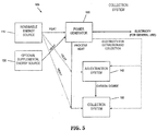
- FIG. 5 is a block diagram of a system, generally designated by reference number 100, for removing carbon dioxide from an atmosphere according to another exemplary embodiment of the present invention.
- the system 100 includes a renewable energy source 110, an optional supplemental energy source 120, a power generator 130, an air extraction system 142 and a collection system 150.
- the renewable energy source 110 may be any known or future-discovered energy source besides solar, such as, for example, nuclear, geothermal, and biomass energy sources.
- the renewal energy source produces thermal energy, which can be used to produce electricity and to improve the efficiency of the various chemical and/or physical reactions that take place within the air extraction system 142 and the collection system 150.
- the air extraction system 142 and the collection system 150 may be the same as described with reference to the previous embodiment, or may include components according to any other known or future-discovered air extraction and collection systems.
- a plurality of systems 100 may be strategically placed across the globe, and control of the systems 100 may be coordinated so as to collectively function as a global thermostat.
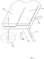
- FIGS 6-9 are schematic illustrations of several ways that carbon dioxide can be removed from an atmosphere, according to the principles of the present invention.
- a pair of substrate 600, 602 are illustrated, each of which has a medium (e.g. NAOH, an amine) that can be brought into contact with an atmosphere to remove carbon dioxide from the atmosphere.
- the substrates 600, 602 are pancake shaped (in the sense that they are relatively large area compared to their thickness) oriented vertically, and can each be relatively large (in surface area) and relatively thin (e.g. on the order of a few millimeters, and preferably not thicker than a meter).
- Each substrate can move (e.g.
- the substrates 600, 602 are porous with large surface areas, so that air directed at a substrate can flow through the substrate.
- carbon dioxide laden air is directed at the substrate (e.g. by a fan 604 shown in dashed lines), so that as the air flows through the substrate, the carbon dioxide contacts the medium and is substantially removed from the air.
- carbon dioxide laden air is directed at and through the substrate so that carbon dioxide comes into contact with the medium, carbon dioxide is substantially removed from the air by the medium, and air from which the carbon dioxide has been substantially removed is directed away from the substrate.
- process heat is directed at the substrate (e.g. via a fluid conduit 606), and carbon dioxide is removed (drawn off) by a source of fluid that is directed at the substrate (in the direction shown by arrow 608) and a source of suction 610 by which carbon dioxide that has been removed from the medium is drawn away from the substrate.
- the substrates 600, 602 can alternatively move between the upper and lower positions, so that the substrate in the upper position is removing carbon dioxide from the air and carbon dioxide is being removed from the substrate in the lower position. It should be noted that rather than the fan, if there are strong winds available natural wind flows can be used to drive the air through the substrate. In addition, as described below, the fan can be replaced with a solar driven source (or by either wind or thermally-driven air currents), in which case the efficiency and cost reduction of extraction of carbon dioxide from atmospheric air can be further improved.
- the means for generating the air flows, the flow of process heat, and the flow of carbon dioxide away from the substrate can be switched as carbon dioxide is captured from the air and then extracted from the medium, as will be readily apparent to those in the art.
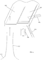
- FIG 7 is a schematic illustration of another version of a medium for removing carbon dioxide from an atmosphere and for removing carbon dioxide from the medium, according to the principles of the present invention.
- a pair of substrates 700, 702 are illustrated, each of which has a medium (e.g. NAOH, an amine) that can be brought into contact with an atmosphere to remove carbon dioxide from the atmosphere.
- the substrates 700, 702 are oriented horizontally, and can each be relatively large (in surface area) and relatively thin (e.g. on the order of millimeters or centimeters). Each substrate can move horizontally (e.g.
- the substrates 700, 702 are porous, so that air directed at a substrate can flow through the substrate.
- an air extraction position e.g. the position of substrate 700
- carbon dioxide laden air is directed at the substrate (e.g. by a fan 704 shown in dashed lines), so that as the air flows through the substrate, the carbon dioxide contacts the medium and is substantially removed from the air.
- carbon dioxide laden air is directed at and through the substrate so that carbon dioxide comes into contact with the medium, carbon dioxide is substantially removed from the air by the medium, and air from which the carbon dioxide has been substantially removed is directed away from the substrate.
- process heat is directed at the substrate (e.g. via a fluid conduit 706), and carbon dioxide is removed (drawn off) by a source of fluid that is directed at the substrate (in the direction shown by arrow 708) and a source of suction 710 by which carbon dioxide that has been removed from the medium is drawn away from the substrate.
- the substrates 700, 702 can alternatively move between the air extraction and carbon extraction positions, so that the substrate in the air extraction position is removing carbon dioxide from the air and carbon dioxide is being removed from the substrate in the carbon extraction position It should be noted that rather than the fan, if there are strong winds available natural wind flows can be used to drive the air through the substrate. In addition, as described below, the fan can be replaced with a solar driven source (or by either wind or thermally-driven air currents), in which case the efficiency and cost reduction of extraction of carbon dioxide from atmospheric air can be further improved.
- the means for generating the air flows, the flow of process heat, and the flow of carbon dioxide away from the substrate can be switched as carbon dioxide is captured from the air and then extracted from the medium, as will be readily apparent to those in the art.
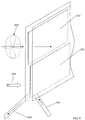
- the version of the invention shown in FIG. 9 is generally similar to the horizontally oriented version of FIG. 7 , but in the version of FIG. 9 , rather than a fan being the source that moves the carbon laden air through the substrate in the air extraction position (e.g. substrate 900), there is a source of gas flow that is generated from a solar heating tower or chimney (shown schematically at 912 in FIG. 9 ).
- a solar chimney can be generated by heating an air mass with the sun.
- the solar chimney would have a "skirt" (shown in dashed lines 913 in FIG. 9 ) that enables the solar heated air to be concentrated in the chimney.
- a solar field with a solar chimney can be associated with a system and structure that removes carbon dioxide from the atmosphere and removes carbon dioxide from a medium in the manner shown and described in connection with FIG. 7 .
- the carbon dioxide laden air is heated by solar energy and that air is allowed to rise in the solar funnel or tower 912. Because of the tendency for the hot air to rise, an upward draft is generated, that would carry with it carbon dioxide laden air, and the substrate 900 would be positioned in the way of that upward draft.
- the carbon dioxide laden air would be directed through the substrate 900 in the air extraction position, and carbon dioxide would be removed from the substrate 902 in the carbon extraction position in the same way as shown and described in connection with FIG. 7 .
- the costs of extraction are further reduced, and the overall operation is highly renewable.
- provision would need to be made for those periods when the sun didn't shine, and some form of driver similar to the fan 704 ( FIG. 7 ) would be needed.
- the efficiency and cost reduction of extraction of carbon dioxide from atmospheric air can be further improved.
- FIG 8 is a schematic illustration of yet another version of a medium for removing carbon dioxide from an atmosphere and for removing carbon dioxide from the medium, according to the principles of the present invention.
- the medium from which carbon dioxide is removed from atmospheric air and from which carbon dioxide is removed from the medium is disposed on a continuously moving substrate 800.
- the substrate moves through an air extraction zone 814, where carbon dioxide laden air is directed at and through the substrate (which is also porous as with the prior embodiments) so that carbon dioxide is removed from the air.
- the substrate 800 then moves to a carbon extraction zone 816, where process heat is directed at the substrate and carbon is drawn away from the substrate in the manner described above in connection with FIGS. 6 , 7 .
- the substrate 800 moves to and through a heat exchange zone 818 where the temperature of the substrate is lowered (e.g. by the air that flowed through the substrate in the air extraction zone, and by any additional cooling device that may be useful in reducing the temperature of the substrate to a level that enables it to efficiently remove carbon dioxide from the air when the substrate moves back through the extraction zone 814.
- the system of FIG. 8 may have another carbon extraction zone 816, where process heat is directed at the substrate and carbon is drawn away from the substrate in the manner described above in connection with FIGS. 6 , 7 .
- the removal of carbon dioxide from the air can be at least partially performed under non equilibrium conditions.
- applicants' preferred concept for extracting carbon dioxide from the atmosphere comprises using a relatively thin, large surface area substrate with a medium (e.g. an amine) that removes carbon dioxide from the atmosphere and using process heat to remove carbon dioxide from the medium.
- a medium e.g. an amine
- process heat to remove carbon dioxide from the medium.
- Also disclosed herein is a system for removing carbon dioxide from an atmosphere to reduce global warming which can increase availability of renewable energy or non-fuel products such as fertilizers and construction materials, comprising: an air extraction system that collects carbon dioxide from the atmosphere through a medium and removes carbon dioxide from the medium; a collection system that isolates the removed carbon dioxide to a location for at least one of sequestration, storage and generation of a renewable carbon fuel or non-fuel products such as fertilizers and construction materials; and one or more energy sources that supply process heat to the air extraction system to remove the carbon dioxide from the medium and which can regenerate it for continued use.
- the one or more energy sources may be selected from the group of primary energy sources consisting of: fossil fuel, geothermal, nuclear, solar, biomass and other renewable energy sources and exothermic chemical processes whose use can result in a supply of process heat.
- the air extraction system may comprise an air contactor that includes the medium to absorb carbon dioxide from the atmosphere.
- the air contactor may be selected from the group of air contactors consisting of: convection towers, absorption pools, packed scrubbing towers, and separation systems in which the medium is carried by a pancake shaped substrate.
- the medium may be selected from the group of mediums consisting of: a liquid, a porous solid, a gas and mixtures thereof.
- the medium may be an NaOH solution.
- the medium may comprise an amine attached to the surface of a substrate.
- the air extraction system may collect carbon dioxide and the sequestration system may isolate the removed carbon dioxide using the process heat supplied by the one or more energy sources.
- the location may be underground.
- the location may be at a remote site upwind from one or more other components of the system.
- Also disclosed herein is a method for removing carbon dioxide from an atmosphere to reduce global warming and increase availability of renewable energy, comprising: collecting air from the atmosphere; removing carbon dioxide from the collected air; isolating the removed carbon dioxide for at least one of sequestration, storage and generation of a renewable carbon fuel or non-fuel products such as fertilizers and construction materials , wherein at least one of the collecting, removing and isolating steps is performed using an energy source that comprises process heat.
- the step of removing may comprise absorbing the carbon dioxide using an absorber.
- the absorber may be an NaOH solution.
- the absorber may comprise an amine.
- the step of isolating may comprise at least one of mineral sequestration and injection into geologic formations.
- Also disclosed herein is a system for producing a negative carbon dioxide effect on a planet's atmosphere, comprising: a system that provides a medium for extracting carbon dioxide from the atmosphere and uses process heat for extracting carbon dioxide from the medium and to regenerate it so it can be reused.
- the process heat may be obtained from a primary energy source selected from the group of energy sources consisting of: fossil fuel, geothermal, nuclear, solar, biomass and other renewable energy sources and exothermic chemical processes whose use can result in a supply of process heat.
- the system may include a collection system that isolates the removed carbon dioxide to a location for at least one of sequestration, storage and generation of a renewable carbon fuel or a non-fuel product such as fertilizer and construction materials.
- the air extraction system may comprise an air contactor that includes the medium that extracts carbon dioxide from the atmosphere.
- the air contactor may be selected from the group of air contactors consisting of:
- the medium may be selected from the group of mediums consisting of: a liquid, a porous solid, a gas and mixtures thereof.
- the medium may be an NaOH solution.
- the medium may comprise an amine.
- the air extraction system may collect carbon dioxide and the collection system may isolate the removed carbon dioxide using the heat supplied by the energy source.
- the location may be underground.
- the location may be at a remote site upwind from one or more other components of the system.
- a medium for extracting carbon dioxide from the air may be provided on a porous relatively large area pancake shaped substrate.
- the step of removing carbon dioxide from the air may comprise directing the air at the substrate, and removing carbon dioxide from the medium by directing process heat at the substrate and providing a flow of carbon dioxide away from the substrate.
- the substrate may be in a substantially vertical orientation during the steps of removing carbon dioxide from the air and removing carbon dioxide from the medium.
- the substrate may be in a substantially horizontal orientation during the steps of removing carbon dioxide from the air and removing carbon dioxide from the medium.
- the substrate may be moveable in a substantially continuous path during the steps of removing carbon dioxide from the air and removing carbon dioxide from the medium.
- Removing carbon dioxide from the air may be at least partially performed under non equilibrium conditions.
- Removing carbon dioxide from the air may include the step of using fluid from a solar heating tower as an energy source for directing the air at a medium that is used to remove carbon dioxide from the air.
- a global thermostat for controlling average temperature of a planet's atmosphere, comprising a plurality of systems, each of which is capable of producing a negative carbon dioxide effect on a planet's atmosphere by extracting carbon dioxide from the atmosphere and uses process heat for extracting carbon dioxide from the medium, so that the plurality of systems together can effectively extract carbon dioxide from the atmosphere at a rate that is faster than the rate at which the carbon dioxide is increasing in the atmosphere.
Applications Claiming Priority (4)
| Application Number | Priority Date | Filing Date | Title |
|---|---|---|---|
| US11/805,271 US20080289499A1 (en) | 2007-05-21 | 2007-05-21 | System and method for removing carbon dioxide from an atmosphere and global thermostat using the same |
| US11/805,477 US20080289500A1 (en) | 2007-05-22 | 2007-05-22 | System and method for removing carbon dioxide from an atmosphere and global thermostat using the same |
| US11/825,468 US20080289319A1 (en) | 2007-05-22 | 2007-07-06 | System and method for removing carbon dioxide from an atmosphere and global thermostat using the same |
| EP08756015.7A EP2160234B1 (de) | 2007-05-21 | 2008-05-21 | Entfernung von kohlendioxid aus einer atmosphàre und globaler thermostat |
Related Parent Applications (1)
| Application Number | Title | Priority Date | Filing Date |
|---|---|---|---|
| EP08756015.7A Division EP2160234B1 (de) | 2007-05-21 | 2008-05-21 | Entfernung von kohlendioxid aus einer atmosphàre und globaler thermostat |
Publications (1)
| Publication Number | Publication Date |
|---|---|
| EP3269443A1 true EP3269443A1 (de) | 2018-01-17 |
Family
ID=40122206
Family Applications (2)
| Application Number | Title | Priority Date | Filing Date |
|---|---|---|---|
| EP17162034.7A Withdrawn EP3269443A1 (de) | 2007-05-21 | 2008-05-21 | Entfernung von kohlendioxid aus einer atmosphäre und globaler thermostat |
| EP08756015.7A Active EP2160234B1 (de) | 2007-05-21 | 2008-05-21 | Entfernung von kohlendioxid aus einer atmosphàre und globaler thermostat |
Family Applications After (1)
| Application Number | Title | Priority Date | Filing Date |
|---|---|---|---|
| EP08756015.7A Active EP2160234B1 (de) | 2007-05-21 | 2008-05-21 | Entfernung von kohlendioxid aus einer atmosphàre und globaler thermostat |
Country Status (15)
| Country | Link |
|---|---|
| EP (2) | EP3269443A1 (de) |
| JP (1) | JP5462786B2 (de) |
| KR (1) | KR101612748B1 (de) |
| CN (2) | CN101711180A (de) |
| AR (1) | AR066665A1 (de) |
| BR (1) | BRPI0811622B1 (de) |
| CA (1) | CA2688856C (de) |
| DK (1) | DK2160234T3 (de) |
| ES (1) | ES2629091T3 (de) |
| HU (1) | HUE034859T2 (de) |
| MX (1) | MX344333B (de) |
| PL (1) | PL2160234T3 (de) |
| SM (1) | SMP200900097B (de) |
| TW (1) | TWI441671B (de) |
| WO (1) | WO2008144708A1 (de) |
Families Citing this family (18)
| Publication number | Priority date | Publication date | Assignee | Title |
|---|---|---|---|---|
| US20080289495A1 (en) | 2007-05-21 | 2008-11-27 | Peter Eisenberger | System and Method for Removing Carbon Dioxide From an Atmosphere and Global Thermostat Using the Same |
| US8163066B2 (en) * | 2007-05-21 | 2012-04-24 | Peter Eisenberger | Carbon dioxide capture/regeneration structures and techniques |
| US20140130670A1 (en) | 2012-11-14 | 2014-05-15 | Peter Eisenberger | System and method for removing carbon dioxide from an atmosphere and global thermostat using the same |
| WO2010059268A1 (en) | 2008-11-19 | 2010-05-27 | Murray Kenneth D | Carbon dioxide control device to capture carbon dioxide from vehicle combustion waste |
| US20110248498A1 (en) * | 2009-07-20 | 2011-10-13 | Slobodan Tepic | Generating electrical power utilizing surface-level hot air as the heat source, high atmosphere as the heat sink and a microwave beam to initiate and control air updraft |
| PL2563495T3 (pl) | 2010-04-30 | 2020-05-18 | Peter Eisenberger | Metoda wychwytywania ditlenku węgla |
| US9028592B2 (en) | 2010-04-30 | 2015-05-12 | Peter Eisenberger | System and method for carbon dioxide capture and sequestration from relatively high concentration CO2 mixtures |
| US20130095999A1 (en) | 2011-10-13 | 2013-04-18 | Georgia Tech Research Corporation | Methods of making the supported polyamines and structures including supported polyamines |
| US11059024B2 (en) | 2012-10-25 | 2021-07-13 | Georgia Tech Research Corporation | Supported poly(allyl)amine and derivatives for CO2 capture from flue gas or ultra-dilute gas streams such as ambient air or admixtures thereof |
| EP3071315A4 (de) * | 2013-11-21 | 2017-08-30 | Muffett, Ruth | Absorption von atmosphärischem kohlenstoffdioxid |
| BR112016015436B8 (pt) | 2013-12-31 | 2022-08-30 | Graciela Chichilnisky | Sistema de movimento rotativo de leitos multimonolíticos para a remoção de co2 da atmosfera |
| US9491911B2 (en) | 2014-02-19 | 2016-11-15 | Dennis Jason Stelmack | Method for modifying environmental conditions with ring comprised of magnetic material |
| WO2016004963A2 (en) * | 2014-07-08 | 2016-01-14 | Mahran Asmaa Mohamed Mahmoud | Generate electricity from green house gases, depending on their ability to absorb thermal energy (uv rays) emitted by the sun and its heat emission |
| WO2020149744A1 (en) * | 2019-01-14 | 2020-07-23 | Engsl Minerals Dmcc | Carbon capture and storage |
| JP7397085B2 (ja) | 2019-01-23 | 2023-12-12 | ブルー プラネット システムズ コーポレーション | 炭酸塩骨材組成物ならびにその製造および使用方法 |
| KR102482021B1 (ko) | 2021-01-12 | 2022-12-26 | 고려대학교 산학협력단 | 이산화탄소로 유도되는 고밀도 열에너지 발생 가능한 이산화탄소 흡수제 |
| WO2023066924A1 (en) | 2021-10-21 | 2023-04-27 | Shell Internationale Research Maatschappij B.V. | Systems and processes for maintaining continuous carbon dioxide capture |
| CA3234473A1 (en) | 2021-10-21 | 2023-04-27 | Shell Internationale Research Maatschappij B.V. | Systems and processes for maintaining continuous carbon dioxide capture utilising waste excess energy from parallel and downstream processes |
Citations (12)
| Publication number | Priority date | Publication date | Assignee | Title |
|---|---|---|---|---|
| US3491031A (en) * | 1966-11-18 | 1970-01-20 | Calgon C0Rp | Reactivation of monoethanolamine impregnated activated carbon |
| US4197421A (en) * | 1978-08-17 | 1980-04-08 | The United States Of America As Represented By The United States Department Of Energy | Synthetic carbonaceous fuels and feedstocks |
| US4455153A (en) * | 1978-05-05 | 1984-06-19 | Jakahi Douglas Y | Apparatus for storing solar energy in synthetic fuels |
| WO1998017388A1 (en) * | 1996-10-22 | 1998-04-30 | United Technologies Corporation | Regenerable solid amine sorbent |
| US6387337B1 (en) * | 2000-07-14 | 2002-05-14 | The United States Of America As Represented By The United States Department Of Energy | Carbon dioxide capture process with regenerable sorbents |
| US6547854B1 (en) | 2001-09-25 | 2003-04-15 | The United States Of America As Represented By The United States Department Of Energy | Amine enriched solid sorbents for carbon dioxide capture |
| US20040213705A1 (en) * | 2003-04-23 | 2004-10-28 | Blencoe James G. | Carbonation of metal silicates for long-term CO2 sequestration |
| US6908497B1 (en) | 2003-04-23 | 2005-06-21 | The United States Of America As Represented By The Department Of Energy | Solid sorbents for removal of carbon dioxide from gas streams at low temperatures |
| US20050180910A1 (en) * | 2003-12-31 | 2005-08-18 | Ah-Hyung Park | Carbon dioxide sequestration using alkaline earth metal-bearing minerals |
| WO2005108297A2 (en) * | 2004-05-04 | 2005-11-17 | The Trustees Of Columbia University In The City Of New York | Carbon dioxide capture and mitigation of carbon dioxide emissions |
| WO2006036396A2 (en) * | 2004-08-20 | 2006-04-06 | Global Research Technologies, Llc | Removal of carbon dioxide from air |
| WO2007016271A2 (en) * | 2005-07-28 | 2007-02-08 | Global Research Technologies, Llc | Removal of carbon dioxide from air |
Family Cites Families (12)
| Publication number | Priority date | Publication date | Assignee | Title |
|---|---|---|---|---|
| DE1189094B (de) * | 1962-06-09 | 1965-03-18 | Linde Eismasch Ag | Verfahren zum Entfernen von Kohlendioxyd aus Gasgemischen |
| JPS5462641A (en) * | 1977-10-11 | 1979-05-19 | Robertshaw Controls Co | Thermostat |
| JPH03245811A (ja) * | 1990-02-21 | 1991-11-01 | Sumitomo Heavy Ind Ltd | 大気中の炭酸ガスの除去・濃縮固定方法 |
| JP3208184B2 (ja) * | 1992-08-21 | 2001-09-10 | 三洋電機株式会社 | 苗育成貯蔵庫 |
| JPH0751537A (ja) * | 1993-06-30 | 1995-02-28 | Mitsubishi Heavy Ind Ltd | Co2 含有ガス中のco2 を除去する方法 |
| US5595238A (en) * | 1994-09-16 | 1997-01-21 | Engelhard/Icc | Rotatably supported regenerative fluid treatment wheel assemblies |
| JP2001300250A (ja) * | 2000-04-27 | 2001-10-30 | Ishikawajima Harima Heavy Ind Co Ltd | 二酸化炭素濃縮装置 |
| JP2003326155A (ja) * | 2002-05-09 | 2003-11-18 | Kaken:Kk | 大気中の二酸化炭素の削減方法とその装置 |
| US20060051274A1 (en) * | 2004-08-23 | 2006-03-09 | Wright Allen B | Removal of carbon dioxide from air |
| JP2006075717A (ja) * | 2004-09-09 | 2006-03-23 | Nippon Steel Corp | 炭酸ガスの利用方法 |
| CN1772341A (zh) * | 2004-11-11 | 2006-05-17 | 中国科学院工程热物理研究所 | 一种去除挥发性有机物的方法和装置 |
| CN1709553A (zh) * | 2005-06-02 | 2005-12-21 | 中国科学院过程工程研究所 | 氨基酸类离子液体用于酸性气体吸收 |
-
2008
- 2008-05-21 DK DK08756015.7T patent/DK2160234T3/en active
- 2008-05-21 CN CN200880016864A patent/CN101711180A/zh active Pending
- 2008-05-21 ES ES08756015.7T patent/ES2629091T3/es active Active
- 2008-05-21 KR KR1020097026486A patent/KR101612748B1/ko active IP Right Grant
- 2008-05-21 JP JP2010509510A patent/JP5462786B2/ja active Active
- 2008-05-21 CA CA2688856A patent/CA2688856C/en active Active
- 2008-05-21 AR ARP080102156A patent/AR066665A1/es active IP Right Grant
- 2008-05-21 TW TW097118695A patent/TWI441671B/zh active
- 2008-05-21 CN CN201610824580.5A patent/CN106268183A/zh active Pending
- 2008-05-21 EP EP17162034.7A patent/EP3269443A1/de not_active Withdrawn
- 2008-05-21 HU HUE08756015A patent/HUE034859T2/en unknown
- 2008-05-21 BR BRPI0811622-9A patent/BRPI0811622B1/pt active IP Right Grant
- 2008-05-21 EP EP08756015.7A patent/EP2160234B1/de active Active
- 2008-05-21 WO PCT/US2008/064311 patent/WO2008144708A1/en active Application Filing
- 2008-05-21 MX MX2009012631A patent/MX344333B/es active IP Right Grant
- 2008-05-21 PL PL08756015T patent/PL2160234T3/pl unknown
-
2009
- 2009-12-17 SM SM200900097T patent/SMP200900097B/it unknown
Patent Citations (12)
| Publication number | Priority date | Publication date | Assignee | Title |
|---|---|---|---|---|
| US3491031A (en) * | 1966-11-18 | 1970-01-20 | Calgon C0Rp | Reactivation of monoethanolamine impregnated activated carbon |
| US4455153A (en) * | 1978-05-05 | 1984-06-19 | Jakahi Douglas Y | Apparatus for storing solar energy in synthetic fuels |
| US4197421A (en) * | 1978-08-17 | 1980-04-08 | The United States Of America As Represented By The United States Department Of Energy | Synthetic carbonaceous fuels and feedstocks |
| WO1998017388A1 (en) * | 1996-10-22 | 1998-04-30 | United Technologies Corporation | Regenerable solid amine sorbent |
| US6387337B1 (en) * | 2000-07-14 | 2002-05-14 | The United States Of America As Represented By The United States Department Of Energy | Carbon dioxide capture process with regenerable sorbents |
| US6547854B1 (en) | 2001-09-25 | 2003-04-15 | The United States Of America As Represented By The United States Department Of Energy | Amine enriched solid sorbents for carbon dioxide capture |
| US20040213705A1 (en) * | 2003-04-23 | 2004-10-28 | Blencoe James G. | Carbonation of metal silicates for long-term CO2 sequestration |
| US6908497B1 (en) | 2003-04-23 | 2005-06-21 | The United States Of America As Represented By The Department Of Energy | Solid sorbents for removal of carbon dioxide from gas streams at low temperatures |
| US20050180910A1 (en) * | 2003-12-31 | 2005-08-18 | Ah-Hyung Park | Carbon dioxide sequestration using alkaline earth metal-bearing minerals |
| WO2005108297A2 (en) * | 2004-05-04 | 2005-11-17 | The Trustees Of Columbia University In The City Of New York | Carbon dioxide capture and mitigation of carbon dioxide emissions |
| WO2006036396A2 (en) * | 2004-08-20 | 2006-04-06 | Global Research Technologies, Llc | Removal of carbon dioxide from air |
| WO2007016271A2 (en) * | 2005-07-28 | 2007-02-08 | Global Research Technologies, Llc | Removal of carbon dioxide from air |
Non-Patent Citations (1)
| Title |
|---|
| STOLAROFF ET AL.,: "A pilot-scale prototype contactor for C02 capture from ambient air: cost and energy requirements", Retrieved from the Internet <URL:www.ucalgary.ca/-keith/papers/84.Stolaroff.AirCaptureGHGT-8.p.pdf> |
Also Published As
| Publication number | Publication date |
|---|---|
| HUE034859T2 (en) | 2018-03-28 |
| CA2688856C (en) | 2016-10-18 |
| BRPI0811622A2 (pt) | 2014-11-11 |
| JP2010527771A (ja) | 2010-08-19 |
| SMAP200900097A (it) | 2010-01-19 |
| MX344333B (es) | 2016-12-13 |
| BRPI0811622B1 (pt) | 2020-09-15 |
| KR20100017867A (ko) | 2010-02-16 |
| DK2160234T3 (en) | 2017-07-17 |
| KR101612748B1 (ko) | 2016-04-15 |
| MX2009012631A (es) | 2010-04-27 |
| CA2688856A1 (en) | 2008-11-27 |
| CN101711180A (zh) | 2010-05-19 |
| EP2160234B1 (de) | 2017-03-22 |
| EP2160234A1 (de) | 2010-03-10 |
| CN106268183A (zh) | 2017-01-04 |
| JP5462786B2 (ja) | 2014-04-02 |
| SMP200900097B (it) | 2011-01-19 |
| TW200904512A (en) | 2009-02-01 |
| TWI441671B (zh) | 2014-06-21 |
| AR066665A1 (es) | 2009-09-02 |
| WO2008144708A1 (en) | 2008-11-27 |
| PL2160234T3 (pl) | 2017-10-31 |
| EP2160234A4 (de) | 2011-04-06 |
| ES2629091T3 (es) | 2017-08-07 |
Similar Documents
| Publication | Publication Date | Title |
|---|---|---|
| US9555365B2 (en) | System and method for removing carbon dioxide from an atmosphere and global thermostat using the same | |
| EP2160234B1 (de) | Entfernung von kohlendioxid aus einer atmosphàre und globaler thermostat | |
| US8500858B2 (en) | Carbon dioxide capture/regeneration method using vertical elevator | |
| US8500861B2 (en) | Carbon dioxide capture/regeneration method using co-generation | |
| US20100254883A1 (en) | System and method for removing carbon dioxide from an atmosphere and global thermostat using the same | |
| US20120000364A1 (en) | System and Method for Removing Carbon Dioxide from an Atmosphere and Global Thermostat Using the Same | |
| US20110000371A1 (en) | System and method for removing carbon dioxide from an atmosphere and global thermostat using the same | |
| US9908080B2 (en) | System and method for removing carbon dioxide from an atmosphere and global thermostat using the same |
Legal Events
| Date | Code | Title | Description |
|---|---|---|---|
| PUAI | Public reference made under article 153(3) epc to a published international application that has entered the european phase |
Free format text: ORIGINAL CODE: 0009012 |
|
| STAA | Information on the status of an ep patent application or granted ep patent |
Free format text: STATUS: THE APPLICATION HAS BEEN PUBLISHED |
|
| AC | Divisional application: reference to earlier application |
Ref document number: 2160234 Country of ref document: EP Kind code of ref document: P |
|
| AK | Designated contracting states |
Kind code of ref document: A1 Designated state(s): AT BE BG CH CY CZ DE DK EE ES FI FR GB GR HR HU IE IS IT LI LT LU LV MC MT NL NO PL PT RO SE SI SK TR |
|
| AX | Request for extension of the european patent |
Extension state: AL BA MK RS |
|
| STAA | Information on the status of an ep patent application or granted ep patent |
Free format text: STATUS: REQUEST FOR EXAMINATION WAS MADE |
|
| 17P | Request for examination filed |
Effective date: 20180716 |
|
| RBV | Designated contracting states (corrected) |
Designated state(s): AT BE BG CH CY CZ DE DK EE ES FI FR GB GR HR HU IE IS IT LI LT LU LV MC MT NL NO PL PT RO SE SI SK TR |
|
| STAA | Information on the status of an ep patent application or granted ep patent |
Free format text: STATUS: EXAMINATION IS IN PROGRESS |
|
| STAA | Information on the status of an ep patent application or granted ep patent |
Free format text: STATUS: EXAMINATION IS IN PROGRESS |
|
| 17Q | First examination report despatched |
Effective date: 20201012 |
|
| STAA | Information on the status of an ep patent application or granted ep patent |
Free format text: STATUS: EXAMINATION IS IN PROGRESS |
|
| GRAP | Despatch of communication of intention to grant a patent |
Free format text: ORIGINAL CODE: EPIDOSNIGR1 |
|
| STAA | Information on the status of an ep patent application or granted ep patent |
Free format text: STATUS: GRANT OF PATENT IS INTENDED |
|
| RIC1 | Information provided on ipc code assigned before grant |
Ipc: B01D 53/14 20060101ALI20220315BHEP Ipc: B01D 53/62 20060101AFI20220315BHEP |
|
| INTG | Intention to grant announced |
Effective date: 20220406 |
|
| STAA | Information on the status of an ep patent application or granted ep patent |
Free format text: STATUS: THE APPLICATION IS DEEMED TO BE WITHDRAWN |
|
| 18D | Application deemed to be withdrawn |
Effective date: 20220817 |