EP3269233B1 - Automatic feeder with feeding pipe - Google Patents
Automatic feeder with feeding pipe Download PDFInfo
- Publication number
- EP3269233B1 EP3269233B1 EP16760998.1A EP16760998A EP3269233B1 EP 3269233 B1 EP3269233 B1 EP 3269233B1 EP 16760998 A EP16760998 A EP 16760998A EP 3269233 B1 EP3269233 B1 EP 3269233B1
- Authority
- EP
- European Patent Office
- Prior art keywords
- feeding pipe
- motor
- connecting lever
- water supply
- supply pipeline
- Prior art date
- Legal status (The legal status is an assumption and is not a legal conclusion. Google has not performed a legal analysis and makes no representation as to the accuracy of the status listed.)
- Active
Links
- XLYOFNOQVPJJNP-UHFFFAOYSA-N water Substances O XLYOFNOQVPJJNP-UHFFFAOYSA-N 0.000 claims description 94
- 230000035929 gnawing Effects 0.000 claims description 43
- 239000000463 material Substances 0.000 claims description 38
- 238000007599 discharging Methods 0.000 claims description 21
- 238000003756 stirring Methods 0.000 claims description 7
- 230000001960 triggered effect Effects 0.000 description 14
- 238000009395 breeding Methods 0.000 description 6
- 230000001488 breeding effect Effects 0.000 description 6
- 238000010586 diagram Methods 0.000 description 4
- 239000012530 fluid Substances 0.000 description 4
- 230000036541 health Effects 0.000 description 4
- 241001465754 Metazoa Species 0.000 description 3
- 230000006872 improvement Effects 0.000 description 3
- 206010012735 Diarrhoea Diseases 0.000 description 2
- 241000282887 Suidae Species 0.000 description 2
- 239000003651 drinking water Substances 0.000 description 2
- 235000020188 drinking water Nutrition 0.000 description 2
- 239000008267 milk Substances 0.000 description 2
- 210000004080 milk Anatomy 0.000 description 2
- 235000013336 milk Nutrition 0.000 description 2
- 239000002699 waste material Substances 0.000 description 2
- 241000894006 Bacteria Species 0.000 description 1
- 208000018522 Gastrointestinal disease Diseases 0.000 description 1
- 230000009471 action Effects 0.000 description 1
- 230000009286 beneficial effect Effects 0.000 description 1
- 238000004891 communication Methods 0.000 description 1
- 230000007423 decrease Effects 0.000 description 1
- 230000006866 deterioration Effects 0.000 description 1
- 238000000855 fermentation Methods 0.000 description 1
- 230000004151 fermentation Effects 0.000 description 1
- 235000013305 food Nutrition 0.000 description 1
- 230000007774 longterm Effects 0.000 description 1
- 230000007246 mechanism Effects 0.000 description 1
- 238000000034 method Methods 0.000 description 1
- 238000012544 monitoring process Methods 0.000 description 1
- 239000000843 powder Substances 0.000 description 1
- 208000023504 respiratory system disease Diseases 0.000 description 1
- 230000004044 response Effects 0.000 description 1
- 210000003296 saliva Anatomy 0.000 description 1
- 230000008054 signal transmission Effects 0.000 description 1
- 230000004083 survival effect Effects 0.000 description 1
Images

Classifications
-
- A—HUMAN NECESSITIES
- A01—AGRICULTURE; FORESTRY; ANIMAL HUSBANDRY; HUNTING; TRAPPING; FISHING
- A01K—ANIMAL HUSBANDRY; AVICULTURE; APICULTURE; PISCICULTURE; FISHING; REARING OR BREEDING ANIMALS, NOT OTHERWISE PROVIDED FOR; NEW BREEDS OF ANIMALS
- A01K5/00—Feeding devices for stock or game ; Feeding wagons; Feeding stacks
- A01K5/02—Automatic devices
- A01K5/0225—Gravity replenishment from a reserve, e.g. a hopper
- A01K5/0241—Gravity replenishment from a reserve, e.g. a hopper dispensing by means of stirring mechanisms or agitators operated by the animal
-
- A—HUMAN NECESSITIES
- A01—AGRICULTURE; FORESTRY; ANIMAL HUSBANDRY; HUNTING; TRAPPING; FISHING
- A01K—ANIMAL HUSBANDRY; AVICULTURE; APICULTURE; PISCICULTURE; FISHING; REARING OR BREEDING ANIMALS, NOT OTHERWISE PROVIDED FOR; NEW BREEDS OF ANIMALS
- A01K5/00—Feeding devices for stock or game ; Feeding wagons; Feeding stacks
- A01K5/02—Automatic devices
-
- A—HUMAN NECESSITIES
- A01—AGRICULTURE; FORESTRY; ANIMAL HUSBANDRY; HUNTING; TRAPPING; FISHING
- A01K—ANIMAL HUSBANDRY; AVICULTURE; APICULTURE; PISCICULTURE; FISHING; REARING OR BREEDING ANIMALS, NOT OTHERWISE PROVIDED FOR; NEW BREEDS OF ANIMALS
- A01K5/00—Feeding devices for stock or game ; Feeding wagons; Feeding stacks
- A01K5/001—Fodder distributors with mixer or shredder
- A01K5/004—Fodder distributors with mixer or shredder with mixing or shredding element rotating on vertical axis
-
- A—HUMAN NECESSITIES
- A01—AGRICULTURE; FORESTRY; ANIMAL HUSBANDRY; HUNTING; TRAPPING; FISHING
- A01K—ANIMAL HUSBANDRY; AVICULTURE; APICULTURE; PISCICULTURE; FISHING; REARING OR BREEDING ANIMALS, NOT OTHERWISE PROVIDED FOR; NEW BREEDS OF ANIMALS
- A01K5/00—Feeding devices for stock or game ; Feeding wagons; Feeding stacks
- A01K5/02—Automatic devices
- A01K5/0216—Automatic devices for the distribution of liquid fodder
-
- A—HUMAN NECESSITIES
- A01—AGRICULTURE; FORESTRY; ANIMAL HUSBANDRY; HUNTING; TRAPPING; FISHING
- A01K—ANIMAL HUSBANDRY; AVICULTURE; APICULTURE; PISCICULTURE; FISHING; REARING OR BREEDING ANIMALS, NOT OTHERWISE PROVIDED FOR; NEW BREEDS OF ANIMALS
- A01K5/00—Feeding devices for stock or game ; Feeding wagons; Feeding stacks
- A01K5/02—Automatic devices
- A01K5/0258—Automatic devices with endless screws
-
- A—HUMAN NECESSITIES
- A01—AGRICULTURE; FORESTRY; ANIMAL HUSBANDRY; HUNTING; TRAPPING; FISHING
- A01K—ANIMAL HUSBANDRY; AVICULTURE; APICULTURE; PISCICULTURE; FISHING; REARING OR BREEDING ANIMALS, NOT OTHERWISE PROVIDED FOR; NEW BREEDS OF ANIMALS
- A01K7/00—Watering equipment for stock or game
- A01K7/02—Automatic devices ; Medication dispensers
- A01K7/06—Automatic devices ; Medication dispensers actuated by the animal
Definitions
- the present invention relates to an automatic feeder comprising a feeding pipe particularly to an automatic feeder for breeding sows and piglets comprising a feeding pipe.
- sow breeding quality will directly affect the survival rate and the growth quality of piglets.
- the requirements on feeds are as follows:
- EP0741965A1 describes a feeding equipment for pigs having a dry fodder storage container (2) from which emerges a feeder tube (3).
- a conveyor component (4) Inside the feeder tube is a conveyor component (4) and at the end of the tube is a mouthpiece (31) which can be secured with the mouth of the animal (9).
- a release unit (6) operated when the animal secures the mouthpiece to drive (5) the conveyor component.
- at least one fluid feed conduit (7) issues, through which controlled fluids can be introduced and mixed with the dry fodder.
- each fluid feed conduit is at least one valve (71) coupled with the release unit so that food and fluid are fed to the animal at the same time.
- US4508061A provides a feeding apparatus for dispensing dry granular feed directly into a hog's mouth.
- the apparatus comprises a supply conduit, an elongated feed tube, an auger positioned within said feed tube, and an electric motor or pawl and ratchet mechanism for rotating the auger.
- a lever is positioned near the outlet of the feed tube, the dimensions and spacing of the lever and feed tube outlet being such as to permit engulfment by the hog's mouth. When the roof of the hog's mouth depresses the lever, the auger is activated to deliver feed.
- the present invention designs an automatic feeder comprising a feeding pipe to solve the technical problems of the conventional feeder: it cannot ensure that the feed in the feeding tank is eaten by sows in time, that the feeder is launched when the sows want to eat, and that the health of the piglets will not be indirectly affected by excessive deteriorated feed in the feeding tank.
- an automatic feeder comprising a feeding pipe (1), a hopper (2), a spiral conveyor (3), a motor (4), a water supply pipeline (5) and a control unit (7); wherein a pressure sensor (14) is triggered and the feeding pipe (1) discharges a feed when a pig gnaws a gnawing block (12) on the feeding pipe (1) ; the hopper (2) is configured to be filled with a dry feed material; the spiral conveyor (3) has one end connected with the motor (4) and the other end located in the feeding pipe (1) and is configured to convey the dry feed material in the hopper (2) to the feeding pipe (1); the motor (4) provides power for rotation of the spiral conveyor (3); the water supply pipeline (5) provides water for mixing the dry feed material in the feeding pipe (1); and the control unit (7) powers on the motor (4) and opens the water supply pipeline (5) simultaneously after receiving a triggering signal from the pressure sensor (14), and powers off the motor (4) and closes the water supply pipeline (5)
- a mounting slot hole (16) for a triggering connecting lever is axially formed in the pipe wall of a discharging outlet (11) at the front end of the feeding pipe (1) and a mounting groove for gnawing block is radially formed in the pipe wall of the discharging outlet, the mounting slot hole (16) and the mounting groove are communicated with each other, a triggering connecting lever (13) has one end connected to the gnawing block (12) placed in the gnawing block mounting groove and the other end fixedly connected to the pressure sensor (14), and a gap is reserved between the triggering connecting lever (13) and the mounting slot hole (16); and when the gnawing block (12) is gnawed, the triggering connecting lever (13) is deformed to trigger the pressure sensor (14) to respond.
- the discharging outlet (11) at the front end of the feeding pipe (1) is connected with a conveying pipe (17) at the rear end of the feeding pipe (1), and the spiral conveyor (3) is arranged in the conveying pipe (17) at the rear end of the feeding pipe (1).
- discharging outlet (11) is connected with the conveying pipe (17) via a connecting joint (18), and the pressure sensor (14) is fixed onto the connecting joint (18).
- triggering connecting lever (13) is fixedly connected with the pressure sensor (14) via a connecting block (19).
- the present invention also provides an automatic feeder comprising a feeding pipe (1), a hopper (2), a spiral conveyor (3), a motor (4), a water supply pipeline (5) and a control unit (7), wherein a pressure sensor (14) or a switch is triggered and the feeding pipe (1) discharges a feed when a sow or a piglet gnaws a gnawing block (12) on the feeding pipe (1); the hopper (2) is configured to be filled with a dry feed material; the spiral conveyor (3) has one end connected with the motor (4) and the other end located in the feeding pipe (1) and is configured to convey the dry feed material in the hopper (2) to the feeding pipe (1); the motor (4) provides power for rotation of the spiral conveyor (3); the water supply pipeline (5) provides water for mixing the dry feed material in the feeding pipe (1) ; and the control unit (7) powers on the motor (4) and the water supply pipeline (5) simultaneously after receiving a triggering signal of the pressure sensor (14) or the switch.
- a pressure sensor (14) or a switch is triggered and the feeding pipe (1)
- the automatic feeder further comprises a triggering connecting lever (13), wherein a gap is reserved between a lower part of one end of the triggering connecting lever (13) and the feeding pipe (1), which end is fixedly connected with the gnawing block (12), a lever fulcrum is located on the feeding pipe (1), and the sensor or the switch is triggered along with upward movement of the other end of the triggering connecting lever (13).
- the automatic feeder further comprises a triggering connecting lever (13); a through hole is formed in the feeding pipe (1) in an axial direction; the triggering connecting lever (13) is inserted into the through hole; the triggering connecting lever (13) has one end fixed onto the wall of the feeding pipe (1); a middle part spaced from the feeding pipe (1) and connected with the gnawing block (12); and the other end for moving downwards to trigger the senor or the switch.
- the senor is the pressure sensor; and the switch is the travel switch.
- the end of the spiral conveyor (3), connected with the motor (4), is higher than the other end located in the feeding pipe (1) to prevent the water in the water supply pipeline (5) from flowing into the hopper (2).
- spiral conveyor (3) is connected with the motor (4) via a motor rod (41), and a stirring vane (42) for scattering the dry feed material is arranged on the motor rod (41).
- the water supply pipeline (5) is connected with a heater configured to heat water in the water supply pipeline (5).
- a water delivery pipeline (15) is connected between a water inlet of the water supply pipeline (5), which inlet enters the feeding pipe (1), and a water outlet of the feeding pipe (1), and is buried in the inner wall of the feeding pipe (1), and the water outlet of the feeding pipe (1) is located at the discharging outlet (11) of the feeding pipe (1).
- a feed receiving tank (6) is arranged below the feeding pipe (1).
- an automatic feeder comprising a feeding pipe (1), a hopper (2), a spiral conveyor (3), a motor (4), a water supply pipeline (5) and a control unit (7), wherein, the feeding pipe (1) discharges a feed when the sow or the piglet triggers infrared sensors through gnawing the feeding pipe (1); the hopper (2) is configured to be filled with a dry feed material; the spiral conveyor (3) has one end connected with the motor (4) and the other end placed in the feeding pipe (1), and is configured to convey the dry feed material in the hopper (2) to the feeding pipe (1); the motor (4) provides power for rotation of the spiral conveyor (3); the water supply pipeline (5) provides water mixing the dry feed material in the feeding pipe (1); the control unit (7) powers on the motor (4) and opens the water supply pipeline (5) simultaneously after receiving triggering signals of the infrared sensors; and the infrared sensors comprise a vertical infrared sensor (71) and a horizontal infrared sensor
- the automatic feeder of the present invention has the following beneficial effects.
- connection may be mechanical connection, electrical connection, communication of inner parts of two elements, direct connection, or indirect connection via an intermediation, and those skilled in the art can understand the specific meaning of the above terms in accordance with specific conditions.
- an automatic feeder comprises a feeding pipe 1, a hopper 2, a spiral conveyor 3, a motor 4, a water supply pipeline 5 and a control unit 7.
- a sensor or a switch is triggered to work and the feeding pipe 1 discharges a feed when a sow or a piglet gnaws a gnawing block 12 on the feeding pipe 1;
- the hopper 2 is configured to be filled with a dry feed material;
- the spiral conveyor 3 has one end connected with the motor 4 and the other end placed in the feeding pipe 1, and the spiral conveyor 3 is configured to convey the dry feed material in the hopper 2 to the feeding pipe 1;
- the motor 4 provides power for rotation of the spiral conveyor 3;
- the water supply pipeline 5 provides water for mixing the dry feed material in the feeding pipe 1; and the control unit 7 powers on the motor 4 and opens the water supply pipeline 5 simultaneously after receiving a triggering signal of a sensor or a switch.
- a first working principle of the gnawing block 12 is as below: a triggering connecting lever 13 is arranged, a gap is reserved between a lower part of one end of the triggering connecting lever 13 and the feeding pipe 1, the end is fixedly connected with the gnawing block 12, a lever fulcrum is located on the feeding pipe 1, and the sensor or the switch is triggered to work when the other end of the triggering connecting lever 13 moves upwards.
- a sow or a piglet gnaws the gnawing block 12 a downward pressure is applied to one end of the triggering connecting lever 13, so that the other end of the triggering connecting lever 13 moves upwards to trigger the senor or the switch to work.
- the sensor may be a pressure sensor, and the switch may be a travel switch.
- a specific connecting structure may be realized as below: a through hole is formed in the feeding pipe 1 in the axial direction, a circular groove is formed in the feeding pipe 1 in the extending direction of the through hole, the triggering connecting lever 13 is inserted into the through hole, while a gap is reserved between the triggering connecting lever and the through hole, the front end of the triggering connecting lever 13 is located in the circular groove, another gap is reserved between the lower part of the front end of the triggering connecting lever 13 and the bottom of the circular groove, an upper part of the front end of the triggering connecting lever 13 is fixedly connected to the gnawing block 12, and the rear end of the triggering connecting lever 13 extends out of the feeding pipe 1 or is located in another circular groove in the feeding pipe 1; and when the gnawing block 12 is pressed down, the rear end of the triggering connecting lever 13 moves upwards to trigger the sensor or the switch to work.
- a second working principle of the gnawing block 12 is as below: a triggering connecting lever 13 is arranged, a through hole is formed in the feeding pipe 1 in the axial direction, the triggering connecting lever 13 is inserted into the through hole, one end of the triggering connecting lever 13 is fixed onto the wall of the feeding pipe 1, a gap is reserved between the middle part of the triggering connecting lever 13 and the feeding pipe 1, the middle part of the triggering connecting lever 13 is connected with the gnawing block 12, and when the other end of the triggering connecting lever 13 moves downwards, a sensor or a switch is triggered to work.
- the sensor may be a pressure sensor, and the switch may be a travel switch.
- a specific connecting structure may be realized as below: a through hole is formed in the feeding pipe 1 in the axial direction, a circular groove is formed in the feeding pipe 1 in the extending direction of the through hole, the triggering connecting lever 13 is inserted into the through hole, while a gap is reserved between the triggering connecting lever and the through hole, the end part of the front end of the triggering connecting lever 13 is fixed in the circular groove, another gap is reserved between the other part of the triggering connecting lever 13 and the bottom of the circular groove, the front end of the triggering connecting lever 13 is fixedly connected to the gnawing block 12, and the rear end of the triggering connecting lever 13 extends out of the feeding pipe 1 or is located in another circular groove in the feeding pipe 1; and when the gnawing block 12 is pressed down, the rear end of the triggering connecting lever 13 moves downwards to trigger the sensor or the switch to work.
- a working method of the automatic feeder provided by the present invention is as follows: when being gnawed by a pig, the gnawing block 12 triggers the sensor or the switch via the triggering connecting lever 13, the sensor or the switch sends a signal to the control unit, the control unit controls the motor 4 to be powered on and the water supply pipeline 5 to be opened synchronically according to the single output from the sensor or the switch, the motor 4 acts on the spiral conveyor 3 to enable the dry feed material in the hopper 2 to be conveyed to the feeding pipe 1, the water supply pipeline 5 conveys drinking water to the feeding pipe 1 at the same time, and after being mixed, the dry feed material and the drinking water are directly discharged to the mouth of the sow or the piglet to be eaten.
- a water delivery pipeline 15 is connected between a water inlet, entering the feeding pipe 1, of the water supply pipeline 5 and a water outlet of the feeding pipe 1, and is buried in the inner wall of the feeding pipe 1, and the water outlet of the feeding pipe 1 is located at the inner wall of a discharging outlet 11 of the feeding pipe 1.
- the water supply pipeline 5 is further connected with a heater configured to heat water in the water supply pipeline 5.
- the end, connected with the motor 4, of the spiral conveyor 3 is higher than the other end thereof located in the feeding pipe 1 to prevent water in the water supply pipeline from flowing into the hopper 2.
- the spiral conveyor 3 is connected with the motor 4 through a motor rod 41, and stirring vanes 42 for scattering the dry feed material are further arranged on the motor rod 41.
- a feed receiving tank 6 is also arranged below the feeding pipe 1.
- the motor 4 may be arranged below the hopper 2, and the end, connected with the motor 4, of the spiral conveyor 3 is lower than the other end thereof located in the feeding pipe 1, so that the dry feed material moves upwards under the action of the motor, thereby realizing the purposes of the present invention.
- an automatic feeder comprises a feeding pipe 1, a hopper 2, a spiral conveyor 3, a motor 4, a water supply pipeline 5 and a control unit 7.
- the feeding pipe 1 discharges a feed when a sow or a piglet gnaws a gnawing block 12 thereon, and a sensor or a switch is triggered to work when the gnawing block 12 is gnawed;
- the hopper 2 is configured to be filled with a dry feed material; one end of the spiral conveyor 3 is connected with the motor 4, the other end of the spiral conveyor is located in the feeding pipe 1, and the spiral conveyor 3 is configured to convey the dry feed material in the hopper 2 to the feeding pipe 1;
- the motor 4 provides power for rotation of the spiral conveyor 3;
- the water supply pipeline 5 provides water for the dry feed material in the feeding pipe 1 for feed mixing; and after receiving a triggering signal of the sensor or the switch, the control unit 7 controls the motor 4 to be powered on and the water supply pipeline 5 to be opened simultaneously.
- the spiral conveyor 3 adopts a stepped
- an automatic feeder comprises a feeding pipe 1, a hopper 2, a spiral conveyor 3, a motor 4, a water supply pipeline 5 and a control unit 7; when being gnawed by a sow or a piglet, the feeding pipe 1 discharges a feed as the sow or the piglet triggers infrared sensors; the hopper 2 is configured to be filled with a dry feed material; one end of the spiral conveyor 3 is connected with the motor 4, the other end of the spiral conveyor is located in the feeding pipe 1, and the spiral conveyor 3 is configured to convey the dry feed material in the hopper 2 to the feeding pipe 1; the motor 4 provides power for rotation of the spiral conveyor 3; the water supply pipeline 5 provides water for the dry feed material in the feeding pipe 1 for feed mixing; after receiving triggering signals of the infrared sensors, the control unit 7 controls the motor 4 to be powered on and the water supply pipeline 5 to be opened simultaneously; and the infrared sensors comprise a vertical infrared sensor 71 and a horizontal infrared sensor 72.
- the horizontal infrared sensor 72 and the vertical infrared sensor 71 can be triggered at the same time when the sow or the piglet gnaws a feeding spout only, and accordingly, the motor 4 is powered on and the water supply pipeline 5 is opened to convey the dry material feed and water to the sows or the piglets.
- an automatic feeder comprises a feeding pipe 1, a hopper 2, a spiral conveyor 3, a motor 4, a water supply pipeline 5 and a control unit 7.
- the feeding pipe 1 discharges a feed when a sow or a piglet gnaws a gnawing block 12 thereon, and a pressure sensor 14 is triggered when the gnawing block 12 is gnawed;
- the hopper 2 is configured to be filled with a dry feed material;
- one end of the spiral conveyor 3 is connected with the motor 4, the other end of the spiral conveyor is located in the feeding pipe 1, and the spiral conveyor 3 is configured to convey the dry feed material in the hopper 2 to the feeding pipe 1;
- the motor 4 provides power for rotation of the spiral conveyor 3;
- the water supply pipeline 5 provides water for the dry feed material in the feeding pipe 1 for feed mixing; after receiving a triggering signal of the pressure sensor 14, the control unit 7 controls the pressure motor 4 to be powered on and the water supply pipeline 5 to be opened simultaneously; and when not receiving the triggering signal of the pressure sensor 14, the control unit
- a triggering connecting lever mounting slot hole 16 formed in the discharging outlet 11 at the front end of the feeding pipe 1 in the horizontal direction and a gnawing block mounting groove formed in the discharging outlet in the vertical direction are communicated with each other, one end of the triggering connecting lever 13 is connected to the gnawing block 12 located in the gnawing block mounting groove, the other end of the triggering connecting lever 13 is fixedly connected to the pressure sensor 14, and a gap is reserved between the triggering connecting lever 13 and the triggering connecting lever mounting slot hole 16; and when the gnawing block 12 is gnawed, the triggering connecting lever 13 is deformed to trigger the pressure sensor 14 to respond.
- the discharging outlet 11 at the front end of the feeding pipe 1 is connected with a conveying pipe 17 at the rear end of the feeding pipe 1, and the spiral conveyor 3 is arranged in the conveying pipe 17 at the rear end of the feeding pipe 1.
- the discharging outlet 11 is connected with the conveying pipe 17 via a connecting joint 18, and one end of the pressure sensor 14 is fixed to the connecting joint 18.
- the triggering connecting lever 13 is connected with the other end of the pressure sensor 14 via a connecting block 19.
- a fixed ring 192 is arranged at one end of the connecting block 19, and the triggering connecting lever 13 is inserted into and in interference fit with the fixed ring 192;
- a fixed groove 191 is formed in the other end of the connecting block 19, and one end of the pressure sensor 14 is clamped in the fixed groove 191 and is fixed to the connecting block 19 via a first fixing bolt 141; and the other end of the pressure sensor 14 is fixed to the connecting joint 18 via a second fixing bolt 142.
- One end, connected with the motor 4, of the spiral conveyor 3 is higher than the other end thereof located in the feeding pipe 1 to prevent water in the water supply pipeline 5 from flowing into the hopper 2.
- the spiral conveyor 3 is connected with the motor 4 via a motor rod 41, and stirring vanes 42 for scattering the dry feed material are further arranged on the motor rod 41.
- the water supply pipeline 5 is also connected with a heater configured to heat water in the water supply pipeline 5.
- a water delivery pipeline 15 is connected between a water inlet, entering the feeding pipe 1, of the water supply pipeline 5 and a water outlet of the feeding pipe 1, and is buried in the inner wall of the feeding pipe 1, and the water outlet of the feeding pipe 1 is located at the inner wall of the discharging outlet 11 of the feeding pipe 1.
- a feed receiving tank 6 is also arranged below the feeding pipe 1.
- a feeding pipe is provided, wherein: a triggering connecting lever mounting slot hole 16 axially formed in the pipe wall of a discharging outlet 11 at the front end of the feeding pipe 1 and a gnawing block mounting groove radially formed in the pipe wall of the discharging outlet are communicated with each other, one end of a triggering connecting lever 13 is connected to a gnawing block 12 located in the gnawing block mounting groove, the other end of the triggering connecting lever 13 is fixedly connected to a pressure sensor 14 or a switch, and a gap is reserved between the triggering connecting lever 13 and the triggering connecting lever mounting slot hole 16; and when the gnawing block 12 is gnawed, the triggering connecting lever 13 is deformed to trigger the pressure sensor 14 or the switch to respond.
Landscapes
- Life Sciences & Earth Sciences (AREA)
- Environmental Sciences (AREA)
- Animal Husbandry (AREA)
- Biodiversity & Conservation Biology (AREA)
- Birds (AREA)
- Feeding And Watering For Cattle Raising And Animal Husbandry (AREA)
Description
- The present invention relates to an automatic feeder comprising a feeding pipe particularly to an automatic feeder for breeding sows and piglets comprising a feeding pipe.
- The sow breeding quality will directly affect the survival rate and the growth quality of piglets. During sow breeding, the requirements on feeds are as follows:
- firstly, the feed should be fresh, moist and softened, therefore is good in taste and appetizing. Actually, the feed, which is too dry or includes a lot of powder, will affect the taste, even induce respiratory diseases of the sows and indirectly affect the growth of the piglets;
- secondly, sows eat randomly and will not eat at time points set by a breeder. Therefore, it may cause two situations: the feed is exhausted when the sows want to eat, and the feed is supplied when the sows do not want to eat. While, the feed after long-term exposure may be dehydrated and thus not suitable for eating by the sows; thirdly, if fresh feed is not eaten by the sows in time, it is likely to be fermented, deteriorated and thus wasted. If the sows eat deteriorated feeds which contain a lot of harmful bacteria, the sow milk quality will decline, causing diarrhea and even death of the piglets. Meanwhile, deteriorated feeds have an unpleasant odor, which also affects the health of the piglets;
- fourthly, a large number of breeders need to be employed for 24-hour breeding monitoring, which may cause huge breeding cost and is unbearable for normal pig breeding farms.
- In order to meet above requirements, various automatic feeders have been developed. For example,
EP0741965A1 describes a feeding equipment for pigs having a dry fodder storage container (2) from which emerges a feeder tube (3). Inside the feeder tube is a conveyor component (4) and at the end of the tube is a mouthpiece (31) which can be secured with the mouth of the animal (9). At the free end (30) of the conveyor tube is a release unit (6) operated when the animal secures the mouthpiece to drive (5) the conveyor component. In the run of the feeder tube between the storage container and the mouthpiece at least one fluid feed conduit (7) issues, through which controlled fluids can be introduced and mixed with the dry fodder. In each fluid feed conduit is at least one valve (71) coupled with the release unit so that food and fluid are fed to the animal at the same time.US4508061A provides a feeding apparatus for dispensing dry granular feed directly into a hog's mouth. The apparatus comprises a supply conduit, an elongated feed tube, an auger positioned within said feed tube, and an electric motor or pawl and ratchet mechanism for rotating the auger. A lever is positioned near the outlet of the feed tube, the dimensions and spacing of the lever and feed tube outlet being such as to permit engulfment by the hog's mouth. When the roof of the hog's mouth depresses the lever, the auger is activated to deliver feed. - There is an automatic feeder in the market, and a working principle of the automatic feeder is that when a sow touches a sensor of the feeder, a feed is automatically discharged from a feeding spout to a feeding tank to be eaten by sows. However, the automatic feeder does not solve all of the above technical problems yet. This conventional automatic feeder cannot ensure that the feed in the feeding tank is eaten by the sows in time, that the feeder is launched when the sows want to eat, and that the health of the piglets won't be indirectly affected by excessive deteriorated feed in the feeding tank.
- The present invention designs an automatic feeder comprising a feeding pipe to solve the technical problems of the conventional feeder: it cannot ensure that the feed in the feeding tank is eaten by sows in time, that the feeder is launched when the sows want to eat, and that the health of the piglets will not be indirectly affected by excessive deteriorated feed in the feeding tank.
- In order to solve the above technical problems, the present invention is defined by
claim 1. It is defined by an automatic feeder comprising a feeding pipe (1), a hopper (2), a spiral conveyor (3), a motor (4), a water supply pipeline (5) and a control unit (7); wherein a pressure sensor (14) is triggered and the feeding pipe (1) discharges a feed when a pig gnaws a gnawing block (12) on the feeding pipe (1) ; the hopper (2) is configured to be filled with a dry feed material; the spiral conveyor (3) has one end connected with the motor (4) and the other end located in the feeding pipe (1) and is configured to convey the dry feed material in the hopper (2) to the feeding pipe (1); the motor (4) provides power for rotation of the spiral conveyor (3); the water supply pipeline (5) provides water for mixing the dry feed material in the feeding pipe (1); and the control unit (7) powers on the motor (4) and opens the water supply pipeline (5) simultaneously after receiving a triggering signal from the pressure sensor (14), and powers off the motor (4) and closes the water supply pipeline (5) if not receiving the triggering signal from the pressure sensor (14). - Further, a mounting slot hole (16) for a triggering connecting lever is axially formed in the pipe wall of a discharging outlet (11) at the front end of the feeding pipe (1) and a mounting groove for gnawing block is radially formed in the pipe wall of the discharging outlet, the mounting slot hole (16) and the mounting groove are communicated with each other, a triggering connecting lever (13) has one end connected to the gnawing block (12) placed in the gnawing block mounting groove and the other end fixedly connected to the pressure sensor (14), and a gap is reserved between the triggering connecting lever (13) and the mounting slot hole (16); and when the gnawing block (12) is gnawed, the triggering connecting lever (13) is deformed to trigger the pressure sensor (14) to respond.
- Further, the discharging outlet (11) at the front end of the feeding pipe (1) is connected with a conveying pipe (17) at the rear end of the feeding pipe (1), and the spiral conveyor (3) is arranged in the conveying pipe (17) at the rear end of the feeding pipe (1).
- Further, the discharging outlet (11) is connected with the conveying pipe (17) via a connecting joint (18), and the pressure sensor (14) is fixed onto the connecting joint (18).
- Further, the triggering connecting lever (13) is fixedly connected with the pressure sensor (14) via a connecting block (19).
- The present invention also provides an automatic feeder comprising a feeding pipe (1), a hopper (2), a spiral conveyor (3), a motor (4), a water supply pipeline (5) and a control unit (7), wherein a pressure sensor (14) or a switch is triggered and the feeding pipe (1) discharges a feed when a sow or a piglet gnaws a gnawing block (12) on the feeding pipe (1); the hopper (2) is configured to be filled with a dry feed material; the spiral conveyor (3) has one end connected with the motor (4) and the other end located in the feeding pipe (1) and is configured to convey the dry feed material in the hopper (2) to the feeding pipe (1); the motor (4) provides power for rotation of the spiral conveyor (3); the water supply pipeline (5) provides water for mixing the dry feed material in the feeding pipe (1) ; and the control unit (7) powers on the motor (4) and the water supply pipeline (5) simultaneously after receiving a triggering signal of the pressure sensor (14) or the switch.
- The automatic feeder further comprises a triggering connecting lever (13), wherein a gap is reserved between a lower part of one end of the triggering connecting lever (13) and the feeding pipe (1), which end is fixedly connected with the gnawing block (12), a lever fulcrum is located on the feeding pipe (1), and the sensor or the switch is triggered along with upward movement of the other end of the triggering connecting lever (13).
- The automatic feeder further comprises a triggering connecting lever (13); a through hole is formed in the feeding pipe (1) in an axial direction; the triggering connecting lever (13) is inserted into the through hole; the triggering connecting lever (13) has one end fixed onto the wall of the feeding pipe (1); a middle part spaced from the feeding pipe (1) and connected with the gnawing block (12); and the other end for moving downwards to trigger the senor or the switch. When a sow gnaws the gnawing block (12) in the middle of the triggering connecting lever (13), a downward pressure is applied to the other end of the triggering connecting lever (13), and the senor or the switch is triggered to work when the other end of the triggering connecting lever (13) moves downwards as one end of the triggering connecting lever (13) is connected with the inner wall of the feeding pipe (1).
- Further, the sensor is the pressure sensor; and the switch is the travel switch.
- Further, the end of the spiral conveyor (3), connected with the motor (4), is higher than the other end located in the feeding pipe (1) to prevent the water in the water supply pipeline (5) from flowing into the hopper (2).
- Further, the spiral conveyor (3) is connected with the motor (4) via a motor rod (41), and a stirring vane (42) for scattering the dry feed material is arranged on the motor rod (41).
- Further, the water supply pipeline (5) is connected with a heater configured to heat water in the water supply pipeline (5).
- Further, a water delivery pipeline (15) is connected between a water inlet of the water supply pipeline (5), which inlet enters the feeding pipe (1), and a water outlet of the feeding pipe (1), and is buried in the inner wall of the feeding pipe (1), and the water outlet of the feeding pipe (1) is located at the discharging outlet (11) of the feeding pipe (1).
- Further, a feed receiving tank (6) is arranged below the feeding pipe (1). Not claimed is an automatic feeder comprising a feeding pipe (1), a hopper (2), a spiral conveyor (3), a motor (4), a water supply pipeline (5) and a control unit (7), wherein, the feeding pipe (1) discharges a feed when the sow or the piglet triggers infrared sensors through gnawing the feeding pipe (1); the hopper (2) is configured to be filled with a dry feed material; the spiral conveyor (3) has one end connected with the motor (4) and the other end placed in the feeding pipe (1), and is configured to convey the dry feed material in the hopper (2) to the feeding pipe (1); the motor (4) provides power for rotation of the spiral conveyor (3); the water supply pipeline (5) provides water mixing the dry feed material in the feeding pipe (1); the control unit (7) powers on the motor (4) and opens the water supply pipeline (5) simultaneously after receiving triggering signals of the infrared sensors; and the infrared sensors comprise a vertical infrared sensor (71) and a horizontal infrared sensor (72).
- Compared with a conventional feeder, the automatic feeder of the present invention has the following beneficial effects.
- (1) The automatic feeder will not discharge a fresh, moist and softened feed, which is the favorite for sows or piglets, until a sow or a piglet gnaws a feeding spout, so that feed waste and deterioration due to fermentation are avoided, and influence of the unqualified feed on the sow milk quality and harms of the unqualified feed to the piglets are prevented.
- (2) The gnawing block and the sensor (or the switch) are respectively arranged at the two ends of the triggering connecting lever, so that a part gnawed by the sow or the piglet is completely isolated from a circuit control unit, and the sensor or the switch can be triggered through gnawing, thereby avoiding physical damage to the sensor or the switch resulted from gnawing and short circuits caused by saliva of the sow or the piglet and moisture in the feed.
- (3) The end, connected with the motor, of the spiral conveyor is higher than the other end thereof located in the feeding spout to prevent water in the water supply pipeline from flowing into the hopper, so as to avoid pollution of the dry feed material in the hopper.
- (4) The stirring vanes are arranged on the motor rod, so that dry feed blocks can be scattered via the stirring vanes when the motor rod rotates to ensure that the dry feed material entering the spiral conveyor is granular.
- (5) The water supply pipeline is further connected with the heater, so that the sows or the piglets can be provided with a feed with a moderate temperature in winter, thereby avoiding diarrhea or gastrointestinal diseases of the sows or the piglets caused by a low-temperature feed.
- (6) The water delivery pipeline is connected between the water inlet, entering the feeding spout, of the water supply pipeline and the water outlet of the feeding spout, and is configured to, on one hand, allow the dry feed material to be mixed with water at the discharging outlet to avoid influence on the health of the piglets caused by lots of fermented wet feed in the feeding spout when the feeding spout does not work, and on the other hand, connect the water supply pipeline to the rear end of the feeding spout because the sow or the piglet cannot gnaw the feeding spout if the water supply pipeline is arranged at the front end of the feeding spout.
- (7) The feed receiving tank is also arranged below the feeding spout to further save the feed and ensure that overflowing feed during eating of the sows or the piglets can also be collected to avoid waste.
- (8) The horizontal and vertical infrared sensors are arranged in the horizontal and vertical directions respectively relative to the sow or the piglet, and cannot be triggered at the same time until the sow or the piglet gnaws the feeding spout. Once the horizontal and vertical infrared sensors are triggered, the motor is powered on and the water supply pipeline is opened to convey the dry material feed and water to the sows or the piglets.
- (9) An improvement is made by the present invention: an end of the triggering connecting lever is fixedly and directly connected with the pressure sensor, so that the whole mechanical structure of the feeder, and electrical signal transmission, triggering and response are more stable and reliable.
-
-
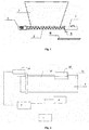
Fig. 1 is a schematic drawing of an automatic feeder according to a first embodiment not claimed by the present invention; -
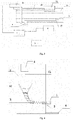
Fig. 2 is a control connection diagram of the automatic feeder of the present invention; -
Fig. 3 is a piping diagram of a water supply system of the automatic feeder of the present invention; -
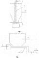
Fig. 4 is a schematic drawing of the automatic feeder according to a second embodiment of the present invention; -
Fig. 5 is a schematic drawing of the automatic feeder according to a third embodiment of the present invention; -
Fig. 6 is a schematic drawing of the automatic feeder according to a fourth embodiment of the present invention; -
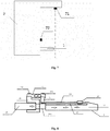
Fig. 7 is a connection diagram of a sensing mode of the automatic feeder of the present invention; -
Fig. 8 is a schematic drawing of the automatic feeder according to a fifth embodiment of the present invention; and -
Fig. 9 is an enlarged diagram of a fixed groove in the schematic drawing according to a fifth embodiment of the automatic feeder of the present invention. - Referring to
Figs. 1 to 9 , the present invention is further illustrated. In the description of the present invention, it should be understood that the orientation or position relations indicated via terms of "longitudinal", "transversal", "upper", "lower", "front", "rear", "left", "right", "vertical", "horizontal", "top", "bottom", "inside", "outside" and the like are based on orientation or the position relations shown in the drawings and they are only used for describing the present invention conveniently and simplify rather than indicating or implying that referred devices or elements must have particular orientations or be constructed and operated with the particular orientation, so that these terms cannot be construed as limiting of the present invention. - In the description of the present specification, the referring terms such as "an embodiment", "some embodiments", "an example", "a specific example" and "some examples" mean that particular features, structures, materials or characteristics described in combination of the embodiments or examples are included in at least one embodiment or example of the present invention. In the specification of the present invention, schematic description of the above terms does not necessarily refer to the same embodiment or example. Furthermore, the described particular features, structures, materials or characteristics can be integrated with any one or more embodiments or examples in a proper manner.
- In the description of the present invention, unless otherwise specified and limited, it should be noted that the terms "mounted", "connected to/with" and "connected" need to be broadly understood, for example, connection may be mechanical connection, electrical connection, communication of inner parts of two elements, direct connection, or indirect connection via an intermediation, and those skilled in the art can understand the specific meaning of the above terms in accordance with specific conditions.
- As shown in
Figs. 1 and 2 , an automatic feeder comprises afeeding pipe 1, ahopper 2, aspiral conveyor 3, amotor 4, awater supply pipeline 5 and acontrol unit 7. A sensor or a switch is triggered to work and thefeeding pipe 1 discharges a feed when a sow or a piglet gnaws agnawing block 12 on thefeeding pipe 1; thehopper 2 is configured to be filled with a dry feed material; thespiral conveyor 3 has one end connected with themotor 4 and the other end placed in thefeeding pipe 1, and thespiral conveyor 3 is configured to convey the dry feed material in thehopper 2 to thefeeding pipe 1; themotor 4 provides power for rotation of thespiral conveyor 3; thewater supply pipeline 5 provides water for mixing the dry feed material in thefeeding pipe 1; and thecontrol unit 7 powers on themotor 4 and opens thewater supply pipeline 5 simultaneously after receiving a triggering signal of a sensor or a switch. - A first working principle of the gnawing
block 12 is as below: a triggering connectinglever 13 is arranged, a gap is reserved between a lower part of one end of the triggering connectinglever 13 and thefeeding pipe 1, the end is fixedly connected with the gnawingblock 12, a lever fulcrum is located on thefeeding pipe 1, and the sensor or the switch is triggered to work when the other end of the triggering connectinglever 13 moves upwards. When a sow or a piglet gnaws the gnawingblock 12, a downward pressure is applied to one end of the triggering connectinglever 13, so that the other end of the triggering connectinglever 13 moves upwards to trigger the senor or the switch to work. The sensor may be a pressure sensor, and the switch may be a travel switch. - A specific connecting structure may be realized as below: a through hole is formed in the
feeding pipe 1 in the axial direction, a circular groove is formed in thefeeding pipe 1 in the extending direction of the through hole, the triggering connectinglever 13 is inserted into the through hole, while a gap is reserved between the triggering connecting lever and the through hole, the front end of the triggering connectinglever 13 is located in the circular groove, another gap is reserved between the lower part of the front end of the triggering connectinglever 13 and the bottom of the circular groove, an upper part of the front end of the triggering connectinglever 13 is fixedly connected to the gnawingblock 12, and the rear end of the triggering connectinglever 13 extends out of thefeeding pipe 1 or is located in another circular groove in thefeeding pipe 1; and when the gnawingblock 12 is pressed down, the rear end of the triggering connectinglever 13 moves upwards to trigger the sensor or the switch to work. - A second working principle of the gnawing
block 12 is as below: a triggering connectinglever 13 is arranged, a through hole is formed in thefeeding pipe 1 in the axial direction, the triggering connectinglever 13 is inserted into the through hole, one end of the triggering connectinglever 13 is fixed onto the wall of thefeeding pipe 1, a gap is reserved between the middle part of the triggering connectinglever 13 and thefeeding pipe 1, the middle part of the triggering connectinglever 13 is connected with the gnawingblock 12, and when the other end of the triggering connectinglever 13 moves downwards, a sensor or a switch is triggered to work. When a sow gnaws the gnawingblock 12 in the middle of the triggering connectinglever 13, a downward pressure is applied to the other end of the triggering connectinglever 13, and the senor or the switch is triggered to work when the other end of the triggering connectinglever 13 moves downwards as one end of the triggering connectinglever 13 is connected with the inner wall of thefeeding pipe 1. The sensor may be a pressure sensor, and the switch may be a travel switch. - A specific connecting structure may be realized as below: a through hole is formed in the
feeding pipe 1 in the axial direction, a circular groove is formed in thefeeding pipe 1 in the extending direction of the through hole, the triggering connectinglever 13 is inserted into the through hole, while a gap is reserved between the triggering connecting lever and the through hole, the end part of the front end of the triggering connectinglever 13 is fixed in the circular groove, another gap is reserved between the other part of the triggering connectinglever 13 and the bottom of the circular groove, the front end of the triggering connectinglever 13 is fixedly connected to the gnawingblock 12, and the rear end of the triggering connectinglever 13 extends out of thefeeding pipe 1 or is located in another circular groove in thefeeding pipe 1; and when the gnawingblock 12 is pressed down, the rear end of the triggering connectinglever 13 moves downwards to trigger the sensor or the switch to work. - A working method of the automatic feeder provided by the present invention is as follows: when being gnawed by a pig, the gnawing
block 12 triggers the sensor or the switch via the triggering connectinglever 13, the sensor or the switch sends a signal to the control unit, the control unit controls themotor 4 to be powered on and thewater supply pipeline 5 to be opened synchronically according to the single output from the sensor or the switch, themotor 4 acts on thespiral conveyor 3 to enable the dry feed material in thehopper 2 to be conveyed to thefeeding pipe 1, thewater supply pipeline 5 conveys drinking water to thefeeding pipe 1 at the same time, and after being mixed, the dry feed material and the drinking water are directly discharged to the mouth of the sow or the piglet to be eaten. - As shown in
Fig. 3 , awater delivery pipeline 15 is connected between a water inlet, entering thefeeding pipe 1, of thewater supply pipeline 5 and a water outlet of thefeeding pipe 1, and is buried in the inner wall of thefeeding pipe 1, and the water outlet of thefeeding pipe 1 is located at the inner wall of a dischargingoutlet 11 of thefeeding pipe 1. Thewater supply pipeline 5 is further connected with a heater configured to heat water in thewater supply pipeline 5. - As shown in
Fig. 4 , the end, connected with themotor 4, of thespiral conveyor 3 is higher than the other end thereof located in thefeeding pipe 1 to prevent water in the water supply pipeline from flowing into thehopper 2. Thespiral conveyor 3 is connected with themotor 4 through amotor rod 41, and stirringvanes 42 for scattering the dry feed material are further arranged on themotor rod 41. Afeed receiving tank 6 is also arranged below the feedingpipe 1. - As shown in
Fig. 5 , themotor 4 may be arranged below thehopper 2, and the end, connected with themotor 4, of thespiral conveyor 3 is lower than the other end thereof located in thefeeding pipe 1, so that the dry feed material moves upwards under the action of the motor, thereby realizing the purposes of the present invention. - As shown in
Fig. 6 , an automatic feeder comprises afeeding pipe 1, ahopper 2, aspiral conveyor 3, amotor 4, awater supply pipeline 5 and acontrol unit 7. Thefeeding pipe 1 discharges a feed when a sow or a piglet gnaws agnawing block 12 thereon, and a sensor or a switch is triggered to work when the gnawingblock 12 is gnawed; thehopper 2 is configured to be filled with a dry feed material; one end of thespiral conveyor 3 is connected with themotor 4, the other end of the spiral conveyor is located in thefeeding pipe 1, and thespiral conveyor 3 is configured to convey the dry feed material in thehopper 2 to thefeeding pipe 1; themotor 4 provides power for rotation of thespiral conveyor 3; thewater supply pipeline 5 provides water for the dry feed material in thefeeding pipe 1 for feed mixing; and after receiving a triggering signal of the sensor or the switch, thecontrol unit 7 controls themotor 4 to be powered on and thewater supply pipeline 5 to be opened simultaneously. Thespiral conveyor 3 adopts a stepped structure, the lower end of the stepped structure is connected with thefeeding pipe 1, and the higher end of the stepped structure is connected with themotor 4. Thespiral conveyor 3 with the stepped structure can also prevent water from entering thehopper 2. - As shown in
Fig. 7 , an automatic feeder comprises afeeding pipe 1, ahopper 2, aspiral conveyor 3, amotor 4, awater supply pipeline 5 and acontrol unit 7; when being gnawed by a sow or a piglet, the feedingpipe 1 discharges a feed as the sow or the piglet triggers infrared sensors; thehopper 2 is configured to be filled with a dry feed material; one end of thespiral conveyor 3 is connected with themotor 4, the other end of the spiral conveyor is located in thefeeding pipe 1, and thespiral conveyor 3 is configured to convey the dry feed material in thehopper 2 to thefeeding pipe 1; themotor 4 provides power for rotation of thespiral conveyor 3; thewater supply pipeline 5 provides water for the dry feed material in thefeeding pipe 1 for feed mixing; after receiving triggering signals of the infrared sensors, thecontrol unit 7 controls themotor 4 to be powered on and thewater supply pipeline 5 to be opened simultaneously; and the infrared sensors comprise a verticalinfrared sensor 71 and a horizontalinfrared sensor 72. The horizontalinfrared sensor 72 and the verticalinfrared sensor 71 can be triggered at the same time when the sow or the piglet gnaws a feeding spout only, and accordingly, themotor 4 is powered on and thewater supply pipeline 5 is opened to convey the dry material feed and water to the sows or the piglets. - As shown in
Fig. 8 , an automatic feeder comprises afeeding pipe 1, ahopper 2, aspiral conveyor 3, amotor 4, awater supply pipeline 5 and acontrol unit 7. Thefeeding pipe 1 discharges a feed when a sow or a piglet gnaws agnawing block 12 thereon, and apressure sensor 14 is triggered when the gnawingblock 12 is gnawed; thehopper 2 is configured to be filled with a dry feed material; one end of thespiral conveyor 3 is connected with themotor 4, the other end of the spiral conveyor is located in thefeeding pipe 1, and thespiral conveyor 3 is configured to convey the dry feed material in thehopper 2 to thefeeding pipe 1; themotor 4 provides power for rotation of thespiral conveyor 3; thewater supply pipeline 5 provides water for the dry feed material in thefeeding pipe 1 for feed mixing; after receiving a triggering signal of thepressure sensor 14, thecontrol unit 7 controls thepressure motor 4 to be powered on and thewater supply pipeline 5 to be opened simultaneously; and when not receiving the triggering signal of thepressure sensor 14, thecontrol unit 7 controls themotor 4 to be powered off and thewater supply pipeline 5 to be closed. - Specifically, a triggering connecting lever mounting
slot hole 16 formed in the dischargingoutlet 11 at the front end of thefeeding pipe 1 in the horizontal direction and a gnawing block mounting groove formed in the discharging outlet in the vertical direction are communicated with each other, one end of the triggering connectinglever 13 is connected to the gnawingblock 12 located in the gnawing block mounting groove, the other end of the triggering connectinglever 13 is fixedly connected to thepressure sensor 14, and a gap is reserved between the triggering connectinglever 13 and the triggering connecting lever mountingslot hole 16; and when the gnawingblock 12 is gnawed, the triggering connectinglever 13 is deformed to trigger thepressure sensor 14 to respond. - The discharging
outlet 11 at the front end of thefeeding pipe 1 is connected with a conveyingpipe 17 at the rear end of thefeeding pipe 1, and thespiral conveyor 3 is arranged in the conveyingpipe 17 at the rear end of thefeeding pipe 1. - The discharging
outlet 11 is connected with the conveyingpipe 17 via a connecting joint 18, and one end of thepressure sensor 14 is fixed to the connecting joint 18. - The triggering connecting
lever 13 is connected with the other end of thepressure sensor 14 via a connectingblock 19. As shown inFig. 9 , a fixedring 192 is arranged at one end of the connectingblock 19, and the triggering connectinglever 13 is inserted into and in interference fit with the fixedring 192; a fixedgroove 191 is formed in the other end of the connectingblock 19, and one end of thepressure sensor 14 is clamped in the fixedgroove 191 and is fixed to the connectingblock 19 via afirst fixing bolt 141; and the other end of thepressure sensor 14 is fixed to the connecting joint 18 via asecond fixing bolt 142. - One end, connected with the
motor 4, of thespiral conveyor 3 is higher than the other end thereof located in thefeeding pipe 1 to prevent water in thewater supply pipeline 5 from flowing into thehopper 2. - The
spiral conveyor 3 is connected with themotor 4 via amotor rod 41, and stirringvanes 42 for scattering the dry feed material are further arranged on themotor rod 41. Thewater supply pipeline 5 is also connected with a heater configured to heat water in thewater supply pipeline 5. - A
water delivery pipeline 15 is connected between a water inlet, entering thefeeding pipe 1, of thewater supply pipeline 5 and a water outlet of thefeeding pipe 1, and is buried in the inner wall of thefeeding pipe 1, and the water outlet of thefeeding pipe 1 is located at the inner wall of the dischargingoutlet 11 of thefeeding pipe 1. - A
feed receiving tank 6 is also arranged below the feedingpipe 1. - It should be noted that the present invention is applicable to not only sows and piglets, but also boars.
- A feeding pipe is provided, wherein: a triggering connecting lever mounting
slot hole 16 axially formed in the pipe wall of a dischargingoutlet 11 at the front end of thefeeding pipe 1 and a gnawing block mounting groove radially formed in the pipe wall of the discharging outlet are communicated with each other, one end of a triggering connectinglever 13 is connected to agnawing block 12 located in the gnawing block mounting groove, the other end of the triggering connectinglever 13 is fixedly connected to apressure sensor 14 or a switch, and a gap is reserved between the triggering connectinglever 13 and the triggering connecting lever mountingslot hole 16; and when the gnawingblock 12 is gnawed, the triggering connectinglever 13 is deformed to trigger thepressure sensor 14 or the switch to respond. - The present invention is exemplarily described in combination with the drawings, while it is clear that the implementation of the present invention is free of limitation of the above-described manners, and various improvements adopting the ideas and the technical solutions of the present invention or the ideas and the technical solutions of the present invention without improvements and applied to other occasions can fall into the protection scope of the present invention, which is defined by the scope of the claims.
REFERENCE NUMERALS 1-Feeding Pipe 11-Discharging outlet 111-Fixed End Part 12-Gnawing Block 13-Triggering Connecting lever 14-Pressure Sensor 141-First Fixing Bolt 142-Second Fixing Bolt 15-Water Delivery Pipeline 16-Triggering Connecting lever Mounting Slot Hole 17-Conveying Pipe 18-Connecting joint 19-Connecting Block 191-Fixed Groove 192-Fixed ring 193-Threaded Hole 2-Hopper 3-Spiral conveyor 4-Motor 41-Motor Rod 42-Stirring Vane 5-Water Supply Pipeline 6-Feed Receiving Tank 7-Control Unit 71-Vertical Infrared Sensor 72-Horizontal Infrared Sensor
Claims (6)
- An automatic feeder comprising a feeding pipe (1) discharging a feed when a pig gnaws a gnawing block (12) thereon and thus triggers a pressure sensor (14) or a switch, a hopper (2) configured to be filled with a dry feed material, a motor (4), a spiral conveyor (3) for conveying the dry feed material in the hopper (2) to the feeding pipe (1) and having one end connected with the motor (4) to receiving its power for rotation and the other end placed in the feeding pipe (1), a water supply pipeline (5) for providing water for mixing the dry feed material in the feeding pipe (1), and a control unit (7) for powering on the motor (4) and opening the water supply pipeline (5) simultaneously after receiving a triggering signal of the pressure sensor (14) or the switch and powering off the motor (4) and closing the water supply pipeline (5) when not receiving the triggering signal of the pressure sensor (14) or the switch, wherein a mounting slot hole (16) of a triggering connecting lever is axially formed in a pipe wall of a discharging outlet (11) at a front end of the feeding pipe (1) and a gnawing block mounting groove is radially formed in the pipe wall of the discharging outlet, the mounting slot hole (16) and the gnawing block mounting groove are communicated with each other; one end of the triggering connecting lever (13) is connected to the gnawing block (12) located in the gnawing block mounting groove, the other end of the triggering connecting lever (13) is fixedly connected to the pressure sensor (14) or the switch; a gap is reserved between the triggering connecting lever (13) and the mounting slot hole (16); and when the gnawing block (12) is gnawed, the triggering connecting lever (13) is deformed to trigger the pressure sensor (14) or the switch to respond, and in that one end, connected with the motor (4), of the spiral conveyor (3) is higher than the other end thereof located in the feeding pipe (1) to prevent water in the water supply pipeline (5) from flowing into the hopper (2), the spiral conveyor (3) is connected with the motor (4) via a motor rod (41), and a stirring vane (42) for scattering the dry feed material is arranged on the motor rod (41).
- The automatic feeder of claim 1, characterized in that the discharging outlet (11) at the front end of the feeding pipe (1) is connected with a conveying pipe (17) at a rear end of the feeding pipe (1), and the spiral conveyor (3) is arranged in the conveying pipe (17) at the rear end of the feeding pipe (1).
- The automatic feeder of claim 1, characterized in that the discharging outlet (11) is connected with the conveying pipe (17) via a connecting joint (18), and the pressure sensor (14) is fixed onto the connecting joint (18).
- The automatic feeder of claim 3, characterized in that the triggering connecting lever (13) is fixedly connected with the pressure sensor (14) via a connecting block (19).
- The automatic feeder of claim 1, characterized in that the water supply pipeline (5) is further connected with a heater configured to heat water in the water supply pipeline (5).
- The automatic feeder of claim 1 or 5, characterized in that a water delivery pipeline (15) is connected between a water inlet, entering the feeding pipe (1), of the water supply pipeline (5) and a water outlet of the feeding pipe (1), and is buried in an inner wall of the feeding pipe (1); and the water outlet of the feeding pipe (1) is located at an inner wall of the discharging outlet (11) of the feeding pipe (1).
Applications Claiming Priority (2)
| Application Number | Priority Date | Filing Date | Title |
|---|---|---|---|
| CN201510102416.9A CN104737935B (en) | 2015-03-10 | 2015-03-10 | The feed pipe of a kind of automatic feeding machine and use thereof |
| PCT/CN2016/000122 WO2016141771A1 (en) | 2015-03-10 | 2016-03-09 | Automatic feeder and feeding tube used thereby |
Publications (3)
| Publication Number | Publication Date |
|---|---|
| EP3269233A1 EP3269233A1 (en) | 2018-01-17 |
| EP3269233A4 EP3269233A4 (en) | 2018-11-21 |
| EP3269233B1 true EP3269233B1 (en) | 2020-08-05 |
Family
ID=53578659
Family Applications (1)
| Application Number | Title | Priority Date | Filing Date |
|---|---|---|---|
| EP16760998.1A Active EP3269233B1 (en) | 2015-03-10 | 2016-03-09 | Automatic feeder with feeding pipe |
Country Status (4)
| Country | Link |
|---|---|
| US (1) | US10342213B2 (en) |
| EP (1) | EP3269233B1 (en) |
| CN (6) | CN105850762B (en) |
| WO (1) | WO2016141771A1 (en) |
Families Citing this family (26)
| Publication number | Priority date | Publication date | Assignee | Title |
|---|---|---|---|---|
| CN105850762B (en) | 2015-03-10 | 2018-06-15 | 嘉兴诺丁汉工业设计有限公司 | A kind of automatic feeding machine |
| CN106489762B (en) * | 2015-11-18 | 2017-08-22 | 宁波设会物联网科技有限公司 | A kind of automatic feeding machine |
| CN108029575B (en) * | 2017-02-07 | 2020-11-10 | 义乌市宏博机械科技有限公司 | Touch switch of feeding start detection system |
| US10336552B1 (en) * | 2017-03-31 | 2019-07-02 | Becs Technology, Inc. | Proximity detector |
| GB2570183B (en) | 2017-11-06 | 2022-08-10 | Peterson Warren | Apparatus and method for loading a pig into a pipeline |
| CN107593484A (en) * | 2017-11-10 | 2018-01-19 | 耒阳市晓田牧业有限责任公司 | A kind of pig drawing-in device |
| CN107646720A (en) * | 2017-11-10 | 2018-02-02 | 耒阳市晓田牧业有限责任公司 | A kind of pig uniform feeder |
| CN107867544A (en) * | 2017-12-05 | 2018-04-03 | 湖北惠泽生物科技股份有限公司 | The feed induction system of operating is automatically stopped after a kind of blocking |
| CN108077094A (en) * | 2018-01-25 | 2018-05-29 | 广州荷德曼农业科技有限公司 | A kind of automatic medicine adding apparatus and Automatic Dosing feeding systems |
| US11062239B2 (en) | 2018-02-17 | 2021-07-13 | Bank Of America Corporation | Structuring computer-mediated communication and determining relevant case type |
| US10614406B2 (en) | 2018-06-18 | 2020-04-07 | Bank Of America Corporation | Core process framework for integrating disparate applications |
| CN108861664A (en) * | 2018-06-25 | 2018-11-23 | 青岛伊克斯达智能装备有限公司 | The feeding device and feed process of the continuous thermal cracking of waste tire |
| CN109392746B (en) * | 2018-11-23 | 2021-08-03 | 佛山科学技术学院 | Novel water-material mixed type trough |
| AT521507B1 (en) * | 2019-03-08 | 2020-02-15 | Ferdinand Leibetseder | Feeder |
| CN109804939B (en) * | 2019-03-21 | 2022-03-22 | 广州影子科技有限公司 | Cultivation system and control method |
| CN110226529A (en) * | 2019-07-17 | 2019-09-13 | 孙元 | A kind of cattle and sheep automatic feeding device |
| US11099122B1 (en) | 2020-02-25 | 2021-08-24 | Becs Technology, Inc. | Proximity detector |
| CN111418515B (en) * | 2020-04-10 | 2024-05-31 | 华南农业大学 | But accurate device of suckleing of remote monitoring's piglet |
| CN111699998A (en) * | 2020-05-19 | 2020-09-25 | 济源市阳光兔业科技有限公司 | Novel drinking water device for rabbits |
| JP7532988B2 (en) * | 2020-07-30 | 2024-08-14 | セイコーエプソン株式会社 | Raw material supply device |
| CN112514824A (en) * | 2020-11-18 | 2021-03-19 | 淮南天陈农业发展有限公司 | Intelligent feeding device |
| CN112715395A (en) * | 2020-12-29 | 2021-04-30 | 泌阳县夏南牛科技开发有限公司 | Automatic feeding device for feeding Xianan cattle |
| CN112889682B (en) * | 2021-03-10 | 2023-01-13 | 长沙兴牧机械有限公司 | Pig is raised and throws edible device with intelligence |
| CN113785781B (en) * | 2021-09-06 | 2022-09-16 | 连云港市畜牧兽医站 | Water supply system for large-scale live pig healthy breeding and water supply method thereof |
| CN113879873B (en) * | 2021-11-09 | 2023-06-09 | 湖南常德南方水泥有限公司 | Coal mill air locking feeder with hot air pipe |
| CN116849144B (en) * | 2023-09-01 | 2023-12-01 | 太行润源食品有限公司 | Intelligent pig farm feed supply device with timing and quantitative functions |
Family Cites Families (22)
| Publication number | Priority date | Publication date | Assignee | Title |
|---|---|---|---|---|
| DE1957732C3 (en) * | 1969-11-17 | 1978-11-02 | Georg 8301 Holzhausen Melzl | Feed distribution device |
| DE2930732A1 (en) * | 1979-07-28 | 1981-02-12 | Christian Trattnig | Automatic feeding device controlled by water clock - has tippable vessel below water tank with outlet releasing water at given rate |
| US4508061A (en) * | 1983-11-15 | 1985-04-02 | David Swearingin | Nipple feeder for dispensing dry feed |
| DE19517283C1 (en) * | 1995-05-11 | 1996-03-07 | Mannebeck B Landtechnik Gmbh | Feeding equipment for pigs |
| CN2847840Y (en) * | 2005-09-16 | 2006-12-20 | 牛延超 | Multifunctional induced feeding device for piglet |
| JP2008029306A (en) * | 2006-07-31 | 2008-02-14 | Fujii Shokai:Kk | Livestock feeder |
| KR100822743B1 (en) * | 2007-05-18 | 2008-04-17 | 홍정표 | An apparatus for providing food for animal |
| US8827542B2 (en) * | 2008-07-28 | 2014-09-09 | Ganado Technologies Corp. | Apparatus and method to feed livestock |
| CN201238525Y (en) * | 2008-05-14 | 2009-05-20 | 莫流阶 | Dry-wet automatic feeder |
| CN202262310U (en) * | 2011-09-14 | 2012-06-06 | 安徽省菩提果牧业科技有限公司 | Fodder feeding device for breed selection and fodder selection machine for pigs |
| KR101353781B1 (en) * | 2012-04-04 | 2014-01-27 | 이창현 | The automatic supply water and feed |
| CN202652974U (en) * | 2012-04-19 | 2013-01-09 | 成都通威自动化设备有限公司 | Piglet feeding device |
| US8944006B2 (en) * | 2012-06-20 | 2015-02-03 | Smart Animal Training Systems, LLC | Animal training device and methods therefor |
| CN202949847U (en) * | 2012-10-08 | 2013-05-29 | 明柱尔 | Automatic feeding device |
| CN203087185U (en) * | 2012-12-21 | 2013-07-31 | 合肥立华畜禽有限公司 | Automatic spiral-conveying feeding system |
| CN103004633A (en) * | 2012-12-21 | 2013-04-03 | 合肥立华畜禽有限公司 | Automatic feeding system through screw conveying |
| CN203058038U (en) * | 2013-03-04 | 2013-07-17 | 河北吴氏润康牧业股份有限公司 | Instant agitating and feeding device |
| CN103202238B (en) * | 2013-03-21 | 2015-07-08 | 郭忠金 | Intellectualized and full automatic porkling trough |
| CN203378389U (en) * | 2013-06-28 | 2014-01-08 | 都嘎日 | Digital feeding machine |
| CN203378391U (en) * | 2013-06-28 | 2014-01-08 | 都嘎日 | Full-automatic herding water trough |
| US10426136B2 (en) * | 2014-08-01 | 2019-10-01 | Calf Smart Limited | Feed apparatus and system |
| CN105850762B (en) * | 2015-03-10 | 2018-06-15 | 嘉兴诺丁汉工业设计有限公司 | A kind of automatic feeding machine |
-
2015
- 2015-03-10 CN CN201610216113.4A patent/CN105850762B/en active Active
- 2015-03-10 CN CN201610216111.5A patent/CN105830941B/en active Active
- 2015-03-10 CN CN201610219601.0A patent/CN105830942B/en active Active
- 2015-03-10 CN CN201510102416.9A patent/CN104737935B/en active Active
- 2015-03-10 CN CN201610219603.XA patent/CN105850763B/en active Active
- 2015-03-10 CN CN201610216112.XA patent/CN105850761B/en active Active
-
2016
- 2016-03-09 US US15/323,478 patent/US10342213B2/en not_active Expired - Fee Related
- 2016-03-09 WO PCT/CN2016/000122 patent/WO2016141771A1/en active Application Filing
- 2016-03-09 EP EP16760998.1A patent/EP3269233B1/en active Active
Non-Patent Citations (1)
| Title |
|---|
| None * |
Also Published As
| Publication number | Publication date |
|---|---|
| CN105830942A (en) | 2016-08-10 |
| CN105850763A (en) | 2016-08-17 |
| CN105850761A (en) | 2016-08-17 |
| EP3269233A1 (en) | 2018-01-17 |
| CN105850762A (en) | 2016-08-17 |
| CN105850762B (en) | 2018-06-15 |
| WO2016141771A1 (en) | 2016-09-15 |
| CN104737935B (en) | 2016-03-02 |
| CN105850763B (en) | 2018-09-14 |
| US20170142930A1 (en) | 2017-05-25 |
| CN105830942B (en) | 2018-08-14 |
| CN104737935A (en) | 2015-07-01 |
| EP3269233A4 (en) | 2018-11-21 |
| CN105830941A (en) | 2016-08-10 |
| US10342213B2 (en) | 2019-07-09 |
| CN105850761B (en) | 2018-08-17 |
| CN105830941B (en) | 2018-09-28 |
Similar Documents
| Publication | Publication Date | Title |
|---|---|---|
| EP3269233B1 (en) | Automatic feeder with feeding pipe | |
| CN105393929B (en) | A kind of automatic feeding machine | |
| KR101779304B1 (en) | Solving method of meal in water for swine breeding device | |
| PL184194B1 (en) | Livestock feeding apparatus especially for feeding swine | |
| CN205337176U (en) | Pig is with feed case that wets futilely | |
| KR101889407B1 (en) | feeding apparatus and operation method using the same, feeding system for domestic animal | |
| KR20090092748A (en) | Pig Square Liquid Feeder | |
| KR101825128B1 (en) | System for feeding liquefied feed for pig farming | |
| CN107568074B (en) | Breeding pig house | |
| US3168888A (en) | Method of feeding dairy cows | |
| CN212184651U (en) | Automatic pig house feed and drinking water supply system | |
| CN112119926A (en) | Automatic feeder | |
| CN109349124B (en) | Conservation swinery | |
| CN107926718B (en) | Elevated bed pig house of intelligence | |
| CN217936823U (en) | Piglet is bred with raising young case | |
| CN219631211U (en) | Excrement treatment device for henhouse | |
| CN205389906U (en) | Feeding equipment | |
| CN210328898U (en) | Meat rabbit is with breeding case | |
| KR102059774B1 (en) | Liquid feed supply method of feeding for pig | |
| CN108308047A (en) | A kind of small-sized liquid feeding device and application method | |
| CN113661935B (en) | Farming and grazing farm cultivation feed feeding timing conveying equipment | |
| CN216018457U (en) | Feeding and disinfecting system for livestock breeding | |
| CN215302244U (en) | A throw material device for livestock-raising | |
| Hessel et al. | The feed level controlled mash feeder vs. conventional tube mash feeder: Performance and eating behaviour of young weaned piglets | |
| CN216393002U (en) | Bulk feed mixing transport vehicle |
Legal Events
| Date | Code | Title | Description |
|---|---|---|---|
| STAA | Information on the status of an ep patent application or granted ep patent |
Free format text: STATUS: THE INTERNATIONAL PUBLICATION HAS BEEN MADE |
|
| PUAI | Public reference made under article 153(3) epc to a published international application that has entered the european phase |
Free format text: ORIGINAL CODE: 0009012 |
|
| STAA | Information on the status of an ep patent application or granted ep patent |
Free format text: STATUS: REQUEST FOR EXAMINATION WAS MADE |
|
| 17P | Request for examination filed |
Effective date: 20170109 |
|
| AK | Designated contracting states |
Kind code of ref document: A1 Designated state(s): AL AT BE BG CH CY CZ DE DK EE ES FI FR GB GR HR HU IE IS IT LI LT LU LV MC MK MT NL NO PL PT RO RS SE SI SK SM TR |
|
| AX | Request for extension of the european patent |
Extension state: BA ME |
|
| DAV | Request for validation of the european patent (deleted) | ||
| DAX | Request for extension of the european patent (deleted) | ||
| A4 | Supplementary search report drawn up and despatched |
Effective date: 20181022 |
|
| RIC1 | Information provided on ipc code assigned before grant |
Ipc: A01K 5/02 20060101AFI20181016BHEP Ipc: A01K 7/06 20060101ALI20181016BHEP Ipc: A01K 5/00 20060101ALI20181016BHEP |
|
| RIC1 | Information provided on ipc code assigned before grant |
Ipc: A01K 5/02 20060101AFI20191030BHEP Ipc: A01K 7/06 20060101ALI20191030BHEP |
|
| GRAP | Despatch of communication of intention to grant a patent |
Free format text: ORIGINAL CODE: EPIDOSNIGR1 |
|
| STAA | Information on the status of an ep patent application or granted ep patent |
Free format text: STATUS: GRANT OF PATENT IS INTENDED |
|
| INTG | Intention to grant announced |
Effective date: 20191219 |
|
| RIN1 | Information on inventor provided before grant (corrected) |
Inventor name: BIAN, FENG Inventor name: ZOU, PING Inventor name: ZHONG, RIKAI Inventor name: YU, LI Inventor name: CHEN, DINGGAN Inventor name: WANG, KAIYUN Inventor name: ZHOU, HONG Inventor name: GENG, WEI Inventor name: CAO, JIANSHENG Inventor name: HUANG, RUISEN Inventor name: ZHONG, WEICHAO Inventor name: YANG, HUIYONG Inventor name: LIU, ZHENGHUA Inventor name: LUO, TUYU Inventor name: ZHANG, RONGBO |
|
| GRAS | Grant fee paid |
Free format text: ORIGINAL CODE: EPIDOSNIGR3 |
|
| RIN1 | Information on inventor provided before grant (corrected) |
Inventor name: ZHONG, WEICHAO Inventor name: CAO, JIANSHENG Inventor name: ZHONG, RIKAI Inventor name: YANG, HUIYONG Inventor name: LUO, TUYU Inventor name: ZHANG, RONGBO Inventor name: CHEN, DINGGAN Inventor name: ZHOU, HONG Inventor name: BIAN, FENG Inventor name: WANG, KAIYUN Inventor name: GENG, WEI |
|
| RAP1 | Party data changed (applicant data changed or rights of an application transferred) |
Owner name: GUANGZHOU MUYIFENG ANIMAL HUSBANDRY TECHNOLOGY LTD. Owner name: GUANGDONG PROVINCE MODERN AGRICULTURAL EQUIPMENT RESEARCH INSTITUTE |
|
| GRAA | (expected) grant |
Free format text: ORIGINAL CODE: 0009210 |
|
| STAA | Information on the status of an ep patent application or granted ep patent |
Free format text: STATUS: THE PATENT HAS BEEN GRANTED |
|
| AK | Designated contracting states |
Kind code of ref document: B1 Designated state(s): AL AT BE BG CH CY CZ DE DK EE ES FI FR GB GR HR HU IE IS IT LI LT LU LV MC MK MT NL NO PL PT RO RS SE SI SK SM TR |
|
| REG | Reference to a national code |
Ref country code: GB Ref legal event code: FG4D |
|
| REG | Reference to a national code |
Ref country code: CH Ref legal event code: EP |
|
| REG | Reference to a national code |
Ref country code: AT Ref legal event code: REF Ref document number: 1297416 Country of ref document: AT Kind code of ref document: T Effective date: 20200815 |
|
| REG | Reference to a national code |
Ref country code: IE Ref legal event code: FG4D |
|
| REG | Reference to a national code |
Ref country code: DE Ref legal event code: R096 Ref document number: 602016041417 Country of ref document: DE |
|
| REG | Reference to a national code |
Ref country code: LT Ref legal event code: MG4D |
|
| REG | Reference to a national code |
Ref country code: NL Ref legal event code: MP Effective date: 20200805 |
|
| REG | Reference to a national code |
Ref country code: AT Ref legal event code: MK05 Ref document number: 1297416 Country of ref document: AT Kind code of ref document: T Effective date: 20200805 |
|
| PG25 | Lapsed in a contracting state [announced via postgrant information from national office to epo] |
Ref country code: HR Free format text: LAPSE BECAUSE OF FAILURE TO SUBMIT A TRANSLATION OF THE DESCRIPTION OR TO PAY THE FEE WITHIN THE PRESCRIBED TIME-LIMIT Effective date: 20200805 Ref country code: BG Free format text: LAPSE BECAUSE OF FAILURE TO SUBMIT A TRANSLATION OF THE DESCRIPTION OR TO PAY THE FEE WITHIN THE PRESCRIBED TIME-LIMIT Effective date: 20201105 Ref country code: LT Free format text: LAPSE BECAUSE OF FAILURE TO SUBMIT A TRANSLATION OF THE DESCRIPTION OR TO PAY THE FEE WITHIN THE PRESCRIBED TIME-LIMIT Effective date: 20200805 Ref country code: ES Free format text: LAPSE BECAUSE OF FAILURE TO SUBMIT A TRANSLATION OF THE DESCRIPTION OR TO PAY THE FEE WITHIN THE PRESCRIBED TIME-LIMIT Effective date: 20200805 Ref country code: PT Free format text: LAPSE BECAUSE OF FAILURE TO SUBMIT A TRANSLATION OF THE DESCRIPTION OR TO PAY THE FEE WITHIN THE PRESCRIBED TIME-LIMIT Effective date: 20201207 Ref country code: SE Free format text: LAPSE BECAUSE OF FAILURE TO SUBMIT A TRANSLATION OF THE DESCRIPTION OR TO PAY THE FEE WITHIN THE PRESCRIBED TIME-LIMIT Effective date: 20200805 Ref country code: AT Free format text: LAPSE BECAUSE OF FAILURE TO SUBMIT A TRANSLATION OF THE DESCRIPTION OR TO PAY THE FEE WITHIN THE PRESCRIBED TIME-LIMIT Effective date: 20200805 Ref country code: NO Free format text: LAPSE BECAUSE OF FAILURE TO SUBMIT A TRANSLATION OF THE DESCRIPTION OR TO PAY THE FEE WITHIN THE PRESCRIBED TIME-LIMIT Effective date: 20201105 Ref country code: FI Free format text: LAPSE BECAUSE OF FAILURE TO SUBMIT A TRANSLATION OF THE DESCRIPTION OR TO PAY THE FEE WITHIN THE PRESCRIBED TIME-LIMIT Effective date: 20200805 Ref country code: GR Free format text: LAPSE BECAUSE OF FAILURE TO SUBMIT A TRANSLATION OF THE DESCRIPTION OR TO PAY THE FEE WITHIN THE PRESCRIBED TIME-LIMIT Effective date: 20201106 |
|
| PG25 | Lapsed in a contracting state [announced via postgrant information from national office to epo] |
Ref country code: PL Free format text: LAPSE BECAUSE OF FAILURE TO SUBMIT A TRANSLATION OF THE DESCRIPTION OR TO PAY THE FEE WITHIN THE PRESCRIBED TIME-LIMIT Effective date: 20200805 Ref country code: RS Free format text: LAPSE BECAUSE OF FAILURE TO SUBMIT A TRANSLATION OF THE DESCRIPTION OR TO PAY THE FEE WITHIN THE PRESCRIBED TIME-LIMIT Effective date: 20200805 Ref country code: NL Free format text: LAPSE BECAUSE OF FAILURE TO SUBMIT A TRANSLATION OF THE DESCRIPTION OR TO PAY THE FEE WITHIN THE PRESCRIBED TIME-LIMIT Effective date: 20200805 Ref country code: LV Free format text: LAPSE BECAUSE OF FAILURE TO SUBMIT A TRANSLATION OF THE DESCRIPTION OR TO PAY THE FEE WITHIN THE PRESCRIBED TIME-LIMIT Effective date: 20200805 Ref country code: IS Free format text: LAPSE BECAUSE OF FAILURE TO SUBMIT A TRANSLATION OF THE DESCRIPTION OR TO PAY THE FEE WITHIN THE PRESCRIBED TIME-LIMIT Effective date: 20201205 |
|
| PG25 | Lapsed in a contracting state [announced via postgrant information from national office to epo] |
Ref country code: CZ Free format text: LAPSE BECAUSE OF FAILURE TO SUBMIT A TRANSLATION OF THE DESCRIPTION OR TO PAY THE FEE WITHIN THE PRESCRIBED TIME-LIMIT Effective date: 20200805 Ref country code: DK Free format text: LAPSE BECAUSE OF FAILURE TO SUBMIT A TRANSLATION OF THE DESCRIPTION OR TO PAY THE FEE WITHIN THE PRESCRIBED TIME-LIMIT Effective date: 20200805 Ref country code: RO Free format text: LAPSE BECAUSE OF FAILURE TO SUBMIT A TRANSLATION OF THE DESCRIPTION OR TO PAY THE FEE WITHIN THE PRESCRIBED TIME-LIMIT Effective date: 20200805 Ref country code: SM Free format text: LAPSE BECAUSE OF FAILURE TO SUBMIT A TRANSLATION OF THE DESCRIPTION OR TO PAY THE FEE WITHIN THE PRESCRIBED TIME-LIMIT Effective date: 20200805 Ref country code: EE Free format text: LAPSE BECAUSE OF FAILURE TO SUBMIT A TRANSLATION OF THE DESCRIPTION OR TO PAY THE FEE WITHIN THE PRESCRIBED TIME-LIMIT Effective date: 20200805 |
|
| PGFP | Annual fee paid to national office [announced via postgrant information from national office to epo] |
Ref country code: FR Payment date: 20210330 Year of fee payment: 6 |
|
| REG | Reference to a national code |
Ref country code: DE Ref legal event code: R097 Ref document number: 602016041417 Country of ref document: DE |
|
| PG25 | Lapsed in a contracting state [announced via postgrant information from national office to epo] |
Ref country code: AL Free format text: LAPSE BECAUSE OF FAILURE TO SUBMIT A TRANSLATION OF THE DESCRIPTION OR TO PAY THE FEE WITHIN THE PRESCRIBED TIME-LIMIT Effective date: 20200805 |
|
| PGFP | Annual fee paid to national office [announced via postgrant information from national office to epo] |
Ref country code: DE Payment date: 20210326 Year of fee payment: 6 |
|
| PLBE | No opposition filed within time limit |
Free format text: ORIGINAL CODE: 0009261 |
|
| STAA | Information on the status of an ep patent application or granted ep patent |
Free format text: STATUS: NO OPPOSITION FILED WITHIN TIME LIMIT |
|
| PG25 | Lapsed in a contracting state [announced via postgrant information from national office to epo] |
Ref country code: SK Free format text: LAPSE BECAUSE OF FAILURE TO SUBMIT A TRANSLATION OF THE DESCRIPTION OR TO PAY THE FEE WITHIN THE PRESCRIBED TIME-LIMIT Effective date: 20200805 |
|
| 26N | No opposition filed |
Effective date: 20210507 |
|
| PG25 | Lapsed in a contracting state [announced via postgrant information from national office to epo] |
Ref country code: IT Free format text: LAPSE BECAUSE OF FAILURE TO SUBMIT A TRANSLATION OF THE DESCRIPTION OR TO PAY THE FEE WITHIN THE PRESCRIBED TIME-LIMIT Effective date: 20200805 |
|
| PG25 | Lapsed in a contracting state [announced via postgrant information from national office to epo] |
Ref country code: SI Free format text: LAPSE BECAUSE OF FAILURE TO SUBMIT A TRANSLATION OF THE DESCRIPTION OR TO PAY THE FEE WITHIN THE PRESCRIBED TIME-LIMIT Effective date: 20200805 |
|
| PG25 | Lapsed in a contracting state [announced via postgrant information from national office to epo] |
Ref country code: MC Free format text: LAPSE BECAUSE OF FAILURE TO SUBMIT A TRANSLATION OF THE DESCRIPTION OR TO PAY THE FEE WITHIN THE PRESCRIBED TIME-LIMIT Effective date: 20200805 |
|
| REG | Reference to a national code |
Ref country code: CH Ref legal event code: PL |
|
| GBPC | Gb: european patent ceased through non-payment of renewal fee |
Effective date: 20210309 |
|
| REG | Reference to a national code |
Ref country code: BE Ref legal event code: MM Effective date: 20210331 |
|
| PG25 | Lapsed in a contracting state [announced via postgrant information from national office to epo] |
Ref country code: LU Free format text: LAPSE BECAUSE OF NON-PAYMENT OF DUE FEES Effective date: 20210309 Ref country code: LI Free format text: LAPSE BECAUSE OF NON-PAYMENT OF DUE FEES Effective date: 20210331 Ref country code: CH Free format text: LAPSE BECAUSE OF NON-PAYMENT OF DUE FEES Effective date: 20210331 Ref country code: IE Free format text: LAPSE BECAUSE OF NON-PAYMENT OF DUE FEES Effective date: 20210309 Ref country code: GB Free format text: LAPSE BECAUSE OF NON-PAYMENT OF DUE FEES Effective date: 20210309 |
|
| PG25 | Lapsed in a contracting state [announced via postgrant information from national office to epo] |
Ref country code: BE Free format text: LAPSE BECAUSE OF NON-PAYMENT OF DUE FEES Effective date: 20210331 |
|
| REG | Reference to a national code |
Ref country code: DE Ref legal event code: R119 Ref document number: 602016041417 Country of ref document: DE |
|
| PG25 | Lapsed in a contracting state [announced via postgrant information from national office to epo] |
Ref country code: FR Free format text: LAPSE BECAUSE OF NON-PAYMENT OF DUE FEES Effective date: 20220331 Ref country code: DE Free format text: LAPSE BECAUSE OF NON-PAYMENT OF DUE FEES Effective date: 20221001 |
|
| PG25 | Lapsed in a contracting state [announced via postgrant information from national office to epo] |
Ref country code: CY Free format text: LAPSE BECAUSE OF FAILURE TO SUBMIT A TRANSLATION OF THE DESCRIPTION OR TO PAY THE FEE WITHIN THE PRESCRIBED TIME-LIMIT Effective date: 20200805 |
|
| PG25 | Lapsed in a contracting state [announced via postgrant information from national office to epo] |
Ref country code: HU Free format text: LAPSE BECAUSE OF FAILURE TO SUBMIT A TRANSLATION OF THE DESCRIPTION OR TO PAY THE FEE WITHIN THE PRESCRIBED TIME-LIMIT; INVALID AB INITIO Effective date: 20160309 |
|
| PG25 | Lapsed in a contracting state [announced via postgrant information from national office to epo] |
Ref country code: MK Free format text: LAPSE BECAUSE OF FAILURE TO SUBMIT A TRANSLATION OF THE DESCRIPTION OR TO PAY THE FEE WITHIN THE PRESCRIBED TIME-LIMIT Effective date: 20200805 |