EP3268656B1 - Antriebspaket - Google Patents
Antriebspaket Download PDFInfo
- Publication number
- EP3268656B1 EP3268656B1 EP16707387.3A EP16707387A EP3268656B1 EP 3268656 B1 EP3268656 B1 EP 3268656B1 EP 16707387 A EP16707387 A EP 16707387A EP 3268656 B1 EP3268656 B1 EP 3268656B1
- Authority
- EP
- European Patent Office
- Prior art keywords
- rotor shaft
- supporting
- motor
- support
- drive package
- Prior art date
- Legal status (The legal status is an assumption and is not a legal conclusion. Google has not performed a legal analysis and makes no representation as to the accuracy of the status listed.)
- Active
Links
- 239000002184 metal Substances 0.000 claims description 37
- 229910052751 metal Inorganic materials 0.000 claims description 37
- 230000008878 coupling Effects 0.000 claims description 13
- 238000010168 coupling process Methods 0.000 claims description 13
- 238000005859 coupling reaction Methods 0.000 claims description 13
- 238000007688 edging Methods 0.000 claims description 5
- 239000012530 fluid Substances 0.000 claims description 5
- 238000003466 welding Methods 0.000 claims description 5
- 230000005540 biological transmission Effects 0.000 description 35
- 238000004519 manufacturing process Methods 0.000 description 9
- 239000000463 material Substances 0.000 description 9
- 230000007613 environmental effect Effects 0.000 description 7
- 238000000034 method Methods 0.000 description 6
- XEEYBQQBJWHFJM-UHFFFAOYSA-N Iron Chemical compound [Fe] XEEYBQQBJWHFJM-UHFFFAOYSA-N 0.000 description 4
- 238000005452 bending Methods 0.000 description 3
- 238000005520 cutting process Methods 0.000 description 3
- 229910000831 Steel Inorganic materials 0.000 description 2
- 239000011248 coating agent Substances 0.000 description 2
- 238000000576 coating method Methods 0.000 description 2
- 238000009434 installation Methods 0.000 description 2
- 229910052742 iron Inorganic materials 0.000 description 2
- 238000003698 laser cutting Methods 0.000 description 2
- 239000000843 powder Substances 0.000 description 2
- 238000004080 punching Methods 0.000 description 2
- 230000000284 resting effect Effects 0.000 description 2
- 239000010935 stainless steel Substances 0.000 description 2
- 229910001220 stainless steel Inorganic materials 0.000 description 2
- 239000010959 steel Substances 0.000 description 2
- 229910000851 Alloy steel Inorganic materials 0.000 description 1
- 230000007797 corrosion Effects 0.000 description 1
- 238000005260 corrosion Methods 0.000 description 1
- 230000001419 dependent effect Effects 0.000 description 1
- 238000009826 distribution Methods 0.000 description 1
- 230000005284 excitation Effects 0.000 description 1
- 238000005246 galvanizing Methods 0.000 description 1
- 239000011265 semifinished product Substances 0.000 description 1
- 230000035939 shock Effects 0.000 description 1
Images


Classifications
-
- F—MECHANICAL ENGINEERING; LIGHTING; HEATING; WEAPONS; BLASTING
- F16—ENGINEERING ELEMENTS AND UNITS; GENERAL MEASURES FOR PRODUCING AND MAINTAINING EFFECTIVE FUNCTIONING OF MACHINES OR INSTALLATIONS; THERMAL INSULATION IN GENERAL
- F16H—GEARING
- F16H57/00—General details of gearing
- F16H57/02—Gearboxes; Mounting gearing therein
- F16H57/025—Support of gearboxes, e.g. torque arms, or attachment to other devices
-
- F—MECHANICAL ENGINEERING; LIGHTING; HEATING; WEAPONS; BLASTING
- F16—ENGINEERING ELEMENTS AND UNITS; GENERAL MEASURES FOR PRODUCING AND MAINTAINING EFFECTIVE FUNCTIONING OF MACHINES OR INSTALLATIONS; THERMAL INSULATION IN GENERAL
- F16M—FRAMES, CASINGS OR BEDS OF ENGINES, MACHINES OR APPARATUS, NOT SPECIFIC TO ENGINES, MACHINES OR APPARATUS PROVIDED FOR ELSEWHERE; STANDS; SUPPORTS
- F16M1/00—Frames or casings of engines, machines or apparatus; Frames serving as machinery beds
- F16M1/08—Frames or casings of engines, machines or apparatus; Frames serving as machinery beds characterised by being built-up of sheet material or welded parts
-
- F—MECHANICAL ENGINEERING; LIGHTING; HEATING; WEAPONS; BLASTING
- F16—ENGINEERING ELEMENTS AND UNITS; GENERAL MEASURES FOR PRODUCING AND MAINTAINING EFFECTIVE FUNCTIONING OF MACHINES OR INSTALLATIONS; THERMAL INSULATION IN GENERAL
- F16M—FRAMES, CASINGS OR BEDS OF ENGINES, MACHINES OR APPARATUS, NOT SPECIFIC TO ENGINES, MACHINES OR APPARATUS PROVIDED FOR ELSEWHERE; STANDS; SUPPORTS
- F16M5/00—Engine beds, i.e. means for supporting engines or machines on foundations
-
- F—MECHANICAL ENGINEERING; LIGHTING; HEATING; WEAPONS; BLASTING
- F16—ENGINEERING ELEMENTS AND UNITS; GENERAL MEASURES FOR PRODUCING AND MAINTAINING EFFECTIVE FUNCTIONING OF MACHINES OR INSTALLATIONS; THERMAL INSULATION IN GENERAL
- F16M—FRAMES, CASINGS OR BEDS OF ENGINES, MACHINES OR APPARATUS, NOT SPECIFIC TO ENGINES, MACHINES OR APPARATUS PROVIDED FOR ELSEWHERE; STANDS; SUPPORTS
- F16M1/00—Frames or casings of engines, machines or apparatus; Frames serving as machinery beds
Definitions
- the invention relates to a drive package.
- the DE 33 07 923 A1 shows a base plate for machine units.
- the GB 2 142 411 A shows an assembly for mounting a belt drive.
- the invention is therefore the object of developing a drive package, the environmental protection to be improved.
- the support structure has a support part with a gearbox support section and a motor support part, wherein the support part and the transmission support section are made in one piece, the motor being mounted on the support structure by means of the motor support part, in particular with the motor support part being arranged between the motor and the support part, wherein the transmission is supported on the transmission support portion and connected to the support structure by means of the transmission support portion, wherein the support member is a sheet metal part, wherein the motor support part is a sheet metal part, the support part extending further in the rotor shaft axis direction than in the transverse direction to the rotor shaft axis direction, wherein the motor support part extends further in the transverse direction to the rotor shaft axis direction than in the rotor shaft axial direction.
- the advantage here is that the support structure made of sheet metal parts is compact and easy to carry out.
- the resonant frequency of the support structure is outside the usual motor excitation frequency.
- Sheet metal parts for the production of the support structure can be stored to save space and cut to size in a working cut to the specific combination of engine and transmission.
- the height of the rotor shaft of the motor and of the drive shaft of the transmission are adaptable to one another by the support part having different heights for the motor support part and the transmission support section.
- the motor support part and the support member can be produced as stamped parts or stamped and bent parts in a simple manner with high precision. This eliminates a costly reworking of the support structure, for example by means of grinding.
- the pattern for the parts of the support member in a simple manner is transferable to different sizes of supporting parts or different sheet materials.
- a high process reliability is possible, since the pattern is one-to-one transferable.
- the advantage here is further that the Gereteierlageabites is manufacturable in a manufacturing step with the support member.
- the angled executed Gereteetzlageabites By means of the angled executed Gereteetzlageabitess the torsional stiffness and vibration resistance of the support structure is further improved.
- the support structure has a foot part, wherein the support structure is supported by means of the foot part, in particular on a base, in particular floor, wherein the motor support part and the foot part are made similar, in particular identical.
- the advantage here is that the support structure by means of the foot is tilt-safe on the pad can be arranged.
- a modular system with reduced number of parts is made possible by the reusability of the engine support parts as foot parts.
- Engine support parts and foot parts are reasonably priced.
- the environmental protection is improved.
- the foot part extends in the transverse direction to the rotor shaft axis direction further than in Rotorwellenachsraum.
- the advantage here is that by means of the foot part, the torsional stiffness and vibration resistance of the support structure is further improved.
- the motor support part and the foot part in each case a first recess and a second recess, wherein the motor is connected by means of a guided through the first recess fastener with the support structure, in particular wherein the first recess is designed as a slot, in particular the extends in the rotor shaft axis direction further than in the transverse direction to the rotor shaft axis direction, wherein the support structure by means of a guided through the second recess fastener on a base, in particular bottom, is mountable.
- the advantage here is that by means of the first recess of the axial distance between the engine and clutch is variable and the clutch clearance is adjustable.
- the recesses can be manufactured in one step with the motor support part or the foot part as a stamped part.
- the production cost is reducible and environmental protection is improved.
- the support part and / or the motor support part and / or the foot part is / are designed as a bent part, in particular as a stamped and bent part, in particular as an angle sheet metal part.
- the advantage here is that bending parts have improved rigidity, in particular torsional stiffness, as flat sheet metal parts.
- the sheet metal parts are thinner and material and weight can be saved. Thus, the environmental protection is improved.
- the support member has two sections, which are arranged at a non-disappearing angle to each other, in particular wherein this angle between 90 ° and 180 °, in particular between 135 ° and 180 °, in particular between 150 ° and 170 °, wherein between These subsections a Kantungsabites is arranged, which extends in Rotorwellenachsraum completely through the support member.
- the advantage here is that the torsional rigidity of the support structure is further improved.
- the support member is thinner executable and environmental protection is improved.
- the motor support part and / or the foot part are positively and materially connected to the support member, in particular welded connected.
- the advantage here is that welds between the motor support part or the foot part and the support member are executable smaller than in a only cohesive connection. Thus, material is saving and the support structure is easier to carry out.
- the support part has at least one positioning groove for connection to the motor support part or the foot part.
- the positioning groove in a manufacturing step with the support member can be manufactured, in particular cut or punched.
- the support member has a support portion, in particular extending from the engine to the transmission, wherein the Gerete Miltonlageabêt is arranged at a non-vanishing angle to the support portion, in particular wherein the Gereteetzlageabêt is arranged at right angles to the support portion.
- the Gereteetzlageabrough in rotor shaft axis direction extends further than in the transverse direction to the rotor shaft axis.
- the advantage here is that the torsional stiffness and vibration resistance of the support structure are further improved.
- the support member has a bottom portion, wherein the bottom portion is arranged at a non-vanishing angle to the support portion, in particular wherein the angle between the bottom portion and the support portion is greater than or equal to 90 °, in particular between 90 ° and 180 °, in particular between 90 ° and 135 °, in particular between 100 ° and 120 °.
- the advantage here is that torsional stiffness and vibration resistance of the support structure are further improved.
- the bottom portion between two support sections is arranged, in particular wherein the support member has a substantially U-shaped cross-section having.
- the advantage here is that the support member is hollow executable between the legs of the U, thus weight can be saved. Environmental protection is improved.
- a torque arm is connected by means of a torque support plate to the support structure, wherein the torque support plate is positively connected to the support member, in particular 29apft, in particular positively and materially connected, wherein the torque arm is releasably connected to the torque support plate, in particular by means of a screw connection.
- the drive package is connected by means of the torque arm with an application. The torque arm derives a torque acting on the drive package.
- the torque support plate is materially and positively connected to the support structure.
- the resistance of the torque support plate against lateral forces is improved because the positive connection makes it difficult to tear off the torque support plate of the support member.
- the support structure on a sheet metal part, which is at least partially disposed between two Getriebeauflageabitesen, wherein the sheet metal part is designed as a bent part.
- the sheet metal part transverse to the rotor shaft axis extending edging portions.
- the support member is designed in two pieces, two halves of the support member are materially interconnected, in particular welded, in particular wherein the support member has a linear weld, in particular I-seam, in particular extending in Rotorwellenachsraum.
- the advantage here is that the support member is bendable in a simple manner and then welded.
- the weld is interrupted by means of at least one recess, in particular one in Rotorwellenachscardi further than in the Transverse to the rotor shaft axis extending recess.
- superfluous material during powder coating or hot-dip galvanizing by means of the recess can be discharged, so that further material can be saved.
- the two halves of the support member are mirror-symmetrical to each other.
- the advantage here is that the two halves of the support member can be acted upon evenly with weight and torque.
- the two halves can be produced with the same punching tool.
- tools are saving and environmental protection is improved.
- the drive package has a clutch, in particular a fluid coupling, wherein the coupling connects the rotor shaft of the motor and a driving shaft of the transmission with each other, wherein the support structure has a trough, which covers the area covered by the coupling in Rotorwellenachsraum.
- the tub is materially connected to the support member, in particular welded connected.
- the advantage here is that the tub further improves the torsional stiffness and vibration resistance of the support structure.
- the drive package to a fan, wherein the fan is arranged in Rotorwellenachscardi between the clutch and the transmission, wherein a fan of the fan is rotatably connected to the driving shaft of the transmission.
- the advantage here is that the transmission is coolable by means of the fan.
- the drive package is compact executable. An additional fan motor can be saved.
- the support structure recesses, in particular transport holes, wherein the recesses as a punched or cut recesses are executed.
- the advantage here is that the recesses are punched or cut in a manufacturing step with the support member.
- the recesses are designed as suitable transport eyelets or for receiving prongs of a forklift.
- the advantage here is that the drive package can be fixed for transport by means of the recesses. Additional eyebolts or subsequently introduced cutouts can be saved.
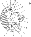
- FIGS. 1 . 2 . 9 and 10 is the first embodiment of the drive package according to the invention shown.
- FIGS. 6 . 7 and 8th is the third embodiment of the drive package according to the invention shown.
- drive package 1 has a motor 2, a transmission 3 and a support structure 5. It is designed as a motor swingarm.
- the motor 2 has a rotor shaft.
- the rotor shaft defines a rotor shaft axis direction.
- a transverse direction to the rotor shaft axis direction is defined as the horizontal transverse direction, in particular extending transversely to the weight of the drive package.
- the support structure 5 has a support part 15 with two transmission support sections (7, 20) and two motor support parts (6, 19).
- the transmission 3 is mounted.
- the Gereteierlageabête (7, 20) each have at least one recess 25.
- the recess 25 is punched or laser-cut or autogenously cut or plasma-cut in one operation with the support member 15.
- the transmission 3 is releasably connected by means of a fastening element 8, in particular screw means, which is guided through a bore in the housing of the transmission 3 and the recess 25 , with the respective Getriebeauflageabêt (7, 20).
- the motor support parts (6, 19) in each case at least one recess 32, preferably oblong hole, which is punched or laser cut in one operation with the respective motor support part (6, 19).
- the slot extends further in the rotor shaft axis direction than in the transverse direction to the rotor shaft axis direction.
- each motor support part (6, 19) has two recesses 32, wherein the support part 15 is arranged between the recesses 32 in this transverse direction to the rotor shaft axis direction.
- the motor 2 is releasably connected to the respective motor support part (6, 19) by means of a fastening element 17, 27, in particular screw means, which is guided through a bore in a foot part 9 of the motor 2 and through the recess 32.
- intermediate plates are arranged to align the engine in the vertical direction.
- the sheet thickness of the intermediate plates is 1 mm to 5 mm.
- the support member 15 is designed as a sheet metal part.
- the support member 15 is designed as a stamped sheet metal part or produced by means of a cutting process, in particular by means of a laser cutting process.
- the support member 15 is made in a single operation with grooves and recesses in the support member 15.
- the support member 15 has the Gerete Miltonlageabête (7, 20), two support portions 23 and a bottom portion 24.
- the bottom portion 24 connects the two support portions 23.
- the support member 15 has a substantially U-shaped cross-section.
- the bottom portion 24 is disposed at a non-zero angle to the respective support portion 23.
- the angle between the bottom portion 24 and the respective support portion 23 is greater than or equal to 90 °, in particular between 90 ° and 180 °, in particular between 90 ° and 135 °, in particular between 100 ° and 120 °.
- the bottom portion 24 is arranged folded relative to the support portion 23. Between the bottom portion 24 and the support portion 23 a Kantungsabêt 22 is arranged, which extends in Rotorwellenachsutter.
- the support sections 23 each have an edging section 21 which extends in the direction of the rotor shaft axis through the entire support part 15. Two sections of each support section 23, which are interconnected by means of the edging section 21, so are arranged at a non-zero angle to each other. This angle is between 90 ° and 180 °, in particular between 135 ° and 180 °, in particular between 150 ° and 170 °.
- the height of the support portions 23 is dependent on the size of the motor 2 and the transmission 3 in the axial region of the engine support parts (6, 19) larger, smaller or equal to the axial region of the Gereteetzlageabête (7, 20).
- the height of the support portions 23 in the manufacture by means of punching or cutting to each combination of engine 2 and transmission 3 is continuously adjustable.
- the thickness of the support structure 5 is adaptable to the size and weight of the motor 2 and the transmission 3.
- the support member 15 is designed in two pieces, wherein the two halves of the support member 15 are mirror-symmetrical to each other and are connected to each other by welding, in particular by means of a linear weld 30, in particular I-seam.
- the two halves of the support member 15 are connected to each other by means of a linear connection portion.
- the connecting portion extends in Rotorwellenachsraum.
- the sheet metal part 14 is designed as a bent part, preferably, the sheet metal part 14 has three sections, which are each arranged at a non-vanishing angle, preferably at right angles to each other. The sections span each one plane, with two planes intersecting the third plane. The lines of intersection of the planes extend in the transverse direction to the rotor shaft axis direction.
- the sheet metal part 14 is integrally connected to the support member 15, in particular welded connected.
- the support structure 5 has a torque arm 11.
- the torque arm 11 is connected by means of a torque support plate 16 to the bottom portion 24 of the support member 15th connected.
- the torque arm 11 is connected by means of a fastening element 10, in particular screw, releasably connected to the torque support plate 16.
- the torque support plate 16 is positively connected to the bottom portion 24 of the support member 15 by means of at least one pin and materially connected by means of a welded connection.
- the torque support plate 16 at least one pin which is received in a recess in the bottom portion 24, in particular completely absorbed.
- the torque arm 11 has a continuous recess which extends in the transverse direction to the rotor shaft axis direction.
- the torque arm 11 extends further than the bottom portion 24 in the direction transverse to the rotor shaft axial direction.
- the torque arm 11 extends equidistant to the rotor shaft axial direction in the transverse direction to the rotor shaft axial direction.
- the torque support plate 16 extends farther than the torque arm 11 in the transverse direction to the rotor shaft axial direction.
- the support member 315 by means of the torque arm 311 on a support 357, in particular a steel beam, superimposed.
- the carrier 357 has a recess, in particular a continuous recess, into which a bolt 356 is inserted.
- the bolt 356 connects the torque arm 311 with the carrier 357 by the bolt 356 is inserted into the recess in the carrier 357, in particular extends through this recess therethrough.
- the bolt 356 is materially connected to the carrier 357 and the torque arm 311, in particular welded connected.
- the carrier 357 is connected to a foundation, not shown, and / or an application, not shown, to be driven by the drive unit.
- the first embodiment of the drive package 301 is connected by means of a driven shaft 355 of the transmission with an application, not shown, to be driven.
- the axis of rotation of the driven shaft extends transversely to the rotor shaft axis.
- the weight of the drive package 301 distributes uniformly to the carrier 357 connected to the drive package 301 by means of the torque arm 311 and to the application connected to the drive package 301 by means of the driven shaft 355.
- the gear 303 has a flange, in particular a the driven shaft 355 in the circumferential direction of the driven shaft 355 surrounding flange.
- the transmission 303, and thus the drive package 301 can be connected to an application, so that the weight of the drive package 301 is distributed uniformly to the carrier 357 and the application connected by means of the flange to the drive package 301 in the resting state of the drive package 301.
- the Gereteetzlageabitese (7, 20) are integral with the support member 15.
- the respective Gereteauflageabites (7, 20) is arranged at a non-vanishing angle, preferably a right angle to the respective support portion 23 of the support member 15.
- the Gereteetzlageabitese (7, 20) are made by bending.
- the motor support parts (6, 19) are designed as sheet metal parts, in particular stamped and bent parts.
- the engine support parts (6, 19) are designed as angle parts or angle sheet metal parts, in particular rectangular angle parts.
- each motor support part (6, 19) on two Motorauflageteilabitese which are arranged at an angle between 45 ° and 135 °, preferably at right angles to each other.
- the support member 15 has at least one positioning groove 41 and at least one alignment groove 40 for receiving the motor support parts (6, 19).
- the positioning groove 41 extends deeper into the support member 15 than the alignment groove 40th
- a motor support part 19 is arranged in the positioning groove 41.
- a Motorauflageteilabites this motor support part 19 is received by the positioning groove 41, in particular completely absorbed.
- a motor support part 6 rests on the support part 15 and is aligned with the alignment groove 40. Preferably, a side portion of this motor support part 6 contacts the alignment groove 40.
- the motor support parts (6, 19) are positively connected to the support member 15 by means of the positioning groove 41 and the alignment groove 40 and materially connected, preferably welded, preferably by means of a linear weld, in particular I-seam.
- the support part 15 has at least one further positioning groove 43.
- the further positioning groove 43 adjoins the bottom portion 24.
- a transport plate part 18 can be positioned.
- the transport plate part 18 is constructed identical to the motor support part (6, 19).
- the transport plate part 18 is at least partially inserted into the further positioning groove 43 and positively connected to the support member 15 by means of the further positioning groove 43 and non-positively connected to the support member 15, preferably by means of a releasable connection, in particular screw.
- the transport plate part 18 extends in the transverse direction to the rotor shaft axis direction further than the bottom portion 24.
- the transport plate part 18 has a recess 33, by means of which the drive package during transport on a transport device, in particular transport pallet, with the transport device is releasably connectable.
- the transport plate member 18 is connected by means of a guided through the recess 33 screw means with the transport device.
- the transport plate part 18 has a further recess 34, which extends parallel to the direction of the rotor shaft axis through the transport plate part 18 therethrough.
- the further recess 34 is aligned transversely to the recess 33.
- a crane in particular crane hook, connectable to the drive package for transport of the drive package.
- the transport plate part 18 extends in the transverse direction to the rotor shaft axis further than the support member 15.
- the transport plate member 18 has two recesses 33, wherein the support member 15 is arranged in the transverse direction to the rotor shaft between the two recesses 33.
- a sheet metal part which can be used as a motor support part (6, 19) or transport sheet metal part 18 thus has two recesses (32, 33), in particular a recess being designed as a slot.
- the sheet metal part has two pairs of recesses (32, 33), wherein the support part in the transverse direction to the rotor shaft axis between the pairs of recesses (32, 33) is arranged.
- the rotor shaft of the motor 2 and a driving shaft of the transmission 3 are connected to each other by means of a coupling 4.
- the clutch 4 is designed as a turbo coupling or fluid coupling.
- a trough 13 is arranged, which is connected to the support member 15, in particular welded, is.
- the trough 13 is arranged below the coupling 4. By means of the trough 13, fluid emerging from the coupling 4 can be trapped.
- the clutch 4 is covered by a hood 12.
- the hood 12 acts as a shock protection for the clutch. 4
- a fan 29 is arranged to cool the transmission.
- the fan of the fan 29 is rotatably coupled to the driving shaft of the transmission 3.
- FIGS. 3 to 5 illustrated second embodiment of the drive package differs from the first embodiment in that the motor support parts (206, 219) and the transport plate part 218 are designed as flat sheet metal parts, that is, angled.
- the motor support parts (206, 219) rest on the support member 15 and are connected to this material fit, preferably welded connected.
- the transport plate part 218 rests on the support member 15 and is detachably connected to the support member 15, preferably by means of a screw member.
- the motor support parts (206, 219) and the transport plate part 218 each have two recesses (32, 33, 153, 154).
- a recess 32 for mounting the motor 2 is suitable and preferably designed as a slot.
- a recess 154 is suitable for connecting the drive package with a transport device, in particular transport pallet.
- FIGS. 6 to 8 illustrated third embodiment of the drive package 101 has instead of the torque arm 11 at least two foot parts (150, 151, 152). It is designed as a foundation frame.
- the drive package 101 has a support structure 105 which has a support part 115 with two transmission support sections (107, 120) and two motor support parts (6, 19).
- the support member 115 is disposed vertically between the engine support members (6, 19) and the foot members (150, 151, 152).
- the weight of the motor 2 is directed by means of the support member 115 from the engine support parts (6, 19) to the foot parts (150, 151, 152).
- the foot parts (150, 151, 152) are similar to the engine support parts (6, 19).
- the foot parts (150, 151, 152) extend in the transverse direction to the rotor shaft axis direction further than the bottom portion.
- the support structure 5 can be fixed on a base.
- each screw is guided through the respective recess and screw-connected to the base.
- the support member 115 is designed as a sheet metal part.
- the support member 115 is designed as a stamped sheet metal part or produced by means of a cutting process, in particular by means of a laser cutting process.
- the support member 115 has the gear support portions (107, 120), two support portions 123, and a bottom portion 124.
- the bottom portion 124 connects the two support portions 123.
- the bottom portion 124 is disposed at a non-zero angle to the respective support portion 123.
- the angle between the bottom portion 124 and the respective support portion 123 is greater than or equal to 90 °, in particular between 90 ° and 180 °, in particular between 90 ° and 135 °, in particular between 100 ° and 120 °.
- the bottom portion 124 is arranged folded relative to the support portion 23. Between the bottom portion 124 and the support portion 123 a Kantungsabêt 122 is arranged.
- the support portions 123 each have a Kantungsabêt 121 which extends in Rotorwellenachscardi through the entire support member 115.
- Two sections of each support section 123 which are connected to each other by means of the Kantungsabiteses 121, so are arranged at a non-zero angle to each other. This angle is between 90 ° and 180 °, in particular between 135 ° and 180 °, in particular between 150 ° and 170 °.
- the support member 115 is designed in two pieces, wherein the two halves of the support member 115 are mirror-symmetrical to each other and are connected to each other by welding, in particular by means of a linear weld, in particular I-seam.
- the two halves of the support member 115 are connected to each other by means of a linear connection portion.
- the connecting portion extends in Rotorwellenachsraum.
- a sheet metal part 114 is arranged between the two support portions 123 of the support member 115.
- the sheet metal part 114 is designed as a bent part, preferably, the sheet metal part 114 has three sections, which are each arranged at a non-vanishing angle, preferably at right angles to each other. The sections span each one plane, with two planes intersecting the third plane. The lines of intersection of the planes extend in the transverse direction to the rotor shaft axis direction.
- the Gereteierlageabitese (107, 120) are integral with the support member 115.
- the respective Gereteetzlageabêt (107, 120) is arranged at a non-zero angle, preferably a right angle to the respective support portion 123 of the support member 115.
- the gear support portions (107, 120) are made by bending.
- the support member 115 has at least one positioning groove 141 and at least one alignment groove 140 for receiving the engine support parts (6, 19).
- the positioning groove 141 extends deeper into the support member 115 than the alignment groove 140th
- a motor support part 19 is arranged in the positioning groove 141.
- a Motorauflageteilabites this motor support part 19 is received by the positioning groove 141, in particular completely absorbed.
- a motor support part 6 rests on the support member 115 and is aligned with the alignment groove 140. Preferably, a side portion of this motor support part 6 contacts the alignment groove 140.
- the motor support parts (6, 19) are welded to the support member 115, preferably by means of a linear weld, in particular I-seam.
- the support part 115 On the side opposite the gearbox support section (107, 120), the support part 115 has at least one further positioning groove 143.
- the further positioning groove 143 preferably adjoins the bottom section 124.
- a foot 151 is positionable.
- the foot part 151 is at least partially inserted into the positioning groove 143 and fixedly connected to the support member 15, in particular welded connected.
- the foot part 151 extends further than the bottom section 124 in the transverse direction to the rotor shaft axis direction.
- the support member 115 On the motor support part (6, 19) opposite side, the support member 115 has an alignment groove 142. Preferably, the alignment groove 142 adjoins the bottom portion 124. By means of the alignment groove 142, a foot part 150 can be aligned relative to the support part 115. The foot part 150 preferably touches the alignment groove 142.
- the support part 115 On the side opposite the gearbox support section (107, 120), the support part 115 has an alignment groove 144.
- the alignment groove 144 abuts the bottom portion 124.
- a foot part 152 can be aligned relative to the support part 115.
- the foot part 152 preferably touches the alignment groove 144.
- the support member (15, 115) further recesses, which are produced in one step with the support member.
- These further recesses can be used, for example, as receptacles for tines of a forklift or as transport eyelets.
- the support structure (5, 105) has a corrosion-resistant coating.
- the support structure (5, 105) is hot-dip galvanized or powder-coated.
- foot parts and the engine support parts of the third embodiment are designed as flat sheet metal parts.
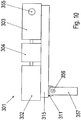
- FIG. 9 shows a detailed view of FIG. 1 ,
- An alignment means 8 for aligning the motor 2 relative to the support structure 5 is arranged on the motor support part 19.
- the alignment means 8 has a bolt 50, which is partially disposed in the recess 33 of the motor support part 19.
- the bolt has a step-like taper.
- a step touches the motor support part 19.
- the tapered region of the bolt 50 is inserted into the recess 33 and / or glued.
- the bolt is screw-connected to the recess 33, wherein the recess 33 is designed as a threaded bore.
- the tapered portion has a thread which is completely passed through the recess 33.
- the thread of the bolt 50 is screw-connected to a nut, not shown.
- the tapered portion of the bolt 50 has a through hole that passes completely through the recess 33.
- a split pin is inserted, by means of which the bolt 50 is detachably connected to the motor support part 19.
- the tapered portion of the bolt 50 has a circumferential groove which is completely passed through the recess 33.
- the bolt 50 can be detachably connected to the motor support part 19.
- the alignment means 28 is designed as a metal part, in particular made of stainless steel, preferably V2A stainless steel.
- the alignment means 28 made of semi-finished products, such as a hexagonal part, a square part or round steel, manufactured, in particular as a rotating part.
- a flat iron with a welded pin can be used, wherein the pin is inserted into the recess and the flat iron has a threaded bore for the screw 52.
- the bolt 50 has a threaded bore with which a screw 52 is screw-connected.
- the screw 52 contacts the motor 2.
- a nut 51 is arranged on the screw 52. By means of the nut 51, the screw 52 is lockable relative to the motor second
- the motor 2 is releasably connected to the motor support part 19 by means of at least one fastening element (17, 27).
- the foot part 9 of the motor at least one Recess on.
- the fastening element (17, 27) is guided through the recess in the foot part 9 and through the recess 32.
- the motor 2 is movable in the horizontal transverse direction to the rotor shaft axis direction.
- the motor 2 is movable in the vertical transverse direction.
- the drive package 1 has at least two opposing alignment means 28.
- the motor 2 is arranged in the transverse direction to the rotor shaft axis between the alignment means 28.
- the motor 2 can be pressed by means of a first alignment means 28 in a first horizontal transverse direction to the rotor shaft axis direction and can be pressed by means of a second alignment means 28 in a second horizontal transverse direction opposite the first horizontal transverse direction.
- the motor 2 When assembling the drive package 1, the motor 2 is moved relative to the support structure 5 to coaxially align the output shaft of the motor 2 and the input shaft of the transmission 3.
- the motor 2 by means of at least one fastening element (17, 27), which is guided through a recess in the foot portion 9 of the motor 2 and the recess 32 in the motor support member 19, finger-tightly connected to the support structure 5.
- the screw 52 is threaded through the threaded hole in the bolt 50 until the screw 52 contacts the foot 9 of the motor 2. Then, the screw member 52 is further screwed so that it presses against the motor 2 and shifts the motor 2 in the horizontal transverse direction to the rotor shaft axis direction. Once the motor 2 is aligned in the horizontal transverse direction, the screw 52 is countered by the nut 51 against the bolt 50. Then the fastening element (17, 27) is fixed.
- the alignment means 28 may be removed to be reused for another drive package or remain on the reorientation support structure.
- the recess 33 is closed by means of a cover part, not shown, in particular plastic cover part.
Landscapes
- Engineering & Computer Science (AREA)
- General Engineering & Computer Science (AREA)
- Mechanical Engineering (AREA)
- Connection Of Motors, Electrical Generators, Mechanical Devices, And The Like (AREA)
- General Details Of Gearings (AREA)
- Hybrid Electric Vehicles (AREA)
- Manufacture Of Motors, Generators (AREA)
Description
- Die Erfindung betrifft ein Antriebspaket.
- Aus der
DE 10 2008 058 521 B4 ist eine Baureihe von Antriebspaketen und ein Verfahren zur Herstellung von Antriebspaketen bekannt. - Die
DE 33 07 923 A1 zeigt eine Grundplatte für Maschinenaggregate. - In der
DE 10 2006 007 637 B3 sind ein Querträger und Baukastensystem für ein kombiniertes Transport- und Aufstellsystem eines Motors und ein Verfahren zum Transport und Aufstellen eines Motors mit diesem Querträger und Baukastensystem gezeigt. - Aus der
DE 10 2007 028 446 A1 sind ein Fundamentrahmen oder Motorschwinge für eine Getriebe-Motor-Einheit und ein Verfahren bekannt. - Die
GB 2 142 411 A - In der
DE 203 04 111 U1 ist ein Gestell zum Tragen einer Pumpeneinheit gezeigt. - Der Erfindung liegt daher die Aufgabe zugrunde, ein Antriebspaket weiterzubilden, wobei der Umweltschutz verbessert werden soll.
- Erfindungsgemäß wird die Aufgabe bei dem Antriebspaket nach den in Anspruch 1 angegebenen Merkmalen gelöst.
- Wichtige Merkmale der Erfindung bei dem Antriebspaket, aufweisend einen Motor mit einer Rotorwelle, ein Getriebe und eine Tragestruktur, sind, dass
die Tragestruktur ein Tragteil mit einem Getriebeauflageabschnitt und ein Motorauflageteil aufweist, wobei das Tragteil und der Getriebeauflageabschnitt einstückig ausgeführt sind,
wobei der Motor mittels des Motorauflageteils auf der Tragestruktur montiert ist, insbesondere wobei das Motorauflageteil zwischen dem Motor und dem Tragteil angeordnet ist,
wobei das Getriebe auf dem Getriebeauflageabschnitt aufgelagert ist und mittels des Getriebeauflageabschnitts mit der Tragestruktur verbunden ist,
wobei das Tragteil ein Blechteil ist,
wobei das Motorauflageteil ein Blechteil ist,
wobei das Tragteil sich in Rotorwellenachsrichtung weiter als in Querrichtung zur Rotorwellenachsrichtung erstreckt,
wobei das Motorauflageteil sich in der Querrichtung zur Rotorwellenachsrichtung weiter als in Rotorwellenachsrichtung erstreckt. - Von Vorteil ist dabei, dass die aus Blechteilen ausgeführte Tragestruktur kompakt und leicht ausführbar ist. Mittels des quer zur Rotorwellenachsrichtung angeordneten Motorauflageteils ist dabei die Verdrehsteifigkeit, Verwindungssteifigkeit und Schwingungsfestigkeit der Tragestruktur verbessert. Vorteilhafterweise liegt die Resonanzfrequenz der Tragestruktur außerhalb der üblichen Motor-Anregungsfrequenz.
- Blechteile zur Herstellung der Tragestruktur sind platzsparend lagerbar und in einem Arbeitsschnitt auf die spezifische Kombination von Motor und Getriebe zuschneidbar. Dabei sind insbesondere die Höhe der Rotorwelle des Motors und der eintreibenden Welle des Getriebes aufeinander anpassbar, indem das Tragteil verschiedene Höhen für das Motorauflageteil und den Getriebeauflageabschnitt aufweist.
- Vorteilhafterweise sind das Motorauflageteil und das Trageteil als Stanzteile oder Stanzbiegeteile in einfacher Art und Weise mit hoher Präzision herstellbar. Somit entfällt eine aufwändige Nachbearbeitung der Tragestruktur beispielsweise mittels Schleifen.
- Vorteilhafterweise ist das Schnittmuster für die Teile des Trageteils in einfacher Art und Weise übertragbar auf verschiedene Größen von Tragteilen oder verschiedene Blechmaterialien. Dabei ist eine hohe Prozesssicherheit ermöglicht, da das Schnittmuster eineindeutig übertragbar ist.
- Vorteilhafterweise sind alle Teile der Tragestruktur aus dem gleichen Blech herstellbar. Somit ist ein Antriebspaket für eine Anwendung bei extremen Außenbedingungen, die ein spezielles Material, insbesondere Stahllegierung, erforderlich machen, vollständig aus ebendiesem Material herstellbar.
- Von Vorteil ist dabei weiter, dass der Getriebeauflageabschnitt in einem Fertigungsschritt mit dem Tragteil fertigbar ist. Mittels des gewinkelt ausgeführten Getriebeauflageabschnitts ist die Verdrehsteifigkeit und Schwingungsfestigkeit der Tragestruktur weiter verbessert.
- Bei einer vorteilhaften Ausgestaltung weist die Tragestruktur ein Fußteil auf, wobei die Tragestruktur mittels des Fußteils aufgelagert ist, insbesondere auf einer Unterlage, insbesondere Boden, wobei das Motorauflageteil und das Fußteil gleichartig ausgeführt sind, insbesondere identisch. Von Vorteil ist dabei, dass die Tragestruktur mittels des Fußteils kippsicher auf der Unterlage anordenbar ist.
- Vorteilhafterweise ist durch die Wiederverwendbarkeit der Motorauflageteile als Fußteile ein Baukasten mit verringerter Teilezahl ermöglicht. Motorauflageteile und Fußteile sind kostengünstig vorhaltbar. Somit ist der Umweltschutz verbessert.
- Bei einer vorteilhaften Ausgestaltung erstreckt sich das Fußteil in der Querrichtung zur Rotorwellenachsrichtung weiter als in Rotorwellenachsrichtung. Von Vorteil ist dabei, dass mittels des Fußteils die Verdrehsteifigkeit und Schwingungsfestigkeit der Tragestruktur weiter verbessert ist.
- Bei einer vorteilhaften Ausgestaltung weisen das Motorauflageteil und das Fußteil jeweils eine erste Ausnehmung und eine zweite Ausnehmung auf, wobei der Motor mittels eines durch die erste Ausnehmung geführten Befestigungselementes mit der Tragestruktur verbindbar ist, insbesondere wobei die erste Ausnehmung als Langloch ausgeführt ist, insbesondere das sich in Rotorwellenachsrichtung weiter als in der Querrichtung zur Rotorwellenachsrichtung erstreckt, wobei die Tragestruktur mittels eines durch die zweite Ausnehmung geführten Befestigungselementes auf einer Unterlage, insbesondere Boden, montierbar ist. Von Vorteil ist dabei, dass mittels der ersten Ausnehmung der Axialabstand zwischen Motor und Kupplung veränderlich ist und das Kupplungsspiel einstellbar ist.
- Vorteilhafterweise sind die Ausnehmungen in einem Arbeitsschritt mit dem Motorauflageteil beziehungsweise dem Fußteil als Stanzteil fertigbar. Somit ist der Fertigungsaufwand reduzierbar und der Umweltschutz ist verbessert.
- Bei einer vorteilhaften Ausgestaltung ist/sind das Tragteil und/oder das Motorauflageteil und/oder das Fußteil als Biegeteil ausgeführt, insbesondere als Stanzbiegeteil, insbesondere als Winkelblechteil. Von Vorteil ist dabei, dass Biegeteile eine verbesserte Steifigkeit, insbesondere Verdrehsteifigkeit, aufweisen als ebene Blechteile. Die Blechteile sind dünner ausführbar und Material und Gewicht ist einsparbar. Somit ist der Umweltschutz verbessert.
- Bei einer vorteilhaften Ausgestaltung weist das Tragteil zwei Teilabschnitte auf, die in einem nichtverschwindenden Winkel zueinander angeordnet sind, insbesondere wobei dieser Winkel zwischen 90° und 180° beträgt, insbesondere zwischen 135° und 180°, insbesondere zwischen 150° und 170°, wobei zwischen diesen Teilabschnitten ein Kantungsabschnitt angeordnet ist, der sich in Rotorwellenachsrichtung vollständig durch das Tragteil erstreckt. Von Vorteil ist dabei, dass die Verdrehsteifigkeit der Tragestruktur weiter verbessert ist. Das Tragteil ist dünner ausführbar und der Umweltschutz ist verbessert.
- Bei einer vorteilhaften Ausgestaltung sind das Motorauflageteil und/oder das Fußteil formschlüssig und stoffschlüssig mit dem Tragteil verbunden, insbesondere schweißverbunden. Von Vorteil ist dabei, dass Schweißnähte zwischen dem Motorauflageteil beziehungsweise dem Fußteil und dem Tragteil kleiner ausführbar sind als bei einer ausschließlich stoffschlüssigen Verbindung. Somit ist Material einsparbar und die Tragestruktur ist leichter ausführbar.
- Bei einer vorteilhaften Ausgestaltung weist das Tragteil zumindest eine Positioniernut auf zur Verbindung mit dem Motorauflageteil oder dem Fußteil. Von Vorteil ist dabei, dass das Motorauflageteil beziehungsweise das Fußteil in einfacher Art und Weise positionierbar ist auf dem Tragteil. Fertigungsfehler sind vermeidbar.
- Vorteilhafterweise ist die Positioniernut in einem Fertigungsschritt mit dem Trageteil fertigbar, insbesondere schneidbar oder stanzbar.
- Bei einer vorteilhaften Ausgestaltung weist das Tragteil einen Trageabschnitt auf, insbesondere der sich von dem Motor zu dem Getriebe erstreckt, wobei der Getriebeauflageabschnitt in einem nichtverschwindenden Winkel zu dem Trageabschnitt angeordnet ist, insbesondere wobei der Getriebeauflageabschnitt im rechten Winkel zu dem Trageabschnitt angeordnet ist. Von Vorteil ist dabei, dass der Getriebeauflageabschnitt in einem Fertigungsschritt mit dem Tragteil fertigbar ist. Mittels des gewinkelt ausgeführten Getriebeauflageabschnitts ist die Verdrehsteifigkeit und Schwingungsfestigkeit der Tragestruktur weiter verbessert.
- Bei einer vorteilhaften Ausgestaltung erstreckt sich der Getriebeauflageabschnitt in Rotorwellenachsrichtung weiter als in der Querrichtung zur Rotorwellenachsrichtung. Von Vorteil ist dabei, dass die Verdrehsteifigkeit und Schwingungsfestigkeit der Tragestruktur weiter verbessert sind.
- Bei einer vorteilhaften Ausgestaltung weist das Tragteil einen Bodenabschnitt auf, wobei der Bodenabschnitt in einem nicht verschwindenden Winkel zu dem Trageabschnitt angeordnet ist, insbesondere wobei der Winkel zwischen dem Bodenabschnitt und dem Trageabschnitt größer oder gleich 90° ist, insbesondere zwischen 90° und 180°, insbesondere zwischen 90° und 135°, insbesondere zwischen 100° und 120°. Von Vorteil ist dabei, dass Verdrehsteifigkeit und Schwingungsfestigkeit der Tragestruktur weiter verbessert sind.
- Bei einer vorteilhaften Ausgestaltung ist der Bodenabschnitt zwischen zwei Trageabschnitten angeordnet, insbesondere wobei das Tragteil einen im Wesentlichen U-förmigen Querschnitt aufweist. Von Vorteil ist dabei, dass das Tragteil zwischen den Schenkeln des U hohl ausführbar ist, somit ist Gewicht einsparbar. Der Umweltschutz ist verbessert.
- Bei einer vorteilhaften Ausgestaltung ist eine Drehmomentstütze mittels einer Drehmomentstützplatte mit der Tragestruktur verbunden, wobei die Drehmomentstützplatte formschlüssig mit dem Tragteil verbunden ist, insbesondere verzapft ist, insbesondere formschlüssig und stoffschlüssig verbunden, wobei die Drehmomentstütze lösbar mit der Drehmomentstützplatte verbunden ist, insbesondere mittels einer Schraubverbindung. Von Vorteil ist dabei, dass das Antriebspaket mittels der Drehmomentstütze mit einer Applikation verbindbar ist. Dabei leitet die Drehmomentstütze ein auf das Antriebspaket wirkendes Drehmoment ab.
- Vorteilhafterweise ist die Drehmomentstützplatte stoffschlüssig und formschlüssig mit der Tragestruktur verbunden. Somit ist die Widerstandsfähigkeit der Drehmomentstützplatte gegen Querkräfte verbessert, da die formschlüssige Verbindung ein Abreißen der Drehmomentstützplatte von dem Tragteil erschwert.
- Bei einer vorteilhaften Ausgestaltung weist die Tragestruktur ein Blechteil auf, das zumindest teilweise zwischen zwei Getriebeauflageabschnitten angeordnet ist, wobei das Blechteil als Biegeteil ausgeführt ist. Von Vorteil ist dabei, dass mittels des Blechteils Verdrehsteifigkeit und Schwingungsfestigkeit der Tragestruktur weiter verbessert sind.
- Vorteilhafterweise weist das Blechteil quer zur Rotorwellenachsrichtung verlaufende Kantungsabschnitte auf.
- Bei einer vorteilhaften Ausgestaltung ist das Tragteil zweistückig ausgeführt, wobei zwei Hälften des Tragteils stoffschlüssig miteinander verbunden sind, insbesondere schweißverbunden, insbesondere wobei das Tragteil eine lineare Schweißnaht, insbesondere I-Naht, aufweist, insbesondere die sich in Rotorwellenachsrichtung erstreckt. Von Vorteil ist dabei, dass das Tragteil in einfacher Art und Weise biegbar und anschließend verschweißbar ist.
- Bei einer vorteilhaften Ausgestaltung ist die Schweißnaht unterbrochen mittels zumindest einer Ausnehmung, insbesondere einer sich in Rotorwellenachsrichtung weiter als in der Querrichtung zur Rotorwellenachsrichtung erstreckenden Ausnehmung. Von Vorteil ist dabei, dass Material einsparbar ist, somit ist das Gewicht der Tragestruktur reduzierbar.
- Vorteilhafterweise ist überflüssiges Material beim Pulverbeschichten oder Feuerverzinken mittels der Ausnehmung abführbar, so dass weiteres Material einsparbar ist.
- Bei einer vorteilhaften Ausgestaltung sind die zwei Hälften des Tragteils spiegelsymmetrisch zueinander ausgeführt. Von Vorteil ist dabei, dass die zwei Hälften des Tragteils gleichmäßig mit Gewichtskraft und Drehmoment beaufschlagbar sind.
- Vorteilhafterweise sind die zwei Hälften mit dem gleichen Stanzwerkzeug herstellbar. Somit sind Werkzeuge einsparbar und der Umweltschutz ist verbessert.
- Bei einer vorteilhaften Ausgestaltung weist das Antriebspaket eine Kupplung auf, insbesondere eine Fluidkupplung, wobei die Kupplung die Rotorwelle des Motors und eine eintreibende Welle des Getriebes miteinander verbindet, wobei die Tragestruktur eine Wanne aufweist, die den von der Kupplung in Rotorwellenachsrichtung überdeckten Bereich überdeckt. Von Vorteil ist dabei, dass aus der Kupplung austretendes Fluid mittels der Wanne auffangbar ist und nicht auf die Applikation spritzt oder tropft. Somit ist die Sicherheit verbessert.
- Bei einer vorteilhaften Ausgestaltung ist die Wanne stoffschlüssig mit dem Tragteil verbunden, insbesondere schweißverbunden. Von Vorteil ist dabei, dass die Wanne die Verdrehsteifigkeit und Schwingungsfestigkeit der Tragestruktur weiter verbessert.
- Bei einer vorteilhaften Ausgestaltung weist das Antriebspaket einen Lüfter auf, wobei der Lüfter in Rotorwellenachsrichtung zwischen der Kupplung und dem Getriebe angeordnet ist, wobei ein Lüfterrad des Lüfters drehfest mit der eintreibenden Welle des Getriebes verbunden ist. Von Vorteil ist dabei, dass das Getriebe kühlbar ist mittels des Lüfters. Dabei ist das Antriebspaket kompakt ausführbar. Ein zusätzlicher Lüftermotor ist einsparbar.
- Bei einer vorteilhaften Ausgestaltung weist die Tragestruktur Ausnehmungen auf, insbesondere Transportbohrungen, wobei die Ausnehmungen als gestanzte oder geschnittene Ausnehmungen ausgeführt sind. Von Vorteil ist dabei, dass die Ausnehmungen in einem Fertigungsschritt mit dem Tragteil stanzbar oder schneidbar sind.
- Bei einer vorteilhaften Ausgestaltung sind die Ausnehmungen als Transportösen oder zur Aufnahme von Zinken eines Gabelstaplers geeignet ausgeführt. Von Vorteil ist dabei, dass das Antriebspaket zum Transport mittels der Ausnehmungen fixierbar ist. Zusätzliche Transportösen oder nachträglich eingebrachte Ausschnitte sind einsparbar.
- Weitere Vorteile ergeben sich aus den Unteransprüchen. Die Erfindung ist nicht auf die Merkmalskombination der Ansprüche beschränkt. Für den Fachmann ergeben sich weitere sinnvolle Kombinationsmöglichkeiten von Ansprüchen und/oder einzelnen Anspruchsmerkmalen und/oder Merkmalen der Beschreibung und/oder der Figuren, insbesondere aus der Aufgabenstellung und/oder der sich durch Vergleich mit dem Stand der Technik stellenden Aufgabe.
- Die Erfindung wird nun anhand von Abbildungen näher erläutert:
- In der
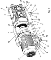
Figur 1 ist ein erstes Ausführungsbeispiel eines erfindungsgemäßen Antriebspaketes in Schrägansicht gezeichnet. -
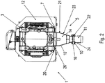
Figur 2 zeigt eine Seitenansicht des ersten Ausführungsbeispiels des erfindungsgemäßen Antriebspaketes. - In
Figur 3 ist eine Tragestruktur eines zweiten Ausführungsbeispiels des erfindungsgemäßen Antriebspaketes in Schrägansicht dargestellt. -
Figur 4 zeigt eine Draufsicht der Tragestruktur des zweiten Ausführungsbeispiels. - In
Figur 5 ist eine Seitenansicht der Tragestruktur des zweiten Ausführungsbeispiels gezeichnet. -
Figur 6 zeigt ein drittes Ausführungsbeispiel des erfindungsgemäßen Antriebspaketes in Schrägansicht. - In
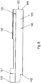
Figur 7 ist eine weitere Tragestruktur des dritten Ausführungsbeispiels des erfindungsgemäßen Antriebspaketes in Schrägansicht dargestellt. - In
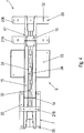
Figur 8 ist ein Tragteil der Tragestruktur des dritten Ausführungsbeispiels gezeichnet. -
Figur 9 zeigt eine Detailansicht vonFigur 1 . -
Figur 10 zeigt eine schematische Ansicht einer Auflagerung des ersten Ausführungsbeispiels des erfindungsgemäßen Antriebspaketes. - In den
Figuren 1 ,2 ,9 und10 ist das erste Ausführungsbeispiel des erfindungsgemäßen Antriebspaketes dargestellt. - In den
Figuren 3 ,4 und5 ist das zweite Ausführungsbeispiel des erfindungsgemäßen Antriebspaketes dargestellt. - In den
Figuren 6 ,7 und8 ist das dritte Ausführungsbeispiel des erfindungsgemäßen Antriebspaketes dargestellt. - Identische Teile im ersten, zweiten und dritten Ausführungsbeispiel sind mit identischen Bezugszeichen bezeichnet.
- Das in der
Figur 1 und2 dargestellte Antriebspaket 1 weist einen Motor 2, ein Getriebe 3 und eine Tragestruktur 5 auf. Es ist als Motorschwinge ausgeführt. - Der Motor 2 weist eine Rotorwelle auf. Die Rotorwelle definiert eine Rotorwellenachsrichtung. Eine Querrichtung zur Rotorwellenachsrichtung ist definiert als die horizontale Querrichtung, insbesondere die quer zur Gewichtskraft des Antriebspaketes sich erstreckt.
- Die Tragestruktur 5 weist ein Tragteil 15 mit zwei Getriebeauflageabschnitten (7, 20) und zwei Motorauflageteile (6, 19) auf.
- Auf den Getriebeauflageabschnitten (7, 20) ist das Getriebe 3 montiert. Dazu weisen die Getriebeauflageabschnitte (7, 20) jeweils zumindest eine Ausnehmung 25 auf. Vorzugsweise wird die Ausnehmung 25 in einem Arbeitsgang mit dem Tragteil 15 gestanzt oder lasergeschnitten oder autogen geschnitten oder plasmageschnitten.
- Das Getriebe 3 ist mittels eines Befestigungselementes 8, insbesondere Schraubmittel, das durch eine Bohrung im Gehäuse des Getriebes 3 und die Ausnehmung 25 geführt ist, mit dem jeweiligen Getriebeauflageabschnitt (7, 20) lösbar verbunden.
- Auf den Motorauflageteilen (6, 19) ist der Motor 2 montiert. Dazu weisen die Motorauflageteile (6, 19) jeweils zumindest eine Ausnehmung 32, vorzugsweise Langloch, auf, das in einem Arbeitsgang mit dem jeweiligen Motorauflageteil (6, 19) gestanzt oder lasergeschnitten wird. Das Langloch erstreckt sich in Rotorwellenachsrichtung weiter als in Querrichtung zur Rotorwellenachsrichtung.
- Die Motorauflageteile (6, 19) erstrecken sich in Querrichtung zur Rotorwellenachsrichtung weiter als das Tragteil 15. Vorzugsweise weist jedes Motorauflageteil (6, 19) zwei Ausnehmungen 32 auf, wobei das Tragteil 15 in dieser Querrichtung zur Rotorwellenachsrichtung zwischen den Ausnehmungen 32 angeordnet ist.
- Der Motor 2 ist mittels eines Befestigungselementes 17, 27, insbesondere Schraubmittel, das durch eine Bohrung in einem Fußteil 9 des Motors 2 und durch die Ausnehmung 32 geführt ist, mit dem jeweiligen Motorauflageteil (6, 19) lösbar verbunden.
- Zwischen dem Fußteil 9 des Motors 2 und den Motorauflageteilen (6, 19) sind Zwischenbleche anordenbar zur Ausrichtung des Motors in vertikaler Richtung. Die Blechstärke der Zwischenbleche beträgt 1 mm bis 5 mm.
- Das Tragteil 15 ist als Blechteil ausgeführt. Vorteilhafterweise ist das Tragteil 15 als Stanzbiegeblechteil ausgeführt oder mittels eines Schneidverfahrens, insbesondere mittels eines Laserschneidverfahrens hergestellt. Vorzugsweise ist das Tragteil 15 in einem Arbeitsgang mit Nuten und Ausnehmungen im Tragteil 15 hergestellt.
- Das Tragteil 15 weist die Getriebeauflageabschnitte (7, 20), zwei Trageabschnitte 23 und einen Bodenabschnitt 24 auf. Vorzugsweise verbindet der Bodenabschnitt 24 die zwei Trageabschnitte 23. Vorzugsweise weist das Tragteil 15 einen im Wesentlichen U-förmigen Querschnitt auf.
- Der Bodenabschnitt 24 ist in einem nichtverschwindenden Winkel zu dem jeweiligen Trageabschnitt 23 angeordnet. Vorzugsweise ist der Winkel zwischen dem Bodenabschnitt 24 und dem jeweiligen Trageabschnitt 23 größer oder gleich 90°, insbesondere zwischen 90° und 180° groß, insbesondere zwischen 90° und 135° groß, insbesondere zwischen 100° und 120° groß. Der Bodenabschnitt 24 ist gekantet relativ zum Trageabschnitt 23 angeordnet. Zwischen dem Bodenabschnitt 24 und dem Trageabschnitt 23 ist ein Kantungsabschnitt 22 angeordnet, der sich in Rotorwellenachsrichtung erstreckt.
- Die Trageabschnitte 23 weisen jeweils einen Kantungsabschnitt 21 auf, der sich in Rotorwellenachsrichtung durch das gesamte Tragteil 15 erstreckt. Zwei Teilabschnitte jedes Trageabschnittes 23, die mittels des Kantungsabschnittes 21 miteinander verbunden sind, sind also in einem nichtverschwindenden Winkel zueinander angeordnet. Dieser Winkel beträgt zwischen 90° und 180°, insbesondere zwischen 135° und 180°, insbesondere zwischen 150° und 170°.
- Die Höhe der Trageabschnitte 23 ist abhängig von der Größe des Motors 2 und des Getriebes 3 im Axialbereich der Motorauflageteile (6, 19) größer, kleiner oder gleich wie im Axialbereich der Getriebeauflageabschnitte (7, 20). Dabei ist die Höhe der Trageabschnitte 23 bei der Herstellung mittels Stanzens oder Schneidens an jede Kombination von Motor 2 und Getriebe 3 stufenlos anpassbar. Die Blechstärke der Tragestruktur 5 ist an Größe und Gewicht des Motors 2 und Getriebes 3 anpassbar.
- Das Tragteil 15 ist zweistückig ausgeführt, wobei die zwei Hälften des Tragteils 15 spiegelsymmetrisch zueinander ausgeführt sind und mittels Schweißens miteinander verbunden sind, insbesondere mittels einer linearen Schweißnaht 30, insbesondere I-Naht. Die zwei Hälften des Tragteils 15 sind mittels eines linienhaften Verbindungsabschnitts miteinander verbunden. Dabei erstreckt sich der Verbindungsabschnitt in Rotorwellenachsrichtung. Vorzugsweise weist das Tragteil 15 entlang des Verbindungsabschnitts der zwei Hälften Ausnehmungen auf, insbesondere wobei die Schweißnaht 30 unterbrochen ist von den Ausnehmungen.
- Zwischen den zwei Trageabschnitten 23 des Tragteils 15 ist ein Blechteil 14 angeordnet. Das Blechteil 14 ist als Biegeteil ausgeführt, vorzugsweise weist das Blechteil 14 drei Teilabschnitte auf, die jeweils in einem nichtverschwindenden Winkel, vorzugsweise im rechten Winkel, zueinander angeordnet sind. Die Teilabschnitte spannen jeweils eine Ebene auf, wobei zwei Ebenen die dritte Ebene schneiden. Die Schnittgeraden der Ebenen erstrecken sich in Querrichtung zur Rotorwellenachsrichtung. Das Blechteil 14 ist mit dem Tragteil 15 stoffschlüssig verbunden, insbesondere schweißverbunden.
- Die Tragestruktur 5 weist eine Drehmomentstütze 11 auf. Die Drehmomentstütze 11 ist mittels einer Drehmomentstützplatte 16 mit dem Bodenabschnitt 24 des Tragteils 15 verbunden. Vorzugsweise ist die Drehmomentstütze 11 mittels eines Befestigungselementes 10, insbesondere Schraubteils, lösbar mit der Drehmomentstützplatte 16 verbunden.
- Die Drehmomentstützplatte 16 ist mit dem Bodenabschnitt 24 des Tragteils 15 formschlüssig mittels zumindest eines Zapfens verbunden und stoffschlüssig mittels einer Schweißverbindung verbunden. Vorzugsweise weist die Drehmomentstützplatte 16 zumindest einen Zapfen auf, der in einer Ausnehmung in dem Bodenabschnitt 24 aufgenommen ist, insbesondere vollständig aufgenommen.
- Die Drehmomentstütze 11 weist eine durchgehende Ausnehmung auf, die sich in Querrichtung zur Rotorwellenachsrichtung erstreckt.
- Die Drehmomentstütze 11 erstreckt sich in Querrichtung zur Rotorwellenachsrichtung weiter als der Bodenabschnitt 24. Vorzugsweise erstreckt sich die Drehmomentstütze 11 in Querrichtung zur Rotorwellenachsrichtung gleich weit wie der Bodenabschnitt 24. Die Drehmomentstützplatte 16 erstreckt sich in Querrichtung zur Rotorwellenachsrichtung weiter als die Drehmomentstütze 11.
- Wie in
Figur 10 schematisch dargestellt, ist das Tragteil 315 mittels der Drehmomentstütze 311 auf einem Träger 357, insbesondere einem Stahlträger, aufgelagert. Dazu weist der Träger 357 eine Ausnehmung, insbesondere eine durchgehende Ausnehmung, auf, in die ein Bolzen 356 eingeführt ist. Der Bolzen 356 verbindet die Drehmomentstütze 311 mit dem Träger 357, indem der Bolzen 356 in die Ausnehmung in dem Träger 357 eingeführt ist, insbesondere sich durch diese Ausnehmung hindurch erstreckt. Vorzugsweise ist der Bolzen 356 mit dem Träger 357 und der Drehmomentstütze 311 stoffschlüssig verbunden, insbesondere schweißverbunden. - Vorzugsweise ist der Träger 357 mit einem nicht dargestellten Fundament und/oder einer nicht dargestellten von der Antriebseinheit anzutreibenden Applikation verbunden.
- Das erste Ausführungsbeispiel des Antriebspaketes 301 ist mittels einer abtreibenden Welle 355 des Getriebes mit einer nicht dargestellten anzutreibenden Applikation verbunden. Vorzugsweise erstreckt sich die Drehachse der abtreibenden Welle quer zur Rotorwellenachse.
- Im Ruhezustand des Antriebspaketes 301 verteilt sich die Gewichtskraft des Antriebspaketes 301 gleichmäßig auf den mittels der Drehmomentstütze 311 mit dem Antriebspaket 301 verbundenen Träger 357 und auf die mittels der abtreibenden Welle 355 mit dem Antriebspaket 301 verbundene Applikation.
- Im Betriebszustand des Antriebspaketes 301 ändert sich die Lastverteilung in Abhängigkeit von der Drehrichtung und Drehgeschwindigkeit der abtreibenden Welle 355. Dadurch wirken entweder Druckkräfte oder Zugkräfte auf die Drehmomentstütze 311 oder es stellt sich ein Gleichgewicht zwischen der Gewichtskraft und der aus dem Drehmoment des Antriebspaketes 301 resultierenden Kraft ein.
- In einem nicht dargestellten Ausführungsbeispiel weist das Getriebe 303 einen Flansch auf, insbesondere einen die abtreibende Welle 355 in Umfangsrichtung der abtreibenden Welle 355 umgebenden Flansch. Mittels des Flansches ist das Getriebe 303, und somit das Antriebspaket 301, mit einer Applikation verbindbar, so dass die Gewichtskraft des Antriebspaketes 301 sich im Ruhezustand des Antriebspaketes 301 gleichmäßig auf den Träger 357 und die mittels des Flansches mit dem Antriebspaket 301 verbundene Applikation verteilt.
- Die Getriebeauflageabschnitte (7, 20) sind einstückig mit dem Tragteil 15 ausgeführt. Der jeweilige Getriebeauflageabschnitt (7, 20) ist in einem nichtverschwindenden Winkel, vorzugsweise einem rechten Winkel, zu dem jeweiligen Trageabschnitt 23 des Tragteils 15 angeordnet. Vorzugsweise sind die Getriebeauflageabschnitte (7, 20) mittels Biegen hergestellt.
- Die Motorauflageteile (6, 19) sind als Blechteile, insbesondere Stanzbiegeteile ausgeführt. Vorzugsweise sind die Motorauflageteile (6, 19) als Winkelteile oder Winkelblechteile ausgeführt, insbesondere rechtwinkelige Winkelteile. Vorzugsweise weist jedes Motorauflageteil (6, 19) zwei Motorauflageteilabschnitte auf, die in einem Winkel zwischen 45° und 135°, vorzugsweise im rechten Winkel, zueinander angeordnet sind.
- Das Tragteil 15 weist zumindest eine Positioniernut 41 und zumindest eine Ausrichtnut 40 zur Aufnahme der Motorauflageteile (6, 19) auf. Dabei erstreckt sich die Positioniernut 41 tiefer in das Tragteil 15 hinein als die Ausrichtnut 40.
- Ein Motorauflageteil 19 ist in der Positioniernut 41 angeordnet. Vorzugsweise ist ein Motorauflageteilabschnitt dieses Motorauflageteils 19 von der Positioniernut 41 aufgenommen, insbesondere vollständig aufgenommen.
- Ein Motorauflageteil 6 liegt auf dem Tragteil 15 auf und ist an der Ausrichtnut 40 ausgerichtet. Vorzugsweise berührt ein Seitenabschnitt dieses Motorauflageteils 6 die Ausrichtnut 40.
- Die Motorauflageteile (6, 19) sind mit dem Tragteil 15 formschlüssig verbunden mittels der Positioniernut 41 beziehungsweise der Ausrichtnut 40 und stoffschlüssig verbunden, vorzugsweise verschweißt, vorzugsweise mittels einer linearen Schweißnaht, insbesondere I-Naht.
- Auf der dem Getriebeauflageabschnitt (7, 20) gegenüberliegenden Seite weist das Tragteil 15 zumindest eine weitere Positioniernut 43 auf. Vorzugsweise grenzt die weitere Positioniernut 43 an den Bodenabschnitt 24 an.
- Mittels der weiteren Positioniernut 43 ist ein Transportblechteil 18 positionierbar. Vorzugsweise ist das Transportblechteil 18 baugleich zu dem Motorauflageteil (6, 19) ausgeführt. Das Transportblechteil 18 ist zumindest teilweise in die weitere Positioniernut 43 eingeführt und formschlüssig mit dem Tragteil 15 verbunden mittels der weiteren Positioniernut 43 und kraftschlüssig mit dem Tragteil 15 verbunden, vorzugsweise mittels einer lösbaren Verbindung, insbesondere Schraubverbindung. Das Transportblechteil 18 erstreckt sich in Querrichtung zur Rotorwellenachsrichtung weiter als der Bodenabschnitt 24.
- Das Transportblechteil 18 weist eine Ausnehmung 33 auf, mittels der das Antriebspaket beim Transport auf einer Transportvorrichtung, insbesondere Transportpalette, mit der Transportvorrichtung lösbar verbindbar ist. Vorzugsweise ist das Transportblechteil 18 mittels eines durch die Ausnehmung 33 geführten Schraubmittels mit der Transportvorrichtung verbindbar.
- Das Transportblechteil 18 weist eine weitere Ausnehmung 34 auf, die sich parallel zur Rotorwellenachsrichtung durch das Transportblechteil 18 hindurch erstreckt. Dabei ist die weitere Ausnehmung 34 quer zur Ausnehmung 33 ausgerichtet. Mittels der weiteren Ausnehmung 34 ist ein Kran, insbesondere Kranhaken, mit dem Antriebspaket verbindbar zum Transport des Antriebspaketes.
- Das Transportblechteil 18 erstreckt sich in Querrichtung zur Rotorwellenachsrichtung weiter als das Tragteil 15. Vorzugsweise weist das Transportblechteil 18 zwei Ausnehmungen 33 auf, wobei das Tragteil 15 in Querrichtung zur Rotorwellenachsrichtung zwischen den zwei Ausnehmungen 33 angeordnet ist.
- Ein als Motorauflageteil (6, 19) oder Transportblechteil 18 verwendbares Blechteil weist also zwei Ausnehmungen (32, 33) auf, insbesondere wobei eine Ausnehmung als Langloch ausgeführt ist. Vorzugsweise weist das Blechteil zwei Paare von Ausnehmungen (32, 33) auf, wobei das Tragteil in Querrichtung zur Rotorwellenachsrichtung zwischen den Paaren von Ausnehmungen (32, 33) angeordnet ist.
- Die Rotorwelle des Motors 2 und eine eintreibende Welle des Getriebes 3 sind mittels einer Kupplung 4 miteinander verbunden. Vorzugsweise ist die Kupplung 4 als Turbokupplung oder Fluidkupplung ausgeführt.
- Auf dem Tragteil 15 ist eine Wanne 13 angeordnet, die mit dem Tragteil 15 verbunden, insbesondere schweißverbunden, ist. Die Wanne 13 ist unterhalb der Kupplung 4 angeordnet. Mittels der Wanne 13 ist aus der Kupplung 4 austretendes Fluid auffangbar.
- Die Kupplung 4 ist mittels einer Haube 12 abgedeckt. Die Haube 12 fungiert als Berührschutz für die Kupplung 4.
- In Rotorwellenachsrichtung zwischen der Kupplung 4 und dem Getriebe 3 ist ein Lüfter 29 angeordnet zur Kühlung des Getriebes. Das Lüfterrad des Lüfters 29 ist drehfest mit der eintreibenden Welle des Getriebes 3 gekoppelt.
- Das in den
Figuren 3 bis 5 dargestellte zweite Ausführungsbeispiel des Antriebspaketes unterscheidet sich von dem ersten Ausführungsbeispiel dadurch, dass die Motorauflageteile (206, 219) und das Transportblechteil 218 als flache Blechteile ausgeführt sind, also ungewinkelt. - Die Motorauflageteile (206, 219) liegen auf dem Tragteil 15 auf und sind mit diesem stoffschlüssig verbunden, vorzugsweise schweißverbunden. Das Transportblechteil 218 liegt auf dem Tragteil 15 auf und ist lösbar mit dem Tragteil 15 verbunden, vorzugsweise mittels eines Schraubteils.
- Die Motorauflageteile (206, 219) und das Transportblechteil 218 weisen jeweils zwei Ausnehmungen (32, 33, 153, 154) auf. Dabei ist eine Ausnehmung 32 zur Montage des Motors 2 geeignet und vorzugsweise als Langloch ausgeführt. Eine Ausnehmung 154 ist zur Verbindung des Antriebspaketes mit einer Transportvorrichtung, insbesondere Transportpalette geeignet.
- Das in den
Figuren 6 bis 8 dargestellte dritte Ausführungsbeispiel des Antriebspaketes 101 weist anstatt der Drehmomentstütze 11 zumindest zwei Fußteile (150, 151, 152) auf. Es ist als Fundamentrahmen ausgeführt. - Das Antriebspaket 101 weist eine Tragestruktur 105 auf, die ein Tragteil 115 mit zwei Getriebeauflageabschnitten (107, 120) und zwei Motorauflageteilen (6, 19) aufweist.
- Das Tragteil 115 ist in vertikaler Richtung zwischen den Motorauflageteilen (6, 19) und den Fußteilen (150, 151, 152) angeordnet. Die Gewichtskraft des Motors 2 wird mittels des Tragteils 115 von den Motorauflageteilen (6, 19) zu den Fußteilen (150, 151, 152) geleitet. Die Fußteile (150, 151, 152) sind gleichartig mit den Motorauflageteilen (6, 19) ausgeführt. Die Fußteile (150, 151, 152) erstrecken sich in Querrichtung zur Rotorwellenachsrichtung weiter als der Bodenabschnitt.
- Mittels einer jeweiligen Ausnehmung in den Fußteilen (150, 151, 152) ist die Tragstruktur 5 auf einer Unterlage fixierbar. Dazu ist jeweils ein Schraubmittel durch die jeweilige Ausnehmung geführt und mit der Unterlage schraubverbunden.
- Das Tragteil 115 ist als Blechteil ausgeführt. Vorteilhafterweise ist das Tragteil 115 als Stanzbiegeblechteil ausgeführt oder mittels eines Schneidverfahrens, insbesondere mittels eines Laserschneidverfahrens hergestellt. Das Tragteil 115 weist die Getriebeauflageabschnitte (107, 120), zwei Trageabschnitte 123 und einen Bodenabschnitt 124 auf. Vorzugsweise verbindet der Bodenabschnitt 124 die zwei Trageabschnitte 123.
- Der Bodenabschnitt 124 ist in einem nichtverschwindenden Winkel zu dem jeweiligen Trageabschnitt 123 angeordnet. Vorzugsweise ist der Winkel zwischen dem Bodenabschnitt 124 und dem jeweiligen Trageabschnitt 123 größer oder gleich 90°, insbesondere zwischen 90° und 180° groß, insbesondere zwischen 90° und 135° groß, insbesondere zwischen 100° und 120° groß. Der Bodenabschnitt 124 ist gekantet relativ zum Trageabschnitt 23 angeordnet. Zwischen dem Bodenabschnitt 124 und dem Trageabschnitt 123 ist ein Kantungsabschnitt 122 angeordnet.
- Die Trageabschnitte 123 weisen jeweils einen Kantungsabschnitt 121 auf, der sich in Rotorwellenachsrichtung durch das gesamte Tragteil 115 erstreckt. Zwei Teilabschnitte jedes Trageabschnittes 123, die mittels des Kantungsabschnittes 121 miteinander verbunden sind, sind also in einem nichtverschwindenden Winkel zueinander angeordnet. Dieser Winkel beträgt zwischen 90° und 180°, insbesondere zwischen 135° und 180°, insbesondere zwischen 150° und 170°.
- Das Tragteil 115 ist zweistückig ausgeführt, wobei die zwei Hälften des Tragteils 115 spiegelsymmetrisch zueinander ausgeführt sind und mittels Schweißens miteinander verbunden sind, insbesondere mittels einer linearen Schweißnaht, insbesondere I-Naht. Die zwei Hälften des Tragteils 115 sind mittels eines linienhaften Verbindungsabschnitts miteinander verbunden. Dabei erstreckt sich der Verbindungsabschnitt in Rotorwellenachsrichtung. Vorzugsweise weist das Tragteil 115 entlang des Verbindungsabschnitts der zwei Hälften Ausnehmungen auf, insbesondere wobei die Schweißnaht unterbrochen ist von den Ausnehmungen.
- Zwischen den zwei Trageabschnitten 123 des Tragteils 115 ist ein Blechteil 114 angeordnet. Das Blechteil 114 ist als Biegeteil ausgeführt, vorzugsweise weist das Blechteil 114 drei Teilabschnitte auf, die jeweils in einem nichtverschwindenden Winkel, vorzugsweise im rechten Winkel, zueinander angeordnet sind. Die Teilabschnitte spannen jeweils eine Ebene auf, wobei zwei Ebenen die dritte Ebene schneiden. Die Schnittgeraden der Ebenen erstrecken sich in Querrichtung zur Rotorwellenachsrichtung.
- Die Getriebeauflageabschnitte (107, 120) sind einstückig mit dem Tragteil 115 ausgeführt. Der jeweilige Getriebeauflageabschnitt (107, 120) ist in einem nichtverschwindenden Winkel, vorzugsweise einem rechten Winkel, zu dem jeweiligen Trageabschnitt 123 des Tragteil 115 angeordnet. Vorzugsweise sind die Getriebeauflageabschnitte (107, 120) mittels Biegen hergestellt.
- Das Tragteil 115 weist zumindest eine Positioniernut 141 und zumindest eine Ausrichtnut 140 zur Aufnahme der Motorauflageteile (6, 19) auf. Dabei erstreckt sich die Positioniernut 141 tiefer in das Tragteil 115 hinein als die Ausrichtnut 140.
- Ein Motorauflageteil 19 ist in der Positioniernut 141 angeordnet. Vorzugsweise ist ein Motorauflageteilabschnitt dieses Motorauflageteils 19 von der Positioniernut 141 aufgenommen, insbesondere vollständig aufgenommen.
- Ein Motorauflageteil 6 liegt auf dem Tragteil 115 auf und ist an der Ausrichtnut 140 ausgerichtet. Vorzugsweise berührt ein Seitenabschnitt dieses Motorauflageteils 6 die Ausrichtnut 140.
- Die Motorauflageteile (6, 19) sind mit dem Tragteil 115 verschweißt, vorzugsweise mittels einer linearen Schweißnaht, insbesondere I-Naht.
- Auf der dem Getriebeauflageabschnitt (107, 120) gegenüberliegenden Seite weist das Tragteil 115 zumindest eine weitere Positioniernut 143 auf. Vorzugsweise grenzt die weitere Positioniernut 143 an den Bodenabschnitt 124 an.
- Mittels der Positioniernut 143 ist ein Fußteil 151 positionierbar. Das Fußteil 151 ist zumindest teilweise in die Positioniernut 143 eingeführt und fest mit dem Tragteil 15 verbunden, insbesondere schweißverbunden. Das Fußteil 151 erstreckt sich in Querrichtung zur Rotorwellenachsrichtung weiter als der Bodenabschnitt 124.
- Auf der dem Motorauflageteil (6, 19) gegenüberliegenden Seite weist das Tragteil 115 eine Ausrichtnut 142 auf. Vorzugsweise grenzt die Ausrichtnut 142 an den Bodenabschnitt 124 an. Mittels der Ausrichtnut 142 ist ein Fußteil 150 ausrichtbar relativ zum Tragteil 115. Vorzugsweise berührt das Fußteil 150 die Ausrichtnut 142.
- Auf der dem Getriebeauflageabschnitt (107, 120) gegenüberliegenden Seite weist das Tragteil 115 eine Ausrichtnut 144 auf. Vorzugsweise grenzt die Ausrichtnut 144 an den Bodenabschnitt 124 an. Mittels der Ausrichtnut 144 ist ein Fußteil 152 ausrichtbar relativ zum Tragteil 115. Vorzugsweise berührt das Fußteil 152 die Ausrichtnut 144.
- Bei einem weiteren nicht dargestellten Ausführungsbeispiel weist das Tragteil (15, 115) weitere Ausnehmungen auf, die in einem Arbeitsschritt mit dem Tragteil hergestellt werden. Diese weiteren Ausnehmungen sind beispielsweise als Aufnahmen für Zinken eines Gabelstaplers oder als Transportösen verwendbar.
- Bei einem weiteren nicht dargestellten Ausführungsbeispiel weist die Tragestruktur (5, 105) eine korrosionsbeständige Beschichtung auf. Vorzugsweise ist die Tragestruktur (5, 105) feuerverzinkt oder pulverbeschichtet ausgeführt.
- Alternativ sind die Fußteile und die Motorauflageteile des dritten Ausführungsbeispiels wie die Motorauflageteile (206, 219) des zweiten Ausführungsbeispiels als flache Blechteile ausgeführt.
-
Figur 9 zeigt eine Detailansicht derFigur 1 . Ein Ausrichtmittel 8 zum Ausrichten des Motors 2 relativ zur Tragestruktur 5 ist auf dem Motorauflageteil 19 angeordnet. Das Ausrichtmittel 8 weist einen Bolzen 50 auf, der teilweise in der Ausnehmung 33 des Motorauflageteils 19 angeordnet ist. - Der Bolzen weist eine stufenartige Verjüngung auf. Dabei berührt eine Stufe das Motorauflageteil 19. Der verjüngte Bereich des Bolzens 50 ist in die Ausnehmung 33 gesteckt und/oder geklebt. Alternativ ist der Bolzen mit der Ausnehmung 33 schraubverbunden, wobei die Ausnehmung 33 als Gewindebohrung ausgeführt ist.
- Alternativ weist der verjüngte Bereich ein Gewinde auf, das vollständig durch die Ausnehmung 33 hindurchgeführt ist. Mittels des Gewindes ist der Bolzen 50 mit einer nicht dargestellten Mutter schraubverbunden.
- Alternativ weist der verjüngte Bereich des Bolzens 50 eine durchgehende Bohrung auf, die vollständig durch die Ausnehmung 33 hindurchgeführt ist. In die Bohrung ist ein Splint einführbar, mittels dessen der Bolzen 50 lösbar mit dem Motorauflageteil 19 verbindbar ist.
- Alternativ weist der verjüngte Bereich des Bolzens 50 eine umlaufende Nut auf, die vollständig durch die Ausnehmung 33 hindurchgeführt ist. Mittels eines nicht dargestellten Sicherungsringes ist der Bolzen 50 lösbar mit dem Motorauflageteil 19 verbindbar.
- Das Ausrichtmittel 28 ist als Metallteil ausgeführt, insbesondere aus rostfreiem Edelstahl, vorzugsweise V2A Edelstahl. Vorzugsweise ist das Ausrichtmittel 28 aus Halbzeugen, wie zum Beispiel aus einem Sechskantteil, einem Vierkantteil oder aus Rundstahl, hergestellt, insbesondere als Drehteil.
- Alternativ ist statt des Bolzens 50 ein Flacheisen mit einem angeschweißten Zapfen verwendbar, wobei der Zapfen in die Ausnehmung eingeführt wird und das Flacheisen eine Gewindebohrung für das Schraubteil 52 aufweist.
- Der Bolzen 50 weist eine Gewindebohrung auf, mit der ein Schraubteil 52 schraubverbunden ist. Das Schraubteil 52 berührt den Motor 2. Auf dem Schraubteil 52 ist eine Mutter 51 angeordnet. Mittels der Mutter 51 ist das Schraubteil 52 konterbar relativ zum Motor 2.
- Der Motor 2 ist mittels zumindest eines Befestigungselementes (17, 27) mit dem Motorauflageteil 19 lösbar verbunden. Dazu weist das Fußteil 9 des Motors zumindest eine Ausnehmung auf. Das Befestigungselement (17, 27) ist durch die Ausnehmung im Fußteil 9 und durch die Ausnehmung 32 geführt.
- Mittels des Schraubteils 52 ist der Motor 2 bewegbar in horizontaler Querrichtung zur Rotorwellenachsrichtung.
- Mittels des nicht dargestellten Zwischenbleches ist der Motor 2 bewegbar in vertikaler Querrichtung.
- Vorzugsweise weist das Antriebspaket 1 zumindest zwei gegenüberliegende Ausrichtmittel 28 auf. Dabei ist der Motor 2 in Querrichtung zur Rotorwellenachsrichtung zwischen den Ausrichtmitteln 28 angeordnet. Somit ist der Motor 2 mittels eines ersten Ausrichtmittels 28 in einer ersten horizontalen Querrichtung zur Rotorwellenachsrichtung drückbar und mittels eines zweiten Ausrichtmittels 28 in einer der ersten horizontalen Querrichtung entgegengesetzten zweiten horizontalen Querrichtung drückbar.
- Bei der Montage des Antriebspaketes 1 wird der Motor 2 relativ zur Tragestruktur 5 bewegt, um die Abtriebswelle des Motors 2 und die eintreibende Welle des Getriebes 3 koaxial auszurichten. Dazu wird der Motor 2 mittels zumindest eines Befestigungselementes (17, 27), das durch eine Ausnehmung im Fußabschnitt 9 des Motors 2 und die Ausnehmung 32 im Motorauflageteil 19 geführt wird, fingerfest mit der Tragestruktur 5 verbunden. Das Schraubteil 52 wird durch die Gewindebohrung im Bolzen 50 geschraubt, bis das Schraubteil 52 das Fußteil 9 des Motors 2 berührt. Dann wird das Schraubteil 52 weiter geschraubt, so dass es gegen den Motor 2 drückt und den Motor 2 in horizontaler Querrichtung zur Rotorwellenachsrichtung verschiebt. Sobald der Motor 2 in horizontaler Querrichtung ausgerichtet ist, wird das Schraubteil 52 mittels der Mutter 51 gegen den Bolzen 50 gekontert. Dann wird das Befestigungselement (17, 27) fixiert.
- Danach kann das Ausrichtmittel 28 entfernt werden, um für ein weiteres Antriebspaket wiederverwendet zu werden, oder auf der Tragestruktur für eine erneute Ausrichtung verbleiben.
- Die Ausnehmung 33 ist mittels eines nicht dargestellten Deckelteils, insbesondere Kunststoffdeckelteils, verschließbar.
-
- 1
- Antriebspaket
- 2
- Motor
- 3
- Getriebe
- 4
- Kupplung
- 5
- Tragestruktur
- 6
- Motorauflageteil
- 7
- Getriebeauflageabschnitt
- 8
- Ausrichtmittel
- 9
- Fußabschnitt
- 10
- Befestigungselement
- 11
- Drehmomentstütze
- 12
- Haube
- 13
- Wanne
- 14
- Blechteil
- 15
- Tragteil
- 16
- Drehmomentstützplatte
- 17
- Befestigungselement
- 18
- Transportblechteil
- 19
- Motorauflageteil
- 20
- Getriebeauflageabschnitt
- 21
- Kantungsabschnitt
- 22
- Kantungsabschnitt
- 23
- Trageabschnitt
- 24
- Bodenabschnitt
- 25
- Ausnehmung
- 26
- Befestigungselement
- 27
- Befestigungselement
- 28
- Ausrichtmittel
- 29
- Lüfter
- 30
- Schweißnaht
- 31
- Ausnehmung
- 32
- Ausnehmung, insbesondere Langloch
- 33
- Ausnehmung, insbesondere Langloch
- 34
- Ausnehmung
- 40
- Ausrichtnut
- 41
- Positioniernut
- 43
- Positioniernut
- 50
- Bolzen
- 51
- Mutter
- 52
- Schraubteil
- 101
- Antriebspaket
- 105
- Tragestruktur
- 106
- Motorauflageteil
- 107
- Getriebeauflageabschnitt
- 115
- Tragteil
- 119
- Motorauflageteil
- 120
- Getriebeauflageabschnitt
- 121
- Kantungsabschnitt
- 122
- Kantungsabschnitt
- 123
- Trageabschnitt
- 124
- Bodenabschnitt
- 140
- Ausrichtnut
- 141
- Positioniernut
- 142
- Ausrichtnut
- 143
- Positioniernut
- 144
- Ausrichtnut
- 150
- Fußteil
- 151
- Fußteil
- 152
- Fußteil
- 153
- Ausnehmung
- 154
- Ausnehmung, insbesondere Langloch
- 206
- Motorauflageteil
- 218
- Transportblechteil
- 219
- Motorauflageteil
- 301
- Antriebspaket
- 302
- Motor
- 303
- Getriebe
- 304
- Kupplung
- 311
- Drehmomentstütze
- 315
- Tragteil
- 355
- abtreibende Welle
- 356
- Bolzen
- 357
- Träger
Claims (14)
- Antriebspaket, aufweisend einen Motor (2) mit einer Rotorwelle, ein Getriebe (3) und eine Tragestruktur (5, 105), wobei die Tragestruktur (5, 105) ein Tragteil (15, 115) mit einem Getriebeauflageabschnitt (7, 20, 107, 120) und ein Motorauflageteil (6, 19, 206, 219) aufweist, wobei das Tragteil (15, 115) und der Getriebeauflageabschnitt (7, 20, 107, 120) einstückig ausgeführt sind,
wobei der Motor (2) mittels des Motorauflageteils (6, 19, 206, 219) auf der Tragestruktur (5, 105) montiert ist, insbesondere wobei das Motorauflageteil (6, 19, 206, 219) zwischen dem Motor (2) und dem Tragteil (15, 115) angeordnet ist,
wobei das Getriebe (3) auf dem Getriebeauflageabschnitt (7, 20, 107, 120) aufgelagert ist und mittels des Getriebeauflageabschnitts (7, 20, 107, 120) mit der Tragestruktur (5, 105) verbunden ist, wobei das Motorauflageteil (6, 19, 206, 219) ein Blechteil ist,
wobei das Tragteil (15, 115) sich in Rotorwellenachsrichtung weiter als in Querrichtung zur Rotorwellenachsrichtung erstreckt,
dadurch gekennzeichnet, dass das Tragteil (15,115) ein Blechteil ist,
und dass das Motorauflageteil (6, 19, 206, 219) sich in der Querrichtung zur Rotorwellenachsrichtung weiter als in Rotorwellenachsrichtung erstreckt. - Antriebspaket nach Anspruch 1,
dadurch gekennzeichnet, dass
die Tragestruktur (105) ein Fußteil (150) aufweist,
wobei die Tragestruktur (105) mittels des Fußteils (150) aufgelagert ist, insbesondere auf einer Unterlage, insbesondere Boden,
wobei das Motorauflageteil (6, 19, 206, 219) und das Fußteil (150) gleichartig ausgeführt sind, insbesondere identisch,
insbesondere wobei das Fußteil (150) sich in der Querrichtung zur Rotorwellenachsrichtung weiter erstreckt als in Rotorwellenachsrichtung. - Antriebspaket nach Anspruch 2, dadurch gekennzeichnet, dass
das Motorauflageteil (6, 19, 206, 219) und das Fußteil (150) jeweils eine erste Ausnehmung (32) und eine zweite Ausnehmung (33) aufweisen,
wobei der Motor (2) mittels eines durch die erste Ausnehmung (32) geführten Befestigungselementes (17) mit der Tragestruktur (5, 105) verbindbar ist, insbesondere wobei die erste Ausnehmung (32) als Langloch ausgeführt ist, insbesondere das sich in Rotorwellenachsrichtung weiter als in der Querrichtung zur Rotorwellenachsrichtung erstreckt,
wobei die Tragestruktur (105) mittels eines durch die zweite Ausnehmung (33) geführten Befestigungselementes auf einer Unterlage, insbesondere Boden, montierbar ist. - Antriebspaket nach mindestens einem der Ansprüche 2 bis 3, dadurch gekennzeichnet, dass
das Tragteil (15, 115) und/oder das Motorauflageteil (6, 19) und/oder das Fußteil (150) als Biegeteil ausgeführt sind/ist, insbesondere als Stanzbiegeteil, insbesondere als Winkelblechteil. - Antriebspaket nach mindestens einem der vorangegangenen Ansprüche,
dadurch gekennzeichnet, dass
das Tragteil (15, 115) zwei Teilabschnitte aufweist, die in einem nichtverschwindenden Winkel zueinander angeordnet sind, insbesondere wobei dieser Winkel zwischen 90° und 180° beträgt, insbesondere zwischen 135° und 180°, insbesondere zwischen 150° und 170°, wobei zwischen diesen Teilabschnitten ein Kantungsabschnitt (21, 121) angeordnet ist, der sich in Rotorwellenachsrichtung vollständig durch das Tragteil (15, 115) erstreckt. - Antriebspaket nach mindestens einem der Ansprüche 2 bis 5, dadurch gekennzeichnet, dass
das Motorauflageteil (6, 19) und/oder das Fußteil (150) formschlüssig und stoffschlüssig mit dem Tragteil (15, 115) verbunden sind, insbesondere schweißverbunden,
insbesondere wobei das Tragteil (15, 115) zumindest eine Positioniernut (41, 43, 141, 143) aufweist zur Verbindung mit dem Motorauflageteil (6, 19) oder dem Fußteil (150). - Antriebspaket nach mindestens einem der vorangegangenen Ansprüche,
dadurch gekennzeichnet, dass
das Tragteil (15, 115) einen Trageabschnitt (23, 123) aufweist, insbesondere der sich von dem Motor (2) zu dem Getriebe (3) erstreckt,
wobei der Getriebeauflageabschnitt (7, 20, 107, 120) in einem nichtverschwindenden Winkel zu dem Trageabschnitt (23, 123) angeordnet ist, insbesondere wobei der Getriebeauflageabschnitt (7, 20, 107, 120) im rechten Winkel zu dem Trageabschnitt (23, 123) angeordnet ist,
insbesondere wobei der Getriebeauflageabschnitt (7, 20, 107, 120) sich in Rotorwellenachsrichtung weiter erstreckt als in der Querrichtung zur Rotorwellenachsrichtung. - Antriebspaket nach mindestens einem der vorangegangenen Ansprüche,
dadurch gekennzeichnet, dass
das Tragteil (15, 115) einen Bodenabschnitt (24, 124) aufweist,
wobei der Bodenabschnitt (24, 124) in einem nicht verschwindenden Winkel zu dem Trageabschnitt (23, 123) angeordnet ist,
insbesondere wobei der Winkel zwischen dem Bodenabschnitt (24, 124) und dem Trageabschnitt (23, 123) größer oder gleich 90° ist, insbesondere zwischen 90° und 180°, insbesondere zwischen 90° und 135°, insbesondere zwischen 100° und 120°,
insbesondere wobei der Bodenabschnitt (24, 124) zwischen zwei Trageabschnitten (23, 123) angeordnet ist,
insbesondere wobei das Tragteil (15, 115) einen im Wesentlichen U-förmigen Querschnitt aufweist. - Antriebspaket nach mindestens einem der vorangegangenen Ansprüche,
dadurch gekennzeichnet, dass
eine Drehmomentstütze (11) mittels einer Drehmomentstützplatte (16) mit der Tragestruktur (5) verbunden ist,
wobei die Drehmomentstützplatte (16) formschlüssig mit dem Tragteil (15) verbunden ist, insbesondere verzapft ist, insbesondere formschlüssig und stoffschlüssig verbunden,
wobei die Drehmomentstütze (11) lösbar mit der Drehmomentstützplatte (16) verbunden ist, insbesondere mittels einer Schraubverbindung. - Antriebspaket nach mindestens einem der vorangegangenen Ansprüche,
dadurch gekennzeichnet, dass
die Tragestruktur (5, 105) ein Blechteil (14, 114) aufweist, das zumindest teilweise zwischen zwei Getriebeauflageabschnitten (7, 20, 107, 120) angeordnet ist,
wobei das Blechteil (14, 114) als Biegeteil ausgeführt ist. - Antriebspaket nach mindestens einem der vorangegangenen Ansprüche,
dadurch gekennzeichnet, dass
das Tragteil (15, 115) zweistückig ausgeführt ist,
wobei zwei Hälften des Tragteils (15, 115) stoffschlüssig miteinander verbunden sind, insbesondere schweißverbunden,
insbesondere wobei das Tragteil (15, 115) eine lineare Schweißnaht (30), insbesondere I-Naht, aufweist, insbesondere die sich in Rotorwellenachsrichtung erstreckt,
insbesondere wobei die Schweißnaht (30) unterbrochen ist mittels zumindest einer Ausnehmung (31), insbesondere einer sich in Rotorwellenachsrichtung weiter als in der Querrichtung zur Rotorwellenachsrichtung erstreckenden Ausnehmung (31),
insbesondere wobei die zwei Hälften des Tragteils (15, 115) spiegelsymmetrisch zueinander ausgeführt sind. - Antriebspaket nach mindestens einem der vorangegangenen Ansprüche,
dadurch gekennzeichnet, dass
das Antriebspaket (1, 101) eine Kupplung (4) aufweist, insbesondere eine Fluidkupplung, wobei die Kupplung (4) die Rotorwelle des Motors (2) und eine eintreibende Welle des Getriebes (3) miteinander verbindet,
wobei die Tragestruktur (5, 105) eine Wanne (13) aufweist, die den von der Kupplung (4) in Rotorwellenachsrichtung überdeckten Bereich überdeckt,
insbesondere wobei die Wanne (13) stoffschlüssig mit dem Tragteil (15, 115) verbunden ist, insbesondere schweißverbunden. - Antriebspaket nach mindestens einem der vorangegangenen Ansprüche,
dadurch gekennzeichnet, dass
das Antriebspaket (1, 101) einen Lüfter (29) aufweist,
wobei der Lüfter (29) in Rotorwellenachsrichtung zwischen der Kupplung (4) und dem Getriebe (3) angeordnet ist,
wobei ein Lüfterrad des Lüfters (29) drehfest mit der eintreibenden Welle des Getriebes (3) verbunden ist. - Antriebspaket nach mindestens einem der vorangegangenen Ansprüche,
dadurch gekennzeichnet, dass
die Tragestruktur (5, 105) Ausnehmungen aufweist, insbesondere Transportbohrungen,
wobei die Ausnehmungen als gestanzte oder geschnittene Ausnehmungen ausgeführt sind,
insbesondere wobei die Ausnehmungen als Transportösen oder zur Aufnahme von Zinken eines Gabelstaplers geeignet ausgeführt sind.
Applications Claiming Priority (2)
| Application Number | Priority Date | Filing Date | Title |
|---|---|---|---|
| DE102015003144 | 2015-03-13 | ||
| PCT/EP2016/000274 WO2016146234A1 (de) | 2015-03-13 | 2016-02-18 | Antriebspaket |
Publications (2)
| Publication Number | Publication Date |
|---|---|
| EP3268656A1 EP3268656A1 (de) | 2018-01-17 |
| EP3268656B1 true EP3268656B1 (de) | 2019-01-23 |
Family
ID=55451152
Family Applications (1)
| Application Number | Title | Priority Date | Filing Date |
|---|---|---|---|
| EP16707387.3A Active EP3268656B1 (de) | 2015-03-13 | 2016-02-18 | Antriebspaket |
Country Status (5)
| Country | Link |
|---|---|
| US (1) | US10151422B2 (de) |
| EP (1) | EP3268656B1 (de) |
| CN (1) | CN107407456B (de) |
| DE (1) | DE102016001853B4 (de) |
| WO (1) | WO2016146234A1 (de) |
Families Citing this family (7)
| Publication number | Priority date | Publication date | Assignee | Title |
|---|---|---|---|---|
| CN107407456B (zh) * | 2015-03-13 | 2019-05-28 | 索尤若驱动有限及两合公司 | 驱动组件 |
| RU2671611C1 (ru) * | 2015-07-06 | 2018-11-02 | Дрессер-Рэнд Компани | Опорная конструкция для вращающихся механизмов |
| EP3791091B1 (de) | 2018-05-09 | 2022-09-14 | Sew-Eurodrive GmbH & Co. KG | Standardisierte modulare antriebsanordnung |
| CN109058676B (zh) * | 2018-10-23 | 2020-08-11 | 台州市奥金电器股份有限公司 | 一种汽轮组件连接结构 |
| AU2020317435B2 (en) * | 2019-07-19 | 2023-11-09 | Sew-Eurodrive Gmbh & Co. Kg | Gear motor, comprising a gear mechanism driven via a clutch by an electric motor |
| DE102021002635A1 (de) | 2020-06-17 | 2021-12-23 | Sew-Eurodrive Gmbh & Co Kg | Antrieb, aufweisend ein von einem Elektromotor angetriebenes Getriebe |
| MX2024007388A (es) * | 2022-01-03 | 2024-07-02 | Cornell Pump Company LLC | Sistema de placa base configurable para bombas industriales. |
Family Cites Families (41)
| Publication number | Priority date | Publication date | Assignee | Title |
|---|---|---|---|---|
| US1886035A (en) * | 1930-05-22 | 1932-11-01 | Goulds Pumps | Bed plate |
| US3849857A (en) * | 1973-07-05 | 1974-11-26 | M Murray | Machine element alignment positioner |
| US4117997A (en) * | 1974-04-19 | 1978-10-03 | Honeywell Information Systems Inc. | Motor isolation mount for disk drives |
| DE3307923C2 (de) * | 1983-03-05 | 1986-06-19 | Klein, Schanzlin & Becker Ag, 6710 Frankenthal | Grundplatte für Maschinenaggregate |
| US4561624A (en) | 1983-06-30 | 1985-12-31 | Champion Spark Plug Company | Mounting platform |
| SE466967B (sv) * | 1987-02-09 | 1992-05-04 | Volvo Penta Ab | Baedd foer motorer med tillsatsaggregat |
| US5160113A (en) * | 1990-03-09 | 1992-11-03 | Reliance Electric Industrial Company | Mount for drive means and speed control means |
| KR0111185Y1 (ko) * | 1993-11-12 | 1998-04-06 | 김광호 | 모터의 고정장치 |
| DE4405904C1 (de) * | 1994-02-24 | 1995-05-04 | Porsche Ag | Crashgünstige Aggregatlagerung |
| JP2000108813A (ja) * | 1998-10-02 | 2000-04-18 | Honda Motor Co Ltd | 車両前部構造 |
| US6405992B1 (en) * | 2000-09-19 | 2002-06-18 | Kermit L. Palmer | Pregrouted baseplate for supporting rotating machinery |
| ITPD20020030U1 (it) | 2002-04-17 | 2003-10-17 | Dab Pumps Spa | Basamento per il supporto di un gruppo di pompaggio |
| DE10316029B3 (de) * | 2003-04-07 | 2004-08-05 | Mtu Friedrichshafen Gmbh | Aus Längs- und Querträgern bestehender Rahmen zur Lagerung von Aggregaten sowie Verfahren zur Herstellung des Rahmens |
| US7191792B2 (en) * | 2003-09-19 | 2007-03-20 | Ingersoll-Rand Company | Compressor assembly |
| US7028970B1 (en) * | 2004-04-13 | 2006-04-18 | Wiseman Michael D | Adjustable position mounting device |
| GB2414061B (en) * | 2004-05-13 | 2006-07-19 | Hansen Transmissions Int | Structural connection of a motor and gear unit |
| US7552903B2 (en) * | 2005-12-13 | 2009-06-30 | Solar Turbines Incorporated | Machine mounting system |
| DE102006007637B3 (de) | 2006-01-13 | 2007-02-22 | Mtu Friedrichshafen Gmbh | Querträger und Baukastensystem für ein kombiniertes Transport- und Aufstellsystem eines Motors und Verfahren zum Transport und/oder Aufstellen eines Motors mit diesem Querträger und Baukastensystem |
| WO2008006074A2 (en) * | 2006-07-06 | 2008-01-10 | Mark Behrens | Mounting base apparatus |
| DE102007028446B4 (de) * | 2007-06-18 | 2022-11-24 | Sew-Eurodrive Gmbh & Co Kg | Fundamentrahmen oder Motorschwinge für eine Getriebe-Motor-Einheit und Verfahren |
| CN201103775Y (zh) * | 2007-09-30 | 2008-08-20 | 无锡开普动力有限公司 | 一种静音发电机组的底盘结构 |
| DE102008023340B4 (de) * | 2008-05-13 | 2020-02-06 | Dr. Ing. H.C. F. Porsche Aktiengesellschaft | Aggregateträger für ein Getriebe eines Kraftfahrzeugs |
| US20090321607A1 (en) * | 2008-06-30 | 2009-12-31 | Solar Turbines Inc. | Three point mounting arrangement for a power system |
| DE102008058521B4 (de) | 2008-11-21 | 2012-05-16 | Sew-Eurodrive Gmbh & Co. Kg | Baureihe von Antriebspaketen und Verfahren |
| CN101446233A (zh) * | 2008-12-12 | 2009-06-03 | 无锡开普动力有限公司 | 车载发电机组 |
| CN201768514U (zh) * | 2010-07-29 | 2011-03-23 | 兰州兰石化工机械技术工程有限公司 | 垂直搅拌机 |
| DE102010054028B4 (de) * | 2010-12-09 | 2020-11-05 | Sew-Eurodrive Gmbh & Co Kg | Kühlanordnung und Getriebemotor |
| EP2773895B1 (de) * | 2011-11-01 | 2017-06-28 | Cummins Power Generation Inc. | Modularer gestellsockel |
| ITFI20120114A1 (it) * | 2012-06-08 | 2013-12-09 | Nuovo Pignone Srl | "modular gas turbine plant with a heavy duty gas turbine" |
| GB2504474B (en) * | 2012-07-27 | 2015-08-05 | Caterpillar Ni Ltd | Base for a generator |
| GB2504477B (en) * | 2012-07-27 | 2015-08-26 | Caterpillar Ni Ltd | Base and Mounting Means for a Generator |
| GB2504476B (en) * | 2012-07-27 | 2015-08-26 | Caterpillar Ni Ltd | Base and Integral Recess for a Generator |
| CN203202517U (zh) * | 2013-02-06 | 2013-09-18 | 南车玉柴四川发动机股份有限公司 | 大功率集装箱式柴油发电机组用公共底架 |
| CN104061406A (zh) * | 2013-03-19 | 2014-09-24 | 江苏金润龙科技有限公司 | 一种静音发电机组底座 |
| ITFI20130110A1 (it) * | 2013-05-14 | 2014-11-15 | Nuovo Pignone Srl | Baseplate for mounting and supporting rotating machinery and system comprising said baseplate |
| US9581175B2 (en) * | 2013-10-02 | 2017-02-28 | Ge Oil & Gas Esp, Inc. | Horizontal pumping system with bent plate frame |
| CA2963854C (en) * | 2014-10-17 | 2023-08-01 | Nuovo Pignone Srl | Multi-point mounting system for rotating machinery |
| US10054253B2 (en) * | 2014-12-05 | 2018-08-21 | General Electric Company | System for laterally moving industrial machine |
| CN107407456B (zh) * | 2015-03-13 | 2019-05-28 | 索尤若驱动有限及两合公司 | 驱动组件 |
| US9551451B2 (en) * | 2015-04-01 | 2017-01-24 | Electro-Motive Diesel, Inc. | Skid structure for a powertrain |
| US9777882B2 (en) * | 2015-12-03 | 2017-10-03 | Ingersoll-Rand Company | Skeleton base for a compressor system |
-
2016
- 2016-02-18 CN CN201680014272.4A patent/CN107407456B/zh active Active
- 2016-02-18 DE DE102016001853.4A patent/DE102016001853B4/de active Active
- 2016-02-18 US US15/558,123 patent/US10151422B2/en active Active
- 2016-02-18 EP EP16707387.3A patent/EP3268656B1/de active Active
- 2016-02-18 WO PCT/EP2016/000274 patent/WO2016146234A1/de not_active Ceased
Non-Patent Citations (1)
| Title |
|---|
| None * |
Also Published As
| Publication number | Publication date |
|---|---|
| CN107407456B (zh) | 2019-05-28 |
| US20180045359A1 (en) | 2018-02-15 |
| EP3268656A1 (de) | 2018-01-17 |
| DE102016001853B4 (de) | 2018-08-02 |
| US10151422B2 (en) | 2018-12-11 |
| CN107407456A (zh) | 2017-11-28 |
| WO2016146234A1 (de) | 2016-09-22 |
| DE102016001853A1 (de) | 2016-09-15 |
Similar Documents
| Publication | Publication Date | Title |
|---|---|---|
| EP3268656B1 (de) | Antriebspaket | |
| DE4001379C2 (de) | Pumpenlaufrad | |
| EP2212571B1 (de) | Anlaufscheibe und radial-axial-lager mit einer solchen | |
| WO2015067341A1 (de) | Gehäuse für ein getriebe | |
| DE69513911T2 (de) | Dämpfendes schwungrad, insbesondere für kraftfahrzeuge | |
| DE102016001854B4 (de) | Antriebspaket und Verfahren zur Herstellung eines Antriebspaketes | |
| EP3688227B1 (de) | Oszillationsmodul | |
| EP3110557B1 (de) | Zentrifuge | |
| DE2531889B2 (de) | Befestigung eines scheibenförmigen Läufers auf einer Welle, insbesondere eines Lüfterrades aus Blech für Drehstromgeneratoren | |
| EP3791091A1 (de) | Standardisierte modulare antriebsanordnung | |
| DE102013013976B4 (de) | Getriebemotor | |
| EP4176182A1 (de) | Getriebe mit gehäuse, welches ein unterteil und ein deckelteil, aufweist | |
| DE19906585A1 (de) | Anordnung zur schwingungsgedämpften Halterung eines Elektromotors | |
| DE102023001459A1 (de) | Getriebe mit Gehäuseteilen, insbesondere mit zwei zueinander identisch ausgeführten Gehäuseteilen | |
| EP1860021B1 (de) | Befestigungseinrichtung zur Befestigung eines Bauteiles an einer Stützwand eines Kraftfahrzeugs | |
| EP1771671B1 (de) | Zweimassenschwungrad mit einer primärmasse, einem federsystem und einer sekundärmasse | |
| DE102009013277A1 (de) | Messerkopf eines handgeführten Arbeitsgerätes | |
| DE102009057436B4 (de) | Anordnung zum Einstellen einer Position eines Motors auf einer Platte | |
| DE102004057849A1 (de) | Antrieb für eine Mischtrommel | |
| EP0804895B1 (de) | Träger für ein Arbeitssystem eines elektrisch angetriebenen Haushaltsgerätes | |
| DD202200A5 (de) | Motorisches getriebe | |
| DE102004014886B4 (de) | Transportsicherung für eine Brennkraftmaschine | |
| DE202004020370U1 (de) | Antrieb für eine Mischtrommel | |
| WO1993011988A1 (de) | Gelenkkupplung | |
| DE19831497B4 (de) | Lagereinrichtung für ein tragbares Arbeitsgerät |
Legal Events
| Date | Code | Title | Description |
|---|---|---|---|
| STAA | Information on the status of an ep patent application or granted ep patent |
Free format text: STATUS: THE INTERNATIONAL PUBLICATION HAS BEEN MADE |
|
| PUAI | Public reference made under article 153(3) epc to a published international application that has entered the european phase |
Free format text: ORIGINAL CODE: 0009012 |
|
| STAA | Information on the status of an ep patent application or granted ep patent |
Free format text: STATUS: REQUEST FOR EXAMINATION WAS MADE |
|
| 17P | Request for examination filed |
Effective date: 20171013 |
|
| AK | Designated contracting states |
Kind code of ref document: A1 Designated state(s): AL AT BE BG CH CY CZ DE DK EE ES FI FR GB GR HR HU IE IS IT LI LT LU LV MC MK MT NL NO PL PT RO RS SE SI SK SM TR |
|
| AX | Request for extension of the european patent |
Extension state: BA ME |
|
| DAV | Request for validation of the european patent (deleted) | ||
| DAX | Request for extension of the european patent (deleted) | ||
| GRAP | Despatch of communication of intention to grant a patent |
Free format text: ORIGINAL CODE: EPIDOSNIGR1 |
|
| STAA | Information on the status of an ep patent application or granted ep patent |
Free format text: STATUS: GRANT OF PATENT IS INTENDED |
|
| INTG | Intention to grant announced |
Effective date: 20180730 |
|
| GRAS | Grant fee paid |
Free format text: ORIGINAL CODE: EPIDOSNIGR3 |
|
| GRAA | (expected) grant |
Free format text: ORIGINAL CODE: 0009210 |
|
| STAA | Information on the status of an ep patent application or granted ep patent |
Free format text: STATUS: THE PATENT HAS BEEN GRANTED |
|
| AK | Designated contracting states |
Kind code of ref document: B1 Designated state(s): AL AT BE BG CH CY CZ DE DK EE ES FI FR GB GR HR HU IE IS IT LI LT LU LV MC MK MT NL NO PL PT RO RS SE SI SK SM TR |
|
| REG | Reference to a national code |
Ref country code: GB Ref legal event code: FG4D Free format text: NOT ENGLISH |
|
| REG | Reference to a national code |
Ref country code: CH Ref legal event code: EP |
|
| REG | Reference to a national code |
Ref country code: AT Ref legal event code: REF Ref document number: 1091725 Country of ref document: AT Kind code of ref document: T Effective date: 20190215 |
|
| REG | Reference to a national code |
Ref country code: IE Ref legal event code: FG4D Free format text: LANGUAGE OF EP DOCUMENT: GERMAN |
|
| REG | Reference to a national code |
Ref country code: DE Ref legal event code: R096 Ref document number: 502016003214 Country of ref document: DE |
|
| REG | Reference to a national code |
Ref country code: NL Ref legal event code: FP |
|
| PG25 | Lapsed in a contracting state [announced via postgrant information from national office to epo] |
Ref country code: PT Free format text: LAPSE BECAUSE OF FAILURE TO SUBMIT A TRANSLATION OF THE DESCRIPTION OR TO PAY THE FEE WITHIN THE PRESCRIBED TIME-LIMIT Effective date: 20190523 Ref country code: NO Free format text: LAPSE BECAUSE OF FAILURE TO SUBMIT A TRANSLATION OF THE DESCRIPTION OR TO PAY THE FEE WITHIN THE PRESCRIBED TIME-LIMIT Effective date: 20190423 Ref country code: SE Free format text: LAPSE BECAUSE OF FAILURE TO SUBMIT A TRANSLATION OF THE DESCRIPTION OR TO PAY THE FEE WITHIN THE PRESCRIBED TIME-LIMIT Effective date: 20190123 Ref country code: PL Free format text: LAPSE BECAUSE OF FAILURE TO SUBMIT A TRANSLATION OF THE DESCRIPTION OR TO PAY THE FEE WITHIN THE PRESCRIBED TIME-LIMIT Effective date: 20190123 Ref country code: ES Free format text: LAPSE BECAUSE OF FAILURE TO SUBMIT A TRANSLATION OF THE DESCRIPTION OR TO PAY THE FEE WITHIN THE PRESCRIBED TIME-LIMIT Effective date: 20190123 Ref country code: LT Free format text: LAPSE BECAUSE OF FAILURE TO SUBMIT A TRANSLATION OF THE DESCRIPTION OR TO PAY THE FEE WITHIN THE PRESCRIBED TIME-LIMIT Effective date: 20190123 |
|
| REG | Reference to a national code |
Ref country code: SK Ref legal event code: T3 Ref document number: E 30858 Country of ref document: SK |
|
| PG25 | Lapsed in a contracting state [announced via postgrant information from national office to epo] |
Ref country code: RS Free format text: LAPSE BECAUSE OF FAILURE TO SUBMIT A TRANSLATION OF THE DESCRIPTION OR TO PAY THE FEE WITHIN THE PRESCRIBED TIME-LIMIT Effective date: 20190123 Ref country code: HR Free format text: LAPSE BECAUSE OF FAILURE TO SUBMIT A TRANSLATION OF THE DESCRIPTION OR TO PAY THE FEE WITHIN THE PRESCRIBED TIME-LIMIT Effective date: 20190123 Ref country code: BG Free format text: LAPSE BECAUSE OF FAILURE TO SUBMIT A TRANSLATION OF THE DESCRIPTION OR TO PAY THE FEE WITHIN THE PRESCRIBED TIME-LIMIT Effective date: 20190423 Ref country code: GR Free format text: LAPSE BECAUSE OF FAILURE TO SUBMIT A TRANSLATION OF THE DESCRIPTION OR TO PAY THE FEE WITHIN THE PRESCRIBED TIME-LIMIT Effective date: 20190424 Ref country code: LV Free format text: LAPSE BECAUSE OF FAILURE TO SUBMIT A TRANSLATION OF THE DESCRIPTION OR TO PAY THE FEE WITHIN THE PRESCRIBED TIME-LIMIT Effective date: 20190123 Ref country code: IS Free format text: LAPSE BECAUSE OF FAILURE TO SUBMIT A TRANSLATION OF THE DESCRIPTION OR TO PAY THE FEE WITHIN THE PRESCRIBED TIME-LIMIT Effective date: 20190523 |
|
| REG | Reference to a national code |
Ref country code: CH Ref legal event code: PL |
|
| REG | Reference to a national code |
Ref country code: DE Ref legal event code: R097 Ref document number: 502016003214 Country of ref document: DE |
|
| PG25 | Lapsed in a contracting state [announced via postgrant information from national office to epo] |
Ref country code: EE Free format text: LAPSE BECAUSE OF FAILURE TO SUBMIT A TRANSLATION OF THE DESCRIPTION OR TO PAY THE FEE WITHIN THE PRESCRIBED TIME-LIMIT Effective date: 20190123 Ref country code: DK Free format text: LAPSE BECAUSE OF FAILURE TO SUBMIT A TRANSLATION OF THE DESCRIPTION OR TO PAY THE FEE WITHIN THE PRESCRIBED TIME-LIMIT Effective date: 20190123 Ref country code: AL Free format text: LAPSE BECAUSE OF FAILURE TO SUBMIT A TRANSLATION OF THE DESCRIPTION OR TO PAY THE FEE WITHIN THE PRESCRIBED TIME-LIMIT Effective date: 20190123 Ref country code: RO Free format text: LAPSE BECAUSE OF FAILURE TO SUBMIT A TRANSLATION OF THE DESCRIPTION OR TO PAY THE FEE WITHIN THE PRESCRIBED TIME-LIMIT Effective date: 20190123 Ref country code: MC Free format text: LAPSE BECAUSE OF FAILURE TO SUBMIT A TRANSLATION OF THE DESCRIPTION OR TO PAY THE FEE WITHIN THE PRESCRIBED TIME-LIMIT Effective date: 20190123 Ref country code: LU Free format text: LAPSE BECAUSE OF NON-PAYMENT OF DUE FEES Effective date: 20190218 |
|
| REG | Reference to a national code |
Ref country code: IE Ref legal event code: MM4A |
|
| PG25 | Lapsed in a contracting state [announced via postgrant information from national office to epo] |
Ref country code: SM Free format text: LAPSE BECAUSE OF FAILURE TO SUBMIT A TRANSLATION OF THE DESCRIPTION OR TO PAY THE FEE WITHIN THE PRESCRIBED TIME-LIMIT Effective date: 20190123 |
|
| PLBE | No opposition filed within time limit |
Free format text: ORIGINAL CODE: 0009261 |
|
| STAA | Information on the status of an ep patent application or granted ep patent |
Free format text: STATUS: NO OPPOSITION FILED WITHIN TIME LIMIT |
|
| PG25 | Lapsed in a contracting state [announced via postgrant information from national office to epo] |
Ref country code: CH Free format text: LAPSE BECAUSE OF NON-PAYMENT OF DUE FEES Effective date: 20190228 Ref country code: LI Free format text: LAPSE BECAUSE OF NON-PAYMENT OF DUE FEES Effective date: 20190228 |
|
| 26N | No opposition filed |
Effective date: 20191024 |
|
| PG25 | Lapsed in a contracting state [announced via postgrant information from national office to epo] |
Ref country code: IE Free format text: LAPSE BECAUSE OF NON-PAYMENT OF DUE FEES Effective date: 20190218 |
|
| PG25 | Lapsed in a contracting state [announced via postgrant information from national office to epo] |
Ref country code: SI Free format text: LAPSE BECAUSE OF FAILURE TO SUBMIT A TRANSLATION OF THE DESCRIPTION OR TO PAY THE FEE WITHIN THE PRESCRIBED TIME-LIMIT Effective date: 20190123 |
|
| PG25 | Lapsed in a contracting state [announced via postgrant information from national office to epo] |
Ref country code: TR Free format text: LAPSE BECAUSE OF FAILURE TO SUBMIT A TRANSLATION OF THE DESCRIPTION OR TO PAY THE FEE WITHIN THE PRESCRIBED TIME-LIMIT Effective date: 20190123 |
|
| PG25 | Lapsed in a contracting state [announced via postgrant information from national office to epo] |
Ref country code: MT Free format text: LAPSE BECAUSE OF FAILURE TO SUBMIT A TRANSLATION OF THE DESCRIPTION OR TO PAY THE FEE WITHIN THE PRESCRIBED TIME-LIMIT Effective date: 20190123 |
|
| PG25 | Lapsed in a contracting state [announced via postgrant information from national office to epo] |
Ref country code: CY Free format text: LAPSE BECAUSE OF FAILURE TO SUBMIT A TRANSLATION OF THE DESCRIPTION OR TO PAY THE FEE WITHIN THE PRESCRIBED TIME-LIMIT Effective date: 20190123 |
|
| PG25 | Lapsed in a contracting state [announced via postgrant information from national office to epo] |
Ref country code: HU Free format text: LAPSE BECAUSE OF FAILURE TO SUBMIT A TRANSLATION OF THE DESCRIPTION OR TO PAY THE FEE WITHIN THE PRESCRIBED TIME-LIMIT; INVALID AB INITIO Effective date: 20160218 |
|
| REG | Reference to a national code |
Ref country code: AT Ref legal event code: MM01 Ref document number: 1091725 Country of ref document: AT Kind code of ref document: T Effective date: 20210218 |
|
| PG25 | Lapsed in a contracting state [announced via postgrant information from national office to epo] |
Ref country code: AT Free format text: LAPSE BECAUSE OF NON-PAYMENT OF DUE FEES Effective date: 20210218 |
|
| PG25 | Lapsed in a contracting state [announced via postgrant information from national office to epo] |
Ref country code: MK Free format text: LAPSE BECAUSE OF FAILURE TO SUBMIT A TRANSLATION OF THE DESCRIPTION OR TO PAY THE FEE WITHIN THE PRESCRIBED TIME-LIMIT Effective date: 20190123 |
|
| PGFP | Annual fee paid to national office [announced via postgrant information from national office to epo] |
Ref country code: FR Payment date: 20241231 Year of fee payment: 10 |
|
| PGFP | Annual fee paid to national office [announced via postgrant information from national office to epo] |
Ref country code: NL Payment date: 20250107 Year of fee payment: 10 |
|
| PGFP | Annual fee paid to national office [announced via postgrant information from national office to epo] |
Ref country code: DE Payment date: 20250228 Year of fee payment: 10 |
|
| PGFP | Annual fee paid to national office [announced via postgrant information from national office to epo] |
Ref country code: FI Payment date: 20250218 Year of fee payment: 10 |
|
| PGFP | Annual fee paid to national office [announced via postgrant information from national office to epo] |
Ref country code: BE Payment date: 20250218 Year of fee payment: 10 |
|
| PGFP | Annual fee paid to national office [announced via postgrant information from national office to epo] |
Ref country code: CZ Payment date: 20250108 Year of fee payment: 10 |
|
| PGFP | Annual fee paid to national office [announced via postgrant information from national office to epo] |
Ref country code: IT Payment date: 20250110 Year of fee payment: 10 Ref country code: SK Payment date: 20250204 Year of fee payment: 10 Ref country code: GB Payment date: 20250102 Year of fee payment: 10 |