EP3268305B1 - Mikroelektromechanische kapazitive sensorstruktur und vorrichtung - Google Patents
Mikroelektromechanische kapazitive sensorstruktur und vorrichtung Download PDFInfo
- Publication number
- EP3268305B1 EP3268305B1 EP16711347.1A EP16711347A EP3268305B1 EP 3268305 B1 EP3268305 B1 EP 3268305B1 EP 16711347 A EP16711347 A EP 16711347A EP 3268305 B1 EP3268305 B1 EP 3268305B1
- Authority
- EP
- European Patent Office
- Prior art keywords
- rotor
- stator
- protrusion
- protrusions
- microelectromechanical structure
- Prior art date
- Legal status (The legal status is an assumption and is not a legal conclusion. Google has not performed a legal analysis and makes no representation as to the accuracy of the status listed.)
- Active
Links
- 239000003990 capacitor Substances 0.000 claims description 58
- 238000001514 detection method Methods 0.000 claims description 41
- 238000006073 displacement reaction Methods 0.000 claims description 41
- 230000033001 locomotion Effects 0.000 claims description 39
- 238000004873 anchoring Methods 0.000 description 22
- 230000008859 change Effects 0.000 description 8
- 238000013461 design Methods 0.000 description 7
- 230000000694 effects Effects 0.000 description 6
- 230000007423 decrease Effects 0.000 description 5
- 230000001133 acceleration Effects 0.000 description 4
- 238000005259 measurement Methods 0.000 description 4
- 238000000034 method Methods 0.000 description 4
- 230000035945 sensitivity Effects 0.000 description 4
- 230000003068 static effect Effects 0.000 description 4
- 239000000758 substrate Substances 0.000 description 4
- 230000001965 increasing effect Effects 0.000 description 3
- 238000004519 manufacturing process Methods 0.000 description 3
- 230000008878 coupling Effects 0.000 description 2
- 238000010168 coupling process Methods 0.000 description 2
- 238000005859 coupling reaction Methods 0.000 description 2
- 239000000725 suspension Substances 0.000 description 2
- 238000012360 testing method Methods 0.000 description 2
- 238000004364 calculation method Methods 0.000 description 1
- 239000004020 conductor Substances 0.000 description 1
- 238000010276 construction Methods 0.000 description 1
- 238000007796 conventional method Methods 0.000 description 1
- 125000004122 cyclic group Chemical group 0.000 description 1
- 238000013016 damping Methods 0.000 description 1
- 230000003247 decreasing effect Effects 0.000 description 1
- 230000001419 dependent effect Effects 0.000 description 1
- 230000008030 elimination Effects 0.000 description 1
- 238000003379 elimination reaction Methods 0.000 description 1
- 230000005484 gravity Effects 0.000 description 1
- 230000001939 inductive effect Effects 0.000 description 1
- 230000007246 mechanism Effects 0.000 description 1
- 238000012986 modification Methods 0.000 description 1
- 230000004048 modification Effects 0.000 description 1
- 230000000704 physical effect Effects 0.000 description 1
- 238000005381 potential energy Methods 0.000 description 1
- 230000009467 reduction Effects 0.000 description 1
- 238000000926 separation method Methods 0.000 description 1
- 238000004088 simulation Methods 0.000 description 1
- 230000026683 transduction Effects 0.000 description 1
- 238000010361 transduction Methods 0.000 description 1
- 238000009966 trimming Methods 0.000 description 1
Images


Classifications
-
- B—PERFORMING OPERATIONS; TRANSPORTING
- B81—MICROSTRUCTURAL TECHNOLOGY
- B81B—MICROSTRUCTURAL DEVICES OR SYSTEMS, e.g. MICROMECHANICAL DEVICES
- B81B3/00—Devices comprising flexible or deformable elements, e.g. comprising elastic tongues or membranes
- B81B3/0035—Constitution or structural means for controlling the movement of the flexible or deformable elements
- B81B3/004—Angular deflection
- B81B3/0045—Improve properties related to angular swinging, e.g. control resonance frequency
-
- B—PERFORMING OPERATIONS; TRANSPORTING
- B81—MICROSTRUCTURAL TECHNOLOGY
- B81B—MICROSTRUCTURAL DEVICES OR SYSTEMS, e.g. MICROMECHANICAL DEVICES
- B81B7/00—Microstructural systems; Auxiliary parts of microstructural devices or systems
- B81B7/02—Microstructural systems; Auxiliary parts of microstructural devices or systems containing distinct electrical or optical devices of particular relevance for their function, e.g. microelectro-mechanical systems [MEMS]
-
- B—PERFORMING OPERATIONS; TRANSPORTING
- B81—MICROSTRUCTURAL TECHNOLOGY
- B81B—MICROSTRUCTURAL DEVICES OR SYSTEMS, e.g. MICROMECHANICAL DEVICES
- B81B3/00—Devices comprising flexible or deformable elements, e.g. comprising elastic tongues or membranes
- B81B3/0035—Constitution or structural means for controlling the movement of the flexible or deformable elements
- B81B3/0056—Adjusting the distance between two elements, at least one of them being movable, e.g. air-gap tuning
-
- B—PERFORMING OPERATIONS; TRANSPORTING
- B81—MICROSTRUCTURAL TECHNOLOGY
- B81B—MICROSTRUCTURAL DEVICES OR SYSTEMS, e.g. MICROMECHANICAL DEVICES
- B81B3/00—Devices comprising flexible or deformable elements, e.g. comprising elastic tongues or membranes
- B81B3/0064—Constitution or structural means for improving or controlling the physical properties of a device
- B81B3/0086—Electrical characteristics, e.g. reducing driving voltage, improving resistance to peak voltage
-
- G—PHYSICS
- G01—MEASURING; TESTING
- G01P—MEASURING LINEAR OR ANGULAR SPEED, ACCELERATION, DECELERATION, OR SHOCK; INDICATING PRESENCE, ABSENCE, OR DIRECTION, OF MOVEMENT
- G01P15/00—Measuring acceleration; Measuring deceleration; Measuring shock, i.e. sudden change of acceleration
- G01P15/02—Measuring acceleration; Measuring deceleration; Measuring shock, i.e. sudden change of acceleration by making use of inertia forces using solid seismic masses
- G01P15/08—Measuring acceleration; Measuring deceleration; Measuring shock, i.e. sudden change of acceleration by making use of inertia forces using solid seismic masses with conversion into electric or magnetic values
- G01P15/125—Measuring acceleration; Measuring deceleration; Measuring shock, i.e. sudden change of acceleration by making use of inertia forces using solid seismic masses with conversion into electric or magnetic values by capacitive pick-up
-
- H—ELECTRICITY
- H01—ELECTRIC ELEMENTS
- H01G—CAPACITORS; CAPACITORS, RECTIFIERS, DETECTORS, SWITCHING DEVICES OR LIGHT-SENSITIVE DEVICES, OF THE ELECTROLYTIC TYPE
- H01G5/00—Capacitors in which the capacitance is varied by mechanical means, e.g. by turning a shaft; Processes of their manufacture
- H01G5/04—Capacitors in which the capacitance is varied by mechanical means, e.g. by turning a shaft; Processes of their manufacture using variation of effective area of electrode
- H01G5/14—Capacitors in which the capacitance is varied by mechanical means, e.g. by turning a shaft; Processes of their manufacture using variation of effective area of electrode due to longitudinal movement of electrodes
-
- B—PERFORMING OPERATIONS; TRANSPORTING
- B81—MICROSTRUCTURAL TECHNOLOGY
- B81B—MICROSTRUCTURAL DEVICES OR SYSTEMS, e.g. MICROMECHANICAL DEVICES
- B81B2201/00—Specific applications of microelectromechanical systems
- B81B2201/02—Sensors
- B81B2201/0221—Variable capacitors
-
- B—PERFORMING OPERATIONS; TRANSPORTING
- B81—MICROSTRUCTURAL TECHNOLOGY
- B81B—MICROSTRUCTURAL DEVICES OR SYSTEMS, e.g. MICROMECHANICAL DEVICES
- B81B2201/00—Specific applications of microelectromechanical systems
- B81B2201/02—Sensors
- B81B2201/0228—Inertial sensors
- B81B2201/0235—Accelerometers
-
- B—PERFORMING OPERATIONS; TRANSPORTING
- B81—MICROSTRUCTURAL TECHNOLOGY
- B81B—MICROSTRUCTURAL DEVICES OR SYSTEMS, e.g. MICROMECHANICAL DEVICES
- B81B2201/00—Specific applications of microelectromechanical systems
- B81B2201/02—Sensors
- B81B2201/0271—Resonators; ultrasonic resonators
-
- B—PERFORMING OPERATIONS; TRANSPORTING
- B81—MICROSTRUCTURAL TECHNOLOGY
- B81B—MICROSTRUCTURAL DEVICES OR SYSTEMS, e.g. MICROMECHANICAL DEVICES
- B81B2203/00—Basic microelectromechanical structures
- B81B2203/06—Devices comprising elements which are movable in relation to each other, e.g. slidable or rotatable
-
- G—PHYSICS
- G01—MEASURING; TESTING
- G01P—MEASURING LINEAR OR ANGULAR SPEED, ACCELERATION, DECELERATION, OR SHOCK; INDICATING PRESENCE, ABSENCE, OR DIRECTION, OF MOVEMENT
- G01P15/00—Measuring acceleration; Measuring deceleration; Measuring shock, i.e. sudden change of acceleration
- G01P15/02—Measuring acceleration; Measuring deceleration; Measuring shock, i.e. sudden change of acceleration by making use of inertia forces using solid seismic masses
- G01P15/08—Measuring acceleration; Measuring deceleration; Measuring shock, i.e. sudden change of acceleration by making use of inertia forces using solid seismic masses with conversion into electric or magnetic values
- G01P2015/0805—Measuring acceleration; Measuring deceleration; Measuring shock, i.e. sudden change of acceleration by making use of inertia forces using solid seismic masses with conversion into electric or magnetic values being provided with a particular type of spring-mass-system for defining the displacement of a seismic mass due to an external acceleration
- G01P2015/0808—Measuring acceleration; Measuring deceleration; Measuring shock, i.e. sudden change of acceleration by making use of inertia forces using solid seismic masses with conversion into electric or magnetic values being provided with a particular type of spring-mass-system for defining the displacement of a seismic mass due to an external acceleration for defining in-plane movement of the mass, i.e. movement of the mass in the plane of the substrate
- G01P2015/0811—Measuring acceleration; Measuring deceleration; Measuring shock, i.e. sudden change of acceleration by making use of inertia forces using solid seismic masses with conversion into electric or magnetic values being provided with a particular type of spring-mass-system for defining the displacement of a seismic mass due to an external acceleration for defining in-plane movement of the mass, i.e. movement of the mass in the plane of the substrate for one single degree of freedom of movement of the mass
- G01P2015/0814—Measuring acceleration; Measuring deceleration; Measuring shock, i.e. sudden change of acceleration by making use of inertia forces using solid seismic masses with conversion into electric or magnetic values being provided with a particular type of spring-mass-system for defining the displacement of a seismic mass due to an external acceleration for defining in-plane movement of the mass, i.e. movement of the mass in the plane of the substrate for one single degree of freedom of movement of the mass for translational movement of the mass, e.g. shuttle type
Definitions
- the invention relates to a microelectromechanical structure with a stator, and a rotor suspended for motion parallel to a first direction in relation to the stator.
- MEMS Micro-Electro-Mechanical Systems
- sensing is based on detecting variations in capacitance.
- Parallel plate capacitor capacitance is proportional to the area of overlap and inversely proportional to the separation between two capacitor plates.
- Parallel plate capacitors can be used to create closing gap structures, or area modulated structures.
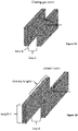
- FIG. 1A shows a configuration illustrating a parallel plate capacitor.
- capacitor plates move towards and away from each other in a direction denoted with x.
- x typically one of the plates is stationary, and the other plate moves closer to and further away from the other plate.
- Figure 1B shows a configuration illustrating an area modulated structure, also known as a linear comb structure.
- the plates move parallel to each other and capacitance behavior can be modeled with equation (2)
- C ⁇ h l + x d + C f
- d is a constant gap between the plates
- h a constant overlap dimension (height) of the plates
- I an initial overlap length
- x a displacement from the initial overlap length
- C f a static stray capacitance.
- the resonance frequency f of a harmonic oscillator is proportional to the electric spring constant.
- the sign of the electric spring constant k e is thus dependent on the second derivative term ⁇ C 2 / ⁇ x 2 .
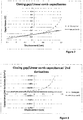
- the curves in figure 2 illustrate variation of exemplary capacitances in the closing gap and linear comb structures of figures 1A and 1B as a function of displacement from the initial position.
- the curves in figure 3 illustrate the corresponding behavior of the second derivative of these capacitances. It is seen that in commonly used prior art resonating structures, the second derivative is always positive (when parallel plate electrodes are used) or zero (in linear comb drive structures). However, for many applications further control to the electromechanical behavior of MEMS structures would be very valuable.
- Document US 2011 /018561 A1 discloses a capacitive sensor that includes first and second variable capacitor electrode sets, respectively disposed upon a planar support surface and a proof mass that is compliantly displaceable along a first axis substantially parallel to the planar support surface.
- the first electrode set produces a cyclic variation in capacitance over a range of displacement of the proof mass along the first axis
- the second electrode set produces an absolute capacitance variation throughout the range of displacement along the first axis.
- the combination of the two sensors enables a large dynamic range inertial sensor.
- Embodiments of the present invention include a MEMS structure that provides an improved way to selectively control electromechanical properties of a MEMS device by means of an applied voltage.
- the MEMS structure in the embodiments includes a capacitor element that comprises at least one stator element, and at least one rotor element suspended for motion parallel to a first direction in relation to the stator element.
- the stator element and the rotor element form the at least one capacitor element, wherein electrodes of the capacitor element are separated by a distance in a second direction that is perpendicular to the first direction, and the capacitance of the capacitor element is arranged to vary according to displacement of the rotor element from an initial position parallel to the first direction.
- the stator element and the rotor element are mutually oriented such that in at least one range of displacements of the rotor element from an initial position parallel to the first direction, the second derivative of the capacitance with respect to the displacement has negative values.
- the stator element includes a stator beam and a plurality of stator protrusions that extend from the stator beam towards the rotor beam.
- Each stator protrusion includes stator side surfaces on opposite sides of the stator protrusion, each stator side surface extending in the second direction; a stator end surface in the distal end of the stator protrusion, wherein the stator end surface extends in the first direction;
- the rotor element includes a rotor beam and a plurality of rotor protrusions that extend from the rotor beam towards the stator beam.
- Each rotor protrusion includes rotor side surfaces on opposite sides of the rotor protrusion, each rotor side surface extending in the second direction; a rotor end surface in the distal end of the rotor protrusion, wherein the rotor end surface extends in the first direction.
- the stator protrusions and the rotor protrusions are arranged into protrusion pairs so that the end surfaces of the protrusions of a protrusion pair at least partly overlap by facing each other, and at least one pair of side surfaces of the protrusions of a protrusion pair are aligned to a straight line in the second direction.
- Each protrusion pair forms a capacitor with a capacitance that is proportional to an overlap between the stator end surface and the rotor end surface of the protrusion pair, and thus arranged to vary according to the motion of the rotor parallel to the first direction
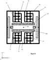
- Figure 4 illustrates an exemplary MEMS structure that includes a novel stator and rotor structure.
- the MEMS structure When incorporated into a MEMS device, the MEMS structure enables a specific way to adjust electromechanical properties of a MEMS device by an applied voltage. Due to the proposed design, the capacitance in the MEMS device can therefore be formed differently so that the second derivative term ⁇ C 2 / ⁇ x 2 in equation (5) can have also negative values.
- the proposed MEMS structure provides for a remarkably improved range for controlling the electromechanical properties of the MEMS device by means of an applied voltage.
- figure 4 includes only elements necessary to describe the principle of implementing the desired effect in MEMS devices.
- MEMS structures and MEMS devices typically include a plurality of further structural elements that are not specifically shown in the drawings herein.
- the MEMS structure is advantageously arranged into a planar form for alignment with a planar support structure.
- Directions parallel to the planar form of the MEMS structure are referred to as in-plane directions.
- Directions perpendicular to the planar form of the MEMS structure are referred to as out-of-plane directions.
- the MEMS structure includes at least one stator and at least rotor.
- the stator refers herein to parts of the MEMS structure that are anchored to the support structure such that they remain stationary in respect of the support structure.
- the rotor refers correspondingly to parts of the MEMS structure that are suspended to the support structure by one or more spring elements that allow at least one degree of freedom in respect of the support structure.
- the spring structures suspend the rotor for motion in one in-plane direction, herein referred to as a first direction and denoted in figure 4 as X-direction.
- the MEMS structure may be configured to comprise at least one capacitor element, a combination of one or more specific rotor elements and one or more specific stator elements coupled to form respectively one or more capacitors, the capacitance of which varies according to the displacement of the rotor in the first direction.
- the stator and the rotor elements include a plurality of protrusions that are arranged to face each other in a non-zero distance such that protrusion pairs are formed. These protrusion pairs form specific type of capacitors that implement the desired effect.
- the stator elements and rotor elements may be implemented in many forms.
- Figure 4 illustrates an exemplary configuration, where the rotor includes a rotor frame 15 and the rotor elements are coupled to the rotor frame 15 by means of rotor support beams 7a-7d.
- the suspension of the rotor frame is stiff in the Y-direction and flexible in the X-direction. It is noted that many types of known spring structures providing a degree of freedom in a specific direction may be applied within the scope.
- the rotor provides here an inertial mass that may move in respect of the static support.
- the rotor of figure 4 includes a rotor frame 15, which is movably anchored to a support structure (e.g. a substrate) by means of a spring structure.
- the suspending spring structure includes a first spring 4a and a second spring 4b.
- the inertial mass may take many forms and include also further mass structures, like comb structures that also move with the rotor frame 15 for further driving or sensing or quadrature compensation functions of the MEMS device, and/or rotor elements for other type of tuning of the electromechanical properties of the MEMS device.
- the inertial mass of the rotor is advantageously arranged to have point symmetry with respect to its center of mass CM, or reflectional symmetry in respect to an axis running through the center of mass CM.
- the rotor frame 15 may comprise a first stiff beam 2a, a second stiff beam 2b, a third stiff beam 2c, and a fourth stiff beam 2d rigidly connected to each other at the ends of the stiff beams to form a rectangular-shaped or square-shaped frame that is parallel with the underlying support structure.
- the first spring 4a connects with the rotor frame 15 in the middle of the first stiff beam 2a
- the second spring 4b connects with the rotor frame 15 in the middle of the second stiff beam 2b that is parallel with the first stiff beam 2a.
- the springs 4a and 4b are rigidly anchored to rotor anchoring elements 50a, 50b within the movable rotor frame 15.
- the rotor elements and stator elements include protrusions that are arranged to face each other in a distance.
- the role of the support beams in figure 4 is to provide a mechanical coupling between the rotor frame 15 and the one or more rotor elements, such that the protrusions in the one or more rotor elements initially face protrusions in respective stator elements, and the rotor elements are able to move parallel to a first direction in relation to the respective stator elements.
- the rotor frame 15 is shown to connect to rotor elements by means of rotor support beams 7a - 7d, which are arranged to move rigidly along motions of the rotor frame 15.
- the configuration of figure 4 includes four rotor support beams, two of which 7a, 7b extend inwards from the third stiff beam 2c and perpendicular to the direction of the third stiff beam, and two of which 7c, 7d extend inwards from the fourth stiff beam 2d and perpendicular to the direction of the fourth stiff beam.
- the fourth stiff beam 2d is parallel to the third stiff beam 2c.
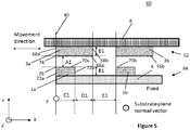
- Figure 5 illustrates in more detail an example of a capacitor element 60 that includes a rotor element 62 and a stator element 64.
- a rotor element 62 refers here to a part of the rotor that includes a rotor beam 8 and a plurality (two or more) of rotor protrusions 3a, 3b that extend away from the rotor beam, i.e. extend to a direction that is perpendicular to a longitudinal dimension of the rotor beam.
- the rotor protrusions are dimensional elements such that their distal end is designed to provide planar rotor end surfaces 66a, 66b that are parallel to the direction of the rotor motion, i.e. the first direction. The rotor end surfaces are brought to a distance from the rotor beams by side walls of the protrusions.
- rotor side surfaces 68a, 68b Two side wall surfaces that extend on opposite sides of a rotor protrusion (opposite when looked along the first direction) form rotor side surfaces 68a, 68b.
- the configuration in figure 5 is right-angled such that the rotor side surfaces 68a, 68b are orthogonal to a straight line in the first direction (X-direction in figure 5 ), and the rotor end surfaces 66a, 66b are orthogonal to a straight line in the second direction (Y-direction in figure 5 ).
- a stator element 64 refers here to a part of the stator that includes a stator beam 6 and a plurality (two or more) of stator protrusions 1a, 1b that extend away from the stator beam 6, i.e. extend to the second direction.
- the stator protrusions are correspondingly dimensional elements, and their distal end is designed to provide planar stator end surfaces 70a, 70b that are parallel to the direction of the rotor motion, i.e. the first direction.
- the stator end surfaces are brought to a distance from the stator beams by side walls of the protrusions.
- Two side wall surfaces that extend on opposite sides of a stator protrusion (opposite when looked along the first direction) form stator side surfaces 72a, 72b.
- the configuration in figure 5 is right-angled such that the stator side surfaces 72a, 72b are orthogonal to a straight line in the first direction, and the stator end surfaces 70a, 70b are orthogonal to a straight line in the second
- the rotor protrusions 3a, 3b extend from the rotor beam 8 perpendicularly outwards in the Y-direction, which is perpendicular to the X-direction movement of the rotor element, and parallel to the support structure that extends in the XY-plane.
- the rotor protrusions 3a, 3b include rotor side surfaces on opposite sides of each rotor protrusion. Each rotor side surface is thus in the YZ-plane that is perpendicular to the X-directed movement direction of the rotor element and perpendicular to the XY- plane of the support structure.
- Each of the rotor protrusions 3a, 3b includes a rotor end surface 66a, 66b in the distal end of the rotor protrusion.
- the rotor end surfaces are in the XZ-plane, which is parallel to the X-directed movement direction of the rotor and perpendicular to the XY- plane of the support structure.
- a rotor side edge 74 is formed between each rotor side surface and rotor end surface. In a right-angled configuration of figure 5 , a line following the rotor side edge is aligned to the Z-direction, i.e. orthogonal both with respect to the X-directed first direction and the Y-directed second direction.
- stator protrusions 1a, 1b may extend from the stator beam 6 perpendicularly outwards in the Y-direction, which is perpendicular to the X-direction movement of the rotor element, and parallel to the support structure that extends in the XY-plane.
- the stator protrusions 1a, 1b may include stator side surfaces 72a, 72b on opposite sides of each stator protrusion. Each stator side surface is thus in the YZ-plane that is perpendicular to the X-directed movement direction of the rotor element and perpendicular to the XY- plane of the support structure.
- Each of the stator protrusions 1a, 1b includes a stator end surface 70a, 70b in the distal end of the rotor protrusion.
- the stator end surfaces are in the XZ-plane, which is parallel to the X-directed movement direction of the rotor and perpendicular the XY- plane of the support structure.
- a stator side edge 76 is formed between each stator side surface and stator end surface. In a right-angled configuration of figure 5 , a line following the stator side edge is aligned to the Z-direction, i.e. orthogonal both with respect to the X-directed first direction and the Y-directed second direction.
- stator protrusions and the rotor protrusions are arranged into protrusion pairs so that the end surfaces of the protrusions of a protrusion pair at least partly overlap by facing each other on a distance, and side surfaces of the protrusions of a protrusion pair are aligned to a line in the second direction.
- the initial position refers here to a state of the structure when no external forces are applied and the spring structure is not flexed to either direction.
- a stator protrusion 1a and a rotor protrusion 3a form one protrusion pair and a stator protrusion 1b and a rotor protrusion 3b form another protrusion pair.
- Each of these protrusion pairs forms a capacitor with a capacitance that is proportional to an overlap between the stator end surface and the rotor end surface of the protrusion pair (linear comb structure).
- A1 denotes the distance between a stator protrusion 1a and a rotor protrusion 3a
- B1 denotes the Y-directed height of a rotor protrusion 3a and also the Y-directed height of a stator protrusion 1a
- C1 denotes the X-directed length of a stator protrusion 1a
- D1 denotes the X-directed length difference between a stator protrusion 1a and a rotor protrusion 3a
- E1 denotes the distance between two adjacent rotor protrusions 3a, 3b.
- C1 + D1 is the length of a rotor protrusion 3a
- D1 + E1 is the distance between two stator protrusions 1a, 1b.
- orthogonal projection of the rotor end surface 66a of the rotor protrusion 3a onto a straight line in the first direction at least partly overlaps orthogonal projection of the stator end surface 70a of the stator protrusion 1a onto the same straight line in the first direction.
- the orthogonal projection of the rotor end surface 66a of the rotor protrusion 3a in the first direction equals to the sum C1+D1.
- the orthogonal projection of the stator end surface 70a of the stator protrusion 1a in the first direction equals to C1.
- the overlap in the initial position thus equals to C1.
- At least one side surface of stator protrusion and one side of the rotor protrusion of a protrusion pair were defined to be aligned to a straight line in the second direction.
- the side surface 72a of the stator protrusion 1a and the side surface 68a of the rotor protrusion 3a are on the straight line 80.
- Point P thus represents the point where the orthogonal projections of the side edge of the rotor protrusions 3a and the stator protrusions 1a in the first direction coincide.
- figure 5 is not in scale, it is just shown to illustrate the meaning of the distances A1, B1, C1, D1, and E1 in an exemplary configuration.
- the end surfaces in the protruding parts of the stator and rotor elements may thus be arranged to an adjacent, non-zero distance from each other, which couples them to function as a capacitor.
- the overlapping area of the end surfaces of the stator and rotor protrusions changes when the facing end surfaces of the stator and rotor protrusions move into different positions with respect to each other. This means that the extent of how much the end surfaces of the stator and rotor protrusions face each other changes.
- the facing end surfaces of the stator and rotor protrusions are on a distance A1 from each other both in the initial position, and during and after movement
- stator protrusion 1a and the rotor protrusion 3a facing the stator 1a on a distance may form a protrusion pair.
- the overlap between the stator end surface 70a and the rotor end surface 66a changes.
- the two end surfaces 66a, 70a of the protrusion pair can thus be considered to form plates of an area modulated parallel plate capacitor, such that when the overlap decreases, the capacitance between the plates decreases, and vice versa.
- Figure 6A illustrates capacitance in an exemplary capacitor element with the claimed configuration as a function of displacement of the rotor.
- Figure 6B illustrates corresponding behavior of the second derivative term ⁇ C 2 / ⁇ x 2 as a function of displacement of the rotor.
- the capacitance is at maximum when the rotor element is in the initial position, and the overlap between the end surfaces is the greatest. When the displacement increases, the capacitance decreases.
- the curve of the second derivative term ⁇ C 2 / ⁇ x 2 has negative values.
- the curve of the second derivative term ⁇ C 2 / ⁇ x 2 has its minimum negative value immediately after the initial position, and rises along with the displacement.
- the protrusions may extend to one direction from a stator or rotor beam, or a stator or rotor beam may include protrusions that extend to two opposite directions from the stator or rotor beam.
- a set of rotor protrusions of a rotor beam 17a coupled to the rotor with rotor support beam 7a extend to the positive Y-direction, and they are arranged to face one set of stator protrusions.
- Another set of rotor protrusions of the same rotor beam 17a extend to the negative Y-direction, and they are arranged to face another set of stator protrusions.
- a set of rotor protrusions of a rotor beam 17b, also coupled to the rotor with rotor support beam 7a extend to the positive Y-direction only.
- protrusions of the stator and rotor elements into pairs, with and without the support beams.
- Figure 4 illustrates this alternative with rotor protrusions that are inside the rotor frame 15, arranged correspondingly to face the stator protrusions of a stator element on a non-zero distance from them.
- stator beams 6 may be transversally distributed along stator support beams 5a - 5d, and arranged to extend in the first direction X into a space between the rotor beams 6.
- the rotor beams 6 may be transversally distributed along the rotor support beams 7a - 7d, and extend in the first direction X into the space between the stator beams 8.
- the capacitive MEMS structure of figure 4 is arranged to be reflectionally symmetrical in respect of a line in X-direction that crosses the center of mass CM of the rotor.
- the MEMS structure can be included in a MEMS accelerometer device.
- Acceleration sensors are usually designed for open-loop measurement, which restricts their use to a limited acceleration range achievable with the mechanical construction and the conventional electrical tuning methods of the spring constant. With the presented structure, the full scale deflection of the element may be more flexibly adjusted. It is thus possible to provide, for example, a multi-range accelerometer with a remarkably larger measurement range.
- designing high-g acceleration sensors can be challenging as the complete testing of the element would require also use of high accelerations (centrifuge instead of testing with gravity).
- the presented structure enables creating an accelerometer design that can be tested in low-g range and operated in high-g range.
- the presented MEMS structure can be included in a resonator, a MEMS device with a resonating structure.
- Frequency tuning with an applied voltage is a commonly used method to fine-tune resonance frequency of a resonating structure, for example in resonators and gyroscopes.
- Common shortcoming of conventional tuning methods is that they can only decrease the resonance frequency, and the tuning needs high voltages.
- the presented MEMS design enables one to create resonating structures where the resonance frequency can be both decreased and increased with applied voltages. Furthermore the voltages needed for tuning are lower due to the possibility to tune the frequency up and down.
- the X-directed length C1+D1 of rotor end surface 66a is greater than the X-directed length C1 of stator end surface 70a. Accordingly, a displacement of the rotor in the positive X-direction causes a change in capacitance immediately after the initial position. On the other hand, when the rotor is displaced in the negative X-direction, the overlap area between the end surfaces of the protrusions remains the same even if the rotor moves from the initial position. Accordingly, the difference in the protrusion dimensions makes it possible to design the capacitor elements such that also direction of the rotor movement can be detected. This is an important aspect especially in accelerometer design.
- figure 4 shows a configuration where the X-directed length of stator end surfaces is less than the X-directed length of rotor end surfaces.
- the rotor elements in the upper part of the MEMS structure are coupled to the rotor frame 15 through rotor support beams 7a and 7b, and stator elements are coupled to a stator anchoring element 30a through stator support beams 5a and 5b.
- the stator elements are thus in the same potential and all capacitor elements in the upper part can contribute jointly to the detected capacitance variations.
- These upper capacitor elements are oriented such that displacement of the rotor in the positive X-direction causes a change in capacitance immediately after the initial position.
- the rotor is displaced in the negative X-direction, the overlap between the end surfaces in the capacitor elements remains the same and the detected capacitance does not change.
- the rotor elements in the lower part of the MEMS structure are coupled to the rotor frame 15 through rotor support beams 7c, 7d, and stator elements are coupled to an anchoring element 30b through stator support beams 5c, 5d.
- These lower capacitor elements are oriented such that displacement of the rotor in the negative X-direction causes a change in capacitance immediately after the initial position. On the other hand, when the rotor is displaced in the positive X-direction, the capacitance does not immediately change.
- the upper capacitor elements may be positioned to sense in combination displacements of the rotor in the positive X-direction, and lower capacitor elements to sense in combination displacements of the rotor in the negative X-direction.
- the range of sensitivity of the MEMS structure can be adjusted with an applied voltage, as described above.
- the stator support beams 5a, 5b are coupled through the stator anchoring element 30a to a first potential, and the stator support beams 5c, 5d through another anchoring element 30b to a second potential.
- the first potential and the second potential are advantageously the same.
- Figure 7 illustrates an alternative configuration for the MEMS structure suspended for in-plane motion. Also this MEMS structure is specifically applicable for accelerometer use, and provides the possibility to detect also the movement direction of the rotor. In addition, the illustrated configuration enables reduction in measurement error by differential detection.
- the MEMS structure of figure 7 corresponds to that of figure 4 , but includes four stator anchoring elements 32a-32d instead of two.
- Each stator anchoring element 32a - 32d supports one stator support beam 5a, 5b, 5c or 5d anchored thereto.
- the capacitive micromechanical sensor structure of figure 7 is reflectionally symmetrical in both X-direction and Y-direction.
- a line of symmetry is a horizontal line in the X-direction across the middle of the element structure, advantageously a horizontal line crossing the center of mass CM of the rotor.
- Another line of symmetry is a line that is perpendicular to the horizontal line, and also runs in the Y-direction through the middle of the element structure, advantageously also crossing the center of mass CM of the rotor.
- stator elements coupled to a first anchoring element 32a through a first stator support beam 5a and rotor elements coupled to the rotor frame 15 through the first rotor support beam 7a form a first detection element.
- stator elements coupled to a second anchoring element 32b through a second stator support beam 5b and rotor elements coupled to the rotor frame 15 through the second rotor support beam 7b form a second detection element.
- Stator elements coupled to a third anchoring element 32c through a third stator support beam 5c and rotor elements coupled to the rotor frame 15 through the third rotor support beam 7c form a second detection element
- stator elements coupled to a fourth anchoring element 32d through a fourth stator support beam 5d and rotor elements coupled to the rotor frame 15 through the fourth rotor support beam 7d form a fourth detection element.
- the first, second, third and fourth detection elements are positioned such that the first and the third detection element detect displacements of the rotor in the positive X-direction, and the second and the fourth detection element detect displacements of the rotor in the negative X-direction.
- the output signal of the MEMS structure may be arranged to correspond with the difference between the sum of contributions by the first and the third detection element and the sum of contributions by the second and the fourth element. Such differential detection helps to eliminate effects of manufacturing errors and temperature variations in the MEMS device configuration.
- Figure 8 illustrates an alternative configuration for a MEMS structure that provides the possibility to detect in-plane movement direction of the rotor, and enables elimination of errors by differential detection.
- the MEMS element of figure 8 otherwise corresponds to that of figure 7 , but the detection elements are differently positioned for differential detection.
- the MEMS structure of figure 85 is reflectionally symmetrical in the Y-direction.
- the line of symmetry is aligned to Y-direction across the middle of the element structure, and advantageously crosses the center of the mass CM of the rotor.
- the first, second, third and fourth detection elements are positioned such that the first and the fourth detection element detect displacements of the rotor in the positive X-direction, and the second and the third detection element detect displacements of the rotor in the negative X-direction.
- the output signal may correspond with the difference between the sum of contributions by the first and the fourth detection element and the sum of contributions by the second and the third element.
- the differential detection helps to eliminate effects of manufacturing errors and temperature variations in the MEMS device configuration.
- the cross-coupled configuration coupling the first and the fourth detection elements, and the second and the third detection elements placed cross-wise parallel to the support structure may be even more effective in eliminating effects of some manufacturing errors and temperature variations in the MEMS device configuration.
- the rotor protrusions 3 and the stator protrusions 1 are of mutually different length in the X-direction to enable direction detection, as described above.
- the rotor protrusions and the stator protrusions are of the same height in the Y-direction. This is advantageous for symmetry and mass distribution of the rotor.
- also configurations with different heights in the Y-direction may be applied within the scope.
- the X-direction length of the rotor protrusions is greater than that of the stator protrusions.
- configurations where X-direction length of the stator protrusions is greater than that of the rotor protrusions may also be applied within the scope.
- Figure 9 shows an in-plane moving MEMS structure specifically useful for resonator applications.
- the MEMS element of figure 9 otherwise corresponds to that of figure 4 but the X-direction lengths of the stator protrusions and the rotor protrusions are equal, or almost equal.
- the capacitive micromechanical sensor structure of figure 9 is reflectionally symmetrical in the X-direction.
- the line of symmetry is a horizontal line in the X-direction across the middle of the element structure, advantageously crossing the center of mass CM of the rotor.
- stator support beams 5a, 5b are coupled through a stator anchoring element 30a to a first potential, and the stator support beams 5c, 5d through another stator anchoring element 30b to a second potential.
- the first potential and the second potential are advantageously the same.
- the first, second, third and fourth detection elements are positioned such that the first and second detection elements that include the upper capacitor elements contribute to a signal in combination, and the third and the fourth detection elements that include the lower capacitor elements contribute to another signal in combination.
- Alternative differential configurations that correspond with configurations of Figure 7 and 8 may be applied, as well. With the disclosed configurations, the resonance frequency of the resonator can be effectively adjusted with an applied voltage, as described above.
- Figure 10 presents a partial detail view of an exemplary MEMS structure of figure 9 .
- the denotations are similar to the ones used in figure 5 .
- A1 denotes the distance between a stator protrusion 1a and a rotor protrusion 3a
- B1 denotes the Y-directed height of a rotor protrusion 3a and also the Y-directed height of a stator protrusion 1a
- C1 denotes the X-directed length of a stator protrusion 1a
- D1 denotes the X-directed length difference between a stator protrusion 1a and a rotor protrusion 3a
- E1 denotes the distance between two adjacent rotor protrusions 3a, 3b.
- C1 + D1 is the length of a rotor protrusion 3a and D1 + E1 is the distance between two stator protrusions 1a, 1b.
- the stator end surface 70a of each stator protrusion 1a fully overlaps the rotor end surface 66a of a respective rotor protrusion 3a that faces it in a distance.
- the overlap of the end surfaces and thereby the capacitance between them changes.
- figure 10 is not in scale, it is just shown to illustrate the meaning of the denotations A1, B1, C1, D1 and E1.
- the rotor motion has been arranged to take place in the in-plane direction, i.e. parallel to the plane of an underlying support structure.
- the described structures may be applied also to MEMS structures with out-of-plane moving elements.
- Figure 11 shows an exemplary MEMS structure with an out-of-plane moving rotor configuration, specifically applicable for accelerometer use. Elements corresponding to elements in the earlier embodiments are denoted with same numerals, and more information on them may be referred from the earlier description.
- the MEMS structure comprises again at least one stator that is rigidly anchored to a support structure and at least one rotor movably anchored by means of a flexural spring structure to the support structure.
- the substrate plane is parallel to the XY-plane and the movement of the rotor is arranged to take place parallel to the Z-direction.
- the Z-direction is the first direction and the X-direction is the second direction.
- the stator includes stator anchoring elements 30a, 30b, and a plurality of stator beams 6 coupled to the anchoring elements 30a, 30b.
- the stator beams 6 extend from a respective anchoring element in the Y-direction, and have also a height dimension in the Z-direction.
- Each stator beam 6 includes a plurality (two or more) stator protrusions 1.
- the stator protrusions 1 extend from the stator beam 6 in the X-direction outwards from stator beams 6 and perpendicular to the Z-directed movement direction (first direction) of the rotor element.
- the rotor is suspended from a rotor anchoring element 40 through a rigid rotor support structure 41 and with suspension springs 4a, 4b.
- the rotor includes a rotor frame 15 that may be induced into rotational movement about an axis running through the torsional springs 4a, 4b.
- a plurality of rotor beams 8 extend inwards from the distal end of the rotor fame 15 in the Y-direction, and have also a height dimension in the Z-direction.
- the rotor beams 8 include a plurality of rotor protrusions 3 distributed along the height dimension of each rotor beam 8.
- the rotor protrusions 3 extend from the rotor beams 8 in the X-direction outwards from the rotor beam 8, i.e. in a direction perpendicular to the Z-directed movement direction of the rotor element.
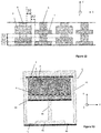
- FIG 12 illustrates the configuration shown in figure 11 with a partial detail cross-sectional view of a part of a MEMS structure, only with a smaller amount of beams than figure 11 .
- each stator protrusion 1 includes stator side surfaces 72a, 72b on opposite sides of the stator protrusion 1. Each stator side surface is parallel with the XY-plane.
- Each stator protrusion 1 also includes a stator end surface 70 in the distal end of the stator protrusion 1, wherein the stator end surface is parallel with the YZ-plane.
- each rotor protrusion 3 includes rotor side surfaces 68a, 68b on opposite sides of the rotor protrusion 3, each rotor side surface 68a, 68b being parallel to the XY-plane.
- Each rotor protrusion 3 also includes a rotor end surface in the distal end of the rotor protrusion, wherein the rotor end surface is parallel with the YZ-plane.
- the rotor protrusions 3 may extend from one side or from both sides of the rotor beam 8.
- the stator protrusions 1 and the rotor protrusions 3 are arranged into protrusion pairs so that a protrusion pair can consist of stator and rotor protrusions of adjacent stator and rotor beams.
- the rotor frame is a U-shaped structure with two side beams and an end beam. As shown in figure 11 , one of the side beams of the rotor frame 15 is connected at one end by means of a first spring 4a to a rotor support structure 41. The opposite side beam of the element frame 15 is connected at one end by means of a second spring 4b to the same rotor support structure 41. The opposite side beams of the element frame are parallel with a central axis of the element structure.
- the rotor support structure 41 may be rigidly anchored to the substrate at a rotor anchoring element 40.
- the springs 4a, 4b are torsionally flexible and thereby enable the rotational out-of plane motion of the rotor.
- stator beams 6 (on which there are stator protrusions 1) are shown to extend into the space between the rotor beams 8 (on which there are rotor protrusions 3).
- the stator and the rotor thus include two groups, where rotor beams of both groups are in the same potential, but stator beam groups can be coupled to a same potential or a different potential.
- stator beams 6 face a space between the rotor and stator element groups and the rotor beams 8 are outmost.
- the sides of the stator beams 6 that face the first space between the groups can include protrusions, as shown in figure 11 , or be free from stator protrusions.
- the sides of the rotor beams 8, that face the rotor frame 15 can include protrusions, as shown in figure 11 , or be free of rotor protrusions.
- the MEMS structure of figure 11 is reflectionally symmetrical in the Y-direction.
- the stator and rotor element groups preferably comprise the same number of protrusion pairs so that the groups are disposed symmetrically with respect to a Y-directed axis of the MEMS structure that crosses the center of mass CM of the rotor.
- Figure 12 illustrates in more detail the stator beams 6 with stator protrusions 1 and the rotor beams 8 with rotor protrusions 3.
- the rotor protrusions 3 and the stator protrusions 1 have mutually different heights in the Z-direction (the moving direction), and thereby enable detection of direction of the rotor movement, as well.
- the Z-direction height of the rotor protrusions 3 is greater than the Z-directed height of the stator protrusions 1.
- a configuration where the Z-direction height of the stator protrusions 1 is greater than the Z-directed height of the rotor protrusions 3 may be applied within the scope, as well.
- Figure 12 illustrates in more detail also dimensions of the stator and rotor elements described in figure 11 .
- A2 denotes the distance between the facing end surfaces of a stator protrusion 1 and a rotor protrusion 3
- B2 denotes the X-directed length of a rotor protrusion 3 from the rotor beam 8, i.e. the distance of the distal end of a rotor protrusion 3 to the rotor beam 8.
- C2 denotes the Z-directed height of a rotor protrusion 1
- D2 denotes the height difference between a rotor protrusion 3 and a stator protrusion 1
- E2 denotes the distance between two rotor protrusions 3.
- figure 11 is not in scale, it is just shown to illustrate the meaning of the distances A2, B2, C2, D2 and E2.
- Figure 13 presents an exemplary MEMS structure with an out-of-plane moving rotor for use in resonator applications.
- the structure provides for the enhanced tuning, as described above, but does not enable detection of the movement direction.
- the structure of figure 13 is similar to that of figure 11 , and the reference numbers thus relate to similar entities, if not stated otherwise.
- the stator element includes a plurality of stator beams 6 anchored in the Y-direction to a stator anchoring element 30 and a plurality of rotor beams 8 rigidly connected in the Y-direction to the rotor frame 15 placed on a support structure (not shown).
- a stator beam 6 has several stator protrusions 1 that extend along the Z-direction dimension of each stator beam 6 in the X-direction, and several rotor protrusions 3 that extend in the Z-direction dimension along each rotor beam 8 in the X-direction.
- the stator protrusions and the rotor protrusions for protrusion pairs otherwise like in figure 11 , but in figure 13 , the stator and rotor protrusions are of the same height in the Z-direction.
- the rotor and stator beams are interleaved like in the MEMS structure of figure 11 .
- the capacitive micromechanical sensor structure of figure 13 has reflectional symmetry in respect of an axis the Y-direction.
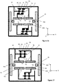
- Figure 14 shows a further exemplary configuration for a MEMS structure.
- the rotor beams 8 and stator beams 6 are arranged into two groups, as in figure 11 .
- the stator beams 6 of one of the groups are anchored to the stator anchoring element 30a and the stator beams 6 in the other group are anchored to the stator anchoring element 30b.
- the Z-directed height dimension of the rotor protrusions is equal to the Z-directed height dimension of the stator protrusions, as in the MEMS structure of figure 13 .
- Figure 15 illustrates the configuration presented in figure 14 with a partial detail cross-sectional view of stator and rotor elements in a similar structure, only with a different number of stator and rotor beams.
- the cross section of figure 15 is taken along plane V of figure 14 .
- the stator beams 6 include stator protrusions 1
- the rotor beams 8 include rotor protrusions 3. It can be seen that the rotor protrusions 3 and the stator protrusions 1 are of the same height in the Z-direction (the first direction, the moving direction of the rotor).
- Figure 15 illustrates also dimensions of rotor and stator protrusions along the Z-directed dimension of stator and rotor beams, applicable in MEMS structures of figures -13-14.
- reference number 3 denotes rotor protrusions and reference number 1 stator protrusions.
- A2 denotes the distance between the facing end surfaces of a stator protrusion 1 and a rotor protrusion 3
- B2 denotes the X-directed length of a rotor protrusion 3 from the rotor beam 8, i.e. the distance of the distal end of a rotor protrusion 3 to the rotor beam 8.
- C2 denotes the Z-directed height of a rotor protrusion 3 and also the Z-directed height of a stator protrusion 1
- E2 denotes the distance between two rotor protrusions 3 and also the distance between two stator protrusions 1. It is pointed out that figure 15 is not in scale, it is just shown to illustrate the meaning of the distances A2, B2, C2 and E2.
- Figure 16 illustrates a further embodiment for an in-plane configuration, i.e. a MEMS structure with an in-plane moving rotor.
- the embodiment enables the possibility to use differential detection, and detect also the movement direction.
- the described MEMS structure is therefore again specifically applicable for accelerometer use.
- stator anchoring elements 30a - 30d there are four stator anchoring elements 30a - 30d, to which one or more (one shown) stator support beams 5a, 5b, 5c or 5d are coupled to.
- a rotor beam 8f is interleaved between stator beams 6f and 6g.
- the stator element of the stator beam 6f includes a plurality of stator protrusions 1f that extend in the positive Y-direction from the stator beam 6f towards the rotor beam 8f.
- the stator element of the stator beam 6g includes a plurality of stator protrusions 1g that extend in the negative Y-direction from the stator beam 6g towards the rotor beam 8f.
- the rotor element of the rotor beam 8f includes a plurality of rotor protrusions 3f that extend in the negative Y-direction towards the stator beam 6f, and a plurality of rotor protrusions 3g that extend in the positive Y-direction towards the stator beam 6g.
- a stator protrusion 1f and a rotor protrusion 3f form a protrusion pair, wherein a side surface of stator protrusion 1f and a side surface of the rotor protrusion 3f of the protrusion pair run along on a straight line 81 in the Y-direction.
- a stator protrusion 1g and a rotor protrusion 3g form another protrusion pair, where a side surface of stator protrusion 1g and a side surface of the rotor protrusion 3g of the protrusion pair run along a straight line 80 in the Y-direction.
- movement of the rotor in the positive X-direction causes a change in the overlap, and thus in capacitance between capacitors formed by protrusions of the stator element supported by the stator support beam 5b and protrusions of the rotor element supported by the rotor support beam 7a.
- movement of the rotor in the negative X-direction causes a change in the overlap, and thus in capacitance between capacitors formed by protrusions of the stator element supported by the stator support beam 5a and protrusions of the rotor element supported by the rotor support beam 7a.
- Figure 17 illustrates a corresponding configuration for resonator applications.
- the MEMS structure is by far similar to the MEMS structure, but the X-directed length of the stator protrusions may now be equal to the X-directed length of the rotor protrusions.
- the MEMS devices may include in-plane moving configurations where the rotor moves in a direction parallel to a plane of a support structure, out-of -plane moving configurations where the rotor moves in a direction perpendicular to the plane of the support structure, or both.
- X-, Y- and Z- directions are used herein to explain the orientation of different parts of the protrusions in three dimensions in accordance with the principle of the three-dimensional Cartesian coordinates ( x , y , z ) in an orthogonal coordinate system. Its coordinate surfaces are planes that meet at right angles to one another, i.e., are perpendicular.
- the capacitor plates are not interleaved.
- the capacitor plates are arranged so that the second derivative of their capacitance is minimized as a function of the movement of the rotor.
- This kind of a structure can be combined with traditional tuning structures. Accordingly, as the proposed capacitors can be used to tune resonance frequency up, it is possible to use, for example, traditional parallel plate capping wafer electrode(s) for tuning the resonance frequency down.
- the MEMS devices may include in-plane moving configurations, out-of -plane moving configurations, or both configurations.
- a voltage applied across the opposed sets of protrusions produces electrostatic force fields in the gap between the opposed protrusions.
- This phenomenon can be used to drive a resonating structure with alternating voltage (AC voltage).
- the same structure can be used to tune the resonance frequency by inducing static voltage (DC voltage) across the protrusions that make up the conductor plates.
- the proposed technique for tuning, setting, defining, trimming and/or selecting the output frequency of a microelectromechanical (MEMS) resonator overcomes the shortcomings of conventional techniques, and enables resonance frequency shifts toward higher frequencies.
- the proposed configuration has increased resonance frequency in a Z-axis element by 3 % when using 2.5 V voltage between the overlapping end surfaces of the electrodes, and 12 % when using 10 V voltage.
- a 12 % resonance frequency increase means a 25 % increase in element fullscale and measuring range.
Claims (17)
- Mikroelektromechanische Struktur, die ein Kondensator-Element (60) aufweist, das mindestens ein Stator-Element (64, 6, 1, 1a, 1b) und mindestens ein Rotor-Element (62, 8, 3, 3a, 3b), das für eine parallel zu einer ersten Richtung im Verhältnis zum Stator-Element (64, 6, 1, 1a, 1b) verlaufende Bewegung aufgehängt ist, umfasst;
wobei das Stator-Element (64, 6, 1, 1a, 1b) und das Rotor-Element (62, 8, 3, 3a, 3b) mindestens ein Kondensator-Element ausbilden, wobei Elektroden des Kondensator-Elements in einer zweiten Richtung, die senkrecht zu der ersten Richtung ist, durch einen Abstand (A1, A2) getrennt sind, und die Kapazität des Kondensator-Elements so eingerichtet ist, dass sie sich, entsprechend den Verschiebungen des Rotor-Elements (62, 8, 3, 3a, 3b) ab einer Ausgangsposition in der ersten Richtung, verändert, dadurch gekennzeichnet, dass
das Stator-Element einen Statorbalken (6) und mehrere Stator-Vorsprünge (1, 1a, 1 b), die sich vom Statorbalken (6) aus in der zweiten Richtung erstrecken, aufweist, wobei jeder Stator-Vorsprung (1, 1a, 1b) umfasst:Stator-Seitenflächen (72a, 72b) an entgegengesetzten Seiten des Stator-Vorsprungs, wobei sich jede Stator-Seitenfläche in der zweiten Richtung erstreckt;eine Stator-Endfläche (70a) am fernen Ende des Stator-Vorsprungs, wobei sich die Stator-Endfläche in der ersten Richtung erstreckt;das Rotor-Element einen Rotorbalken (8) und mehrere Rotor-Vorsprünge (3, 3a, 3b), die sich vom Rotorbalken aus in der zweiten Richtung in Richtung des Stator-Elements erstrecken, aufweist, wobei jeder Rotor-Vorsprung umfasst:Rotor-Seitenflächen (68a, 68b) an entgegengesetzten Seiten des Rotor-Vorsprungs, wobei sich jede Rotor-Seitenfläche in der zweiten Richtung erstreckt;eine Rotor-Endfläche (66a) am fernen Ende des Rotor-Vorsprungs, wobei sich die Rotor-Endfläche in der ersten Richtung erstreckt;in der Ausgangsposition die Stator-Vorsprünge (1, 1a, 1b) und die Rotor-Vorsprünge (3, 3a, 3b) in Vorsprungpaaren angeordnet sind, so dass die Endflächen (66a, 70a) der Vorsprünge eines Vorsprungpaares einander in Gegenüberstellung mindestens teilweise überlappen und mindestens ein Paar von Seitenflächen (68a, 72a) der Vorsprünge eines Vorsprungpaares zu einer geraden Linie in der zweiten Richtung ausgerichtet ist;
jedes Vorsprungpaar einen Kondensator mit einer Kapazität bildet, die proportional zu einer Überlappung zwischen der Stator-Endfläche (70a) und der Rotor-Endfläche (66a) des Vorsprungpaares ist und somit so eingerichtet ist, dass sie sich entsprechend der parallel zur ersten Richtung verlaufenden Bewegung des Rotors verändert;
wodurch das Stator-Element (64, 6, 1, 1a, 1b) und das Rotor-Element (62, 8, 3, 3a, 3b) zueinander so ausgerichtet sind, dass, in mindestens einem Bereich von Verschiebungen des Rotor-Elements (62, 8, 3, 3a, 3b) aus der Ausgangsposition in der ersten Richtung, die zweite Ableitung der Kapazität in Bezug auf die Verschiebung negative Werte aufweist. - Mikroelektromechanische Struktur nach Anspruch 1, dadurch gekennzeichnet, dass das Stator-Element (64, 6, 1, 1a, 1b) und das Rotor-Element (62, 8, 3, 3a, 3b) zueinander so ausgerichtet sind, dass ein Bereich von Verschiebungen des Rotor-Elements (62, 8, 3, 3a, 3b), in welchem die zweite Ableitung der Kapazität in Bezug auf die Verschiebung negative Werte aufweist, unmittelbar nach der Verschiebung aus der Anfangsposition beginnt.
- Mikroelektromechanische Struktur nach Anspruch 1 oder 2, dadurch gekennzeichnet, dass das Stator-Element (64, 6, 1, 1a, 1b) und das Rotor-Element (62, 8, 3, 3a, 3b) zueinander so ausgerichtet sind, dass die zweite Ableitung der Kapazität in Bezug auf die Verschiebung unmittelbar nach Verschiebung aus der Anfangsposition ein Minimum aufweist.
- Mikroelektromechanische Struktur nach Anspruch 1, dadurch gekennzeichnet, dass für jedes Vorsprungpaar die Länge der Stator-Endfläche (70a) in der ersten Richtung und die Länge der Rotor-Endfläche (66a) in der ersten Richtung gleich groß sind.
- Mikroelektromechanische Struktur nach Anspruch 1, dadurch gekennzeichnet, dass für jedes Vorsprungpaar die Länge (C1) der Stator-Endfläche (70a) in der ersten Richtung von der Länge (C1+D1) der Rotor-Endfläche (66a) in der ersten Richtung abweicht.
- Mikroelektromechanische Struktur nach einem der Ansprüche 1 bis 5, dadurch gekennzeichnet, dass in den Vorsprungpaaren die Höhe entlang der zweiten Richtung (B1) des Stator-Vorsprungs (1a) gleich der Höhe entlang der zweiten Richtung des Rotor-Vorsprungs (3a) des Vorsprungpaares ist.
- Mikroelektromechanische Struktur nach Anspruch 6, dadurch gekennzeichnet, dass die Höhe entlang der zweiten Richtung (B1) der Stator-Vorsprünge und der Rotor-Vorsprünge 1 bis 4 Mal, bevorzugt 2 bis 3 Mal so groß wie der Abstand (A1) zwischen den gegenüberliegenden Stator- und Rotor-Endflächen ist.
- Mikroelektromechanische Struktur nach einem der Ansprüche 5 bis 7, dadurch gekennzeichnet, dass die Länge (C1, C1+D1; C2, C2+D2) der Stator- oder der Rotor-Endfläche in der ersten Richtung 1 bis 3 Mal, bevorzugt 1,5 bis 2,5 Mal so groß wie der Abstand (A1; A2) zwischen den gegenüberliegenden Stator- und Rotor-Endflächen ist.
- Mikroelektromechanische Struktur nach einem der Ansprüche 5 bis 8, dadurch gekennzeichnet, dass die Differenz (D1; D2) zwischen der Länge der Rotor-Endfläche und der Stator-Endfläche in der ersten Richtung 0,5 bis 3,5 Mal, bevorzugt 1,5 bis 2,5 Mal so groß wie der Abstand (A1; A2) zwischen Seitenflächen der gegenüberliegenden Stator- und Rotor-Vorsprünge ist.
- Mikroelektromechanische Struktur nach Anspruch 9, dadurch gekennzeichnet, dass ein Abstand (E1; E2) zwischen zwei benachbarten Rotor-Seitenflächen oder zwischen zwei benachbarten Stator-Seitenflächen 1 bis 4 Mal, bevorzugt 2 bis 3 Mal so groß wie der Abstand (A1; A2) zwischen den gegenüberliegenden Stator- und Rotor-Endflächen ist.
- Mikroelektromechanische Struktur nach einem der Ansprüche 1 bis 10, dadurch gekennzeichnet, dass sie mindestens zwei Erfassungselemente umfasst, wobeijedes Erfassungselement ein oder mehrere Kondensator-Elemente umfasst, deren Stator-Elemente am gleichen Potenzial angeschlossen sind,eines der mindestens zwei Erfassungselemente so positioniert ist, dass es Verschiebungen des Rotors in einer positiven Richtung parallel zur ersten Richtung erfasst, und ein anderes der mindestens zwei Erfassungselemente so positioniert ist, dass es Verschiebungen des Rotors in einer negativen Richtung parallel zur ersten Richtung erfasst, wobei die negative Richtung entgegengesetzt zur ersten Richtung ist;jedes Erfassungselement ein oder mehrere Kondensator-Elemente aufweist, wobei Stator-Elemente jedes im Erfassungselement enthaltenen Kondensator-Elements elektrisch gekoppelt sind, um ein Signal zur Differentialerfassung bereitzustellen.
- Mikroelektromechanische Struktur nach Anspruch 11, dadurch gekennzeichnet, dass sie mindestens vier Erfassungselemente in einer kreuzgekoppelten Konfiguration aufweist, wobei:ein erstes Erfassungselement und ein viertes Erfassungselement Verschiebungen des Rotors in der positiven Richtung parallel zur ersten Richtung erfassen,ein zweites Erfassungselement und ein drittes Erfassungselement Verschiebungen des Rotors in einer negativen Richtung parallel zur ersten Richtung erfassen,Stator-Elemente jedes im Erfassungselement enthaltenen Kondensator-Elements elektrisch gekoppelt sind, um ein Ausgangssignal bereitzustellen, das der Differenz zwischen der Summe der Beiträge des ersten und des vierten Erfassungselements und der Summe der Beiträge des zweiten und dritten Elements entspricht.
- Mikroelektromechanische Struktur nach einem der Ansprüche 1 bis 12, dadurch gekennzeichnet, dassdie mikroelektromechanische Struktur eine planare Form zur Ausrichtung an einer planaren Stützstruktur aufweist;die erste Dimension, parallelbeweglich zu der das Rotor-Element (62, 8, 3, 3a, 3b) aufgehängt ist, eine In-Plane-Richtung ist, die parallel zur Ebene der planaren Form der mikroelektromechanischen Struktur ist.
- Mikroelektromechanische Struktur nach einem der Ansprüche 1 bis 10, dadurch gekennzeichnet, dassdie mikroelektromechanische Struktur eine planare Form zur Ausrichtung an einer planaren Stützstruktur aufweist;die erste Dimension, parallelbeweglich zu der das Rotor-Element (8, 3) aufgehängt ist, eine Out-of-Plane-Richtung ist, die senkrecht zur Ebene der planaren Form der mikroelektromechanischen Struktur ist.
- Mikroelektromechanische Struktur nach Anspruch 14, dadurch gekennzeichnet, dassdie zweite Richtung parallel zur Ebene der planaren Form der mikroelektromechanischen Struktur ist,der Statorbalken (6) eine Höhendimension in der ersten Richtung aufweist und die Stator-Vorsprünge (1) entlang der Höhendimension des Statorbalkens (6) verteilt sind.
- Mikroelektromechanische Vorrichtung, die die mikroelektromechanische Struktur nach einem der Ansprüche 1 bis 15 umfasst.
- Mikroelektromechanische Vorrichtung nach Anspruch 16, dadurch gekennzeichnet, dass die mikroelektromechanische Vorrichtung ein Beschleunigungsmesser oder ein Resonator ist.
Applications Claiming Priority (2)
| Application Number | Priority Date | Filing Date | Title |
|---|---|---|---|
| FI20155153A FI127229B (en) | 2015-03-09 | 2015-03-09 | Microelectromechanical structure and device |
| PCT/IB2016/051265 WO2016142832A1 (en) | 2015-03-09 | 2016-03-07 | A microelectromechanical capacitive sensor structure and device |
Publications (2)
| Publication Number | Publication Date |
|---|---|
| EP3268305A1 EP3268305A1 (de) | 2018-01-17 |
| EP3268305B1 true EP3268305B1 (de) | 2021-05-19 |
Family
ID=55588322
Family Applications (1)
| Application Number | Title | Priority Date | Filing Date |
|---|---|---|---|
| EP16711347.1A Active EP3268305B1 (de) | 2015-03-09 | 2016-03-07 | Mikroelektromechanische kapazitive sensorstruktur und vorrichtung |
Country Status (7)
| Country | Link |
|---|---|
| US (1) | US9969606B2 (de) |
| EP (1) | EP3268305B1 (de) |
| JP (1) | JP6627883B2 (de) |
| CN (1) | CN107406250B (de) |
| FI (1) | FI127229B (de) |
| TW (1) | TWI619668B (de) |
| WO (1) | WO2016142832A1 (de) |
Families Citing this family (9)
| Publication number | Priority date | Publication date | Assignee | Title |
|---|---|---|---|---|
| DE102017217009B3 (de) * | 2017-09-26 | 2018-07-19 | Robert Bosch Gmbh | MEMS-Vorrichtung sowie entsprechendes Betriebsverfahren |
| JP7056099B2 (ja) * | 2017-11-28 | 2022-04-19 | セイコーエプソン株式会社 | 物理量センサー、物理量センサーデバイス、複合センサーデバイス、慣性計測装置、移動体測位装置、携帯型電子機器、電子機器および移動体 |
| US10712359B2 (en) * | 2018-05-01 | 2020-07-14 | Nxp Usa, Inc. | Flexure with enhanced torsional stiffness and MEMS device incorporating same |
| US10794701B2 (en) | 2018-05-01 | 2020-10-06 | Nxp Usa, Inc. | Inertial sensor with single proof mass and multiple sense axis capability |
| CN109490576A (zh) * | 2018-12-19 | 2019-03-19 | 成都力创云科技有限公司 | 一种基于soi的全差分电容式mems加速度计 |
| CN112014595B (zh) * | 2019-05-30 | 2022-10-28 | 武汉杰开科技有限公司 | 加速度计及其制作方法 |
| CN112014596B (zh) * | 2019-05-30 | 2022-10-28 | 武汉杰开科技有限公司 | 加速度计及其制作方法 |
| KR20220150927A (ko) * | 2020-03-03 | 2022-11-11 | 인피콘, 인크. | 반도체 공정을 모니터링하기 위한 시스템 및 방법 |
| JP7389767B2 (ja) | 2021-02-26 | 2023-11-30 | 株式会社東芝 | センサ及び電子装置 |
Family Cites Families (18)
| Publication number | Priority date | Publication date | Assignee | Title |
|---|---|---|---|---|
| JP3960502B2 (ja) * | 1999-03-16 | 2007-08-15 | 学校法人立命館 | 静電容量型センサ |
| JP4063057B2 (ja) * | 2002-11-20 | 2008-03-19 | 株式会社デンソー | 容量式加速度センサ |
| US20040231420A1 (en) | 2003-02-24 | 2004-11-25 | Huikai Xie | Integrated monolithic tri-axial micromachined accelerometer |
| US7469588B2 (en) | 2006-05-16 | 2008-12-30 | Honeywell International Inc. | MEMS vertical comb drive with improved vibration performance |
| EP2132868A1 (de) * | 2007-04-03 | 2009-12-16 | STMicroelectronics S.r.l. | Kapazitives system zum positionsgeben für elektrostatischer mikromotor |
| EP1998345A1 (de) | 2007-05-31 | 2008-12-03 | Infineon Technologies SensoNor AS | Verfahren zur Herstellung kapazitiver Elemente für eine kapazitive Vorrichtung |
| US7690254B2 (en) | 2007-07-26 | 2010-04-06 | Honeywell International Inc. | Sensor with position-independent drive electrodes in multi-layer silicon on insulator substrate |
| WO2009120193A1 (en) * | 2008-03-26 | 2009-10-01 | Hewlett-Packard Development Company, L.P. | Capacitive sensor having cyclic and absolute electrode sets |
| JP2010286471A (ja) * | 2009-05-15 | 2010-12-24 | Seiko Epson Corp | Memsセンサー、電子機器 |
| CN101871952B (zh) * | 2010-06-11 | 2012-07-11 | 瑞声声学科技(深圳)有限公司 | Mems加速度传感器 |
| AT11920U3 (de) | 2010-08-12 | 2012-03-15 | Oesterreichische Akademie Der Wissenschaften | Verfahren zur herstellung einer mems-vorrichtung mit hohem aspektverhältnis, sowie wandler und kondensator |
| US20120048019A1 (en) * | 2010-08-26 | 2012-03-01 | Hanqin Zhou | Highly sensitive capacitive sensor and methods of manufacturing the same |
| TWI649565B (zh) * | 2012-01-12 | 2019-02-01 | 芬蘭商村田電子公司 | 加速度感測器結構和其之使用 |
| US20130229747A1 (en) * | 2012-03-01 | 2013-09-05 | Agilent Technologies, Inc. | Balanced voltage variable capacitor device |
| US20150177272A1 (en) | 2012-06-13 | 2015-06-25 | Purdue Research Foundation | Microelectromechanical system and methods of use |
| JP5783201B2 (ja) * | 2013-03-27 | 2015-09-24 | 株式会社デンソー | 容量式物理量センサ |
| FI126199B (en) * | 2013-06-28 | 2016-08-15 | Murata Manufacturing Co | CAPACITIVE MICROMECHANICAL SENSOR STRUCTURE AND MICROMECHANICAL ACCELEROMETER |
| CN203631322U (zh) * | 2013-12-25 | 2014-06-04 | 歌尔声学股份有限公司 | 一种电容器及包括该电容器的电容式传感器 |
-
2015
- 2015-03-09 FI FI20155153A patent/FI127229B/en active IP Right Grant
-
2016
- 2016-02-18 TW TW105104731A patent/TWI619668B/zh active
- 2016-03-07 CN CN201680014405.8A patent/CN107406250B/zh active Active
- 2016-03-07 JP JP2017547502A patent/JP6627883B2/ja active Active
- 2016-03-07 EP EP16711347.1A patent/EP3268305B1/de active Active
- 2016-03-07 WO PCT/IB2016/051265 patent/WO2016142832A1/en active Application Filing
- 2016-03-09 US US15/064,879 patent/US9969606B2/en active Active
Also Published As
| Publication number | Publication date |
|---|---|
| WO2016142832A1 (en) | 2016-09-15 |
| JP6627883B2 (ja) | 2020-01-08 |
| JP2018514397A (ja) | 2018-06-07 |
| EP3268305A1 (de) | 2018-01-17 |
| US20160264401A1 (en) | 2016-09-15 |
| TW201704141A (zh) | 2017-02-01 |
| US9969606B2 (en) | 2018-05-15 |
| FI20155153A (fi) | 2016-09-10 |
| CN107406250A (zh) | 2017-11-28 |
| TWI619668B (zh) | 2018-04-01 |
| FI127229B (en) | 2018-02-15 |
| CN107406250B (zh) | 2019-10-01 |
Similar Documents
| Publication | Publication Date | Title |
|---|---|---|
| EP3268305B1 (de) | Mikroelektromechanische kapazitive sensorstruktur und vorrichtung | |
| EP3225953B1 (de) | Mikromechanische erfassungsstruktur eines mems-multiachsengyroskops mit reduzierten drifts entsprechender elektrischer parameter | |
| EP3108261B1 (de) | Beschleunigungsmesser | |
| KR101828771B1 (ko) | 개선된 직교 보상을 갖는 자이로스코프 구조체 및 자이로스코프 | |
| EP3014285B1 (de) | Kapazitive mikromechanische sensorstruktur und mikromechanischer beschleunigungssensor | |
| US11015933B2 (en) | Micromechanical detection structure for a MEMS sensor device, in particular a MEMS gyroscope, with improved driving features | |
| EP3353557B1 (de) | Verbesserter mikroelektromechanischer beschleunigungsmesser | |
| CN106813654B (zh) | 一种具有结构解耦能力的双质量块音叉角速率陀螺仪 | |
| US10436812B2 (en) | Micro-electro-mechanical acceleration sensor device | |
| TWI616656B (zh) | 微機電系統感測器和半導體封裝 | |
| US20190017822A1 (en) | A silicon-based micro-machined vibratory gyroscope with an i-shaped structure | |
| EP3318882B1 (de) | Triaxialer mems-beschleunigungsmesser mit verbesserter konfiguration | |
| JP2018531377A6 (ja) | 改良型微小電気機械加速度測定装置 | |
| CN108872638B (zh) | 电容式微电子机械加速度计 | |
| CN109556589B (zh) | 一种抗高过载的双质量块音叉式角速率陀螺仪 | |
| JP6606601B2 (ja) | 加速度センサ | |
| EP2570770B1 (de) | Dreimassige gekoppelte oszillationstechnik für mechanisch robuste mikroverarbeitete gyroskope | |
| KR20160112003A (ko) | 분할되고, 갈바니 전기적으로 절연된 활성 구조를 가지는 마이크로 기계식 부품, 그리고 그와 같은 부품을 작동하기 위한 방법 | |
| RU2543686C1 (ru) | Микромеханический акселерометр | |
| EP2775258B1 (de) | Mikroelektromechanischer Kreisel | |
| RU2353903C1 (ru) | Интегральный микромеханический гироскоп | |
| CN106813655B (zh) | 一种双质量块音叉式角速率陀螺仪 | |
| US8893563B1 (en) | Differential capacitance torque sensor | |
| RU2442992C1 (ru) | Виброчастотный микромеханический акселерометр | |
| Sanyal et al. | Design Issues in Beam Structures for Performance Enhancement of MEMS Based Capacitive Accelerometer |
Legal Events
| Date | Code | Title | Description |
|---|---|---|---|
| STAA | Information on the status of an ep patent application or granted ep patent |
Free format text: STATUS: THE INTERNATIONAL PUBLICATION HAS BEEN MADE |
|
| PUAI | Public reference made under article 153(3) epc to a published international application that has entered the european phase |
Free format text: ORIGINAL CODE: 0009012 |
|
| STAA | Information on the status of an ep patent application or granted ep patent |
Free format text: STATUS: REQUEST FOR EXAMINATION WAS MADE |
|
| 17P | Request for examination filed |
Effective date: 20170920 |
|
| AK | Designated contracting states |
Kind code of ref document: A1 Designated state(s): AL AT BE BG CH CY CZ DE DK EE ES FI FR GB GR HR HU IE IS IT LI LT LU LV MC MK MT NL NO PL PT RO RS SE SI SK SM TR |
|
| AX | Request for extension of the european patent |
Extension state: BA ME |
|
| DAV | Request for validation of the european patent (deleted) | ||
| DAX | Request for extension of the european patent (deleted) | ||
| GRAP | Despatch of communication of intention to grant a patent |
Free format text: ORIGINAL CODE: EPIDOSNIGR1 |
|
| STAA | Information on the status of an ep patent application or granted ep patent |
Free format text: STATUS: GRANT OF PATENT IS INTENDED |
|
| INTG | Intention to grant announced |
Effective date: 20201209 |
|
| GRAS | Grant fee paid |
Free format text: ORIGINAL CODE: EPIDOSNIGR3 |
|
| GRAA | (expected) grant |
Free format text: ORIGINAL CODE: 0009210 |
|
| STAA | Information on the status of an ep patent application or granted ep patent |
Free format text: STATUS: THE PATENT HAS BEEN GRANTED |
|
| AK | Designated contracting states |
Kind code of ref document: B1 Designated state(s): AL AT BE BG CH CY CZ DE DK EE ES FI FR GB GR HR HU IE IS IT LI LT LU LV MC MK MT NL NO PL PT RO RS SE SI SK SM TR |
|
| REG | Reference to a national code |
Ref country code: GB Ref legal event code: FG4D |
|
| REG | Reference to a national code |
Ref country code: CH Ref legal event code: EP |
|
| REG | Reference to a national code |
Ref country code: DE Ref legal event code: R096 Ref document number: 602016058006 Country of ref document: DE |
|
| REG | Reference to a national code |
Ref country code: AT Ref legal event code: REF Ref document number: 1393793 Country of ref document: AT Kind code of ref document: T Effective date: 20210615 |
|
| REG | Reference to a national code |
Ref country code: IE Ref legal event code: FG4D |
|
| REG | Reference to a national code |
Ref country code: LT Ref legal event code: MG9D |
|
| REG | Reference to a national code |
Ref country code: AT Ref legal event code: MK05 Ref document number: 1393793 Country of ref document: AT Kind code of ref document: T Effective date: 20210519 |
|
| REG | Reference to a national code |
Ref country code: NL Ref legal event code: MP Effective date: 20210519 |
|
| PG25 | Lapsed in a contracting state [announced via postgrant information from national office to epo] |
Ref country code: FI Free format text: LAPSE BECAUSE OF FAILURE TO SUBMIT A TRANSLATION OF THE DESCRIPTION OR TO PAY THE FEE WITHIN THE PRESCRIBED TIME-LIMIT Effective date: 20210519 Ref country code: LT Free format text: LAPSE BECAUSE OF FAILURE TO SUBMIT A TRANSLATION OF THE DESCRIPTION OR TO PAY THE FEE WITHIN THE PRESCRIBED TIME-LIMIT Effective date: 20210519 Ref country code: BG Free format text: LAPSE BECAUSE OF FAILURE TO SUBMIT A TRANSLATION OF THE DESCRIPTION OR TO PAY THE FEE WITHIN THE PRESCRIBED TIME-LIMIT Effective date: 20210819 Ref country code: AT Free format text: LAPSE BECAUSE OF FAILURE TO SUBMIT A TRANSLATION OF THE DESCRIPTION OR TO PAY THE FEE WITHIN THE PRESCRIBED TIME-LIMIT Effective date: 20210519 Ref country code: HR Free format text: LAPSE BECAUSE OF FAILURE TO SUBMIT A TRANSLATION OF THE DESCRIPTION OR TO PAY THE FEE WITHIN THE PRESCRIBED TIME-LIMIT Effective date: 20210519 |
|
| PG25 | Lapsed in a contracting state [announced via postgrant information from national office to epo] |
Ref country code: IS Free format text: LAPSE BECAUSE OF FAILURE TO SUBMIT A TRANSLATION OF THE DESCRIPTION OR TO PAY THE FEE WITHIN THE PRESCRIBED TIME-LIMIT Effective date: 20210919 Ref country code: GR Free format text: LAPSE BECAUSE OF FAILURE TO SUBMIT A TRANSLATION OF THE DESCRIPTION OR TO PAY THE FEE WITHIN THE PRESCRIBED TIME-LIMIT Effective date: 20210820 Ref country code: LV Free format text: LAPSE BECAUSE OF FAILURE TO SUBMIT A TRANSLATION OF THE DESCRIPTION OR TO PAY THE FEE WITHIN THE PRESCRIBED TIME-LIMIT Effective date: 20210519 Ref country code: RS Free format text: LAPSE BECAUSE OF FAILURE TO SUBMIT A TRANSLATION OF THE DESCRIPTION OR TO PAY THE FEE WITHIN THE PRESCRIBED TIME-LIMIT Effective date: 20210519 Ref country code: SE Free format text: LAPSE BECAUSE OF FAILURE TO SUBMIT A TRANSLATION OF THE DESCRIPTION OR TO PAY THE FEE WITHIN THE PRESCRIBED TIME-LIMIT Effective date: 20210519 Ref country code: PT Free format text: LAPSE BECAUSE OF FAILURE TO SUBMIT A TRANSLATION OF THE DESCRIPTION OR TO PAY THE FEE WITHIN THE PRESCRIBED TIME-LIMIT Effective date: 20210920 Ref country code: NO Free format text: LAPSE BECAUSE OF FAILURE TO SUBMIT A TRANSLATION OF THE DESCRIPTION OR TO PAY THE FEE WITHIN THE PRESCRIBED TIME-LIMIT Effective date: 20210819 Ref country code: PL Free format text: LAPSE BECAUSE OF FAILURE TO SUBMIT A TRANSLATION OF THE DESCRIPTION OR TO PAY THE FEE WITHIN THE PRESCRIBED TIME-LIMIT Effective date: 20210519 |
|
| PG25 | Lapsed in a contracting state [announced via postgrant information from national office to epo] |
Ref country code: NL Free format text: LAPSE BECAUSE OF FAILURE TO SUBMIT A TRANSLATION OF THE DESCRIPTION OR TO PAY THE FEE WITHIN THE PRESCRIBED TIME-LIMIT Effective date: 20210519 |
|
| PG25 | Lapsed in a contracting state [announced via postgrant information from national office to epo] |
Ref country code: CZ Free format text: LAPSE BECAUSE OF FAILURE TO SUBMIT A TRANSLATION OF THE DESCRIPTION OR TO PAY THE FEE WITHIN THE PRESCRIBED TIME-LIMIT Effective date: 20210519 Ref country code: DK Free format text: LAPSE BECAUSE OF FAILURE TO SUBMIT A TRANSLATION OF THE DESCRIPTION OR TO PAY THE FEE WITHIN THE PRESCRIBED TIME-LIMIT Effective date: 20210519 Ref country code: EE Free format text: LAPSE BECAUSE OF FAILURE TO SUBMIT A TRANSLATION OF THE DESCRIPTION OR TO PAY THE FEE WITHIN THE PRESCRIBED TIME-LIMIT Effective date: 20210519 Ref country code: SK Free format text: LAPSE BECAUSE OF FAILURE TO SUBMIT A TRANSLATION OF THE DESCRIPTION OR TO PAY THE FEE WITHIN THE PRESCRIBED TIME-LIMIT Effective date: 20210519 Ref country code: SM Free format text: LAPSE BECAUSE OF FAILURE TO SUBMIT A TRANSLATION OF THE DESCRIPTION OR TO PAY THE FEE WITHIN THE PRESCRIBED TIME-LIMIT Effective date: 20210519 Ref country code: RO Free format text: LAPSE BECAUSE OF FAILURE TO SUBMIT A TRANSLATION OF THE DESCRIPTION OR TO PAY THE FEE WITHIN THE PRESCRIBED TIME-LIMIT Effective date: 20210519 Ref country code: ES Free format text: LAPSE BECAUSE OF FAILURE TO SUBMIT A TRANSLATION OF THE DESCRIPTION OR TO PAY THE FEE WITHIN THE PRESCRIBED TIME-LIMIT Effective date: 20210519 |
|
| REG | Reference to a national code |
Ref country code: DE Ref legal event code: R097 Ref document number: 602016058006 Country of ref document: DE |
|
| PLBE | No opposition filed within time limit |
Free format text: ORIGINAL CODE: 0009261 |
|
| STAA | Information on the status of an ep patent application or granted ep patent |
Free format text: STATUS: NO OPPOSITION FILED WITHIN TIME LIMIT |
|
| 26N | No opposition filed |
Effective date: 20220222 |
|
| PG25 | Lapsed in a contracting state [announced via postgrant information from national office to epo] |
Ref country code: IS Free format text: LAPSE BECAUSE OF FAILURE TO SUBMIT A TRANSLATION OF THE DESCRIPTION OR TO PAY THE FEE WITHIN THE PRESCRIBED TIME-LIMIT Effective date: 20210919 Ref country code: AL Free format text: LAPSE BECAUSE OF FAILURE TO SUBMIT A TRANSLATION OF THE DESCRIPTION OR TO PAY THE FEE WITHIN THE PRESCRIBED TIME-LIMIT Effective date: 20210519 |
|
| PG25 | Lapsed in a contracting state [announced via postgrant information from national office to epo] |
Ref country code: IT Free format text: LAPSE BECAUSE OF FAILURE TO SUBMIT A TRANSLATION OF THE DESCRIPTION OR TO PAY THE FEE WITHIN THE PRESCRIBED TIME-LIMIT Effective date: 20210519 |
|
| PG25 | Lapsed in a contracting state [announced via postgrant information from national office to epo] |
Ref country code: MC Free format text: LAPSE BECAUSE OF FAILURE TO SUBMIT A TRANSLATION OF THE DESCRIPTION OR TO PAY THE FEE WITHIN THE PRESCRIBED TIME-LIMIT Effective date: 20210519 |
|
| REG | Reference to a national code |
Ref country code: CH Ref legal event code: PL |
|
| GBPC | Gb: european patent ceased through non-payment of renewal fee |
Effective date: 20220307 |
|
| REG | Reference to a national code |
Ref country code: BE Ref legal event code: MM Effective date: 20220331 |
|
| PG25 | Lapsed in a contracting state [announced via postgrant information from national office to epo] |
Ref country code: LU Free format text: LAPSE BECAUSE OF NON-PAYMENT OF DUE FEES Effective date: 20220307 Ref country code: LI Free format text: LAPSE BECAUSE OF NON-PAYMENT OF DUE FEES Effective date: 20220331 Ref country code: IE Free format text: LAPSE BECAUSE OF NON-PAYMENT OF DUE FEES Effective date: 20220307 Ref country code: GB Free format text: LAPSE BECAUSE OF NON-PAYMENT OF DUE FEES Effective date: 20220307 Ref country code: FR Free format text: LAPSE BECAUSE OF NON-PAYMENT OF DUE FEES Effective date: 20220331 Ref country code: CH Free format text: LAPSE BECAUSE OF NON-PAYMENT OF DUE FEES Effective date: 20220331 |
|
| PG25 | Lapsed in a contracting state [announced via postgrant information from national office to epo] |
Ref country code: BE Free format text: LAPSE BECAUSE OF NON-PAYMENT OF DUE FEES Effective date: 20220331 |
|
| PGFP | Annual fee paid to national office [announced via postgrant information from national office to epo] |
Ref country code: DE Payment date: 20230321 Year of fee payment: 8 |
|
| PG25 | Lapsed in a contracting state [announced via postgrant information from national office to epo] |
Ref country code: HU Free format text: LAPSE BECAUSE OF FAILURE TO SUBMIT A TRANSLATION OF THE DESCRIPTION OR TO PAY THE FEE WITHIN THE PRESCRIBED TIME-LIMIT; INVALID AB INITIO Effective date: 20160307 |
|
| PG25 | Lapsed in a contracting state [announced via postgrant information from national office to epo] |
Ref country code: MK Free format text: LAPSE BECAUSE OF FAILURE TO SUBMIT A TRANSLATION OF THE DESCRIPTION OR TO PAY THE FEE WITHIN THE PRESCRIBED TIME-LIMIT Effective date: 20210519 Ref country code: CY Free format text: LAPSE BECAUSE OF FAILURE TO SUBMIT A TRANSLATION OF THE DESCRIPTION OR TO PAY THE FEE WITHIN THE PRESCRIBED TIME-LIMIT Effective date: 20210519 |
|
| PGFP | Annual fee paid to national office [announced via postgrant information from national office to epo] |
Ref country code: DE Payment date: 20240320 Year of fee payment: 9 |