EP3014285B1 - Kapazitive mikromechanische sensorstruktur und mikromechanischer beschleunigungssensor - Google Patents
Kapazitive mikromechanische sensorstruktur und mikromechanischer beschleunigungssensor Download PDFInfo
- Publication number
- EP3014285B1 EP3014285B1 EP14753156.0A EP14753156A EP3014285B1 EP 3014285 B1 EP3014285 B1 EP 3014285B1 EP 14753156 A EP14753156 A EP 14753156A EP 3014285 B1 EP3014285 B1 EP 3014285B1
- Authority
- EP
- European Patent Office
- Prior art keywords
- rotor
- stator
- finger
- fingers
- support beam
- Prior art date
- Legal status (The legal status is an assumption and is not a legal conclusion. Google has not performed a legal analysis and makes no representation as to the accuracy of the status listed.)
- Active
Links
Images


Classifications
-
- B—PERFORMING OPERATIONS; TRANSPORTING
- B81—MICROSTRUCTURAL TECHNOLOGY
- B81B—MICROSTRUCTURAL DEVICES OR SYSTEMS, e.g. MICROMECHANICAL DEVICES
- B81B3/00—Devices comprising flexible or deformable elements, e.g. comprising elastic tongues or membranes
- B81B3/0064—Constitution or structural means for improving or controlling the physical properties of a device
- B81B3/0067—Mechanical properties
- B81B3/0078—Constitution or structural means for improving mechanical properties not provided for in B81B3/007 - B81B3/0075
-
- G—PHYSICS
- G01—MEASURING; TESTING
- G01P—MEASURING LINEAR OR ANGULAR SPEED, ACCELERATION, DECELERATION, OR SHOCK; INDICATING PRESENCE, ABSENCE, OR DIRECTION, OF MOVEMENT
- G01P15/00—Measuring acceleration; Measuring deceleration; Measuring shock, i.e. sudden change of acceleration
- G01P15/02—Measuring acceleration; Measuring deceleration; Measuring shock, i.e. sudden change of acceleration by making use of inertia forces using solid seismic masses
- G01P15/08—Measuring acceleration; Measuring deceleration; Measuring shock, i.e. sudden change of acceleration by making use of inertia forces using solid seismic masses with conversion into electric or magnetic values
- G01P15/125—Measuring acceleration; Measuring deceleration; Measuring shock, i.e. sudden change of acceleration by making use of inertia forces using solid seismic masses with conversion into electric or magnetic values by capacitive pick-up
-
- B—PERFORMING OPERATIONS; TRANSPORTING
- B81—MICROSTRUCTURAL TECHNOLOGY
- B81B—MICROSTRUCTURAL DEVICES OR SYSTEMS, e.g. MICROMECHANICAL DEVICES
- B81B2201/00—Specific applications of microelectromechanical systems
- B81B2201/02—Sensors
- B81B2201/0228—Inertial sensors
- B81B2201/0235—Accelerometers
-
- B—PERFORMING OPERATIONS; TRANSPORTING
- B81—MICROSTRUCTURAL TECHNOLOGY
- B81B—MICROSTRUCTURAL DEVICES OR SYSTEMS, e.g. MICROMECHANICAL DEVICES
- B81B2201/00—Specific applications of microelectromechanical systems
- B81B2201/03—Microengines and actuators
- B81B2201/033—Comb drives
-
- G—PHYSICS
- G01—MEASURING; TESTING
- G01P—MEASURING LINEAR OR ANGULAR SPEED, ACCELERATION, DECELERATION, OR SHOCK; INDICATING PRESENCE, ABSENCE, OR DIRECTION, OF MOVEMENT
- G01P15/00—Measuring acceleration; Measuring deceleration; Measuring shock, i.e. sudden change of acceleration
- G01P15/02—Measuring acceleration; Measuring deceleration; Measuring shock, i.e. sudden change of acceleration by making use of inertia forces using solid seismic masses
- G01P15/08—Measuring acceleration; Measuring deceleration; Measuring shock, i.e. sudden change of acceleration by making use of inertia forces using solid seismic masses with conversion into electric or magnetic values
- G01P15/0802—Details
-
- G—PHYSICS
- G01—MEASURING; TESTING
- G01P—MEASURING LINEAR OR ANGULAR SPEED, ACCELERATION, DECELERATION, OR SHOCK; INDICATING PRESENCE, ABSENCE, OR DIRECTION, OF MOVEMENT
- G01P15/00—Measuring acceleration; Measuring deceleration; Measuring shock, i.e. sudden change of acceleration
- G01P15/02—Measuring acceleration; Measuring deceleration; Measuring shock, i.e. sudden change of acceleration by making use of inertia forces using solid seismic masses
- G01P15/08—Measuring acceleration; Measuring deceleration; Measuring shock, i.e. sudden change of acceleration by making use of inertia forces using solid seismic masses with conversion into electric or magnetic values
- G01P15/13—Measuring acceleration; Measuring deceleration; Measuring shock, i.e. sudden change of acceleration by making use of inertia forces using solid seismic masses with conversion into electric or magnetic values by measuring the force required to restore a proofmass subjected to inertial forces to a null position
- G01P15/131—Measuring acceleration; Measuring deceleration; Measuring shock, i.e. sudden change of acceleration by making use of inertia forces using solid seismic masses with conversion into electric or magnetic values by measuring the force required to restore a proofmass subjected to inertial forces to a null position with electrostatic counterbalancing means
-
- G—PHYSICS
- G01—MEASURING; TESTING
- G01P—MEASURING LINEAR OR ANGULAR SPEED, ACCELERATION, DECELERATION, OR SHOCK; INDICATING PRESENCE, ABSENCE, OR DIRECTION, OF MOVEMENT
- G01P15/00—Measuring acceleration; Measuring deceleration; Measuring shock, i.e. sudden change of acceleration
- G01P15/18—Measuring acceleration; Measuring deceleration; Measuring shock, i.e. sudden change of acceleration in two or more dimensions
-
- G—PHYSICS
- G01—MEASURING; TESTING
- G01P—MEASURING LINEAR OR ANGULAR SPEED, ACCELERATION, DECELERATION, OR SHOCK; INDICATING PRESENCE, ABSENCE, OR DIRECTION, OF MOVEMENT
- G01P15/00—Measuring acceleration; Measuring deceleration; Measuring shock, i.e. sudden change of acceleration
- G01P15/02—Measuring acceleration; Measuring deceleration; Measuring shock, i.e. sudden change of acceleration by making use of inertia forces using solid seismic masses
- G01P15/08—Measuring acceleration; Measuring deceleration; Measuring shock, i.e. sudden change of acceleration by making use of inertia forces using solid seismic masses with conversion into electric or magnetic values
- G01P2015/0805—Measuring acceleration; Measuring deceleration; Measuring shock, i.e. sudden change of acceleration by making use of inertia forces using solid seismic masses with conversion into electric or magnetic values being provided with a particular type of spring-mass-system for defining the displacement of a seismic mass due to an external acceleration
- G01P2015/0808—Measuring acceleration; Measuring deceleration; Measuring shock, i.e. sudden change of acceleration by making use of inertia forces using solid seismic masses with conversion into electric or magnetic values being provided with a particular type of spring-mass-system for defining the displacement of a seismic mass due to an external acceleration for defining in-plane movement of the mass, i.e. movement of the mass in the plane of the substrate
- G01P2015/0811—Measuring acceleration; Measuring deceleration; Measuring shock, i.e. sudden change of acceleration by making use of inertia forces using solid seismic masses with conversion into electric or magnetic values being provided with a particular type of spring-mass-system for defining the displacement of a seismic mass due to an external acceleration for defining in-plane movement of the mass, i.e. movement of the mass in the plane of the substrate for one single degree of freedom of movement of the mass
- G01P2015/0814—Measuring acceleration; Measuring deceleration; Measuring shock, i.e. sudden change of acceleration by making use of inertia forces using solid seismic masses with conversion into electric or magnetic values being provided with a particular type of spring-mass-system for defining the displacement of a seismic mass due to an external acceleration for defining in-plane movement of the mass, i.e. movement of the mass in the plane of the substrate for one single degree of freedom of movement of the mass for translational movement of the mass, e.g. shuttle type
-
- G—PHYSICS
- G01—MEASURING; TESTING
- G01P—MEASURING LINEAR OR ANGULAR SPEED, ACCELERATION, DECELERATION, OR SHOCK; INDICATING PRESENCE, ABSENCE, OR DIRECTION, OF MOVEMENT
- G01P15/00—Measuring acceleration; Measuring deceleration; Measuring shock, i.e. sudden change of acceleration
- G01P15/02—Measuring acceleration; Measuring deceleration; Measuring shock, i.e. sudden change of acceleration by making use of inertia forces using solid seismic masses
- G01P15/08—Measuring acceleration; Measuring deceleration; Measuring shock, i.e. sudden change of acceleration by making use of inertia forces using solid seismic masses with conversion into electric or magnetic values
- G01P2015/0862—Measuring acceleration; Measuring deceleration; Measuring shock, i.e. sudden change of acceleration by making use of inertia forces using solid seismic masses with conversion into electric or magnetic values being provided with particular means being integrated into a MEMS accelerometer structure for providing particular additional functionalities to those of a spring mass system
- G01P2015/0871—Measuring acceleration; Measuring deceleration; Measuring shock, i.e. sudden change of acceleration by making use of inertia forces using solid seismic masses with conversion into electric or magnetic values being provided with particular means being integrated into a MEMS accelerometer structure for providing particular additional functionalities to those of a spring mass system using stopper structures for limiting the travel of the seismic mass
Definitions
- the invention relates to a capacitive micromechanical sensor structure as defined in the preamble of independent claim 1.
- the invention relates also to a micromechanical accelerometer comprising two capacitive micromechanical sensor structures, as defined in claim 20.
- In-plane acceleration detection in MEMS accelerometer is usually done with closing gap combs (parallel plate capacitor) or with linear combs (longitudinal capacitor).
- the capacitance behavior of the comb fingers can be approximately modeled by a parallel plate capacitor with varying finger gap and constant area according to equation (1)
- C ⁇ A d ⁇ x + C f
- C capacitance
- ⁇ permittivity
- a finger area d finger gap
- x finger displacement d finger gap
- C f static stray capacitance
- Closing gap combs and linear combs have very different advantages and disadvantages.
- a closing gap comb can produce larger signals but a small gap between fingers makes the signal very nonlinear and it is hard to make an accelerometer that fulfills modern accelerometer requirements with finger side gaps under 2 micrometers. Also a process has to be able to manufacture a stopper gap with significantly smaller gap size than the measurement gap. Small finger side gaps cause reliability issues as electrical forces and mechanical sticking forces become close to returning spring forces.
- a linear comb on the other hand, has smaller sensitivity with the same displacement, but the signal is linear. Linear combs also do not have pull-in effect in measurement direction and therefore sticking issues can be minimized.
- the object of the invention is to provide a micromechanical accelerometer structure that is robust against sticking, easy to manufacture and test, enables the use of high measurement voltage and maximizes linearity while maintaining high sensitivity and damping.
- the capacitive micromechanical sensor structure of the invention is characterized by the definitions of independent claim 1.
- micromechanical accelerometer of the invention is correspondingly characterized by the definitions of claim 10.
- micromechanical accelerometer Preferred embodiments of the micromechanical accelerometer are defined in the dependent claims 11 and 12.
- the proposed capacitive micromechanical sensor structure uses advantageous aspects of both closing gap and linear combs.
- the signal comes in significant part from the linear comb structure by varying the finger overlap length i.e. the capacitor area between rotor fingers of the rotor finger structure along at least one side of the rotor finger support beam and stator fingers of the stator finger support structure along at least one side of the stator finger support beam and from the closing gap comb structure by varying the fingertip gap i.e. the capacitor gap between rotor fingertips of the rotor finger structure along at least one side of the rotor finger support beam and the stator finger support beam and/or the capacitor gap between stator fingertips of the stator finger structure along at least one side of the stator finger support beam and the rotor finger support beam.
- This novel design also provides for a new tunable parameter (fingertip gap) to tune the sensor performance.
- sensitivity can be maintained in a level comparable to closing gap combs by keeping the fingertip gap between the rotor fingers of the rotor finger structure along said at least one side of the rotor finger support beam and the stator finger support beam and/or by keeping the fingertip gap between the stator fingers of the stator finger structure along said at least one side of the stator finger support beam and the rotor finger support beam small, such as 1 to 3 times the finger side gap between rotor fingers of the rotor finger structure along said at least one side of the rotor finger support beam and stator fingers of the stator finger support structure along said at least one side of the stator finger support beam.
- the sensitivity may increase by 20 - 50 percent compared to a pure linear comb. It also gives new possibilities to maximize linearity without lowering parasitic resonance frequencies.
- the capacitive micromechanical sensor structure is provided with stopper bumps, it is possible to manufacture a micromechanical sensor that has no pull-in effect in measurement direction. This decreases the risk of sticking considerably and enables the use of higher measurement voltage in ASIC that makes ASIC design easier. Elimination of the pull-in effect increases testing robustness and reliability during operation.
- the proposed micromechanical accelerometer structure can be used to optimize damping and noise.
- High damping in accelerometer increases noise but makes sensor more robust against vibrations.
- High gas damping in closing comb structures can be a problem especially with very small finger side gaps.
- closing gap combs it is necessary to use a stopper gap with significantly smaller gap size than the measurement gap to avoid short-circuiting and sticking. This is the most demanding feature in the accelerometer design for lithography and DRIE processes.
- the fingertip gap is preferably, but not necessarily, made larger than finger side gap. As a result of this the measurement direction stopper gap can be made equal to finger side gap so relaxing the aspect ratio requirement of the manufacturing process.
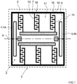
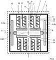
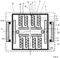
- Figures 1 and 2 each show an embodiment of a capacitive micromechanical sensor structure.
- Figures 3 and 4 are detail views of capacitive micromechanical sensor structures.
- Figures 5 and 6 each show examples of a micromechanical accelerometer each comprising three micromechanical sensors.
- the capacitive micromechanical sensor structure comprises a stator structure 1 rigidly anchored to a substrate 2 and a rotor structure 3 movably anchored by means of spring structures 4; 4a, 4b to the substrate 2.
- the capacitive micromechanical sensor structure may at least partly be fabricated out of a silicon substrate.
- the stator structure 1 has a plurality of stator finger support beams 5.
- the capacitive micromechanical sensor structure has first spaces 6 between two adjacent stator finger support beams 5.
- the rotor structure 3 has a plurality of rotor finger support beams 7.
- the capacitive micromechanical sensor structure has second spaces 8 between two adjacent rotor finger support beams 7.
- the capacitive micromechanical sensor structure, stator finger support beams 5 of the stator structure 1 extend into second spaces 8 of the rotor structure 3 and rotor finger support beams 7 of the rotor structure 3 extend into first spaces 6 of the stator structure 1.
- the capacitive micromechanical sensor structure may have reflectional symmetry with respect to a first central axis A of the capacitive micromechanical sensor structure.
- a stator finger support beam 5 of the stator structure 1 comprises a stator finger structure 9 along at least one side of the stator finger support beam 5.
- the stator finger structure 9 comprises a plurality of stator fingers 10 and stator gaps 11 between two adjacent stator fingers 10.
- the capacitive micromechanical sensor structure may comprise a stator finger support beam 5 of the stator structure 1 comprising a stator finger structure 9 along two opposite sides of the stator finger support beam 5, so that both stator finger structures 9 comprising a plurality of stator fingers 10 and stator gaps 11 between two adjacent stator fingers 10.
- a rotor finger support beam 7 of the rotor structure 3 comprises a rotor finger structure 12 along at least one side of the rotor finger support beam 7.
- the rotor finger structure 12 comprises a plurality of rotor fingers 13 and rotor gaps 14 between two adjacent rotor fingers 13.
- the capacitive micromechanical sensor structure may comprise a rotor finger support beam 7 of the rotor structure 3 comprising a rotor finger structure 12 along two opposites side of the rotor finger support beam 7, so that both rotor finger structures 12 comprising a plurality of rotor fingers 13 and rotor gaps 14 between two adjacent rotor fingers 13.
- Stator fingers 10 along the stator finger structure 9 extend into rotor gaps 14 along the rotor finger structure 12 and rotor fingers 13 along the rotor finger structure 12 extend into stator gaps 11 along the stator finger structure 9.
- Figures 1 to 4 shows examples of capacitive micromechanical sensor structures, where all stator finger support beams 5 are provided with a stator finger structure 9 along a side of the stator finger support beam 5, and where all rotor finger support beams 7 are provided with a rotor finger structure 12 along a side of the rotor finger support beam 7.
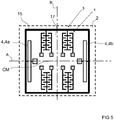
- Figures 5 and 6 shows examples of capacitive micromechanical sensor structures, where all stator finger support beams 5 are provided with a stator finger structure 9 along a side of the stator finger support beam 5, and where all rotor finger support beams 7 are provided with a rotor finger structure 12 along two sides of the rotor finger support beam 7.
- the stator finger support beams of the stator structure and the rotor finger support beams of the rotor structure extend preferably, but not necessarily, perpendicularly with respect to the first central axis A of the capacitive micromechanical sensor structure.
- stator fingers 10 of the stator finger structures 9 of the stator finger support beams 5 of the stator structure 1 extend preferably, but not necessarily, perpendicularly from the stator finger support beams 5, and the rotor fingers 13 of the rotor finger structures 12 of the rotor finger support beams 7 of the rotor structure 3 extend preferably, but not necessarily, perpendicularly from the rotor finger support beams 7, as is the situation in the embodiments shown in figures 1 and 2 .
- the stator fingers of the stator finger structure of the stator finger support beam are preferably, but not necessarily, parallel with the first central axis A of the capacitive micromechanical sensor structure, and the rotor fingers of the rotor finger structure of the rotor finger support beams are preferably, but not necessarily, parallel the first central axis A of the capacitive micromechanical sensor structure.
- the capacitive micromechanical sensor structure may be reflectionally symmetrical with respect to a first central axis A of the capacitive micromechanical sensor structure and be reflectionally symmetrical with respect to a second central axis B of the capacitive micromechanical sensor structure, wherein the first central axis A of the capacitive micromechanical sensor structure and the second central axis B of the capacitive micromechanical sensor structure are perpendicular and cuts each other at a center of mass CM of the capacitive micromechanical sensor structure.
- the stator fingers of the stator finger structure and the rotor fingers of the rotor finger structure are preferably, but not necessarily, parallel with the first central axis A of the capacitive micromechanical sensor structure, and the rotor finger support beams and the stator finger support beams are preferably, but not necessarily, parallel with the second central axis B of the capacitive micromechanical sensor structure.
- the capacitive micromechanical sensor structure comprises preferably, but not necessarily, a rotor frame 15 surrounding the stator structure(s) 1 and the rotor structure(s) 3, as is the situation in the embodiments shown in figures 1 and 2 .
- the rotor frame 15 is movably anchored to the substrate 2 by means of spring structures 4; 4a, 4b, and the rotor finger support beams 7 of the rotor structure 3 are rigidly connected to the rotor frame 15.
- the rotor frame 15 is movably anchored to the substrate 2 by means of spring structures 4; 4a, 4b comprising a first spring structure 4a and a second spring structure 4b.
- the rotor frame 15 is arranged to have reflectional symmetry with respect to the center of mass CM of the capacitive micromechanical sensor structure.
- the rotor frame 15 comprises preferably, but not necessarily, as illustrated in figures 1 and 2 , a first stiff beam (not marked with a reference numeral), a second stiff beam (not marked with a reference numeral), a third stiff beam (not marked with a reference numeral), and a fourth stiff beam (not marked with a reference numeral) rigidly connected to each other at the ends of the stiff beams to form a rectangular-shaped frame.
- the rotor frame 15 is preferably, but not necessarily, as illustrated in figures 1 and 2 , movably anchored to the substrate 2 by means of a first spring structure 4a connected between the middle of the first stiff beam and the substrate 2 and by means of a second spring structure 5a connected between the middle of the second stiff beam that is parallel with the first stiff beam and the substrate 2.
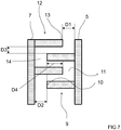
- the rotor structure 3 is preferably, but not necessarily, movably anchored at anchoring points (not marked with a reference numeral) to the substrate 2 by means of spring structures 4; 4a, 4b provided between the rotor structure 3 and the anchoring points in such way that the rotor structure 3 can be deflected at least in a direction parallel with the plane of the substrate 2 with respect to the stator structure 1, which said direction extends preferably, but not necessarily, along a first central axis A of the capacitive micromechanical sensor structure, so that the rotor fingertip gap D1 (see figures 3 and 4 ) between the rotor fingers 13 of the rotor finger structure 12 along the side of the rotor finger support beam 7 and the stator finger support beam 5 changes, and so that the stator fingertip gap D2 (see figures 3 and 4 ) between the stator fingers 10 of the stator finger structure 9 along the side of the stator finger support beam 5 and the rotor finger support beam 7 changes, and so that the finger overlap length D4 (see figures 3
- the rotor frame 15 is movably anchored to the substrate 2 by means of spring structures 4; 4a, 4b comprising a first spring structure 4a and a second spring structure 4b so that the rotor frame 15 can be deflected at least in the direction along the first central axis A with respect to the stator structures 1 and parallel with the plane of the substrate 2 so that the rotor fingertip gap D1 between the rotor fingers 13 of the rotor finger structure 12 along the side of the rotor finger support beam 7 and the stator finger support beam changes, and so that the stator fingertip gap D2 between the stator fingers 10 of the stator finger structure 9 along the side of the stator finger support beam 5 and the rotor finger support beam 7 changes, and so that the finger overlap length D4, which is the length the stator fingers 10 of the stator finger structure 9 extend into the rotor gaps 14 of the rotor finger structure 12, or alternatively which is the length the rotor fingers 13 of the rotor finger structure 12 extend into the stator gaps
- the rotor structure 3 is preferably, but not necessarily, movably anchored to the substrate 2 by means of spring structures 4; 4a, 4b comprising a first spring structure 4a and a second spring structure 4b so that the first spring structure 4a and the second spring structure 4b is arranged at the first central axis A of the capacitive micromechanical sensor structure and symmetrically with respect to the first central axis A of the capacitive micromechanical sensor structure, as is the situation in the embodiments shown in figures 1 and 2 .
- the spring structures 4; 4a, 4b comprise preferably, but not necessarily, at least one of the following: a seesaw type spring structure, an S-shaped spring element, a U-shaped spring element, and a folded spring element.
- the stator finger support beams 5 of the stator finger structure 9 are preferably, but not necessarily, vertical comb electrodes.
- the rotor finger support beams 7 of the rotor finger structure 12 are preferably, but not necessarily, vertical comb electrodes.
- stator fingers 10 of the stator finger support beam(s) 5 of the stator finger structure 9 are preferably, but not necessarily, vertical comb electrodes.
- the rotor fingers 13 of the rotor finger support beam(s) 7 of the rotor finger structure 12 are preferably, but not necessarily, vertical comb electrodes.
- the rotor finger structure 12 along said at least one side of the rotor finger support beam 7 can be designed and dimensioned in such way that the rotor fingers 13 of the rotor finger structure 12 are evenly distributed along said at least one side of the rotor finger support beam 7 and so that the width of the rotor gaps 14 of the rotor finger structure 12 is between 4.5 and 7.5 micrometers, for example 6 micrometers, and so that the width of the rotor fingers 13 of the rotor finger structure 12 is between 1.5 and 2.5 micrometers, for example 2 micrometers.
- the rotor finger structure 12 along said at least one side of the rotor finger support beam 7 can be designed and dimensioned in such way that the rotor fingers 13 of the rotor finger structure 12 have a uniform design and so that the length of the rotor fingers 13 of the rotor finger structure 12 is between 4.0 and 10 micrometers, for example 6 micrometers.
- the stator finger structure 9 along said at least one side of the stator finger support beam 5 can be designed and dimensioned in such way that the stator fingers 10 of the stator finger structure 9 are evenly distributed along said at least one side of the stator finger support beam 5 and so that the width of the stator gaps 11 of the stator finger structure 9 is between 4.5 and 7.5 micrometers and so that the width of the stator fingers 10 of the stator finger structure 9 is between 1.5 and 2.5 micrometers, for example 2 micrometers.
- the stator finger structure 8 along said at least one side of the stator finger support beam 5 can be designed and dimensioned in such way that the stator fingers 10 of the stator finger structure 9 have a uniform design and so that the length of the stator fingers 10 of the stator finger structure 9 is between 4.0 and 10 micrometers, for example 6 micrometers.
- stator fingertip gap D2 (see figures 3 and 4 ) between the stator fingers 10 of the stator finger structure 9 along the side of the stator finger support beam 5 and the rotor finger support beam 7 is preferably, but not necessarily, between 2 and 6 micrometers, and is preferably about 3.5 micrometer.
- the rotor fingertip gap D1 (see figures 3 and 4 ) between the rotor fingers 13 of the rotor finger structure 12 along the side of the rotor finger support beam 7 and the stator finger support beam 5 is preferably, but not necessarily, between 2 and 6 micrometers, and is preferably about 3.5 micrometers.
- the finger side gap D3 (see figures 3 and 4 ) between the stator fingers 10 of the stator finger structure 9 along the side of the stator finger support beam 5 and the rotor fingers 13 of the rotor finger structure 12 along the side of the rotor finger support beam 7 is preferably, but not necessarily, between 1.5 and 2.5 micrometers, and is preferably about 2.0 micrometers.
- the stator fingertip gap D2 (see figures 3 and 4 ) between the stator fingers 10 of the stator finger structure 9 along the side of the stator finger support beam 5 and the rotor finger support beam 7 is preferably, but not necessarily, 1 to 3 times, preferably 1 to 2.5 times, more preferably 1 to 2 times, the finger side gap D3 (see figures 3 and 4 ) between the stator fingers 10 of the stator finger structure 9 along the side of the stator finger support beam 5 and the rotor finger 13 of the rotor finger structure 12 along the side of the rotor finger support beam 7.
- the rotor fingertip gap D1 (see figures 3 and 4 ) between the rotor fingers 13 of the rotor finger structure 12 along the side of the rotor finger support beam 7 and the stator finger support beam 5 is preferably, but not necessarily, 1 to 3 times, preferably 1 to 2.5 times, more preferably 1 to 2 times, the finger side gap D3 (see figures 3 and 4 ) between the stator fingers 10 of the stator finger structure 9 along the side of the stator finger support beam 5 and the rotor fingers 13 of the rotor finger structure 12 along the side of the rotor finger support beam 7.
- the finger overlap length D4 (see figures 3 and 4 ) i.e. the length the stator fingers 10 of the stator finger structure 9 extend into the rotor gaps 14 of the rotor finger structure 12, or alternatively the length the rotor fingers 13 of the rotor finger structure 12 extend into the stator gaps 11 of the stator finger structure 9, is preferably, but not necessarily, between 1 and 4 micrometer, preferably between 2 and 3 micrometer, for example 2 micrometer.
- the finger overlap length D4 is preferably, but not necessarily, selected to be greater than the full-scale deflection of the rotor structure 3. Full-scale deflection meaning the deflection of the rotor structure 3 with maximum sensor acceleration.
- a stator finger support beam 5 of the stator structure 1 comprising a stator finger structure 9 along a side of the stator finger support beam 5 and a rotor finger support beam 7 of the rotor structure 3 comprising a rotor finger structure 12 along a side of the rotor finger support beam 7 may, as in the embodiments shown in figure 1 and 2 , form a comb pair 16.
- the comb structure of the micro-mechanical sensor structure comprises a plurality of such comb pairs 16 and third spaces 17 between two adjacent comb pairs 16.
- the sides of the stator finger support beams 5 that faces the third spaces 17 are preferably, but not necessarily, free of stator fingers 10 such as free from a stator finger structure 9, and the sides of the rotor finger support beams 7 that faces the third spaces 17 are preferably, but not necessarily, free of rotor fingers 13 such as free of a rotor finger structure 12.
- the width of such third spaces 17 is preferably, but not necessarily, between 5 and 10 micrometers, and being preferably about 7.5 micrometers.
- the width of such third spaces 17 capacitive micromechanical sensor structure is preferably, but not necessarily, between 2 to 3 times finger side gap D3 (see figures 3 and 4 ) between the stator fingers 10 of the stator finger structure 9 along the side of the stator finger support beam 5 and the rotor fingers 13 of the rotor finger structure 12 along the side of the rotor finger support beam 7.
- the width of the third spaces 17 capacitive micromechanical sensor structure is preferably, but not necessarily, between 2 to 3 times the distance between the rotor fingers 13 of the rotor finger structure 12 along the rotor finger support beams 7 and a stator finger support beam 5.
- the comb pairs may be grouped in four groups of comb pairs each comprising the same number of comb pairs so that the groups of comb pairs are disposed symmetrically with respect to a first central axis A of the capacitive micromechanical sensor structure and symmetrically with respect to a second central axis B of the capacitive micromechanical sensor structure and symmetrically with respect to the center of mass CM of the capacitive micromechanical sensor structure.
- the capacitive micromechanical sensor structure is preferably, but not necessarily, symmetrical with respect to a first central axis A of the capacitive micromechanical sensor structure and symmetrical with respect to a second central axis B of the capacitive micromechanical sensor structure such that the first central axis A of the capacitive micromechanical sensor structure and the second central axis B of the capacitive micromechanical sensor structure are perpendicular and cuts each other at a center of mass CM of the capacitive micromechanical sensor structure.
- the capacitive micromechanical sensor structure comprises preferably, but not necessarily, as in the embodiments shown in figures 2 , 4 , and 6 , stopper bumps 21 for preventing excess movement of the rotor structure 3 with respect to the stator structure 1 but allowing the rotor structure 3 to move in a direction along the first central axis A a distance corresponding a stopper gap D5 (see figures 2 , 4 , and 6 ) of 1.0 to 2.5 micrometers, preferably 1.5 to 2.0 micrometers.
- stopper bumps 21 A purpose of such stopper bumps 21 is to prevent the rotor structure(s) 3 for adhering to the stator structure(s) 1 and to prevent the rotor structure(s) 3 short-circuiting to the stator structure(s) 1 resulting in that the capacitive micromechanical sensor structure is unable to function. Additionally the stopper bumps 21 can be used to prevent a pull-in effect between the rotor structure(s) 3 and the stator structure(s) 1, in other words to keep the rotor structure(s) 3 at a such distance from the stator structure(s) 1 that no pull-in effect is created between the rotor structure(s) 3 and the stator structure(s) 1.
- the capacitive micromechanical sensor structure may for example as in the embodiments shown in figures 2 , 4 , and 6 comprise a rotor frame 15 surrounding the stator structure 1 and the rotor structure 3, so that the rotor frame 15 is movably anchored to the substrate 2 by means of spring structures 4; 4a, 4b and so that the rotor finger support beams 7 of the rotor structure 3 is rigidly connected to the rotor frame 15 and so that the rotor frame 15 being arranged symmetrically with respect to a center of mass CM of the capacitive micromechanical sensor structure.
- the stopper bumps 21 may be configured to prevent excess movement of the rotor structure 3 with respect to the stator structure 1 by preventing excess movement of the rotor frame 15 with respect to the stator structure 1 but allowing the rotor frame 15 to move in a direction along the first central axis A a distance corresponding a stopper gap D5 (see figures 2 , 4 , and 6 ) of 1.0 to 2.5 micrometers, preferably 1.5 to 2.0 micrometers.
- the capacitive micromechanical sensor structure comprises preferably as in the embodiments shown in figures 2 , 4 , and 6 , stopper bumps 21 for preventing excess movement of the rotor structure 3 with respect to the stator structure 1 but allowing the rotor structure 3 to move in a direction along the first central axis A a distance corresponding a stopper gap D5 that is 0.5 to 1.5, preferably 0.7 to 1 times, the finger side gap D3 between a stator fingers 10 of the stator finger structure 9 along the side of the stator finger support beam 5 and a rotor fingers 13 of the rotor finger structure 12 along the side of the rotor finger support beam 7.
- stopper bumps 21 A purpose of such stopper bumps 21 is to prevent the rotor structure(s) 3 for adhering to the stator structure(s) 1 and to prevent the rotor structure(s) 3 short-circuiting to the stator structure(s) 1 resulting in that the capacitive micromechanical sensor structure is unable to function. Additionally the stopper bumps 21 can be used to prevent a pull-in effect between the rotor structure(s) 3 and the stator structure(s) 1, in other words to keep the rotor structure(s) 3 at a such distance from the stator structure(s) 1 that no pull-in effect is created between the rotor structure(s) 3 and the stator structure(s) 1.
- the capacitive micromechanical sensor structure may for example as in the embodiments shown in figures 2 , 4 , and 6 comprise a rotor frame 15 surrounding the stator structure 1 and the rotor structure 3 so that the rotor frame 15 is movably anchored to the substrate 2 by means of spring structures 4; 4a, 4b and so that the rotor finger support beams 7 of the rotor structure 3 is rigidly connected to the rotor frame 15 and to that the rotor frame 15 is arranged symmetrically with respect to a center of mass CM of the capacitive micromechanical sensor structure.
- the stopper bumps 21 may be configured to prevent excess movement of the rotor structure 3 with respect to the stator structure 1 by preventing excess movement of the rotor frame 15 with respect to the stator structure 1 but allowing the rotor frame 15 to move in a direction along the first central axis A a distance corresponding a stopper gap D5 that is 0.5 to 1.5, preferably 0.7 to 1 times, the finger side gap D3 between a stator fingers 10 of the stator finger structure 9 along the side of the stator finger support beam 5 and a rotor fingers 13 of the rotor finger structure 12 along the side of the rotor finger support beam 7.
- the stopper bumps 21 can for example have a sharp point.
- stopper bumps 21 can for example be provided at any of the following; a rotor frame 21 of the capacitive micromechanical sensor structure, the stator structure 1 of the capacitive micromechanical sensor structure, the rotor structure 2 of the capacitive micromechanical sensor structure, and a separate stopper structure 22, as shown in figures 2 , 4 , and 6 , that is rigidly anchored to the substrate 2.
- micromechanical accelerometer comprising two capacitive micromechanical sensor structures as described earlier and some preferred embodiments and variants of the micromechanical accelerometer will be described in greater detail.
- the micromechanical accelerometer comprising two capacitive micromechanical sensor structures as described earlier comprises a substrate 2 having a plane (not marked with a reference numeral).
- Said two capacitive micromechanical sensor structures forms a first micromechanical sensor 18 and a second micromechanical sensor 19 in the micromechanical accelerometer.
- the first micromechanical sensor 18 is configured for measuring acceleration along an x-axis parallel to the plane of the substrate 2
- the second micromechanical sensor 19 is configured for measuring acceleration along a y-axis parallel to the plane of the substrate 2 and perpendicular to the x-axis.
- the micromechanical accelerometer comprises a third central axis C.
- the first micromechanical sensor 18 is arranged in the micromechanical accelerometer so that the first central axis A1 of the first micromechanical sensor 18 and the third central axis C of the micromechanical accelerometer are parallel.
- the second micromechanical sensor 19 is arranged in the micromechanical accelerometer so that the first central axis A2 of the second micromechanical sensor 19 and the third central axis C of the micromechanical accelerometer are perpendicular.
- the micromechanical accelerometer comprises preferably, but not necessarily, as in the embodiments illustrated in figures 9 to 11 at least one third micromechanical sensor 20 for measuring acceleration along a z-axis perpendicular to the plane of the substrate 2.
- a third micromechanical sensor 20 may, as in the embodiments illustrated in figures 9 to 11 , comprise a comb structure.
Claims (12)
- Kapazitive mikromechanische Sensorstruktur, umfassend:eine Statorstruktur (1), die an einem Substrat (2) starr befestigt ist, und eine Rotorstruktur (3), die mittels einer Federstruktur (4; 4a, 4b) am Substrat (2) beweglich befestigt ist,wobei die Statorstruktur (1) mehrere Statorfinger-Tragbalken (5) aufweist;wobei die Rotorstruktur (3) mehrere Rotorfinger-Tragbalken (7) aufweist,wobei ein Statorfinger-Tragbalken (5) der Statorstruktur (1) eine Statorfingerstruktur (9) entlang mindestens einer Seite des Statorfinger-Tragbalkens (5) umfasst, wobei die Statorfingerstruktur (9) mehrere Statorfinger (10) und Statorzwischenräume (11) zwischen zwei benachbarten Statorfingern (10) umfasst,wobei ein Rotorfinger-Tragbalken (7) der Rotorstruktur (3) eine Rotorfingerstruktur (12) entlang mindestens einer Seite des Rotorfinger-Tragbalkens (7) umfasst, wobei die Rotorfingerstruktur (12) mehrere Rotorfinger (13) und Rotorzwischenräume (14) zwischen zwei benachbarten Rotorfingern (13) umfasst,wobei Statorfinger (10) entlang des Statorfinger-Tragbalkens (5) der Statorstruktur (9) in Rotorzwischenräume (14) entlang des Rotorfinger-Tragbalkens (7) der Rotorstruktur (12) hineinragen,wobei Rotorfinger (13) entlang des Rotorfinger-Tragbalkens (7) der Rotorstruktur (12) in Statorzwischenräume (11) entlang des Statorfinger-Tragbalkens (5) der Statorstruktur (9) hineinragen,wobei die Rotorstruktur (3) beweglich am Substrat (2) befestigt ist, so dass die Rotorstruktur (3) mindestens parallel zur Ebene des Substrats (2) ausgelenkt werden kann, so dass der Rotorfinger-Kopfspalt (D1) zwischen den Rotorfingern (13) entlang mindestens einer Seite des Rotorfinger-Tragbalkens (7) und dem Statorfinger-Tragbalken (5) sich ändert, der Statorfinger-Kopfspalt (D2) zwischen den Statorfingern (10) entlang mindestens einer Seite des Statorfinger-Tragbalkens (5) und dem Rotorfinger-Tragbalken (7) sich ändert und eine Fingerüberlappungslänge (D4) sich ändert, wobei die Fingerüberlappungslänge (D4) die Länge ist, die die Statorfinger (10) der Statorfingerstruktur (9) in die Rotorzwischenräume (14) der Rotorfingerstruktur (12) hineinragen, oder alternativ die Länge ist, die die Rotorfinger (13) der Rotorfingerstruktur (12) in die Statorzwischenräume (11) der Statorfingerstruktur (9) hineinragen, undAnschlagstopper (21) zur Verhinderung einer übermäßigen Bewegung der Rotorstruktur (3) in Bezug auf die Statorstruktur (1), der aber zulässt, dass die Rotorstruktur (3) in zwei entgegengesetzten Richtungen eine einem Stopperspalt (D5) entsprechende Distanz zurücklegen kann, dadurch gekennzeichnet, dass ein Statorfinger-Kopfspalt (D2) zwischen den Statorfingern (10) der Statorfingerstruktur (9) und dem Rotorfinger-Tragbalken (7) im unbelasteten Zustand der kapazitiven mikromechanischen Sensorstruktur 1 bis 2,5 Mal so groß ist wie ein Fingerseitenspalt (D3) zwischen den Statorfingern (10) der Statorfingerstruktur (9) und den Rotorfingern (13) der Rotorfingerstruktur (12), undein Rotorfinger-Kopfspalt (D1) zwischen den Rotorfingern (13) der Rotorfingerstruktur (12) und dem Statorfinger-Tragbalken (5) im unbelasteten Zustand der kapazitiven mikromechanischen Sensorstruktur 1 bis 2,5 Mal so groß ist wie der Fingerseitenspalt (D3) zwischen den Statorfingern (10) der Statorfingerstruktur (9) und den Rotorfingern (13) der Rotorfingerstruktur (12), undder Stopperspalt (D5) 0,25 bis 2,5 Mal so groß ist wie der Fingerseitenspalt (D3) zwischen Statorfingern (10) der Statorfingerstruktur (9) und Rotorfingern (13) der Rotorfingerstruktur (12).
- Kapazitive mikromechanische Sensorstruktur nach Anspruch 1, dadurch gekennzeichnet, dass der Statorfinger-Tragbalken (5) der Statorstruktur (1) eine Statorfingerstruktur (9) entlang zweier entgegengesetzter Seiten des Statorfinger-Tragbalkens (5) umfasst, wobei jede Statorfingerstruktur (9) mehrere Statorfinger (10) und Statorzwischenräume (11) zwischen zwei benachbarten Statorfingern (10) umfasst.
- Kapazitive mikromechanische Sensorstruktur nach Anspruch 1 oder 2, dadurch gekennzeichnet, dass ein Rotorfinger-Tragbalken (7) der Rotorstruktur (3) eine Rotorfingerstruktur (12) entlang zweier entgegengesetzter Seiten des Rotorfinger-Tragbalkens (7) umfasst, wobei jede Rotorfingerstruktur (12) mehrere Rotorfinger (13) und Rotorzwischenräume (14) zwischen zwei benachbarten Rotorfingern (13) umfasst.
- Kapazitive mikromechanische Sensorstruktur nach einem der Ansprüche 1 bis 3, dadurch gekennzeichnet, dass
die Statorfinger (10) der Statorfingerstruktur (9) des Statorfinger-Tragbalkens (5) senkrecht aus dem Statorfinger-Tragbalken (5) herausragen, und
die Rotorfinger (13) der Rotorfingerstruktur (12) der Rotorfinger-Tragbalken (7) senkrecht aus einem Rotorfinger-Tragbalken (7) herausragen. - Kapazitive mikromechanische Sensorstruktur nach Anspruch 4, dadurch gekennzeichnet, dass die Statorfinger-Tragbalken (5) der Statorstruktur (1) und die Rotorfinger-Tragbalken (7) der Rotorstruktur (3) sich senkrecht zur ersten Mittelachse (A) der kapazitiven mikromechanischen Sensorstruktur erstrecken.
- Kapazitive mikromechanische Sensorstruktur nach Anspruch 4, dadurch gekennzeichnet, dass
die Statorfinger (10) der Statorfingerstruktur (9) des Statorfinger-Tragbalkens (5) parallel zur ersten Mittelachse (A) der kapazitiven mikromechanischen Sensorstruktur sind, und
die Rotorfinger (13) der Rotorfingerstruktur (12) der Rotorfinger-Tragbalken (7) parallel zur ersten Mittelachse (A) der kapazitiven mikromechanischen Sensorstruktur sind. - Kapazitive mikromechanische Sensorstruktur nach einem der Ansprüche 5 bis 6, dadurch gekennzeichnet, dass
die Rotorstruktur (3) über Federstrukturen (4; 4a, 4b), die eine erste Federstruktur (4a) und eine zweite Federstruktur (4b) umfassen, beweglich am Substrat (2) befestigt ist, und
die erste Federstruktur (4a) und die zweite Federstruktur (4b) an einer ersten Mittelachse (A) der kapazitiven mikromechanischen Sensorstruktur angeordnet sind, und dergestalt, dass sie in Bezug auf eine zweite Mittelachse (B) der kapazitiven mikromechanischen Sensorstruktur eine Spiegelsymmetrie aufweisen. - Kapazitive mikromechanische Sensorstruktur nach einem der Ansprüche 1 bis 7, dadurch gekennzeichnet, dass
die kapazitive mikromechanische Sensorstruktur einen Rotorrahmen (15) umfasst, der die Statorstruktur (1) und die Rotorstruktur (3) umspannt,
der Rotorrahmen (15) über Federstrukturen (4; 4a, 4b) beweglich am Substrat (2) befestigt ist,
die Rotorfinger-Tragbalken (7) der Rotorstruktur (3) starr mit dem Rotorrahmen (15) verbunden sind, und
der Rotorrahmen (15) in Bezug zu einem Massenschwerpunkt (CM) der kapazitiven mikromechanischen Sensorstruktur symmetrisch angeordnet ist. - Kapazitive mikromechanische Sensorstruktur nach einem der Ansprüche 1 bis 8, gekennzeichnet
dadurch, dass der Statorfinger-Tragbalken (5) eine Statorfingerstruktur (9) entlang einer Seite des Statorfinger-Tragbalkens (5) umfasst und der Rotorfinger-Tragbalken (7) eine Rotorfingerstruktur (12) entlang einer Seite des Rotorfinger-Tragbalkens (7) umfasst, die ein Kammpaar (16) ausbildet,
dadurch, dass die Kammstruktur der kapazitiven mikromechanischen Sensorstruktur mehrere solcher Kammpaare (16) umfasst, und
durch dritte Zwischenräume (17) zwischen zwei benachbarten Kammpaaren (16). - Mikromechanischer Beschleunigungsmesser, der zwei kapazitive mikromechanische Sensorstrukturen nach einem der Ansprüche 1 bis 9 umfasst, dadurch gekennzeichnet, dass
der mikromechanische Beschleunigungsmesser ein Substrat (2) umfasst, das eine Ebene aufweist,
die zwei kapazitiven mikromechanischen Sensorstrukturen einen ersten mikromechanischen Sensor (18) und einen zweiten mikromechanischen Sensor (19) im mikromechanischen Beschleunigungsmesser ausbilden,
der erste mikromechanische Sensor (18) dazu ausgelegt ist, eine Beschleunigung entlang einer x-Achse parallel zur Ebene des Substrats (2) zu messen, und
der zweite mikromechanische Sensor (19) dazu ausgelegt ist, eine Beschleunigung entlang einer y-Achse parallel zur Ebene des Substrats (2) und senkrecht zur x-Achse zu messen. - Mikromechanischer Beschleunigungsmesser nach Anspruch 10, dadurch gekennzeichnet, dass
der mikromechanische Beschleunigungsmesser eine dritte Mittelachse C umfasst,
der erste mikromechanische Sensor (18) im mikromechanischen Beschleunigungsmesser angeordnet ist, so dass eine erste Mittelachse (A1) des ersten mikromechanischen Sensors (18) und die dritte Mittelachse C des mikromechanischen Beschleunigungsmessers parallel sind, und
der zweite mikromechanische Sensor (19) im mikromechanischen Beschleunigungsmesser so angeordnet ist, dass eine erste Mittelachse (A2) des zweiten mikromechanischen Sensors (19) und die dritte Mittelachse C des mikromechanischen Beschleunigungsmessers senkrecht zueinander sind. - Mikromechanischer Beschleunigungsmesser nach Anspruch 10 oder 11, gekennzeichnet durch mindestens einen dritten mikromechanischen Sensor (20) zum Messen einer Beschleunigung entlang einer z-Achse, die senkrecht zur Ebene des Substrats (2) sowie senkrecht zur x-Achse und zur y-Achse steht.
Applications Claiming Priority (2)
| Application Number | Priority Date | Filing Date | Title |
|---|---|---|---|
| FI20135712A FI126199B (en) | 2013-06-28 | 2013-06-28 | CAPACITIVE MICROMECHANICAL SENSOR STRUCTURE AND MICROMECHANICAL ACCELEROMETER |
| PCT/IB2014/062650 WO2014207710A1 (en) | 2013-06-28 | 2014-06-27 | Capacitive micromechanical sensor structure and micromechanical accelerometer |
Publications (2)
| Publication Number | Publication Date |
|---|---|
| EP3014285A1 EP3014285A1 (de) | 2016-05-04 |
| EP3014285B1 true EP3014285B1 (de) | 2019-01-30 |
Family
ID=51383907
Family Applications (1)
| Application Number | Title | Priority Date | Filing Date |
|---|---|---|---|
| EP14753156.0A Active EP3014285B1 (de) | 2013-06-28 | 2014-06-27 | Kapazitive mikromechanische sensorstruktur und mikromechanischer beschleunigungssensor |
Country Status (5)
| Country | Link |
|---|---|
| US (1) | US9547020B2 (de) |
| EP (1) | EP3014285B1 (de) |
| FI (1) | FI126199B (de) |
| TW (1) | TWI570053B (de) |
| WO (1) | WO2014207710A1 (de) |
Families Citing this family (13)
| Publication number | Priority date | Publication date | Assignee | Title |
|---|---|---|---|---|
| FI126199B (en) * | 2013-06-28 | 2016-08-15 | Murata Manufacturing Co | CAPACITIVE MICROMECHANICAL SENSOR STRUCTURE AND MICROMECHANICAL ACCELEROMETER |
| FI127229B (en) | 2015-03-09 | 2018-02-15 | Murata Manufacturing Co | Microelectromechanical structure and device |
| JP6657626B2 (ja) * | 2015-07-10 | 2020-03-04 | セイコーエプソン株式会社 | 物理量センサー、電子機器および移動体 |
| TWI610880B (zh) | 2015-09-22 | 2018-01-11 | 村田製作所股份有限公司 | 半撓性的驗證質量 |
| EP3353557B1 (de) | 2015-09-25 | 2019-07-17 | Murata Manufacturing Co., Ltd. | Verbesserter mikroelektromechanischer beschleunigungsmesser |
| US10352960B1 (en) * | 2015-10-30 | 2019-07-16 | Garmin International, Inc. | Free mass MEMS accelerometer |
| JP2018032848A (ja) * | 2016-08-25 | 2018-03-01 | 株式会社村田製作所 | 半導体装置 |
| CN107064555B (zh) * | 2017-03-10 | 2020-09-04 | 中国科学院地质与地球物理研究所 | 一种mems加速度计及其制造工艺 |
| TWI668412B (zh) * | 2017-05-08 | 2019-08-11 | 日商村田製作所股份有限公司 | 電容式微機電加速度計及相關方法 |
| CN108519498B (zh) * | 2018-03-08 | 2020-09-18 | 北京航天控制仪器研究所 | 一种谐振加速度计的自适应闭环测量系统 |
| CN109490576A (zh) * | 2018-12-19 | 2019-03-19 | 成都力创云科技有限公司 | 一种基于soi的全差分电容式mems加速度计 |
| JP7188311B2 (ja) | 2019-07-31 | 2022-12-13 | セイコーエプソン株式会社 | ジャイロセンサー、電子機器、及び移動体 |
| CN111732070B (zh) * | 2020-06-05 | 2023-01-17 | 东南大学 | 一种pt对称侧动微机电系统 |
Family Cites Families (27)
| Publication number | Priority date | Publication date | Assignee | Title |
|---|---|---|---|---|
| DE19938206A1 (de) * | 1999-08-12 | 2001-02-15 | Bosch Gmbh Robert | Mikromechanischer Drehbeschleunigungssensor |
| US20040231420A1 (en) * | 2003-02-24 | 2004-11-25 | Huikai Xie | Integrated monolithic tri-axial micromachined accelerometer |
| FR2858854B1 (fr) * | 2003-08-13 | 2005-12-16 | Sercel Rech Const Elect | Accelerometre a vibrations parasites reduites par rappel ameliore |
| FR2858853B1 (fr) * | 2003-08-13 | 2006-01-13 | Sercel Rech Const Elect | Accelerometre a vibrations parasites reduites par forme des electrodes amelioree |
| US6910379B2 (en) * | 2003-10-29 | 2005-06-28 | Honeywell International, Inc. | Out-of-plane compensation suspension for an accelerometer |
| US7013730B2 (en) * | 2003-12-15 | 2006-03-21 | Honeywell International, Inc. | Internally shock caged serpentine flexure for micro-machined accelerometer |
| KR100513346B1 (ko) * | 2003-12-20 | 2005-09-07 | 삼성전기주식회사 | 보정전극을 갖는 정전용량형 가속도계 |
| US7279761B2 (en) | 2004-09-15 | 2007-10-09 | The Regents Of The University Of California | Post-release capacitance enhancement in micromachined devices and a method of performing the same |
| FR2880127B1 (fr) * | 2004-12-29 | 2007-03-02 | Commissariat Energie Atomique | Accelerometre micro-usine a peignes capacitifs |
| FR2881568B1 (fr) * | 2005-02-03 | 2011-01-14 | Commissariat Energie Atomique | Condensateur a capacite variable et a forme specifique, gyrometre comportant un tel condensateur et accelerometre comportant un tel condensateur |
| US7258010B2 (en) * | 2005-03-09 | 2007-08-21 | Honeywell International Inc. | MEMS device with thinned comb fingers |
| US7337671B2 (en) * | 2005-06-03 | 2008-03-04 | Georgia Tech Research Corp. | Capacitive microaccelerometers and fabrication methods |
| US7258011B2 (en) * | 2005-11-21 | 2007-08-21 | Invensense Inc. | Multiple axis accelerometer |
| TWI284203B (en) * | 2005-12-23 | 2007-07-21 | Delta Electronics Inc | Accelerometer |
| US7617729B2 (en) * | 2006-02-21 | 2009-11-17 | Physical Logic Ag | Accelerometer |
| DE102006020521A1 (de) | 2006-05-03 | 2007-11-08 | Robert Bosch Gmbh | Anordnung und Verfahren zur Druckmessung |
| KR100899812B1 (ko) * | 2006-12-05 | 2009-05-27 | 한국전자통신연구원 | 정전 용량형 가속도계 |
| DE102006059928A1 (de) * | 2006-12-19 | 2008-08-21 | Robert Bosch Gmbh | Beschleunigungssensor mit Kammelektroden |
| FI122397B (fi) | 2008-04-16 | 2011-12-30 | Vti Technologies Oy | Värähtelevä mikromekaaninen kulmanopeusanturi |
| US8205498B2 (en) * | 2008-11-18 | 2012-06-26 | Industrial Technology Research Institute | Multi-axis capacitive accelerometer |
| US8418555B2 (en) * | 2009-06-26 | 2013-04-16 | Honeywell International Inc. | Bidirectional, out-of-plane, comb drive accelerometer |
| FR2954505B1 (fr) * | 2009-12-22 | 2012-08-03 | Commissariat Energie Atomique | Structure micromecanique comportant une partie mobile presentant des butees pour des deplacements hors plan de la structure et son procede de realisation |
| US8549922B2 (en) * | 2010-03-10 | 2013-10-08 | Taiwan Semiconductor Manufacturing Co., Ltd. | Motion detection using capacitor having different work function materials |
| US9032796B2 (en) * | 2010-04-30 | 2015-05-19 | Qualcomm Mems Technologies, Inc. | Stacked lateral overlap transducer (SLOT) based three-axis accelerometer |
| ITTO20130174A1 (it) * | 2013-03-05 | 2014-09-06 | St Microelectronics Srl | Dispositivo mems e relativa struttura micromeccanica con compensazione integrata delle deformazioni termo-meccaniche |
| FI20135714L (fi) * | 2013-06-28 | 2014-12-29 | Murata Manufacturing Co | Kapasitiivinen mikromekaaninen kiihtyvyysanturi |
| FI126199B (en) * | 2013-06-28 | 2016-08-15 | Murata Manufacturing Co | CAPACITIVE MICROMECHANICAL SENSOR STRUCTURE AND MICROMECHANICAL ACCELEROMETER |
-
2013
- 2013-06-28 FI FI20135712A patent/FI126199B/en active IP Right Grant
-
2014
- 2014-06-24 TW TW103121684A patent/TWI570053B/zh active
- 2014-06-25 US US14/314,243 patent/US9547020B2/en active Active
- 2014-06-27 EP EP14753156.0A patent/EP3014285B1/de active Active
- 2014-06-27 WO PCT/IB2014/062650 patent/WO2014207710A1/en active Application Filing
Non-Patent Citations (1)
| Title |
|---|
| None * |
Also Published As
| Publication number | Publication date |
|---|---|
| US9547020B2 (en) | 2017-01-17 |
| FI126199B (en) | 2016-08-15 |
| TW201524888A (zh) | 2015-07-01 |
| TWI570053B (zh) | 2017-02-11 |
| US20150316581A1 (en) | 2015-11-05 |
| FI20135712A (fi) | 2015-01-07 |
| WO2014207710A1 (en) | 2014-12-31 |
| EP3014285A1 (de) | 2016-05-04 |
Similar Documents
| Publication | Publication Date | Title |
|---|---|---|
| EP3014285B1 (de) | Kapazitive mikromechanische sensorstruktur und mikromechanischer beschleunigungssensor | |
| KR102628619B1 (ko) | 가속도계 | |
| De Laat et al. | A review on in situ stiffness adjustment methods in MEMS | |
| RU2618482C1 (ru) | Датчик ускорения, а также способ изготовления датчика ускорения | |
| US10101357B2 (en) | Accelerometer | |
| EP3268305B1 (de) | Mikroelektromechanische kapazitive sensorstruktur und vorrichtung | |
| US20040182155A1 (en) | Micromachined capacitive lateral accelerometer device and monolithic, three-axis accelerometer having same | |
| US20160356806A1 (en) | Accelerometers | |
| US9476907B2 (en) | Variable capacitance accelerometer with meandering flexures | |
| CN106461701B (zh) | 用于加速度传感器的微机械结构 | |
| US8770043B2 (en) | Comb-structured MEMS accelerometer | |
| CN105452876A (zh) | 电容式微机械加速度传感器 | |
| EP3227691B1 (de) | Mems-sensor und halbleitergehäuse | |
| US9128114B2 (en) | Capacitive sensor device and a method of sensing accelerations | |
| JP2014071097A (ja) | 加速度センサ | |
| Li et al. | A novel sandwich capacitive accelerometer with a double-sided 16-beam-mass structure | |
| JP2004340716A (ja) | 加速度センサ | |
| Kumar et al. | A novel design for enhancing the sensitivity of a capacitive MEMS device | |
| CN106030315B (zh) | 具有框的微机电结构 | |
| RU2377575C2 (ru) | Частотный микромеханический акселерометр | |
| US8966990B2 (en) | MEMS devices exhibiting linear characteristics | |
| Abarca Jiménez et al. | Design considerations and electro-mechanical simulation of an inertial sensor based on a floating gate metal-oxide semiconductor field-effect transistor as transducer | |
| US11852649B2 (en) | Anchor structure for reducing temperature-based error | |
| Du et al. | A micromachined tunable bistable mechanism | |
| RU2442992C1 (ru) | Виброчастотный микромеханический акселерометр |
Legal Events
| Date | Code | Title | Description |
|---|---|---|---|
| PUAI | Public reference made under article 153(3) epc to a published international application that has entered the european phase |
Free format text: ORIGINAL CODE: 0009012 |
|
| 17P | Request for examination filed |
Effective date: 20160126 |
|
| AK | Designated contracting states |
Kind code of ref document: A1 Designated state(s): AL AT BE BG CH CY CZ DE DK EE ES FI FR GB GR HR HU IE IS IT LI LT LU LV MC MK MT NL NO PL PT RO RS SE SI SK SM TR |
|
| AX | Request for extension of the european patent |
Extension state: BA ME |
|
| DAX | Request for extension of the european patent (deleted) | ||
| STAA | Information on the status of an ep patent application or granted ep patent |
Free format text: STATUS: EXAMINATION IS IN PROGRESS |
|
| 17Q | First examination report despatched |
Effective date: 20180405 |
|
| GRAP | Despatch of communication of intention to grant a patent |
Free format text: ORIGINAL CODE: EPIDOSNIGR1 |
|
| STAA | Information on the status of an ep patent application or granted ep patent |
Free format text: STATUS: GRANT OF PATENT IS INTENDED |
|
| INTG | Intention to grant announced |
Effective date: 20180905 |
|
| GRAS | Grant fee paid |
Free format text: ORIGINAL CODE: EPIDOSNIGR3 |
|
| GRAA | (expected) grant |
Free format text: ORIGINAL CODE: 0009210 |
|
| STAA | Information on the status of an ep patent application or granted ep patent |
Free format text: STATUS: THE PATENT HAS BEEN GRANTED |
|
| AK | Designated contracting states |
Kind code of ref document: B1 Designated state(s): AL AT BE BG CH CY CZ DE DK EE ES FI FR GB GR HR HU IE IS IT LI LT LU LV MC MK MT NL NO PL PT RO RS SE SI SK SM TR |
|
| REG | Reference to a national code |
Ref country code: GB Ref legal event code: FG4D |
|
| REG | Reference to a national code |
Ref country code: CH Ref legal event code: EP |
|
| REG | Reference to a national code |
Ref country code: AT Ref legal event code: REF Ref document number: 1093699 Country of ref document: AT Kind code of ref document: T Effective date: 20190215 |
|
| REG | Reference to a national code |
Ref country code: IE Ref legal event code: FG4D |
|
| REG | Reference to a national code |
Ref country code: DE Ref legal event code: R096 Ref document number: 602014040378 Country of ref document: DE |
|
| REG | Reference to a national code |
Ref country code: LT Ref legal event code: MG4D |
|
| REG | Reference to a national code |
Ref country code: NL Ref legal event code: MP Effective date: 20190130 |
|
| PG25 | Lapsed in a contracting state [announced via postgrant information from national office to epo] |
Ref country code: FI Free format text: LAPSE BECAUSE OF FAILURE TO SUBMIT A TRANSLATION OF THE DESCRIPTION OR TO PAY THE FEE WITHIN THE PRESCRIBED TIME-LIMIT Effective date: 20190130 Ref country code: NO Free format text: LAPSE BECAUSE OF FAILURE TO SUBMIT A TRANSLATION OF THE DESCRIPTION OR TO PAY THE FEE WITHIN THE PRESCRIBED TIME-LIMIT Effective date: 20190430 Ref country code: LT Free format text: LAPSE BECAUSE OF FAILURE TO SUBMIT A TRANSLATION OF THE DESCRIPTION OR TO PAY THE FEE WITHIN THE PRESCRIBED TIME-LIMIT Effective date: 20190130 Ref country code: ES Free format text: LAPSE BECAUSE OF FAILURE TO SUBMIT A TRANSLATION OF THE DESCRIPTION OR TO PAY THE FEE WITHIN THE PRESCRIBED TIME-LIMIT Effective date: 20190130 Ref country code: PL Free format text: LAPSE BECAUSE OF FAILURE TO SUBMIT A TRANSLATION OF THE DESCRIPTION OR TO PAY THE FEE WITHIN THE PRESCRIBED TIME-LIMIT Effective date: 20190130 Ref country code: NL Free format text: LAPSE BECAUSE OF FAILURE TO SUBMIT A TRANSLATION OF THE DESCRIPTION OR TO PAY THE FEE WITHIN THE PRESCRIBED TIME-LIMIT Effective date: 20190130 Ref country code: SE Free format text: LAPSE BECAUSE OF FAILURE TO SUBMIT A TRANSLATION OF THE DESCRIPTION OR TO PAY THE FEE WITHIN THE PRESCRIBED TIME-LIMIT Effective date: 20190130 Ref country code: PT Free format text: LAPSE BECAUSE OF FAILURE TO SUBMIT A TRANSLATION OF THE DESCRIPTION OR TO PAY THE FEE WITHIN THE PRESCRIBED TIME-LIMIT Effective date: 20190530 |
|
| REG | Reference to a national code |
Ref country code: AT Ref legal event code: MK05 Ref document number: 1093699 Country of ref document: AT Kind code of ref document: T Effective date: 20190130 |
|
| PG25 | Lapsed in a contracting state [announced via postgrant information from national office to epo] |
Ref country code: RS Free format text: LAPSE BECAUSE OF FAILURE TO SUBMIT A TRANSLATION OF THE DESCRIPTION OR TO PAY THE FEE WITHIN THE PRESCRIBED TIME-LIMIT Effective date: 20190130 Ref country code: LV Free format text: LAPSE BECAUSE OF FAILURE TO SUBMIT A TRANSLATION OF THE DESCRIPTION OR TO PAY THE FEE WITHIN THE PRESCRIBED TIME-LIMIT Effective date: 20190130 Ref country code: BG Free format text: LAPSE BECAUSE OF FAILURE TO SUBMIT A TRANSLATION OF THE DESCRIPTION OR TO PAY THE FEE WITHIN THE PRESCRIBED TIME-LIMIT Effective date: 20190430 Ref country code: IS Free format text: LAPSE BECAUSE OF FAILURE TO SUBMIT A TRANSLATION OF THE DESCRIPTION OR TO PAY THE FEE WITHIN THE PRESCRIBED TIME-LIMIT Effective date: 20190530 Ref country code: GR Free format text: LAPSE BECAUSE OF FAILURE TO SUBMIT A TRANSLATION OF THE DESCRIPTION OR TO PAY THE FEE WITHIN THE PRESCRIBED TIME-LIMIT Effective date: 20190501 Ref country code: HR Free format text: LAPSE BECAUSE OF FAILURE TO SUBMIT A TRANSLATION OF THE DESCRIPTION OR TO PAY THE FEE WITHIN THE PRESCRIBED TIME-LIMIT Effective date: 20190130 |
|
| PG25 | Lapsed in a contracting state [announced via postgrant information from national office to epo] |
Ref country code: EE Free format text: LAPSE BECAUSE OF FAILURE TO SUBMIT A TRANSLATION OF THE DESCRIPTION OR TO PAY THE FEE WITHIN THE PRESCRIBED TIME-LIMIT Effective date: 20190130 Ref country code: DK Free format text: LAPSE BECAUSE OF FAILURE TO SUBMIT A TRANSLATION OF THE DESCRIPTION OR TO PAY THE FEE WITHIN THE PRESCRIBED TIME-LIMIT Effective date: 20190130 Ref country code: SK Free format text: LAPSE BECAUSE OF FAILURE TO SUBMIT A TRANSLATION OF THE DESCRIPTION OR TO PAY THE FEE WITHIN THE PRESCRIBED TIME-LIMIT Effective date: 20190130 Ref country code: AL Free format text: LAPSE BECAUSE OF FAILURE TO SUBMIT A TRANSLATION OF THE DESCRIPTION OR TO PAY THE FEE WITHIN THE PRESCRIBED TIME-LIMIT Effective date: 20190130 Ref country code: CZ Free format text: LAPSE BECAUSE OF FAILURE TO SUBMIT A TRANSLATION OF THE DESCRIPTION OR TO PAY THE FEE WITHIN THE PRESCRIBED TIME-LIMIT Effective date: 20190130 Ref country code: RO Free format text: LAPSE BECAUSE OF FAILURE TO SUBMIT A TRANSLATION OF THE DESCRIPTION OR TO PAY THE FEE WITHIN THE PRESCRIBED TIME-LIMIT Effective date: 20190130 |
|
| REG | Reference to a national code |
Ref country code: DE Ref legal event code: R097 Ref document number: 602014040378 Country of ref document: DE |
|
| PG25 | Lapsed in a contracting state [announced via postgrant information from national office to epo] |
Ref country code: SM Free format text: LAPSE BECAUSE OF FAILURE TO SUBMIT A TRANSLATION OF THE DESCRIPTION OR TO PAY THE FEE WITHIN THE PRESCRIBED TIME-LIMIT Effective date: 20190130 |
|
| PLBE | No opposition filed within time limit |
Free format text: ORIGINAL CODE: 0009261 |
|
| STAA | Information on the status of an ep patent application or granted ep patent |
Free format text: STATUS: NO OPPOSITION FILED WITHIN TIME LIMIT |
|
| PG25 | Lapsed in a contracting state [announced via postgrant information from national office to epo] |
Ref country code: AT Free format text: LAPSE BECAUSE OF FAILURE TO SUBMIT A TRANSLATION OF THE DESCRIPTION OR TO PAY THE FEE WITHIN THE PRESCRIBED TIME-LIMIT Effective date: 20190130 |
|
| 26N | No opposition filed |
Effective date: 20191031 |
|
| PG25 | Lapsed in a contracting state [announced via postgrant information from national office to epo] |
Ref country code: MC Free format text: LAPSE BECAUSE OF FAILURE TO SUBMIT A TRANSLATION OF THE DESCRIPTION OR TO PAY THE FEE WITHIN THE PRESCRIBED TIME-LIMIT Effective date: 20190130 |
|
| REG | Reference to a national code |
Ref country code: CH Ref legal event code: PL |
|
| GBPC | Gb: european patent ceased through non-payment of renewal fee |
Effective date: 20190627 |
|
| PG25 | Lapsed in a contracting state [announced via postgrant information from national office to epo] |
Ref country code: SI Free format text: LAPSE BECAUSE OF FAILURE TO SUBMIT A TRANSLATION OF THE DESCRIPTION OR TO PAY THE FEE WITHIN THE PRESCRIBED TIME-LIMIT Effective date: 20190130 |
|
| REG | Reference to a national code |
Ref country code: BE Ref legal event code: MM Effective date: 20190630 |
|
| PG25 | Lapsed in a contracting state [announced via postgrant information from national office to epo] |
Ref country code: TR Free format text: LAPSE BECAUSE OF FAILURE TO SUBMIT A TRANSLATION OF THE DESCRIPTION OR TO PAY THE FEE WITHIN THE PRESCRIBED TIME-LIMIT Effective date: 20190130 |
|
| PG25 | Lapsed in a contracting state [announced via postgrant information from national office to epo] |
Ref country code: GB Free format text: LAPSE BECAUSE OF NON-PAYMENT OF DUE FEES Effective date: 20190627 Ref country code: IE Free format text: LAPSE BECAUSE OF NON-PAYMENT OF DUE FEES Effective date: 20190627 |
|
| PG25 | Lapsed in a contracting state [announced via postgrant information from national office to epo] |
Ref country code: LU Free format text: LAPSE BECAUSE OF NON-PAYMENT OF DUE FEES Effective date: 20190627 Ref country code: LI Free format text: LAPSE BECAUSE OF NON-PAYMENT OF DUE FEES Effective date: 20190630 Ref country code: BE Free format text: LAPSE BECAUSE OF NON-PAYMENT OF DUE FEES Effective date: 20190630 Ref country code: CH Free format text: LAPSE BECAUSE OF NON-PAYMENT OF DUE FEES Effective date: 20190630 |
|
| PG25 | Lapsed in a contracting state [announced via postgrant information from national office to epo] |
Ref country code: CY Free format text: LAPSE BECAUSE OF FAILURE TO SUBMIT A TRANSLATION OF THE DESCRIPTION OR TO PAY THE FEE WITHIN THE PRESCRIBED TIME-LIMIT Effective date: 20190130 |
|
| PG25 | Lapsed in a contracting state [announced via postgrant information from national office to epo] |
Ref country code: MT Free format text: LAPSE BECAUSE OF FAILURE TO SUBMIT A TRANSLATION OF THE DESCRIPTION OR TO PAY THE FEE WITHIN THE PRESCRIBED TIME-LIMIT Effective date: 20190130 Ref country code: HU Free format text: LAPSE BECAUSE OF FAILURE TO SUBMIT A TRANSLATION OF THE DESCRIPTION OR TO PAY THE FEE WITHIN THE PRESCRIBED TIME-LIMIT; INVALID AB INITIO Effective date: 20140627 |
|
| PG25 | Lapsed in a contracting state [announced via postgrant information from national office to epo] |
Ref country code: MK Free format text: LAPSE BECAUSE OF FAILURE TO SUBMIT A TRANSLATION OF THE DESCRIPTION OR TO PAY THE FEE WITHIN THE PRESCRIBED TIME-LIMIT Effective date: 20190130 |
|
| PGFP | Annual fee paid to national office [announced via postgrant information from national office to epo] |
Ref country code: FR Payment date: 20230628 Year of fee payment: 10 Ref country code: DE Payment date: 20230620 Year of fee payment: 10 |
|
| PGFP | Annual fee paid to national office [announced via postgrant information from national office to epo] |
Ref country code: IT Payment date: 20230623 Year of fee payment: 10 |