EP3266902A1 - Oxidfilmentfernungsverfahren - Google Patents
Oxidfilmentfernungsverfahren Download PDFInfo
- Publication number
- EP3266902A1 EP3266902A1 EP16792573.4A EP16792573A EP3266902A1 EP 3266902 A1 EP3266902 A1 EP 3266902A1 EP 16792573 A EP16792573 A EP 16792573A EP 3266902 A1 EP3266902 A1 EP 3266902A1
- Authority
- EP
- European Patent Office
- Prior art keywords
- oxide film
- oxide
- metal
- superalloy
- removing method
- Prior art date
- Legal status (The legal status is an assumption and is not a legal conclusion. Google has not performed a legal analysis and makes no representation as to the accuracy of the status listed.)
- Granted
Links
Images


Classifications
-
- C—CHEMISTRY; METALLURGY
- C23—COATING METALLIC MATERIAL; COATING MATERIAL WITH METALLIC MATERIAL; CHEMICAL SURFACE TREATMENT; DIFFUSION TREATMENT OF METALLIC MATERIAL; COATING BY VACUUM EVAPORATION, BY SPUTTERING, BY ION IMPLANTATION OR BY CHEMICAL VAPOUR DEPOSITION, IN GENERAL; INHIBITING CORROSION OF METALLIC MATERIAL OR INCRUSTATION IN GENERAL
- C23F—NON-MECHANICAL REMOVAL OF METALLIC MATERIAL FROM SURFACE; INHIBITING CORROSION OF METALLIC MATERIAL OR INCRUSTATION IN GENERAL; MULTI-STEP PROCESSES FOR SURFACE TREATMENT OF METALLIC MATERIAL INVOLVING AT LEAST ONE PROCESS PROVIDED FOR IN CLASS C23 AND AT LEAST ONE PROCESS COVERED BY SUBCLASS C21D OR C22F OR CLASS C25
- C23F1/00—Etching metallic material by chemical means
- C23F1/10—Etching compositions
- C23F1/14—Aqueous compositions
- C23F1/16—Acidic compositions
- C23F1/28—Acidic compositions for etching iron group metals
-
- C—CHEMISTRY; METALLURGY
- C23—COATING METALLIC MATERIAL; COATING MATERIAL WITH METALLIC MATERIAL; CHEMICAL SURFACE TREATMENT; DIFFUSION TREATMENT OF METALLIC MATERIAL; COATING BY VACUUM EVAPORATION, BY SPUTTERING, BY ION IMPLANTATION OR BY CHEMICAL VAPOUR DEPOSITION, IN GENERAL; INHIBITING CORROSION OF METALLIC MATERIAL OR INCRUSTATION IN GENERAL
- C23F—NON-MECHANICAL REMOVAL OF METALLIC MATERIAL FROM SURFACE; INHIBITING CORROSION OF METALLIC MATERIAL OR INCRUSTATION IN GENERAL; MULTI-STEP PROCESSES FOR SURFACE TREATMENT OF METALLIC MATERIAL INVOLVING AT LEAST ONE PROCESS PROVIDED FOR IN CLASS C23 AND AT LEAST ONE PROCESS COVERED BY SUBCLASS C21D OR C22F OR CLASS C25
- C23F1/00—Etching metallic material by chemical means
-
- C—CHEMISTRY; METALLURGY
- C23—COATING METALLIC MATERIAL; COATING MATERIAL WITH METALLIC MATERIAL; CHEMICAL SURFACE TREATMENT; DIFFUSION TREATMENT OF METALLIC MATERIAL; COATING BY VACUUM EVAPORATION, BY SPUTTERING, BY ION IMPLANTATION OR BY CHEMICAL VAPOUR DEPOSITION, IN GENERAL; INHIBITING CORROSION OF METALLIC MATERIAL OR INCRUSTATION IN GENERAL
- C23G—CLEANING OR DE-GREASING OF METALLIC MATERIAL BY CHEMICAL METHODS OTHER THAN ELECTROLYSIS
- C23G1/00—Cleaning or pickling metallic material with solutions or molten salts
- C23G1/02—Cleaning or pickling metallic material with solutions or molten salts with acid solutions
- C23G1/10—Other heavy metals
-
- C—CHEMISTRY; METALLURGY
- C23—COATING METALLIC MATERIAL; COATING MATERIAL WITH METALLIC MATERIAL; CHEMICAL SURFACE TREATMENT; DIFFUSION TREATMENT OF METALLIC MATERIAL; COATING BY VACUUM EVAPORATION, BY SPUTTERING, BY ION IMPLANTATION OR BY CHEMICAL VAPOUR DEPOSITION, IN GENERAL; INHIBITING CORROSION OF METALLIC MATERIAL OR INCRUSTATION IN GENERAL
- C23G—CLEANING OR DE-GREASING OF METALLIC MATERIAL BY CHEMICAL METHODS OTHER THAN ELECTROLYSIS
- C23G1/00—Cleaning or pickling metallic material with solutions or molten salts
- C23G1/02—Cleaning or pickling metallic material with solutions or molten salts with acid solutions
- C23G1/12—Light metals
- C23G1/125—Light metals aluminium
-
- C—CHEMISTRY; METALLURGY
- C23—COATING METALLIC MATERIAL; COATING MATERIAL WITH METALLIC MATERIAL; CHEMICAL SURFACE TREATMENT; DIFFUSION TREATMENT OF METALLIC MATERIAL; COATING BY VACUUM EVAPORATION, BY SPUTTERING, BY ION IMPLANTATION OR BY CHEMICAL VAPOUR DEPOSITION, IN GENERAL; INHIBITING CORROSION OF METALLIC MATERIAL OR INCRUSTATION IN GENERAL
- C23G—CLEANING OR DE-GREASING OF METALLIC MATERIAL BY CHEMICAL METHODS OTHER THAN ELECTROLYSIS
- C23G5/00—Cleaning or de-greasing metallic material by other methods; Apparatus for cleaning or de-greasing metallic material with organic solvents
Definitions
- the present invention relates to an oxide film removing method, and especially, to a method of removing an oxide film formed in a superalloy surface.
- Components of an aircraft engine, a turbine, a plant and so on are sometimes used in a high-temperature environment or a high stress environment. It is known that a part used in the high-temperature environment or the high stress environment is formed of a superalloy material.
- Patent Literature 1 discloses a method of cleaning a metal product.
- the method described in Patent Literature 1 contains removing the surface oxide of the superalloy part by using halide.
- Patent Literature 2 discloses a method of cleaning and repairing a superalloy article.
- the method described in Patent Literature 2 contains reducing an oxide in a crack of the superalloy part by using gaseous active fluoride ions.
- Patent Literature 3 discloses a method in place of fluoride ion cleaning.
- the method described in Patent Literature 3 contains expanding a narrow crack, removing a part of metal oxide with an acid solution, and removing a part of the metal oxide by cleaning in a high-temperature vacuum atmosphere or a high-temperature hydrogen atmosphere.
- An object of the present invention is to provide an oxide film removing method that can effectively remove an oxide film in a superalloy surface without using a highly toxic gaseous fluoride.
- An oxide film removing method in some embodiments is a method of removing an oxide film formed in a surface of a superalloy part that contains a first metal as a base metal and a second metal different from the first metal.
- the oxide film contains oxide of the base metal and oxide of the second metal.
- the oxide film removing method includes arranging the superalloy part inside a heating chamber; preparing a reduction gas atmosphere or a vacuum atmosphere inside the heating chamber; reducing the oxide of the base metal of an oxide film to the base metal by heating the inside of the heating chamber in a condition that the reduction gas atmosphere or the vacuum atmosphere is maintained; and carrying out acid processing to apply acid solution to the superalloy part after the reduction.
- the acid processing includes: dissolving the base metal; and separating the oxide of the second metal left without being reduced through the reduction from the superalloy part together with the dissolved base metal.
- the acid processing may not be carried out before the reduction.
- the base metal may be nickel or cobalt.
- the oxide of the second metal is a metal oxide in which thermodynamic stability is higher than that of the oxide of the base metal.
- the second metal may contain at least one of aluminum, titanium, and chrome.
- the second metal may contain aluminum.
- the acid solution may contain hydrochloric acid.
- the superalloy part may have a crack, and the oxide film may contain an oxide film formed in a surface of the crack.
- the method may not contain expanding a crack physically.
- the method may not contain a fluoride ion cleaning process.
- the oxide film removing method can be provided in which the oxide film in the superalloy surface can be effectively removed without using a highly toxic gaseous fluoride.
- Superalloy means alloy usable (in other words, sustainable in strength) in a high temperature environment (e.g. 800 °C or above).
- a “base metal” means a metal component with the highest content (weight %) of the metal components contained in alloy.
- FIG. 1 is a sectional view schematically showing an example of a superalloy part 1.
- the superalloy part 1 contains a base material 10 and an oxide film 20.
- the oxide film 20 is formed by, for example, exposing the superalloy part 1 to air (oxygen) under the high-temperature environment. Note that a boundary between the base material 10 and the oxide film 20 is clearly illustrated in FIG. 1 . However, in actual, the boundary between the base material 10 and the oxide film is not always definite.
- the base material 10 is superalloy that contains base metal and second metal.
- the base metal is nickel and the second metal is aluminum.
- the oxide film 20 contains the oxide of base metal and the oxide of second metal.
- the oxide of base metal is nickel oxide (e.g. NiO).
- the oxide of second metal is aluminum oxide (e.g. Al 2 O 3 ).
- a region 22 where nickel oxide is rich is schematically shown by a symbol of a white triangle.
- a region 24 where aluminum oxide is rich is schematically shown by a symbol of a white circle.
- FIG. 2 is a sectional view schematically showing the superalloy part 1 after nickel oxide is reduced to nickel.
- FIG. 2 a region 32 where nickel has become rich through the reduction is schematically shown by a symbol of black triangle. Note that although not illustrated to FIG. 2 , nickel oxide that exists in the region 24 where aluminum oxide is rich has also been reduced to nickel.
- aluminum oxide is a compound that is stable thermodynamically, the state of oxide is maintained even if the aluminum oxide is arranged in the high-temperature reduction gas atmosphere or the high-temperature vacuum atmosphere. Therefore, the aluminum oxide is difficult to be reduced more than the nickel oxide.
- the region 32 where nickel is rich is dissolved with the hydrochloric acid solution (more specifically, nickel in the region where nickel is rich is dissolved by the hydrochloric acid solution). Also, the hydrochloric acid solution enters a cavity (or a passage) formed through the dissolving of nickel. As a result, nickel in a region other than the region 32 where nickel is rich (for example, nickel in the region 24 where aluminum oxide is rich) is also dissolved by the hydrochloric acid solution.
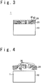
- FIG. 3 is a sectional view schematically showing the superalloy part 1 during application of the hydrochloric acid solution.
- the region 32 where nickel is rich disappears through the dissolution and a cavity 42 (or a passage) is formed.
- a smaller cavity 43 is formed from the cavity 42. Due to existence of the cavity 42 and the cavity 43, bonding force between a portion of the oxide film 20 and another portion of the oxide film 20, and bonding force between the oxide film 20 and the base material 10 are reduced.
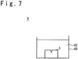
- FIG. 4 is a sectional view schematically showing the superalloy part 1 during the application of hydrochloric acid solution, and showing the state after a time passed from the state shown in FIG. 3 .
- the aluminum oxide or the region 24 where aluminum oxide is rich
- the superalloy part 1 or the base material 10
- the dissolved nickel due to the reduction of bonding force between the oxide film 20 and the base material 10.
- the cavity 42 or cavity 43 as shown in FIG. 3 is difficult to be formed, since the nickel oxide is difficult to be dissolved with the hydrochloric acid solution more than nickel.
- the oxide of base metal is reduced to the base metal before the application of hydrochloric acid solution, the cavity 42 or cavity 43 as shown in FIG. 3 is easy to be formed.
- the aluminum oxide that is difficult to be reduced becomes able to be separated from the superalloy part 1 (or the base material 10).
- the base metal is nickel
- the base metal is not limited to nickel.
- the base metal may be cobalt.
- the second metal contained in the superalloy part 1 is aluminum has been described.
- the second metal is not limited to aluminum.
- the second metal may be chrome or titanium.
- the second metal may contain at least one of aluminum, titanium, and chrome.
- the second metal may contain aluminum and chrome.
- the acid solution is hydrochloric acid solution.
- the acid solution is not limited to the hydrochloric acid solution, and is optional.
- the acid solution may be an acid solution of whatever kind if the acid solution can dissolve the base metal.
- the acid solution may be mixed acid (for example, the mixed acid of hydrochloric acid and nitric acid).
- FIG. 5 is a sectional view schematically showing an example of the superalloy part 1.
- the oxide film 20 is formed in the surface of the superalloy part 1.
- the oxide film 20 may be formed in the whole surface of the superalloy part 1 and may be formed in a part of the surface of the superalloy part 1.
- the superalloy part 1 is a superalloy part that has a crack 3.
- the oxide film 20 is formed in the surface of crack 3, too.
- the base metal of the superalloy part 1 is nickel.
- a first metal with the highest content weight% is, for example, nickel.
- the superalloy part 1 may be a nickel-based superalloy part (in other words, the superalloy part in which the content of the nickel is 50 weight% or above).
- aluminum may be contained as the alloy component in the superalloy part 1.
- the second metal that is different from the first metal is, for example, aluminum.
- the oxide of base metal (e.g. nickel) and the oxide of second metal (e.g. aluminum) are contained in the oxide film in the surface of superalloy part 1.
- FIG. 6 is a sectional view schematically showing an example of the reduction processing device 5.
- the reduction processing device 5 includes, for example, a main unit section 51, a door 52, a heater 53, a temperature sensor 54, a controller 55, a gas supply pipe 56, a first valve 57, a gas discharge pipe 58, and a second valve 59.
- the main unit section 51 accommodates the superalloy part 1 as an object to be processed.
- the door 52 opens and closes an opening of the main unit section 51.
- the main unit section 51 and the door 52 functions as a heating chamber 50 when the superalloy part 1 is to be reduction processed (more specifically, a heating sealed chamber).
- the heater 53 is a device for heating the heating chamber 50.
- the heater 53 is a device for heating the heating chamber or the superalloy part 1 arranged in the heating chamber.
- the temperature sensor 54 is a sensor to measure a temperature in the heating chamber or a temperature of the superalloy part 1. Data acquired by the temperature sensor 54 is sent to the controller 55.
- the controller 55 controls the heater 53 based on the data received from the temperature sensor 54. By controlling the heater 53 by the controller 55, the temperature in the heating chamber or the temperature of the superalloy part 1 is maintained in a desired temperature.
- the gas supply pipe 56 is used to supply reduction gas into the heating chamber 50.
- the first valve 57 is arranged in the passage of gas supply pipe 56 and opens and closes the passage.
- the reduction gas is hydrogen gas. Note that when the reduction processing device 5 is a device which carries out the reduction processing in a vacuum atmosphere, the gas supply pipe 56 and the first valve 57 may be omitted.
- the gas discharge pipe 58 is used to discharge air (gas) from the heating chamber 50.
- the gas discharge pipe 58 is connected with a vacuum pump (not illustrated).
- the second valve 59 is arranged in the passage of gas discharge pipe 58 and opens and closes the passage.
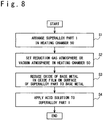
- FIG. 7 is a sectional view schematically showing an example of the acid processing device 6.
- the acid processing device 6 has a liquid bath 60.
- Acid solution 62 is filled in the liquid bath 60.
- the superalloy part 1 as the object to be processed is arranged in the liquid bath 60.
- FIG. 8 is a flow chart showing the procedure of removing the oxide film.
- the superalloy part 1 that contains nickel (first metal) as the base metal and aluminum (second metal different from nickel) is arranged in the heating chamber 50.
- the oxide film 20 is formed in the surface of the superalloy part 1. Also, the oxide film 20 contains nickel oxide (the oxide of base metal) and aluminum oxide (the oxide of second metal).
- a reduction gas atmosphere or a vacuum atmosphere is prepared in the heating chamber 50.
- the gas in the heating chamber 50 is first discharged through the gas discharge pipe 58. After that, the reduction gas is supplied into the heating chamber 50 through the gas supply pipe 56.
- the reduction gas is hydrogen (H 2 ) gas.
- the grade of hydrogen gas to be supplied into the heating chamber 50 is, for example, G1 equivalent (in other words, the purity of hydrogen gas is 99.99999 volume % or above).
- the reduction gas is the hydrogen gas, for example, the dew point in the heating chamber 50 after introduction of the reduction gas is equal to or less than -80 °C.
- the gas in the heating chamber 50 is discharged through the gas discharge pipe 58.
- the pressure in the heating chamber 50 is lowered to 10 -3 Pa or below.
- a third step S3 is a reduction step of reducing the oxide of base metal to the base metal.
- the inside of the heating chamber 50 is heated in the condition that the reduction gas atmosphere or the vacuum atmosphere is maintained.
- the temperature in the heating chamber is maintained at, for example, 800 °C or above, 1000 °C or above, 1100 °C or above (especially, in case of the vacuum atmosphere), or 1200 °C or above.
- the temperature in the heating chamber is maintained below the melting point of superalloy that configures the superalloy part.
- the heating processing time is, for example, from 15 minutes to 24 hours, from 30 minutes to 24 hours, or from 60 minutes to 24 hours.
- the temperature in the heating chamber is 1000 °C or above and the melting point of superalloy or below, and the heating processing time is from 30 minutes or above to 300 minutes or below.
- the third step S3 As the reduction step, nickel oxide (the oxide of base metal) is reduced to nickel (the base metal) of the oxide contained in the surface oxide film of the superalloy part 1.
- the superalloy part 1 is taken out from the heating chamber 50.
- a fourth step S4 is an acid processing step.
- the acid solution is applied to the superalloy part 1.
- the application of acid solution to the superalloy part 1 is carried out by, for example, immersing the superalloy part 1 in the acid solution 62 in the liquid bath 60.
- the acid solution contains hydrochloric acid. This is because nickel has a high solubility to the hydrochloric acid.
- Iron chloride (III) FeCl 3
- Iron chloride (III) reinforces oxidizability of the hydrochloric acid.
- nitric acid may be contained in the acid solution.
- the acid solution may be a solution that contains the hydrochloric acid, the iron chloride (III) and the nitric acid.
- the temperature of acid solution is, for example, 10 °C or above and 40 °C or below, 10 °C or above and 30 °C or below, or 20 °C or above and 30 °C or below.
- the processing time of the acid processing step (in other words, a time during which the superalloy part 1 is immersed in the acid solution) is, for example, 20 minutes or above to 180 minutes or below, 30 minutes or above to 180 minutes or below, 40 minutes or above to 180 minutes or below.
- nickel (the base metal) that exists in the surface of the superalloy part 1 is dissolved by the acid solution.
- nickel (the base metal) generated from nickel oxide (the oxide of base metal) in the oxide film 20 by the reduction step is dissolved by the acid solution.
- the aluminum oxide (the oxide of second metal) left without being reduced at the reduction step is separated from the superalloy part 1 together with the dissolved base metal.
- the superalloy part 1 is taken out from the acid solution and washed (e.g. with water).
- the oxide film 20 is effectively removed from the superalloy part 1 through the above steps.
- the superalloy part 1 processed by the above steps is a superalloy part having a crack 3.
- the oxide film 20 is formed in the surface of the crack 3, too.
- a physical method such as polishing cannot be sometimes applied.
- the oxide film removing method in the present embodiment is effective.
- a step of physically expanding the crack 3 by the polishing and so on is unnecessary.
- the crack 3 may be repaired, after the oxide film removing method in the present embodiment is executed (in other words, after execution the above-mentioned first to fourth steps).
- the repair of the crack 3 is executed by filling a brazing material into the crack 3.
- the brazing material the brazing material having the base metal of the superalloy part 1 as a main component can be used.
- the base metal of the superalloy part 1 is nickel, nickel-based brazing material is used, and when the base metal of the superalloy part 1 is cobalt, cobalt-based brazing material can be used.
- the superalloy part 1 may be a superalloy part which has been used in the high-temperature environment of equal to or more than 800 °C.
- the crack and so on is easy to be caused due to heat fatigue in the superalloy part which has been used in the high-temperature environment.
- the oxide film in the surface of the superalloy part has a low solubility to the acid solution due to the exposure to the high-temperature environment. Therefore, it is sometimes difficult to remove the oxide film only by the acid processing. In such a case, the oxide film removing method in the present embodiment is effective.
- Aluminum oxide, titanium oxide or chrome oxide may be contained in the oxide film 20 in the surface of the superalloy part 1.
- the aluminum oxide, the titanium oxide and the chrome oxide are oxides difficult to reduce, compared with the nickel oxide.
- the aluminum oxide, the titanium oxide and the chrome oxide are not reduced by the reduction step of the above-mentioned third step. Therefore, when the aluminum oxide, the titanium oxide or the chrome oxide is contained in the oxide film 20 in the surface of the superalloy part 1, the oxide film removing method in the present embodiment is effective in which the acid processing step is executed after the reduction step.
- thermodynamic stability of the metal oxide is Al 2 O 3 > TiO 2 > Cr 2 O 3 > CoO > NiO in descending order at 1200 °C. Therefore, generally, the reduction is difficult in the order of the aluminum oxide, the titanium oxide, the chrome oxide, the cobalt oxide, and the nickel oxide.
- the strong reducer of gaseous fluoride e.g. HF gas
- the gaseous fluoride has high toxicity.
- the gaseous fluoride sometimes gives damage to the boundary between crystals of the superalloy.
- the superalloy part sometimes corrodes due to the gaseous fluoride remained after reduction processing.
- a special facility is necessary for the application of the gaseous fluoride.
- the oxide film removing method in the present embodiment it is possible to remove the aluminum oxide and so on without reducing it. For this reason, it is possible to avoid and reduce the use of the strong reducer such as the gaseous fluoride.
- FIG. 9A to FIG. 9C are experiment data showing the effectivity of the oxide film removing method in the present embodiment.
- FIG. 9A is a graph showing the analysis result.
- the horizontal axis shows a depth (nanometer) from the surface of the superalloy sample, and the vertical axis shows detection strength (the number of detected photoelectrons).
- nickel oxide, aluminum oxide and chrome oxide are formed in the surface of the superalloy sample (the region from 0 nm to 1600 nm in depth from the surface of the sample). Also, it could be found that metal nickel exists hardly in the region from 0 nm to 800 nm in depth from the surface of the sample.
- FIG. 9B is a graph showing the analysis result.
- the horizontal axis shows a depth (nanometer) from the surface of the superalloy sample
- the vertical axis shows detection strength (the number of detected photoelectrons).
- metal nickel exists in the region from 0 nm to 800 nm in depth from the surface of the sample.
- the nickel oxide existing in the region from 0 nm to 800 nm in depth from the surface of the sample was reduced to metal nickel.
- nickel oxide since nickel oxide was hardly observed in the region from 800 nm to 1600 nm in depth from the surface of the sample, the nickel oxide that had existed in the region from 800 nm to 1600 nm in depth from the surface of the sample has also been reduced to metal nickel.
- the nickel oxide which is the oxide of base metal was effectively reduced but aluminum oxide and chrome oxide were not effectively reduced.
- FIG. 9C is a graph showing the analysis result.
- the horizontal axis shows a depth (nanometer) from the surface of the superalloy sample, and the vertical axis shows detection strength (the number of detected photoelectrons).
- the oxide film was formed when the superalloy part was exposed to air (oxygen) under the high-temperature environment.
- the oxide film becomes difficult to dissolve by the acid when the oxide film is exposed to air in the high-temperature environment. Therefore, it is desirable that the reduction processing is executed before the acid processing, in order to remove the oxide film effectively.
- the reduction processing is executed before the acid processing. Therefore, in some embodiments, the oxide film can be removed more effectively, compared with a case of execute the reduction processing after the acid processing.
- the present invention is not limited to the above embodiments, and it would be apparent that the embodiments may be changed or modified appropriately in a range of the technique thought of the present invention. Also, various techniques used in each of the embodiments or modification examples can be applied to another embodiment or modification example, as long as any technical contradiction does not occur.
Landscapes
- Chemical & Material Sciences (AREA)
- Chemical Kinetics & Catalysis (AREA)
- General Chemical & Material Sciences (AREA)
- Engineering & Computer Science (AREA)
- Materials Engineering (AREA)
- Mechanical Engineering (AREA)
- Metallurgy (AREA)
- Organic Chemistry (AREA)
- Cleaning And De-Greasing Of Metallic Materials By Chemical Methods (AREA)
- ing And Chemical Polishing (AREA)
Applications Claiming Priority (2)
| Application Number | Priority Date | Filing Date | Title |
|---|---|---|---|
| JP2015096027A JP6508823B2 (ja) | 2015-05-08 | 2015-05-08 | 酸化膜除去方法 |
| PCT/JP2016/063267 WO2016181848A1 (ja) | 2015-05-08 | 2016-04-27 | 酸化膜除去方法 |
Publications (3)
| Publication Number | Publication Date |
|---|---|
| EP3266902A1 true EP3266902A1 (de) | 2018-01-10 |
| EP3266902A4 EP3266902A4 (de) | 2018-02-14 |
| EP3266902B1 EP3266902B1 (de) | 2020-01-01 |
Family
ID=57249001
Family Applications (1)
| Application Number | Title | Priority Date | Filing Date |
|---|---|---|---|
| EP16792573.4A Active EP3266902B1 (de) | 2015-05-08 | 2016-04-27 | Oxidfilmentfernungsverfahren |
Country Status (6)
| Country | Link |
|---|---|
| US (1) | US20180135186A1 (de) |
| EP (1) | EP3266902B1 (de) |
| JP (1) | JP6508823B2 (de) |
| CA (1) | CA2982720C (de) |
| ES (1) | ES2773110T3 (de) |
| WO (1) | WO2016181848A1 (de) |
Families Citing this family (1)
| Publication number | Priority date | Publication date | Assignee | Title |
|---|---|---|---|---|
| JP6408053B2 (ja) * | 2017-03-21 | 2018-10-17 | 株式会社東芝 | ニッケル基合金除染方法 |
Family Cites Families (10)
| Publication number | Priority date | Publication date | Assignee | Title |
|---|---|---|---|---|
| GB1313545A (en) * | 1969-09-09 | 1973-04-11 | Antonsteel Pty Ltd | Processing of scrap metal |
| US4188237A (en) * | 1978-02-02 | 1980-02-12 | University Of Dayton | Method for cleaning metal parts with elemental fluorine |
| US4405379A (en) * | 1980-02-06 | 1983-09-20 | University Of Dayton | Method for cleaning metal parts |
| US4729799A (en) * | 1986-06-30 | 1988-03-08 | United Technologies Corporation | Stress relief of single crystal superalloy articles |
| CH674851A5 (de) * | 1987-12-01 | 1990-07-31 | Bbc Brown Boveri & Cie | |
| JPH07290280A (ja) * | 1994-04-26 | 1995-11-07 | Nippon Steel Corp | ハステロイ系tig溶接ワイヤの製造方法 |
| JP2002146449A (ja) * | 2000-11-02 | 2002-05-22 | Toyota Motor Corp | 水素吸蔵合金の再生方法 |
| US20050035085A1 (en) * | 2003-08-13 | 2005-02-17 | Stowell William Randolph | Apparatus and method for reducing metal oxides on superalloy articles |
| EP1559485A1 (de) * | 2004-01-30 | 2005-08-03 | Siemens Aktiengesellschaft | Verfahren zur Entfernung einer Schicht |
| US20110120972A1 (en) * | 2009-11-20 | 2011-05-26 | Meyer Tool, Inc. | Replacement process for fluoride ion cleaning |
-
2015
- 2015-05-08 JP JP2015096027A patent/JP6508823B2/ja active Active
-
2016
- 2016-04-27 US US15/572,368 patent/US20180135186A1/en not_active Abandoned
- 2016-04-27 CA CA2982720A patent/CA2982720C/en active Active
- 2016-04-27 ES ES16792573T patent/ES2773110T3/es active Active
- 2016-04-27 WO PCT/JP2016/063267 patent/WO2016181848A1/ja not_active Ceased
- 2016-04-27 EP EP16792573.4A patent/EP3266902B1/de active Active
Also Published As
| Publication number | Publication date |
|---|---|
| CA2982720A1 (en) | 2016-11-17 |
| CA2982720C (en) | 2020-07-21 |
| EP3266902A4 (de) | 2018-02-14 |
| EP3266902B1 (de) | 2020-01-01 |
| US20180135186A1 (en) | 2018-05-17 |
| WO2016181848A1 (ja) | 2016-11-17 |
| ES2773110T3 (es) | 2020-07-09 |
| JP2016211039A (ja) | 2016-12-15 |
| JP6508823B2 (ja) | 2019-05-08 |
Similar Documents
| Publication | Publication Date | Title |
|---|---|---|
| JP6312157B2 (ja) | ニッケル基超合金のための溶接前熱処理 | |
| CN106163717A (zh) | 利用等静压固溶处理的超级合金部件钎焊修复 | |
| EP2022868A2 (de) | Verfahren zur Herstellung einer Platin-Aluminid-Beschichtung | |
| US7761989B2 (en) | Methods for repairing gas turbine engine components | |
| Nowak et al. | Effect of TIG welding and rare earth elements alloying on corrosion resistance of magnesium alloys | |
| CN104703687A (zh) | 表面氧化物的去除方法 | |
| Murakami et al. | Anisotropy of secondary reaction zone formation in aluminized Ni-based single-crystal superalloys | |
| US20110120972A1 (en) | Replacement process for fluoride ion cleaning | |
| EP3266902B1 (de) | Oxidfilmentfernungsverfahren | |
| JP2005539139A (ja) | ニッケル超合金のための性質回復方法 | |
| US7146990B1 (en) | Process for repairing sulfidation damaged turbine components | |
| US11235405B2 (en) | Method of repairing superalloy components using phase agglomeration | |
| US9103037B2 (en) | Method for stripping gamma-gamma prime coating from gamma-gamma prime alloy | |
| EP2821526B1 (de) | Verfahren zur Schmutzbeseitigung beim Abziehen einer Beschichtung | |
| EP2562292B1 (de) | Chemische Strippzusammensetzung und Verfahren | |
| EP2022869A2 (de) | Verfahren zum Formen von Aluminiddiffusionsbeschichtungen aktiver Elemente | |
| US20140356186A1 (en) | Method for Manufacturing Gas Turbine Blade, and Gas Turbine Blade | |
| KR101389020B1 (ko) | Ti-Nb-X계 타이타늄 합금의 에칭방법 | |
| EP1990445A1 (de) | Verfahren zur Entfernung von auf Karbid basierenden Schutzschichten | |
| Kasai et al. | Effect of thermal history on microstructural changes in aluminized nickel-based single-crystal superalloy | |
| US9822456B2 (en) | Method and apparatus for removing oxide from metallic substrate | |
| Kim et al. | The microstructural analysis of the effect of FIC on gas turbine blades | |
| WO2018191861A1 (en) | Method for removing oxide materials from a crack |
Legal Events
| Date | Code | Title | Description |
|---|---|---|---|
| STAA | Information on the status of an ep patent application or granted ep patent |
Free format text: STATUS: THE INTERNATIONAL PUBLICATION HAS BEEN MADE |
|
| PUAI | Public reference made under article 153(3) epc to a published international application that has entered the european phase |
Free format text: ORIGINAL CODE: 0009012 |
|
| STAA | Information on the status of an ep patent application or granted ep patent |
Free format text: STATUS: REQUEST FOR EXAMINATION WAS MADE |
|
| 17P | Request for examination filed |
Effective date: 20171005 |
|
| AK | Designated contracting states |
Kind code of ref document: A1 Designated state(s): AL AT BE BG CH CY CZ DE DK EE ES FI FR GB GR HR HU IE IS IT LI LT LU LV MC MK MT NL NO PL PT RO RS SE SI SK SM TR |
|
| AX | Request for extension of the european patent |
Extension state: BA ME |
|
| A4 | Supplementary search report drawn up and despatched |
Effective date: 20180115 |
|
| RIC1 | Information provided on ipc code assigned before grant |
Ipc: C23G 5/00 20060101AFI20180109BHEP Ipc: C23F 1/28 20060101ALI20180109BHEP Ipc: C23F 1/00 20060101ALI20180109BHEP |
|
| DAV | Request for validation of the european patent (deleted) | ||
| DAX | Request for extension of the european patent (deleted) | ||
| RAP1 | Party data changed (applicant data changed or rights of an application transferred) |
Owner name: MITSUBISHI HEAVY INDUSTRIES AERO ENGINES, LTD. |
|
| GRAP | Despatch of communication of intention to grant a patent |
Free format text: ORIGINAL CODE: EPIDOSNIGR1 |
|
| STAA | Information on the status of an ep patent application or granted ep patent |
Free format text: STATUS: GRANT OF PATENT IS INTENDED |
|
| INTG | Intention to grant announced |
Effective date: 20190711 |
|
| GRAS | Grant fee paid |
Free format text: ORIGINAL CODE: EPIDOSNIGR3 |
|
| GRAA | (expected) grant |
Free format text: ORIGINAL CODE: 0009210 |
|
| STAA | Information on the status of an ep patent application or granted ep patent |
Free format text: STATUS: THE PATENT HAS BEEN GRANTED |
|
| AK | Designated contracting states |
Kind code of ref document: B1 Designated state(s): AL AT BE BG CH CY CZ DE DK EE ES FI FR GB GR HR HU IE IS IT LI LT LU LV MC MK MT NL NO PL PT RO RS SE SI SK SM TR |
|
| REG | Reference to a national code |
Ref country code: GB Ref legal event code: FG4D |
|
| REG | Reference to a national code |
Ref country code: CH Ref legal event code: EP Ref country code: AT Ref legal event code: REF Ref document number: 1219867 Country of ref document: AT Kind code of ref document: T Effective date: 20200115 |
|
| REG | Reference to a national code |
Ref country code: IE Ref legal event code: FG4D |
|
| REG | Reference to a national code |
Ref country code: DE Ref legal event code: R096 Ref document number: 602016027442 Country of ref document: DE |
|
| REG | Reference to a national code |
Ref country code: NL Ref legal event code: MP Effective date: 20200101 |
|
| REG | Reference to a national code |
Ref country code: ES Ref legal event code: FG2A Ref document number: 2773110 Country of ref document: ES Kind code of ref document: T3 Effective date: 20200709 |
|
| REG | Reference to a national code |
Ref country code: LT Ref legal event code: MG4D |
|
| PG25 | Lapsed in a contracting state [announced via postgrant information from national office to epo] |
Ref country code: NL Free format text: LAPSE BECAUSE OF FAILURE TO SUBMIT A TRANSLATION OF THE DESCRIPTION OR TO PAY THE FEE WITHIN THE PRESCRIBED TIME-LIMIT Effective date: 20200101 Ref country code: LT Free format text: LAPSE BECAUSE OF FAILURE TO SUBMIT A TRANSLATION OF THE DESCRIPTION OR TO PAY THE FEE WITHIN THE PRESCRIBED TIME-LIMIT Effective date: 20200101 Ref country code: RS Free format text: LAPSE BECAUSE OF FAILURE TO SUBMIT A TRANSLATION OF THE DESCRIPTION OR TO PAY THE FEE WITHIN THE PRESCRIBED TIME-LIMIT Effective date: 20200101 Ref country code: FI Free format text: LAPSE BECAUSE OF FAILURE TO SUBMIT A TRANSLATION OF THE DESCRIPTION OR TO PAY THE FEE WITHIN THE PRESCRIBED TIME-LIMIT Effective date: 20200101 Ref country code: NO Free format text: LAPSE BECAUSE OF FAILURE TO SUBMIT A TRANSLATION OF THE DESCRIPTION OR TO PAY THE FEE WITHIN THE PRESCRIBED TIME-LIMIT Effective date: 20200401 Ref country code: CZ Free format text: LAPSE BECAUSE OF FAILURE TO SUBMIT A TRANSLATION OF THE DESCRIPTION OR TO PAY THE FEE WITHIN THE PRESCRIBED TIME-LIMIT Effective date: 20200101 Ref country code: PT Free format text: LAPSE BECAUSE OF FAILURE TO SUBMIT A TRANSLATION OF THE DESCRIPTION OR TO PAY THE FEE WITHIN THE PRESCRIBED TIME-LIMIT Effective date: 20200527 |
|
| PG25 | Lapsed in a contracting state [announced via postgrant information from national office to epo] |
Ref country code: LV Free format text: LAPSE BECAUSE OF FAILURE TO SUBMIT A TRANSLATION OF THE DESCRIPTION OR TO PAY THE FEE WITHIN THE PRESCRIBED TIME-LIMIT Effective date: 20200101 Ref country code: SE Free format text: LAPSE BECAUSE OF FAILURE TO SUBMIT A TRANSLATION OF THE DESCRIPTION OR TO PAY THE FEE WITHIN THE PRESCRIBED TIME-LIMIT Effective date: 20200101 Ref country code: HR Free format text: LAPSE BECAUSE OF FAILURE TO SUBMIT A TRANSLATION OF THE DESCRIPTION OR TO PAY THE FEE WITHIN THE PRESCRIBED TIME-LIMIT Effective date: 20200101 Ref country code: GR Free format text: LAPSE BECAUSE OF FAILURE TO SUBMIT A TRANSLATION OF THE DESCRIPTION OR TO PAY THE FEE WITHIN THE PRESCRIBED TIME-LIMIT Effective date: 20200402 Ref country code: IS Free format text: LAPSE BECAUSE OF FAILURE TO SUBMIT A TRANSLATION OF THE DESCRIPTION OR TO PAY THE FEE WITHIN THE PRESCRIBED TIME-LIMIT Effective date: 20200501 Ref country code: BG Free format text: LAPSE BECAUSE OF FAILURE TO SUBMIT A TRANSLATION OF THE DESCRIPTION OR TO PAY THE FEE WITHIN THE PRESCRIBED TIME-LIMIT Effective date: 20200401 |
|
| REG | Reference to a national code |
Ref country code: DE Ref legal event code: R097 Ref document number: 602016027442 Country of ref document: DE |
|
| PG25 | Lapsed in a contracting state [announced via postgrant information from national office to epo] |
Ref country code: SK Free format text: LAPSE BECAUSE OF FAILURE TO SUBMIT A TRANSLATION OF THE DESCRIPTION OR TO PAY THE FEE WITHIN THE PRESCRIBED TIME-LIMIT Effective date: 20200101 Ref country code: RO Free format text: LAPSE BECAUSE OF FAILURE TO SUBMIT A TRANSLATION OF THE DESCRIPTION OR TO PAY THE FEE WITHIN THE PRESCRIBED TIME-LIMIT Effective date: 20200101 Ref country code: EE Free format text: LAPSE BECAUSE OF FAILURE TO SUBMIT A TRANSLATION OF THE DESCRIPTION OR TO PAY THE FEE WITHIN THE PRESCRIBED TIME-LIMIT Effective date: 20200101 Ref country code: DK Free format text: LAPSE BECAUSE OF FAILURE TO SUBMIT A TRANSLATION OF THE DESCRIPTION OR TO PAY THE FEE WITHIN THE PRESCRIBED TIME-LIMIT Effective date: 20200101 Ref country code: SM Free format text: LAPSE BECAUSE OF FAILURE TO SUBMIT A TRANSLATION OF THE DESCRIPTION OR TO PAY THE FEE WITHIN THE PRESCRIBED TIME-LIMIT Effective date: 20200101 |
|
| PLBE | No opposition filed within time limit |
Free format text: ORIGINAL CODE: 0009261 |
|
| STAA | Information on the status of an ep patent application or granted ep patent |
Free format text: STATUS: NO OPPOSITION FILED WITHIN TIME LIMIT |
|
| REG | Reference to a national code |
Ref country code: AT Ref legal event code: MK05 Ref document number: 1219867 Country of ref document: AT Kind code of ref document: T Effective date: 20200101 |
|
| PG25 | Lapsed in a contracting state [announced via postgrant information from national office to epo] |
Ref country code: MC Free format text: LAPSE BECAUSE OF FAILURE TO SUBMIT A TRANSLATION OF THE DESCRIPTION OR TO PAY THE FEE WITHIN THE PRESCRIBED TIME-LIMIT Effective date: 20200101 |
|
| REG | Reference to a national code |
Ref country code: CH Ref legal event code: PL |
|
| 26N | No opposition filed |
Effective date: 20201002 |
|
| PG25 | Lapsed in a contracting state [announced via postgrant information from national office to epo] |
Ref country code: LI Free format text: LAPSE BECAUSE OF NON-PAYMENT OF DUE FEES Effective date: 20200430 Ref country code: LU Free format text: LAPSE BECAUSE OF NON-PAYMENT OF DUE FEES Effective date: 20200427 Ref country code: CH Free format text: LAPSE BECAUSE OF NON-PAYMENT OF DUE FEES Effective date: 20200430 Ref country code: AT Free format text: LAPSE BECAUSE OF FAILURE TO SUBMIT A TRANSLATION OF THE DESCRIPTION OR TO PAY THE FEE WITHIN THE PRESCRIBED TIME-LIMIT Effective date: 20200101 Ref country code: IT Free format text: LAPSE BECAUSE OF FAILURE TO SUBMIT A TRANSLATION OF THE DESCRIPTION OR TO PAY THE FEE WITHIN THE PRESCRIBED TIME-LIMIT Effective date: 20200101 |
|
| REG | Reference to a national code |
Ref country code: BE Ref legal event code: MM Effective date: 20200430 |
|
| PG25 | Lapsed in a contracting state [announced via postgrant information from national office to epo] |
Ref country code: SI Free format text: LAPSE BECAUSE OF FAILURE TO SUBMIT A TRANSLATION OF THE DESCRIPTION OR TO PAY THE FEE WITHIN THE PRESCRIBED TIME-LIMIT Effective date: 20200101 Ref country code: BE Free format text: LAPSE BECAUSE OF NON-PAYMENT OF DUE FEES Effective date: 20200430 Ref country code: PL Free format text: LAPSE BECAUSE OF FAILURE TO SUBMIT A TRANSLATION OF THE DESCRIPTION OR TO PAY THE FEE WITHIN THE PRESCRIBED TIME-LIMIT Effective date: 20200101 |
|
| PG25 | Lapsed in a contracting state [announced via postgrant information from national office to epo] |
Ref country code: IE Free format text: LAPSE BECAUSE OF NON-PAYMENT OF DUE FEES Effective date: 20200427 |
|
| PG25 | Lapsed in a contracting state [announced via postgrant information from national office to epo] |
Ref country code: TR Free format text: LAPSE BECAUSE OF FAILURE TO SUBMIT A TRANSLATION OF THE DESCRIPTION OR TO PAY THE FEE WITHIN THE PRESCRIBED TIME-LIMIT Effective date: 20200101 Ref country code: MT Free format text: LAPSE BECAUSE OF FAILURE TO SUBMIT A TRANSLATION OF THE DESCRIPTION OR TO PAY THE FEE WITHIN THE PRESCRIBED TIME-LIMIT Effective date: 20200101 Ref country code: CY Free format text: LAPSE BECAUSE OF FAILURE TO SUBMIT A TRANSLATION OF THE DESCRIPTION OR TO PAY THE FEE WITHIN THE PRESCRIBED TIME-LIMIT Effective date: 20200101 |
|
| PG25 | Lapsed in a contracting state [announced via postgrant information from national office to epo] |
Ref country code: MK Free format text: LAPSE BECAUSE OF FAILURE TO SUBMIT A TRANSLATION OF THE DESCRIPTION OR TO PAY THE FEE WITHIN THE PRESCRIBED TIME-LIMIT Effective date: 20200101 Ref country code: AL Free format text: LAPSE BECAUSE OF FAILURE TO SUBMIT A TRANSLATION OF THE DESCRIPTION OR TO PAY THE FEE WITHIN THE PRESCRIBED TIME-LIMIT Effective date: 20200101 |
|
| PGFP | Annual fee paid to national office [announced via postgrant information from national office to epo] |
Ref country code: FR Payment date: 20250310 Year of fee payment: 10 |
|
| PGFP | Annual fee paid to national office [announced via postgrant information from national office to epo] |
Ref country code: GB Payment date: 20250306 Year of fee payment: 10 |
|
| PGFP | Annual fee paid to national office [announced via postgrant information from national office to epo] |
Ref country code: DE Payment date: 20250305 Year of fee payment: 10 |
|
| PGFP | Annual fee paid to national office [announced via postgrant information from national office to epo] |
Ref country code: ES Payment date: 20250506 Year of fee payment: 10 |