EP3266691B1 - Innere lenkstruktur einer vorderradnabe eines tragbaren zweiradfahrzeugs - Google Patents
Innere lenkstruktur einer vorderradnabe eines tragbaren zweiradfahrzeugs Download PDFInfo
- Publication number
- EP3266691B1 EP3266691B1 EP16761007.0A EP16761007A EP3266691B1 EP 3266691 B1 EP3266691 B1 EP 3266691B1 EP 16761007 A EP16761007 A EP 16761007A EP 3266691 B1 EP3266691 B1 EP 3266691B1
- Authority
- EP
- European Patent Office
- Prior art keywords
- steering
- hub
- steering bearing
- fixed
- fixing rod
- Prior art date
- Legal status (The legal status is an assumption and is not a legal conclusion. Google has not performed a legal analysis and makes no representation as to the accuracy of the status listed.)
- Not-in-force
Links
Images
Classifications
-
- B—PERFORMING OPERATIONS; TRANSPORTING
- B62—LAND VEHICLES FOR TRAVELLING OTHERWISE THAN ON RAILS
- B62K—CYCLES; CYCLE FRAMES; CYCLE STEERING DEVICES; RIDER-OPERATED TERMINAL CONTROLS SPECIALLY ADAPTED FOR CYCLES; CYCLE AXLE SUSPENSIONS; CYCLE SIDECARS, FORECARS, OR THE LIKE
- B62K19/00—Cycle frames
- B62K19/30—Frame parts shaped to receive other cycle parts or accessories
- B62K19/32—Steering heads
-
- B—PERFORMING OPERATIONS; TRANSPORTING
- B60—VEHICLES IN GENERAL
- B60B—VEHICLE WHEELS; CASTORS; AXLES FOR WHEELS OR CASTORS; INCREASING WHEEL ADHESION
- B60B27/00—Hubs
- B60B27/0005—Hubs with ball bearings
-
- B—PERFORMING OPERATIONS; TRANSPORTING
- B60—VEHICLES IN GENERAL
- B60B—VEHICLE WHEELS; CASTORS; AXLES FOR WHEELS OR CASTORS; INCREASING WHEEL ADHESION
- B60B27/00—Hubs
- B60B27/02—Hubs adapted to be rotatably arranged on axle
- B60B27/023—Hubs adapted to be rotatably arranged on axle specially adapted for bicycles
-
- B—PERFORMING OPERATIONS; TRANSPORTING
- B62—LAND VEHICLES FOR TRAVELLING OTHERWISE THAN ON RAILS
- B62K—CYCLES; CYCLE FRAMES; CYCLE STEERING DEVICES; RIDER-OPERATED TERMINAL CONTROLS SPECIALLY ADAPTED FOR CYCLES; CYCLE AXLE SUSPENSIONS; CYCLE SIDECARS, FORECARS, OR THE LIKE
- B62K19/00—Cycle frames
- B62K19/30—Frame parts shaped to receive other cycle parts or accessories
- B62K19/36—Frame parts shaped to receive other cycle parts or accessories for attaching saddle pillars, e.g. adjustable during ride
-
- B—PERFORMING OPERATIONS; TRANSPORTING
- B62—LAND VEHICLES FOR TRAVELLING OTHERWISE THAN ON RAILS
- B62K—CYCLES; CYCLE FRAMES; CYCLE STEERING DEVICES; RIDER-OPERATED TERMINAL CONTROLS SPECIALLY ADAPTED FOR CYCLES; CYCLE AXLE SUSPENSIONS; CYCLE SIDECARS, FORECARS, OR THE LIKE
- B62K21/00—Steering devices
-
- B—PERFORMING OPERATIONS; TRANSPORTING
- B62—LAND VEHICLES FOR TRAVELLING OTHERWISE THAN ON RAILS
- B62K—CYCLES; CYCLE FRAMES; CYCLE STEERING DEVICES; RIDER-OPERATED TERMINAL CONTROLS SPECIALLY ADAPTED FOR CYCLES; CYCLE AXLE SUSPENSIONS; CYCLE SIDECARS, FORECARS, OR THE LIKE
- B62K21/00—Steering devices
- B62K21/005—Steering pivot axis arranged within the wheel, e.g. for a hub center steering arrangement
-
- B—PERFORMING OPERATIONS; TRANSPORTING
- B62—LAND VEHICLES FOR TRAVELLING OTHERWISE THAN ON RAILS
- B62K—CYCLES; CYCLE FRAMES; CYCLE STEERING DEVICES; RIDER-OPERATED TERMINAL CONTROLS SPECIALLY ADAPTED FOR CYCLES; CYCLE AXLE SUSPENSIONS; CYCLE SIDECARS, FORECARS, OR THE LIKE
- B62K21/00—Steering devices
- B62K21/06—Bearings specially adapted for steering heads
-
- B—PERFORMING OPERATIONS; TRANSPORTING
- B62—LAND VEHICLES FOR TRAVELLING OTHERWISE THAN ON RAILS
- B62K—CYCLES; CYCLE FRAMES; CYCLE STEERING DEVICES; RIDER-OPERATED TERMINAL CONTROLS SPECIALLY ADAPTED FOR CYCLES; CYCLE AXLE SUSPENSIONS; CYCLE SIDECARS, FORECARS, OR THE LIKE
- B62K21/00—Steering devices
- B62K21/12—Handlebars; Handlebar stems
-
- B—PERFORMING OPERATIONS; TRANSPORTING
- B62—LAND VEHICLES FOR TRAVELLING OTHERWISE THAN ON RAILS
- B62K—CYCLES; CYCLE FRAMES; CYCLE STEERING DEVICES; RIDER-OPERATED TERMINAL CONTROLS SPECIALLY ADAPTED FOR CYCLES; CYCLE AXLE SUSPENSIONS; CYCLE SIDECARS, FORECARS, OR THE LIKE
- B62K21/00—Steering devices
- B62K21/18—Connections between forks and handlebars or handlebar stems
Definitions
- the present invention relates to a steering structure, and more particularly to a steering structure having a front wheel hub, a front end of a vehicle body of a portable two-wheeled vehicle and an internal steering structure.
- the direction control system of the two-wheeled vehicle mainly includes a steering shaft connected to the vehicle body at the front end of the vehicle body and a front fork mounted on the steering shaft.
- the steering is achieved by controlling the handlebars connected to the fork.
- US5042609A relates to a chassis for a motorcycle discloses a steering bearing sleeve (a steering hub carrier), a steering bearing fixing rod (a bolt), a handlebar (a handle bar carrier) and a front wheel (a forward wheel).
- US 5 042 609 A discloses a steering structure in accordance with the preamble of claim 1.
- the present invention provides a steering structure comprising a front wheel hub, a front end of a vehicle body of a portable two-wheeled vehicle and an internal steering structure in view of the drawbacks of the prior art.
- the steering structure comprises a front wheel mounted on the front end of the vehicle body of the two-wheeled vehicle, and handlebars provided at the front end of the vehicle body of the two-wheeled vehicle, the internal steering structure includes a steering bearing sleeve that is vertically fixed to the front end of the vehicle body.
- the steering bearing sleeve is provided with a steering bearing fixing rod which is rotatable within the steering bearing sleeve.
- the steering bearing fixing rod is fixedly connected to the handlebars and is rotated synchronously with the handlebars.
- a rotatable front wheel is provided on the steering bearing fixing rod.
- the steering structure is characterized in that said front wheel includes a fixed internal hub and an outer wheel rotatable relative to said fixed hub; the fixed internal hub is annular and the plane which the fixed internal hub is located coincides with the axis of the steering bearing fixing rod; a fixed mounting seat is provided on the fixed internal hub, and the fixed internal hub is fixedly mounted on the steering bearing fixing rod through the fixed mounting seat, and said handlebars are mounted on said fixed mounting seat; wherein said outer wheel includes an outer hub and a tire disposed on said outer hub, and further including a rotation coupling device; the outer hub is rotatably fitted to the outer ring of the fixed internal hub by the rotation coupling device; wherein said rotation coupling device comprises: a ball holder provided between the outer hub and the fixed internal hub, and a plurality of balls provided in the frame, and the balls being in rolling contact with the outer hub and the fixed hub, respectively; wherein a mounting hole is provided in a middle portion of the fixed
- the outer wall of the steering bearing sleeve may be provided with at least one fixing member, and the steering bearing sleeve may be fixedly connected to the front end of the vehicle body through the fixing member.
- the internal steering structure may further include a steering bearing, and a steering bearing fixing rod may be rotatably mounted in the steering bearing sleeve through the steering bearing.
- the internal steering structure may further comprise a steering bearing ring which is connected to the end of said steering bearing sleeve and is against the steering bearing.
- the internal steering structure of the front wheel hub of the portable two-wheeled vehicle is applicable to a two-wheeled vehicle having a small wheel type structure.
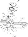
- the two-wheeled vehicle includes a front wheel mounted on the front end of the vehicle body 1 of a two-wheeled vehicle, handlebars 6 provided at the front end of the vehicle body 1 of the two-wheeled vehicle, and a steering bearing sleeve 2 vertically fixed to the front end of the vehicle body 1.
- at least one fixing member may be provided on the outer wall of the steering bearing bushing 2 and fixedly connected to the front end of the vehicle body 1 through the fixing member.
- the mounting screw hole 21 is provided in the outer wall of the steering bearing bushing 2, and the bolt 12 is inserted through the through hole 11 and screwed into the mounting screw hole 21, so that the steering bearing bushing 2 is fixedly mounted on the front end of the vehicle body 1.
- the steering bearing sleeve 2 is provided with a steering bearing fixing rod 4 which is rotatable within the steering bearing sleeve 2.
- the steering bearing fixing rod 4 is fixedly connected to the handlebars and is rotated synchronously with the handlebars.
- a steering bearing (The steering bearing may specifically include a steering bearing 22 and a steering bearing 23 provided at the lead-end and rear-end of the steering bearing fixing rod 4, respectively).
- the steering bearing fixing rod 4 is rotatably mounted in the steering bearing sleeve 2 through the steering bearing (i.e., the steering bearing 22, and the steering bearing 23).
- the steering bearing press ring may be provided and the steering bearing press ring is attached to the end of the steering bearing sleeve to withstand the steering bearing.
- two steering bearing presses 411, 412 are provided.
- the steering bearing press ring 411 and the steering bearing presser 412 are located at both ends of the steering bearing sleeve 2 and are respectively engaged with both ends of the steering bearing sleeve 2.
- the steering bearing presser 411 and the steering bearing presser 412 are engaged with the steering bearing bushings 2, their sides toward the inside of the steering sleeve 2 are against the steering bearing 22 and the diverter bearing 23, respectively.
- a rotatable front wheel is provided on the steering bearing fixing rod 4.
- the front wheel includes a fixed inner hub 3 and an outer wheel rotatable relative to the fixed inner hub 3.
- the fixed internal hub 3 is annular.
- the plane which the fixed internal hub 3 is located coincides with the axis of the steering bearing fixing rod 4. That is, the steering bearing fixing rod 4 is located in an annular region of the fixed internal hub 3 in parallel with the fixed internal hub 3.
- a fixed mounting seat 31 is provided on the fixed internal hub 3.
- the fixed internal hub 3 is fixed to the steering bearing fixing rod 4 through the fixed mounting seat 31. Said handlebars are mounted on said fixed mounting seat 31.
- the outer ring may specifically include an outer hub 5 and a tire 51 provided on the outer hub 5.
- a rotary connecting device or a rotation coupling device is further comprised, and the outer hub 5 is rotatably fitted to the outer ring of the fixed internal hub 3 by the rotation coupling device.
- the rotation coupling device specifically includes a roller frame 52 provided between the outer hub 5 and the fixed internal hub 3.
- a plurality of balls are provided in the ball holder 52, and the balls are in rolling contact with the outer hub 5 and the fixed internal hub 3, respectively.
- the middle portion of the fixed mounting seat 31 is provided with a mounting hole 312, and the fixed internal hub 3 is inserted through the mounting hole 312 via a bolt 311, so as to be fixedly mounted on the screw hole 413 of the steering bearing fixing rod 4.
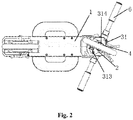
- another mounting seat 314 may be provided on the opposite side of the fixed mounting seat 31 and connected to the other end of the steering bearing fixing rod 4 with the bolt 24 penetrating the mounting seat 314.
- a mounting fixing holes 313 is provided at both ends of the fixed mounting seat 31, respectively.
- the ends of the handlebars 6 have a left branch and a right branch (not shown), and the left and right branches are attached to the mounting fixing holes 313 at both ends of the fixed mounting seat 31 by fixing bolts, respectively.
- a space for rotation of the outer wheel is formed between the left branch and the right branch, whereby the fixed internal hub 3 is fixed and the outer wheel is freely rotatable about the fixed internal hub 3.
Landscapes
- Engineering & Computer Science (AREA)
- Mechanical Engineering (AREA)
- Steering Devices For Bicycles And Motorcycles (AREA)
- Steering Controls (AREA)
- Steering-Linkage Mechanisms And Four-Wheel Steering (AREA)
Claims (4)
- Lenkstruktur, umfassend eine Vorderradnabe, ein Vorderende einer Fahrzeugkarosserie eines tragbaren zweirädrigen Fahrzeugs und eine innere Lenkstruktur, die Lenkstruktur umfassend:ein Vorderrad, das an dem Vorderende der Fahrzeugkarosserie (1) des zweirädrigen Fahrzeugs angebracht ist; undLenkgriffe (6), die am Vorderende der Fahrzeugkarosserie (1) des zweirädrigen Fahrzeugs bereitgestellt sind;wobei die innere Lenkstruktur eine Lenkungslagerhülse (2) aufweist, die vertikal am Vorderende der Fahrzeugkarosserie (1) fixiert ist;wobei die Lenkungslagerhülse (2) mit einer Lenkungslagerfixierungsstange (4) versehen ist, die in der Lenkungslagerhülse (2) drehbar ist; wobei eine Lenkungslagerfixierungsstange (4) fest mit den Lenkgriffen (6) verbunden ist und synchron mit den Lenkgriffen (6) gedreht wird; wobei ein drehbares Vorderrad an der Lenkungslagerfixierungsstange (4) vorgesehen ist;wobei das Vorderrad eine fixierte innere Nabe (3) und ein Außenrad aufweist, das im Verhältnis zu der fixierten Nabe drehbar ist;wobei die fixierte innere Nabe (3) ringförmig ist und die Ebene, in der sich die fixierte innere Nabe (3) befindet, mit der Achse der Lenkungslagerfixierungsstange (4) übereinstimmt; und dadurch gekennzeichnet, dassein fixierter Anbringungssitz an der fixierten inneren Nabe (3) vorgesehen ist und die fixierte innere Nabe (3) durch den fixierten Anbringungssitz fest an der Lenkungslagerfixierungsstange (4) angebracht ist, und die Lenkgriffe (6) an dem fixierten Anbringungssitz angebracht sind;wobei das Außenrad eine äußere Nabe und einen Reifen aufweist, der an der äußeren Nabe angeordnet ist, und ferner aufweisend eine Drehkopplungsvorrichtung;wobei die äußere Nabe (5) durch die Drehkopplungsvorrichtung drehbar auf einen Außenring der fixierten inneren Nabe (3) aufgesetzt ist;wobei die Drehkopplungsvorrichtung umfasst:einen Kugelhalter, der zwischen der äußeren Nabe (5) und der fixierten inneren Nabe (3) bereitgestellt ist, undeine Vielzahl von Kugeln, die in dem Rahmen bereitgestellt ist, wobei die Kugeln jeweils in Rollkontakt mit der äußeren Nabe (5) und der fixierten Nabe stehen;wobei eine Anbringungsöffnung in einem mittleren Abschnitt des fixierten Anbringungssitzes vorgesehen ist und die fixierte innere Nabe (3) durch die Anbringungsöffnung mittels Bolzen perforiert ist, sodass die fixierte Nabe fest an der Lenkungslagerfixierungsstange (4) angebracht ist;wobei der fixierte Anbringungssitz an seinen beiden Enden jeweils mit einem Anbringungsfixierungsloch versehen ist, wobei die Enden der Lenkgriffe (6) eine linke Verzweigung und eine rechte Verzweigung aufweisen und die linke und rechte Verzweigung jeweils durch einen Fixierungsbolzen an einem Anbringungsfixierungsloch an beiden Enden des fixierten Anbringungssitzes angebracht sind; undein Raum zum Drehen des Außenrads zwischen der linken Verzweigung und der rechten Verzweigung gebildet ist.
- Lenkstruktur nach Anspruch 1, wobei die Außenwand der Lenkungslagerhülse (2) mit wenigstens einem Fixierungselement bereitgestellt ist und die Lenkungslagerhülse (2) durch das Fixierungselement fest mit dem Vorderende der Fahrzeugkarosserie (1) verbunden ist.
- Lenkstruktur nach Anspruch 1, wobei die innere Lenkstruktur ferner ein Lenkungslager umfasst und eine Lenkungslagerfixierungsstange (4) durch das Lenkungslager drehbar in der Lenkungslagerhülse (2) angebracht ist.
- Lenkstruktur nach Anspruch 3, wobei die innere Lenkstruktur ferner einen Lenkungslagerring umfasst, der mit dem Ende der Lenkungslagerhülse (2) verbunden ist und am Lenkungslager anliegt.
Applications Claiming Priority (2)
| Application Number | Priority Date | Filing Date | Title |
|---|---|---|---|
| CN201510101084.2A CN104709421B (zh) | 2015-03-06 | 2015-03-06 | 一种便携式两轮车的前轮轮毂内转向结构 |
| PCT/CN2016/071716 WO2016141780A1 (zh) | 2015-03-06 | 2016-01-22 | 一种便携式两轮车的前轮轮毂内转向结构 |
Publications (3)
| Publication Number | Publication Date |
|---|---|
| EP3266691A1 EP3266691A1 (de) | 2018-01-10 |
| EP3266691A4 EP3266691A4 (de) | 2018-12-19 |
| EP3266691B1 true EP3266691B1 (de) | 2020-05-06 |
Family
ID=53409258
Family Applications (1)
| Application Number | Title | Priority Date | Filing Date |
|---|---|---|---|
| EP16761007.0A Not-in-force EP3266691B1 (de) | 2015-03-06 | 2016-01-22 | Innere lenkstruktur einer vorderradnabe eines tragbaren zweiradfahrzeugs |
Country Status (4)
| Country | Link |
|---|---|
| US (1) | US10377437B2 (de) |
| EP (1) | EP3266691B1 (de) |
| CN (1) | CN104709421B (de) |
| WO (1) | WO2016141780A1 (de) |
Families Citing this family (4)
| Publication number | Priority date | Publication date | Assignee | Title |
|---|---|---|---|---|
| CN104709421B (zh) * | 2015-03-06 | 2017-07-18 | 周晓菲 | 一种便携式两轮车的前轮轮毂内转向结构 |
| CN108357603A (zh) * | 2018-03-02 | 2018-08-03 | 骅星科技发展有限公司 | 一种平衡轮及自平衡车 |
| CN110406314B (zh) * | 2019-08-22 | 2024-02-06 | 永康骑客智能科技有限公司 | 一种中空轮体及装有该轮体的车辆 |
| CN111017098B (zh) * | 2019-12-18 | 2021-11-16 | 江西赛骑运动器械制造有限公司 | 一种双向连接关节轴承转向系统 |
Family Cites Families (24)
| Publication number | Priority date | Publication date | Assignee | Title |
|---|---|---|---|---|
| JP2691724B2 (ja) * | 1988-03-18 | 1997-12-17 | 本田技研工業株式会社 | 車両用車輪並びにこの車輪を用いたサスペンション装置及びステアリング装置 |
| EP0393218B1 (de) * | 1989-04-19 | 1994-07-06 | Emco Maier Gesellschaft M.B.H. | Gestell für ein Motorrad |
| DE4126761A1 (de) * | 1991-08-13 | 1993-02-18 | Wilhelm Karl Beirlein Fa | Motorrad mit einer achsschenkellenkung |
| US5201242A (en) * | 1992-04-24 | 1993-04-13 | Chi Yi C | Coupling for supporting a front fork in the head tube of a bicycle |
| JPH07101373A (ja) * | 1993-10-05 | 1995-04-18 | Marui:Kk | 自転車用ハンドルステムの固定構造 |
| US5647684A (en) * | 1995-05-16 | 1997-07-15 | Chen; Chia-Ching | Two-step and toothless bicycle head shaft bowl set |
| US5810380A (en) * | 1996-08-23 | 1998-09-22 | Lin; Wen-Hwa | Bicycle front fork packing structure |
| US5979925A (en) * | 1998-04-02 | 1999-11-09 | Lin; Wen-Hwa | Bicycle head tube packing arrangement |
| WO2002022428A2 (de) * | 2000-09-16 | 2002-03-21 | Michael Prinz | Verbesserte aufhängung von gelenkten laufrädern bei fahrzeugen, insbesondere bei durch gewichtsverlagerung lenkbaren rollern |
| US6322092B1 (en) * | 2000-12-28 | 2001-11-27 | Melton International, Llc | Structure for a steering spindle securing device |
| US6581492B1 (en) * | 2002-01-28 | 2003-06-24 | Far Great Plastics Industrial Co., Ltd. | Handle folding structure for a foldable bicycle |
| CN2567133Y (zh) * | 2002-09-15 | 2003-08-20 | 周游 | 一种新型摩托车前轮轴内转向装置 |
| CN100465055C (zh) * | 2005-12-19 | 2009-03-04 | 佳得车业有限公司 | 自行车的可拆式前叉装置 |
| FR2954266B1 (fr) * | 2009-12-21 | 2011-12-23 | Look Cycle Int | Jeu de direction de cycle a goupille et cycle comportant un tel jeu de direction |
| US7954831B1 (en) * | 2010-03-02 | 2011-06-07 | Ching-Ho Yeh | Scooter having a collapsible structure |
| CN201604774U (zh) * | 2010-03-18 | 2010-10-13 | 叶嘉 | 一种两轮自行车 |
| FR2968266B1 (fr) * | 2010-12-02 | 2012-12-21 | Jacques Benarrouch | Trottinette triptyque pliante a roues escamotables |
| US8613457B2 (en) * | 2011-03-11 | 2013-12-24 | Andreas C. Wegener | Scooter assemblies and scooter deck assemblies |
| US8998224B2 (en) * | 2011-10-05 | 2015-04-07 | Rexco Industrial Ltd. | Scooter |
| EP2604497A1 (de) * | 2011-12-14 | 2013-06-19 | Mondo S.p.A. | Roller |
| CN202764597U (zh) * | 2012-09-18 | 2013-03-06 | 安徽安凯福田曙光车桥有限公司 | 一种安装于整体盘式前桥上的轮毂总成 |
| DE102013207517B4 (de) * | 2013-04-25 | 2016-12-29 | Michael Schäfer | Steuerradaufhängung |
| EP3181436B1 (de) * | 2014-06-20 | 2019-09-18 | Yan, Kexue | Freizeitsportroller |
| CN104709421B (zh) * | 2015-03-06 | 2017-07-18 | 周晓菲 | 一种便携式两轮车的前轮轮毂内转向结构 |
-
2015
- 2015-03-06 CN CN201510101084.2A patent/CN104709421B/zh not_active Expired - Fee Related
-
2016
- 2016-01-22 WO PCT/CN2016/071716 patent/WO2016141780A1/zh not_active Ceased
- 2016-01-22 EP EP16761007.0A patent/EP3266691B1/de not_active Not-in-force
- 2016-01-22 US US15/563,572 patent/US10377437B2/en not_active Expired - Fee Related
Non-Patent Citations (1)
| Title |
|---|
| None * |
Also Published As
| Publication number | Publication date |
|---|---|
| US20180086409A1 (en) | 2018-03-29 |
| EP3266691A1 (de) | 2018-01-10 |
| EP3266691A4 (de) | 2018-12-19 |
| CN104709421A (zh) | 2015-06-17 |
| WO2016141780A1 (zh) | 2016-09-15 |
| CN104709421B (zh) | 2017-07-18 |
| US10377437B2 (en) | 2019-08-13 |
Similar Documents
| Publication | Publication Date | Title |
|---|---|---|
| US9493205B2 (en) | Tricycle with foldable double-wheel assembly | |
| DE102013011496B4 (de) | Muskelkraftbetriebenes mehrrädriges Fahrzeug | |
| US9359037B2 (en) | Front suspension structure for saddle riding type vehicle | |
| US10011316B2 (en) | Vehicle with foldable double-wheel assembly | |
| EP3266691A1 (de) | Innere lenkstruktur einer vorderradnabe eines tragbaren zweiradfahrzeugs | |
| US20160304149A1 (en) | Tricycle with two riding modes | |
| US9988123B2 (en) | Suspension and steering assembly | |
| EP3969356B1 (de) | Lenkmechanismus für ein fahrzeug | |
| US10759486B2 (en) | Three or four wheeled human powered vehicle with dual wheel front steering and single or dual wheel rear drive | |
| EP3042834B1 (de) | Miteinander verbindbare fahrräder | |
| EP2803565B1 (de) | Antriebsgetriebegruppe an einem Lenkrad eines Fahrzeugs | |
| EP2543579B1 (de) | Kopfrohranordnung für ein Fahrrad mit lateraler Öffnung des Kopfrohres zur Aufnahme von Leitungen und Bowdenzügen innerhalb des Rohres | |
| CN201405971Y (zh) | 前轮驱动后轮转向自行车 | |
| EP1982908B1 (de) | Fahrrad mit Neigungslenkung | |
| KR100994394B1 (ko) | 삼륜 자전거 | |
| CN203318590U (zh) | 一种具有电动辅助动力的差速正三轮躺车 | |
| JP2014148206A (ja) | 自動二輪車のフロントフォーク、及び、当該フロントフォークを構成するアウターチューブの筒の外周面に取付けられる外装筒体 | |
| CN201457635U (zh) | 一种脚踏滑板车 | |
| KR101648397B1 (ko) | 역방향 조향 자전거 | |
| CN210126593U (zh) | 一种独轮平衡车辅助装置 | |
| CN107244373B (zh) | 一种两轮车 | |
| CN208198712U (zh) | 一种具有折叠结构的电动车 | |
| AU2025230722A1 (en) | Axle components and vehicles | |
| JP3099720U (ja) | ユニバーサルジョイントを使った、前輪が1輪の自転車及びオートバイの、前輪操舵のための装置 | |
| US387700A (en) | Velocipede |
Legal Events
| Date | Code | Title | Description |
|---|---|---|---|
| STAA | Information on the status of an ep patent application or granted ep patent |
Free format text: STATUS: THE INTERNATIONAL PUBLICATION HAS BEEN MADE |
|
| PUAI | Public reference made under article 153(3) epc to a published international application that has entered the european phase |
Free format text: ORIGINAL CODE: 0009012 |
|
| STAA | Information on the status of an ep patent application or granted ep patent |
Free format text: STATUS: REQUEST FOR EXAMINATION WAS MADE |
|
| 17P | Request for examination filed |
Effective date: 20171005 |
|
| AK | Designated contracting states |
Kind code of ref document: A1 Designated state(s): AL AT BE BG CH CY CZ DE DK EE ES FI FR GB GR HR HU IE IS IT LI LT LU LV MC MK MT NL NO PL PT RO RS SE SI SK SM TR |
|
| AX | Request for extension of the european patent |
Extension state: BA ME |
|
| DAV | Request for validation of the european patent (deleted) | ||
| DAX | Request for extension of the european patent (deleted) | ||
| A4 | Supplementary search report drawn up and despatched |
Effective date: 20181115 |
|
| RIC1 | Information provided on ipc code assigned before grant |
Ipc: B62K 21/00 20060101ALI20181109BHEP Ipc: B62K 21/18 20060101ALI20181109BHEP Ipc: B62K 21/06 20060101AFI20181109BHEP |
|
| RIC1 | Information provided on ipc code assigned before grant |
Ipc: B62K 21/06 20060101AFI20191031BHEP Ipc: B62K 21/18 20060101ALI20191031BHEP Ipc: B62K 21/00 20060101ALI20191031BHEP |
|
| GRAP | Despatch of communication of intention to grant a patent |
Free format text: ORIGINAL CODE: EPIDOSNIGR1 |
|
| STAA | Information on the status of an ep patent application or granted ep patent |
Free format text: STATUS: GRANT OF PATENT IS INTENDED |
|
| INTG | Intention to grant announced |
Effective date: 20200114 |
|
| GRAS | Grant fee paid |
Free format text: ORIGINAL CODE: EPIDOSNIGR3 |
|
| GRAA | (expected) grant |
Free format text: ORIGINAL CODE: 0009210 |
|
| STAA | Information on the status of an ep patent application or granted ep patent |
Free format text: STATUS: THE PATENT HAS BEEN GRANTED |
|
| AK | Designated contracting states |
Kind code of ref document: B1 Designated state(s): AL AT BE BG CH CY CZ DE DK EE ES FI FR GB GR HR HU IE IS IT LI LT LU LV MC MK MT NL NO PL PT RO RS SE SI SK SM TR |
|
| REG | Reference to a national code |
Ref country code: GB Ref legal event code: FG4D |
|
| REG | Reference to a national code |
Ref country code: AT Ref legal event code: REF Ref document number: 1266319 Country of ref document: AT Kind code of ref document: T Effective date: 20200515 Ref country code: CH Ref legal event code: EP |
|
| REG | Reference to a national code |
Ref country code: IE Ref legal event code: FG4D |
|
| REG | Reference to a national code |
Ref country code: DE Ref legal event code: R096 Ref document number: 602016035867 Country of ref document: DE |
|
| REG | Reference to a national code |
Ref country code: LT Ref legal event code: MG4D |
|
| REG | Reference to a national code |
Ref country code: NL Ref legal event code: MP Effective date: 20200506 |
|
| PG25 | Lapsed in a contracting state [announced via postgrant information from national office to epo] |
Ref country code: PT Free format text: LAPSE BECAUSE OF FAILURE TO SUBMIT A TRANSLATION OF THE DESCRIPTION OR TO PAY THE FEE WITHIN THE PRESCRIBED TIME-LIMIT Effective date: 20200907 Ref country code: NO Free format text: LAPSE BECAUSE OF FAILURE TO SUBMIT A TRANSLATION OF THE DESCRIPTION OR TO PAY THE FEE WITHIN THE PRESCRIBED TIME-LIMIT Effective date: 20200806 Ref country code: GR Free format text: LAPSE BECAUSE OF FAILURE TO SUBMIT A TRANSLATION OF THE DESCRIPTION OR TO PAY THE FEE WITHIN THE PRESCRIBED TIME-LIMIT Effective date: 20200807 Ref country code: IS Free format text: LAPSE BECAUSE OF FAILURE TO SUBMIT A TRANSLATION OF THE DESCRIPTION OR TO PAY THE FEE WITHIN THE PRESCRIBED TIME-LIMIT Effective date: 20200906 Ref country code: SE Free format text: LAPSE BECAUSE OF FAILURE TO SUBMIT A TRANSLATION OF THE DESCRIPTION OR TO PAY THE FEE WITHIN THE PRESCRIBED TIME-LIMIT Effective date: 20200506 Ref country code: LT Free format text: LAPSE BECAUSE OF FAILURE TO SUBMIT A TRANSLATION OF THE DESCRIPTION OR TO PAY THE FEE WITHIN THE PRESCRIBED TIME-LIMIT Effective date: 20200506 Ref country code: FI Free format text: LAPSE BECAUSE OF FAILURE TO SUBMIT A TRANSLATION OF THE DESCRIPTION OR TO PAY THE FEE WITHIN THE PRESCRIBED TIME-LIMIT Effective date: 20200506 |
|
| PG25 | Lapsed in a contracting state [announced via postgrant information from national office to epo] |
Ref country code: BG Free format text: LAPSE BECAUSE OF FAILURE TO SUBMIT A TRANSLATION OF THE DESCRIPTION OR TO PAY THE FEE WITHIN THE PRESCRIBED TIME-LIMIT Effective date: 20200806 Ref country code: LV Free format text: LAPSE BECAUSE OF FAILURE TO SUBMIT A TRANSLATION OF THE DESCRIPTION OR TO PAY THE FEE WITHIN THE PRESCRIBED TIME-LIMIT Effective date: 20200506 Ref country code: RS Free format text: LAPSE BECAUSE OF FAILURE TO SUBMIT A TRANSLATION OF THE DESCRIPTION OR TO PAY THE FEE WITHIN THE PRESCRIBED TIME-LIMIT Effective date: 20200506 Ref country code: HR Free format text: LAPSE BECAUSE OF FAILURE TO SUBMIT A TRANSLATION OF THE DESCRIPTION OR TO PAY THE FEE WITHIN THE PRESCRIBED TIME-LIMIT Effective date: 20200506 |
|
| REG | Reference to a national code |
Ref country code: AT Ref legal event code: MK05 Ref document number: 1266319 Country of ref document: AT Kind code of ref document: T Effective date: 20200506 |
|
| PG25 | Lapsed in a contracting state [announced via postgrant information from national office to epo] |
Ref country code: AL Free format text: LAPSE BECAUSE OF FAILURE TO SUBMIT A TRANSLATION OF THE DESCRIPTION OR TO PAY THE FEE WITHIN THE PRESCRIBED TIME-LIMIT Effective date: 20200506 Ref country code: NL Free format text: LAPSE BECAUSE OF FAILURE TO SUBMIT A TRANSLATION OF THE DESCRIPTION OR TO PAY THE FEE WITHIN THE PRESCRIBED TIME-LIMIT Effective date: 20200506 |
|
| PG25 | Lapsed in a contracting state [announced via postgrant information from national office to epo] |
Ref country code: CZ Free format text: LAPSE BECAUSE OF FAILURE TO SUBMIT A TRANSLATION OF THE DESCRIPTION OR TO PAY THE FEE WITHIN THE PRESCRIBED TIME-LIMIT Effective date: 20200506 Ref country code: AT Free format text: LAPSE BECAUSE OF FAILURE TO SUBMIT A TRANSLATION OF THE DESCRIPTION OR TO PAY THE FEE WITHIN THE PRESCRIBED TIME-LIMIT Effective date: 20200506 Ref country code: RO Free format text: LAPSE BECAUSE OF FAILURE TO SUBMIT A TRANSLATION OF THE DESCRIPTION OR TO PAY THE FEE WITHIN THE PRESCRIBED TIME-LIMIT Effective date: 20200506 Ref country code: IT Free format text: LAPSE BECAUSE OF FAILURE TO SUBMIT A TRANSLATION OF THE DESCRIPTION OR TO PAY THE FEE WITHIN THE PRESCRIBED TIME-LIMIT Effective date: 20200506 Ref country code: DK Free format text: LAPSE BECAUSE OF FAILURE TO SUBMIT A TRANSLATION OF THE DESCRIPTION OR TO PAY THE FEE WITHIN THE PRESCRIBED TIME-LIMIT Effective date: 20200506 Ref country code: EE Free format text: LAPSE BECAUSE OF FAILURE TO SUBMIT A TRANSLATION OF THE DESCRIPTION OR TO PAY THE FEE WITHIN THE PRESCRIBED TIME-LIMIT Effective date: 20200506 Ref country code: SM Free format text: LAPSE BECAUSE OF FAILURE TO SUBMIT A TRANSLATION OF THE DESCRIPTION OR TO PAY THE FEE WITHIN THE PRESCRIBED TIME-LIMIT Effective date: 20200506 Ref country code: ES Free format text: LAPSE BECAUSE OF FAILURE TO SUBMIT A TRANSLATION OF THE DESCRIPTION OR TO PAY THE FEE WITHIN THE PRESCRIBED TIME-LIMIT Effective date: 20200506 |
|
| REG | Reference to a national code |
Ref country code: DE Ref legal event code: R097 Ref document number: 602016035867 Country of ref document: DE |
|
| PG25 | Lapsed in a contracting state [announced via postgrant information from national office to epo] |
Ref country code: SK Free format text: LAPSE BECAUSE OF FAILURE TO SUBMIT A TRANSLATION OF THE DESCRIPTION OR TO PAY THE FEE WITHIN THE PRESCRIBED TIME-LIMIT Effective date: 20200506 Ref country code: PL Free format text: LAPSE BECAUSE OF FAILURE TO SUBMIT A TRANSLATION OF THE DESCRIPTION OR TO PAY THE FEE WITHIN THE PRESCRIBED TIME-LIMIT Effective date: 20200506 |
|
| PLBE | No opposition filed within time limit |
Free format text: ORIGINAL CODE: 0009261 |
|
| STAA | Information on the status of an ep patent application or granted ep patent |
Free format text: STATUS: NO OPPOSITION FILED WITHIN TIME LIMIT |
|
| 26N | No opposition filed |
Effective date: 20210209 |
|
| PGFP | Annual fee paid to national office [announced via postgrant information from national office to epo] |
Ref country code: FR Payment date: 20210125 Year of fee payment: 6 |
|
| PG25 | Lapsed in a contracting state [announced via postgrant information from national office to epo] |
Ref country code: SI Free format text: LAPSE BECAUSE OF FAILURE TO SUBMIT A TRANSLATION OF THE DESCRIPTION OR TO PAY THE FEE WITHIN THE PRESCRIBED TIME-LIMIT Effective date: 20200506 |
|
| PGFP | Annual fee paid to national office [announced via postgrant information from national office to epo] |
Ref country code: DE Payment date: 20210128 Year of fee payment: 6 Ref country code: GB Payment date: 20210127 Year of fee payment: 6 |
|
| PG25 | Lapsed in a contracting state [announced via postgrant information from national office to epo] |
Ref country code: MC Free format text: LAPSE BECAUSE OF FAILURE TO SUBMIT A TRANSLATION OF THE DESCRIPTION OR TO PAY THE FEE WITHIN THE PRESCRIBED TIME-LIMIT Effective date: 20200506 |
|
| REG | Reference to a national code |
Ref country code: CH Ref legal event code: PL |
|
| PG25 | Lapsed in a contracting state [announced via postgrant information from national office to epo] |
Ref country code: LU Free format text: LAPSE BECAUSE OF NON-PAYMENT OF DUE FEES Effective date: 20210122 |
|
| REG | Reference to a national code |
Ref country code: BE Ref legal event code: MM Effective date: 20210131 |
|
| PG25 | Lapsed in a contracting state [announced via postgrant information from national office to epo] |
Ref country code: CH Free format text: LAPSE BECAUSE OF NON-PAYMENT OF DUE FEES Effective date: 20210131 Ref country code: LI Free format text: LAPSE BECAUSE OF NON-PAYMENT OF DUE FEES Effective date: 20210131 |
|
| PG25 | Lapsed in a contracting state [announced via postgrant information from national office to epo] |
Ref country code: IE Free format text: LAPSE BECAUSE OF NON-PAYMENT OF DUE FEES Effective date: 20210122 |
|
| PG25 | Lapsed in a contracting state [announced via postgrant information from national office to epo] |
Ref country code: BE Free format text: LAPSE BECAUSE OF NON-PAYMENT OF DUE FEES Effective date: 20210131 |
|
| REG | Reference to a national code |
Ref country code: DE Ref legal event code: R119 Ref document number: 602016035867 Country of ref document: DE |
|
| GBPC | Gb: european patent ceased through non-payment of renewal fee |
Effective date: 20220122 |
|
| PG25 | Lapsed in a contracting state [announced via postgrant information from national office to epo] |
Ref country code: GB Free format text: LAPSE BECAUSE OF NON-PAYMENT OF DUE FEES Effective date: 20220122 Ref country code: DE Free format text: LAPSE BECAUSE OF NON-PAYMENT OF DUE FEES Effective date: 20220802 |
|
| PG25 | Lapsed in a contracting state [announced via postgrant information from national office to epo] |
Ref country code: FR Free format text: LAPSE BECAUSE OF NON-PAYMENT OF DUE FEES Effective date: 20220131 |
|
| PG25 | Lapsed in a contracting state [announced via postgrant information from national office to epo] |
Ref country code: CY Free format text: LAPSE BECAUSE OF FAILURE TO SUBMIT A TRANSLATION OF THE DESCRIPTION OR TO PAY THE FEE WITHIN THE PRESCRIBED TIME-LIMIT Effective date: 20200506 |
|
| PG25 | Lapsed in a contracting state [announced via postgrant information from national office to epo] |
Ref country code: HU Free format text: LAPSE BECAUSE OF FAILURE TO SUBMIT A TRANSLATION OF THE DESCRIPTION OR TO PAY THE FEE WITHIN THE PRESCRIBED TIME-LIMIT; INVALID AB INITIO Effective date: 20160122 |
|
| PG25 | Lapsed in a contracting state [announced via postgrant information from national office to epo] |
Ref country code: MK Free format text: LAPSE BECAUSE OF FAILURE TO SUBMIT A TRANSLATION OF THE DESCRIPTION OR TO PAY THE FEE WITHIN THE PRESCRIBED TIME-LIMIT Effective date: 20200506 |
|
| PG25 | Lapsed in a contracting state [announced via postgrant information from national office to epo] |
Ref country code: MT Free format text: LAPSE BECAUSE OF FAILURE TO SUBMIT A TRANSLATION OF THE DESCRIPTION OR TO PAY THE FEE WITHIN THE PRESCRIBED TIME-LIMIT Effective date: 20200506 |
|
| PG25 | Lapsed in a contracting state [announced via postgrant information from national office to epo] |
Ref country code: TR Free format text: LAPSE BECAUSE OF FAILURE TO SUBMIT A TRANSLATION OF THE DESCRIPTION OR TO PAY THE FEE WITHIN THE PRESCRIBED TIME-LIMIT Effective date: 20200506 |