EP3265402B1 - Code and container of system for preparing a beverage or foodstuff - Google Patents
Code and container of system for preparing a beverage or foodstuff Download PDFInfo
- Publication number
- EP3265402B1 EP3265402B1 EP16707015.0A EP16707015A EP3265402B1 EP 3265402 B1 EP3265402 B1 EP 3265402B1 EP 16707015 A EP16707015 A EP 16707015A EP 3265402 B1 EP3265402 B1 EP 3265402B1
- Authority
- EP
- European Patent Office
- Prior art keywords
- container
- virtual
- preparation
- code
- line
- Prior art date
- Legal status (The legal status is an assumption and is not a legal conclusion. Google has not performed a legal analysis and makes no representation as to the accuracy of the status listed.)
- Active
Links
- 235000013361 beverage Nutrition 0.000 title claims description 69
- 238000002360 preparation method Methods 0.000 claims description 221
- 239000002775 capsule Substances 0.000 claims description 62
- 238000012545 processing Methods 0.000 claims description 51
- 239000000463 material Substances 0.000 claims description 45
- 238000000034 method Methods 0.000 claims description 32
- 230000008569 process Effects 0.000 claims description 11
- 238000004590 computer program Methods 0.000 claims description 10
- 230000002093 peripheral effect Effects 0.000 claims description 3
- 235000013305 food Nutrition 0.000 claims description 2
- 239000012530 fluid Substances 0.000 description 47
- 238000000605 extraction Methods 0.000 description 19
- 238000004891 communication Methods 0.000 description 17
- 238000002156 mixing Methods 0.000 description 14
- 230000008901 benefit Effects 0.000 description 10
- 238000003860 storage Methods 0.000 description 8
- 239000004615 ingredient Substances 0.000 description 7
- 238000002347 injection Methods 0.000 description 6
- 239000007924 injection Substances 0.000 description 6
- 239000000853 adhesive Substances 0.000 description 5
- 230000001070 adhesive effect Effects 0.000 description 5
- 239000000758 substrate Substances 0.000 description 5
- 238000012546 transfer Methods 0.000 description 5
- 235000016213 coffee Nutrition 0.000 description 4
- 235000013353 coffee beverage Nutrition 0.000 description 4
- 238000001816 cooling Methods 0.000 description 4
- 230000000694 effects Effects 0.000 description 4
- 230000006870 function Effects 0.000 description 4
- 230000010354 integration Effects 0.000 description 4
- 239000008267 milk Substances 0.000 description 4
- 235000013336 milk Nutrition 0.000 description 4
- 210000004080 milk Anatomy 0.000 description 4
- XLYOFNOQVPJJNP-UHFFFAOYSA-N water Substances O XLYOFNOQVPJJNP-UHFFFAOYSA-N 0.000 description 4
- 238000006243 chemical reaction Methods 0.000 description 3
- 238000004090 dissolution Methods 0.000 description 3
- 238000004049 embossing Methods 0.000 description 3
- 230000003287 optical effect Effects 0.000 description 3
- 238000000926 separation method Methods 0.000 description 3
- 239000000126 substance Substances 0.000 description 3
- 238000009736 wetting Methods 0.000 description 3
- 244000269722 Thea sinensis Species 0.000 description 2
- 239000004411 aluminium Substances 0.000 description 2
- 229910052782 aluminium Inorganic materials 0.000 description 2
- XAGFODPZIPBFFR-UHFFFAOYSA-N aluminium Chemical compound [Al] XAGFODPZIPBFFR-UHFFFAOYSA-N 0.000 description 2
- 230000015572 biosynthetic process Effects 0.000 description 2
- 238000001514 detection method Methods 0.000 description 2
- 235000015243 ice cream Nutrition 0.000 description 2
- 238000003780 insertion Methods 0.000 description 2
- 230000037431 insertion Effects 0.000 description 2
- 239000004922 lacquer Substances 0.000 description 2
- 230000007246 mechanism Effects 0.000 description 2
- 229910052751 metal Inorganic materials 0.000 description 2
- 239000002184 metal Substances 0.000 description 2
- 239000000203 mixture Substances 0.000 description 2
- 239000004033 plastic Substances 0.000 description 2
- 229920003023 plastic Polymers 0.000 description 2
- 229920000139 polyethylene terephthalate Polymers 0.000 description 2
- 239000005020 polyethylene terephthalate Substances 0.000 description 2
- 235000013618 yogurt Nutrition 0.000 description 2
- 241000931526 Acer campestre Species 0.000 description 1
- 241000195940 Bryophyta Species 0.000 description 1
- 240000006766 Cornus mas Species 0.000 description 1
- 235000003363 Cornus mas Nutrition 0.000 description 1
- 238000013019 agitation Methods 0.000 description 1
- 230000001413 cellular effect Effects 0.000 description 1
- 238000005119 centrifugation Methods 0.000 description 1
- 230000001143 conditioned effect Effects 0.000 description 1
- 235000011950 custard Nutrition 0.000 description 1
- 238000013500 data storage Methods 0.000 description 1
- 230000007423 decrease Effects 0.000 description 1
- 238000011161 development Methods 0.000 description 1
- 238000010586 diagram Methods 0.000 description 1
- 230000035622 drinking Effects 0.000 description 1
- 235000015114 espresso Nutrition 0.000 description 1
- 239000011888 foil Substances 0.000 description 1
- 238000010438 heat treatment Methods 0.000 description 1
- 235000020278 hot chocolate Nutrition 0.000 description 1
- 230000006698 induction Effects 0.000 description 1
- 235000020094 liqueur Nutrition 0.000 description 1
- 239000007788 liquid Substances 0.000 description 1
- 238000012423 maintenance Methods 0.000 description 1
- 238000004519 manufacturing process Methods 0.000 description 1
- 238000012544 monitoring process Methods 0.000 description 1
- 235000011929 mousse Nutrition 0.000 description 1
- 230000035515 penetration Effects 0.000 description 1
- -1 polyethylene terephthalate Polymers 0.000 description 1
- 235000013570 smoothie Nutrition 0.000 description 1
- 235000014347 soups Nutrition 0.000 description 1
- 235000020354 squash Nutrition 0.000 description 1
- 235000013616 tea Nutrition 0.000 description 1
- 230000003313 weakening effect Effects 0.000 description 1
Images


Classifications
-
- B—PERFORMING OPERATIONS; TRANSPORTING
- B65—CONVEYING; PACKING; STORING; HANDLING THIN OR FILAMENTARY MATERIAL
- B65D—CONTAINERS FOR STORAGE OR TRANSPORT OF ARTICLES OR MATERIALS, e.g. BAGS, BARRELS, BOTTLES, BOXES, CANS, CARTONS, CRATES, DRUMS, JARS, TANKS, HOPPERS, FORWARDING CONTAINERS; ACCESSORIES, CLOSURES, OR FITTINGS THEREFOR; PACKAGING ELEMENTS; PACKAGES
- B65D85/00—Containers, packaging elements or packages, specially adapted for particular articles or materials
- B65D85/70—Containers, packaging elements or packages, specially adapted for particular articles or materials for materials not otherwise provided for
- B65D85/804—Disposable containers or packages with contents which are mixed, infused or dissolved in situ, i.e. without having been previously removed from the package
- B65D85/8043—Packages adapted to allow liquid to pass through the contents
- B65D85/8064—Sealing means for the interface with the processing machine
-
- A—HUMAN NECESSITIES
- A47—FURNITURE; DOMESTIC ARTICLES OR APPLIANCES; COFFEE MILLS; SPICE MILLS; SUCTION CLEANERS IN GENERAL
- A47J—KITCHEN EQUIPMENT; COFFEE MILLS; SPICE MILLS; APPARATUS FOR MAKING BEVERAGES
- A47J31/00—Apparatus for making beverages
- A47J31/44—Parts or details or accessories of beverage-making apparatus
- A47J31/4492—Means to read code provided on ingredient pod or cartridge
-
- B—PERFORMING OPERATIONS; TRANSPORTING
- B65—CONVEYING; PACKING; STORING; HANDLING THIN OR FILAMENTARY MATERIAL
- B65D—CONTAINERS FOR STORAGE OR TRANSPORT OF ARTICLES OR MATERIALS, e.g. BAGS, BARRELS, BOTTLES, BOXES, CANS, CARTONS, CRATES, DRUMS, JARS, TANKS, HOPPERS, FORWARDING CONTAINERS; ACCESSORIES, CLOSURES, OR FITTINGS THEREFOR; PACKAGING ELEMENTS; PACKAGES
- B65D77/00—Packages formed by enclosing articles or materials in preformed containers, e.g. boxes, cartons, sacks or bags
- B65D77/22—Details
- B65D77/30—Opening or contents-removing devices added or incorporated during filling or closing of containers
- B65D77/32—Tearing-strings or like flexible elements
- B65D77/36—Tearing-strings or like flexible elements disposed beneath a wrapper, label, or other element of sheet material securing a lid, cover, or container mouth
-
- B—PERFORMING OPERATIONS; TRANSPORTING
- B65—CONVEYING; PACKING; STORING; HANDLING THIN OR FILAMENTARY MATERIAL
- B65D—CONTAINERS FOR STORAGE OR TRANSPORT OF ARTICLES OR MATERIALS, e.g. BAGS, BARRELS, BOTTLES, BOXES, CANS, CARTONS, CRATES, DRUMS, JARS, TANKS, HOPPERS, FORWARDING CONTAINERS; ACCESSORIES, CLOSURES, OR FITTINGS THEREFOR; PACKAGING ELEMENTS; PACKAGES
- B65D85/00—Containers, packaging elements or packages, specially adapted for particular articles or materials
- B65D85/70—Containers, packaging elements or packages, specially adapted for particular articles or materials for materials not otherwise provided for
- B65D85/804—Disposable containers or packages with contents which are mixed, infused or dissolved in situ, i.e. without having been previously removed from the package
- B65D85/8043—Packages adapted to allow liquid to pass through the contents
- B65D85/8058—Coding means for the contents
-
- G—PHYSICS
- G06—COMPUTING; CALCULATING OR COUNTING
- G06K—GRAPHICAL DATA READING; PRESENTATION OF DATA; RECORD CARRIERS; HANDLING RECORD CARRIERS
- G06K19/00—Record carriers for use with machines and with at least a part designed to carry digital markings
- G06K19/06—Record carriers for use with machines and with at least a part designed to carry digital markings characterised by the kind of the digital marking, e.g. shape, nature, code
- G06K19/06009—Record carriers for use with machines and with at least a part designed to carry digital markings characterised by the kind of the digital marking, e.g. shape, nature, code with optically detectable marking
Definitions
- the described embodiments relate generally to beverage or foodstuff preparation systems which prepare a beverage or foodstuff from containers such as coffee capsules, and in particular to codes arranged on the container that encode preparation information for reading by a machine of said system.
- Increasingly preparation machines for the preparation of a beverage or foodstuff are configured to operate using a container that comprises a single-serving of a preparation material, e.g. coffee, tea, ice cream, yoghurt.
- the machine may be configured for preparation by processing said material in the container, e.g. with the addition of fluid, such as milk or water, and the application of mixing thereto, such a machine is disclosed in PCT/EP13/072692 .
- the machine may be configured for preparation by at least partially extracting an ingredient of the material from the container, e.g. by dissolution or brewing.
- Such machines are provided in EP 2393404 A1 , EP 2470053 A1 , EP 2533672 A1 , EP 2509473 A1 , EP 2685874 A1 .
- the increased popularity of these machines may be partly attributed to enhanced user convenience compared to a conventional preparation machine, e.g. compared to a manually operated stove-top espresso maker or cafetiére (French press). It may also be partly attributed to an enhanced preparation process, wherein preparation information specific to the container and/or preparation material therein is: encoded in a code on the container; read by the preparation machine; used by the machine to optimise the preparation process.
- the preparation information may comprise operational parameters of the machine, such as: fluid temperature; preparation duration; mixing conditions.
- EP 2481330 A1 describes a capsule comprising a barcode sequence that is repeatedly printed along a peripheral path of the capsule, wherein the sequence is composed of dots of various sizes and spaced apart from one another such that their projected images while the capsule moves along a linear path form the bars of the barcode.
- WO 2014/206799 discloses a capsule comprising at least two specific bar codes, each bar code carrying a different alternative value of a same beverage preparation setting. A drawback of such codes is that their encoding density is limited, i.e. the amount of preparation information that they can encode is limited. A further drawback is that these codes are highly visible and may be considered aesthetically displeasing.
- EP2525691 discloses a container with a 2D barcode, which has a higher albeit limited encoding density.
- WO 2014/096405 A1 discloses a container with a circular binary code arranged on the bottom, which also has a limited encoding density.
- WO 2011/152296 A1 describes various embodiments of a binary code comprising discrete positions located at intersections between radii and concentric circles. Data is encoded in that a single data unit is placed on each radius at either one of four discrete positions. In a variant embodiment, encoding of data is done by placing one to four data units on each radius. This code also has a limited density of information due to the limited number of discrete positions and data unit combinations.
- US 2007/0189579 A1 and US 8,194914 disclose encoded images comprising a primary image and a secondary image, wherein the angular position of the secondary image relative to the primary image may be used to encode data.
- An object of the present disclosure is to provide a container for beverage or foodstuff preparation material that comprises a code that has a high encoding density. It would be advantageous to provide such a code that is less visible than the prior art. It would be advantageous to provide such a code that is un-complicated such that it does not comprise a large number of symbols. It would be advantageous to provide such a code that is cost-effective to produce and that can be read by a cost-effective code reader. It would be advantageous to provide such a code that can be reliably read and processed.
- a container for use e.g. it is suitably dimensioned by a foodstuff or beverage preparation machine, in particular the machine disclosed in the second embodiment.
- the container for containing beverage or foodstuff preparation material e.g. it has an internal volume and may be food safe.
- the container may be a single-serving container e.g. it is dimensioned for containing a dosage of beverage or foodstuff material for preparation of a single serving (e.g. pre portioned) of said product.
- the container may be a single-use container, e.g.
- the container comprises (e.g. on a surface thereof) a code encoding preparation information, the code comprising a reference portion and a data portion: the reference portion providing a reference position for the data portion.
- the reference portion comprising an arrangement, which may by linear, of at least two reference units defining a reference line r ; the data portion comprising at least one data unit, wherein the data unit is arranged on (e.g.
- the data unit occupies a distance d along said encoding line D, as a variable to encode a parameter of the preparation information, whereby said encoding line D is semi (i.e. it comprises a segment of a circle) or fully circular and is arranged with a tangent thereto orthogonal the reference line r at said intersection point.
- a Polar coordinate system can be utilised, whereby: the origin is typically a reference unit of an reference line orientation identifier; each data unit has a radial distance from the origin (which is equivalent to the radial distance of the associated reference position); each data unit has an angle defined as between the reference line r and its radial line. The distance d can then be conveniently determined by the said angle and said radial distance.
- Image processing using this coordinate system is more convenient than for a Cartesian coordinate system, whereby the axis are defined by a reference line and a linear encoding line that extends orthogonally thereto, since with the Cartesian arrangement the image of the code requires reorientation such that the Cartesian axes of the code are aligned with those of the image processor. In this way a more cost-effective image processor can be used.
- the code has a high encoding density since a plurality (such as 2, 3, 4, 5, 6, 7 or 8) of encoding lines D, each with a data unit, can be arranged concentrically about the origin, with each comprising one or more associated data unit.
- a data unit may be arranged on the encoding line any continuous distance d from the intersection point.
- the code has a high encoding density as it can encode information in a continuous manner rather than a discrete manner.
- the data units may be arranged only discrete distances from the intersection point (i.e. the data unit can only occupy one of a plurality of predetermined positions along the line D, which generally do not overlap and may have a discrete separation between adjacent positions).
- the data units may be arranged with combinations of continuous and discrete distances.
- the preparation information may comprise information that is related to a preparation process, e.g. one or more parameters used by the machine such as: temperature; torque and angular velocity (for mixing units of machines which effect mixing); flow rate/volume; pressure; % cooling power; time (e.g. for which a phase comprising one or more of the aforesaid parameters are applied for); expiry date; container geometric properties; phase identifier (for containers comprising multiple codes, whereby each of which encodes a distinct phase of a preparation operation); container identifier; a recipe identifier that may be used to retrieve one or more parameters of the machine which are used by the machine to prepare the product, wherein said parameters may be stored on the machine; pre-wetting volume.
- parameters used by the machine such as: temperature; torque and angular velocity (for mixing units of machines which effect mixing); flow rate/volume; pressure; % cooling power; time (e.g. for which a phase comprising one or more of the aforesaid parameters are applied for); expiry date; container geometric
- the code preferably has a peripheral length (e.g. a diameter or side length of a rectangle) of 600 - 1600 ⁇ m or 600 - 6000 ⁇ m. Accordingly an object of the disclosure is achieved since the code is not particularly visible. More particularly, the units (i.e. the data units and reference units) that comprise the code preferably have a unit length of 50 - 250 ⁇ m.
- the aforesaid unit length may be defined as: a diameter for a substantially circular unit; a side length for a quadrilateral unit; other suitable measure of length for a unit of another shape.
- the encoding area is preferably circular at a periphery, whereby the encoding lines D extend concentrically about a centre thereof.
- the reference portion may comprise a reference unit as a reference line orientation identifier.
- the reference unit of said orientation identifier may be identifiable from other units of code by one or more means, e.g.: it is without an associated encoding line D that has a data unit arranged thereon and that intersects said reference unit; it comprises a reference unit distinct from the other units of the code in terms of one of more of the following: shape, size, colour; it is arranged at an end of said reference line r.
- One advantage is that it is convenient for an image processor to determine an orientation of the reference line r.
- the reference unit defining of the orientation identifier is preferably arranged at a centre of a circle defined by the circularly extending encoding line D.
- the data portion may comprise a plurality of encoding lines D (e.g. up to 2, 3, 4, 5, 6, 10, 16, 20 or more), each comprising a corresponding arrangement of a data unit (i.e. the data unit is arranged a distance d from an intersection point to at least partially encode a parameter).
- the encoding lines D are concentrically arranged and preferably intersect the reference line r at a different position.
- a further reference unit of the reference portion may be identifiable by one or more of the following: it may be arranged at a greater radial position from said orientation identifier than the data units and/or at a predetermined reserved radial position from said orientation identifier (e.g. a particular position, e.g. 400 - 600 ⁇ m), whereby the data units are not arranged at said predetermined radial position; it is distinct from the other units of the code in terms of one of more of the following: shape, size, colour.
- a predetermined reserved radial position from said orientation identifier e.g. a particular position, e.g. 400 - 600 ⁇ m
- the data portion may have an encoding area, within which the encoding lines D are arranged, the data units thereof being arrange within the bounds of the encoding area.
- the encoding line D may intersect the reference line r at a reference position and the reference position may be absent a reference unit, whereby the or each reference position is arranged a predetermined distance along the reference line, e.g. from the reference unit of the orientation identifier or other position, e.g. the reference units are not arranged within the encoding area.
- One advantage is that the encoding density is increased since the data units can be arranged in close proximity to the reference line r, e.g. without needing to ensure there is adequate separation between the data unit and a reference unit that would otherwise be on said line.
- the aforesaid predetermined distance can be defined as a set amount such that the reference positions are equidistant e.g. a distance between the ends of the reference line r divided by a number of reference positions or divided by the number of reference positions plus a particular amount such as 1 or 2.
- a portion of the encoding area may be bounded by the reference line r, e.g. the encoding area is annular and is radially intersected by the reference line.
- the data units are not arranged in close proximity to the centre of the annuli where the circumferential distance of the encoding line D is less such that there is less precision in the determined distance d.
- the encoding line D may intersect the reference line r at a reference position, whereby the reference position comprises a reference unit.
- the image processor can determine conveniently the positions of the encoding lines D. A portion of the encoding area may be proximal the reference line r.
- the data unit may further encode metadata associated with the parameter.
- the metadata is preferably encoded discretely (e.g. it can assume one of a predetermined number of values).
- the metadata is generally to: enable identification of the particular parameter; and/or a property associated with the parameter (e.g. a ⁇ of an exponent).
- a unit length of a data unit may be selected from one of a plurality of predetermined unit lengths as a variable to encode the metadata.
- the aforesaid unit length may be defined as: a diameter for a substantially circular unit; a side length for a quadrilateral unit; other suitable measure of length for a unit of another shape.
- An offset of a centre of a data unit from the encoding line along a linear line, the line at a point of intersection with the encoding line D is orthogonal thereto, may be selected from one of a plurality of predetermined offsets as a variable to encode the metadata.
- An offset of a centre of a data unit from the encoding line D along a line, the line extending radially from a centre of the circular encoding line D, is selected from one of a plurality of predetermined offsets as a variable to encode the metadata.
- Preferably said offset is achieved within the bounds of at least part of the associated data unit intersecting the encoding line D.
- a plurality of data units may be arranged along a single encoding line D.
- One advantage is that the encoding density is increased.
- Each of the said data units may encode a separate parameter.
- a plurality of the data units may encode a single parameter, whereby a distance d encoding said parameter may be a function (e.g. an average or a multiple) of the distances dn of said plurality of data units.
- each data unit may be identifiable by the metadata.
- the data units and reference units may be formed by one of the following: printing (e.g. by a conventional ink printer: one advantage is that the code can be conveniently and cost-effectively formed); engraving; embossing.
- the code may be formed directly on a surface of the container, e.g. the substrate for the units is integral with the container. Alternatively the code may be formed on an attachment, which is attached to the container.
- the container may comprise the beverage or foodstuff preparation material contained therein.
- the container may comprise one of the following: a capsule; packet; a receptacle for consumption of the beverage or foodstuff therefrom.
- the capsule may have an internal volume of 5 - 80 ml.
- the receptacle may have an internal volume of 150 - 350 ml.
- the packet may have an internal volume of 150 - 350 ml or 200 - 300 ml or 50 - 150 depending on the application.
- a beverage or foodstuff preparation system comprising a container according to the first embodiment and a beverage or foodstuff preparation machine, said preparation machine comprising: a preparation unit to receive a container and to prepare a said beverage or foodstuff therefrom; a code processing system operable to: obtain a digital image of the code of the container; process said digital image to decode the encoded preparation information; a control system operable to effect one more of the following: control of said preparation unit using said decoded preparation information; use the operation information to monitor container consumption for re-ordering, e.g. via a server system through a communication interface; use preparation information to determine if a container has exceeded its expiry date.
- the preparation unit is generally operable perform said preparation by the addition of fluid, such as water or milk to the beverage or foodstuff material.
- the container processing subsystem may comprise one of an: an extraction unit; a dissolution unit; a mixing unit.
- the container processing subsystem may further comprise a fluid supply that is operable to supply fluid to the aforesaid unit.
- the fluid supply comprises a fluid pump and a fluid heater.
- the aforesaid units may be configured for operation with a container containing beverage or foodstuff material.
- Processing of the digital image to decode the preparation information may comprise: locating the units of the code; identifying the reference units and determining therefrom a reference line r ; determining for each data unit a distance d along the encoding line D from the reference line r.
- the locating of the units of the code may comprise one or more of the following: conversion of the digital image to a binary image; determining a centre of the units by feature extraction; determining a size/area/shape of the units by pixel integration (i.e. determining a number of pixels of a shaded region that comprise the unit.
- Identifying the reference units and determining therefrom a reference line r may comprise one or more of the following: identifying units with a linear arrangement; identifying units that are a predetermined distance apart; identifying units that are a particular shape or size, e.g. the reference unit of an orientation identifier; identifying a reference unit corresponding to the orientation identifier that is arranged at a centre of a circle defined by the circular extending encoding lines D and determining a reference unit with a greater radial position from the orientation identifier than the data units and/or at a predetermined reserved radial position from the orientation identifier.
- Determining for each data unit a distance d along the encoding line D from the reference line r may comprise determining a circumferential distance, i.e. by means of the angle observed at the centre of the encoding line between the reference line r and the data unit together with the radial distance of said data unit from said centre.
- it may comprise determining an angular distance, i.e. by means of the angle observed at the centre of the encoding line between the reference line r and the data unit, whereby the radial distance may be used to identify the data unit with respect to a reference position. The latter is preferably since less processing steps are required. Determining said distance may include correcting for magnification/reading distance.
- Processing of the digital image to decode the preparation information may further comprise converting a distance d into an actual value of a parameter V p , using a stored relationship (i.e. stored on a memory unit of the machine) between the parameter and distance d.
- the relationship may be linear, e.g. V p ⁇ d and/or it may be non-linear.
- the relationship may comprise at least one selected from a group consisting of: a logarithmic relationship, e.g. V p ⁇ log(d); an exponential relationship, e.g. V p ⁇ e d ; a polynomial; a step function; linear.
- Exponential and logarithmic relationships are particular advantageous when the accuracy of a parameter is important at low values and less important at high values or the converse respectively.
- the relationship is stored as an equation or as a lookup table.
- the relationship may be applied to any suitable variable of the preparation information, such as: temperature; torque; flow rate/volume; pressure; % cooling power.
- One advantage is the execution of complex recipes, which may be determined by the particular material in the container and the functionality of the machine.
- Processing of the digital image to decode the preparation information may further comprise determining metadata associated with the data unit of the encoded parameter, e.g. by one or more of the following: determining a unit length by feature extraction or overall area/shape by pixel integration; determining an offset of a data unit to the encoding line D by feature extraction.
- a third embodiment is a method of preparing a beverage or foodstuff, using the system according to the second embodiment, the method comprising: obtaining a digital image of the a code of a container according to the first embodiment; processing said digital image to decode the encoded preparation information; operating a control system to effect one more of the following: control of said preparation unit using said decoded preparation information; use the operation information to monitor container consumption for re-ordering, e.g. via a server system through a communication interface; use preparation information to determine if a container has exceeded its expiry date.
- the method may further comprise any of the steps for processing of the digital image as defined by the third embodiment.
- an attachment configured for attachment to a container of a beverage or foodstuff preparation machine according to the first embodiment.
- the attachment may comprise: a carrier carrying on a surface thereof a code as described in the first embodiment; an attachment member for attachment to said container.
- the attachment member is preferably configured for attaching said carrier to the container as if it were formed integrally on the container. In this way it can be read by the image capturing device as if it formed integrally thereto.
- suitable attachment members comprise: an adhesive strip; a mechanical fastener such as a clip or bolt.
- the attachment configured for attachment to a beverage or foodstuff preparation machine according to the second embodiment.
- the attachment may comprise: a carrier carrying on a surface thereof a code as described in the first embodiment; an attachment member for attachment to said machine.
- the attachment member is preferably configured for attaching said carrier to the machine at a position between an image capturing device of said machine and the container when received, such that the code thereon is proximate said container. In this way it can be read by the image capturing device as if it were attached to the container.
- suitable attachment members comprise: extensions attached to said carrier comprising an adhesive strip or a mechanical fastener such as a clip, bolt or bracket.
- Disclosed herein according to a sixth embodiment is a use of a container as defined in the first embodiment or the attachments as defined in the fourth and fifth embodiment for a beverage or foodstuff preparation machine as defined in the second embodiment.
- a seventh embodiment is a computer program for a processor of a code processing system of a beverage or foodstuff preparation machine as defined the second embodiment, the computer program comprising program code to: obtain (e.g. by controlling an image capturing device) a digital image of a code of a container according to the first embodiment; process said digital image to decode the encoded preparation information.
- the computer program may further comprise program code for effecting any of the steps of processing of the digital image as defined by the second embodiment.
- the functional units described by the computer programs generally herein may be implemented, in various manners, using digital electronic logic, for example, one or more ASICs or FPGAs; one or more units of firmware configured with stored code; one or more computer programs or other software elements such as modules or algorithms; or any combination thereof.
- One embodiment may comprise a special-purpose computer specially configured to perform the functions described herein and in which all of the functional units comprise digital electronic logic, one or more units of firmware configured with stored code, or one or more computer programs or other software elements stored in storage media.
- Non-transitory computer readable medium comprising the computer program according to seventh embodiment.
- the non-transitory computer readable medium may comprise a memory unit of the processor or other computer-readable storage media for having computer readable program code stored thereon for programming a computer, e.g. a hard disk, a CD-ROM, an optical storage device, a magnetic storage device, Flash memory.
- a ninth embodiment is provided a use of a code as defined in the first embodiment for encoding preparation information, preferably on: a container of a beverage or foodstuff preparation machine, the container for containing beverage or foodstuff material as defined in the first embodiment; or an attachment according to the seventh or eighth embodiment.
- Disclosed herein according to an tenth embodiment is a method of encoding preparation information, the method comprising forming a code on: a container for a beverage or foodstuff preparation machine, the container for containing beverage or foodstuff material; or an attachment for attachment to said container or said machine.
- the method may comprise encoding information with the code according to any feature of the first embodiment.
- the method may comprise: arranging at least two reference units to define a reference line r of a reference portion; and least partially encoding a parameter of the preparation information with a data portion of the code by arranging a data unit on an encoding line D that intersects the reference line r, the data unit being arranged a distance d extending along the encoding line D from said intersection as a variable for said encoding, whereby said encoding line D is circular and is arranged with a tangent thereto orthogonal the reference line r at said intersection point.
- the method may comprise forming the code by one of the following: printing; engraving; embossing.
- Disclosed herein according to an eleventh embodiment is an information carrying medium comprising the code according to the first embodiment.
- the information carrying medium may comprise the container as defined herein, either of the attachments as defined herein, or a substrate, such as an adhesive strip of other suitable medium.
- the method of encoding preparation information according to the second embodiment may be applied to the information carrying medium.
- the method of decoding preparation information according to the third aspect may be applied to the information carrying medium.
- the beverage or foodstuff preparation machine according to the fourth embodiment may be configured for operation with the information carrying medium, e.g. via its attachment to the container or other suitable component, such as either of the aforedescribed attachments.
- the system according to fifth may comprise the information carrying medium.
- the method of preparing a beverage or foodstuff of the sixth embodiment may be adapted to comprise obtaining a digital image of the code of the information carrying medium.
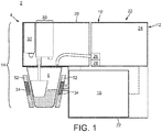
- a beverage or foodstuff preparation system 2 comprises: a beverage or foodstuff preparation machine 4; a container 6, which are described sequentially.
- the beverage or foodstuff preparation machine 4 is operable to process a portion of beverage or foodstuff material, hereon preparation material, to a foodstuff and/or beverage for consumption by eating and/or drinking.
- a foodstuff material as defined herein typically comprises a substance capable of being processed to a nutriment generally for eating, which may be chilled or hot, non-exhaustive examples of which are: yoghurt; mousse; parfait; soup; ice cream; sorbet; custard; smoothies.
- the foodstuff is a liquid, gel or paste foodstuff.
- a beverage material as defined herein may comprise a substance capable of being processed to a potable substance, which may be chilled or hot, non-exhaustive examples of which are: tea; coffee, including ground coffee; hot chocolate; milk; cordial. It will be appreciated that there is a degree of overlap between both definitions, i.e. a said machine 4 can prepare both a foodstuff and a beverage.
- the preparation machine 4 is generally dimensioned for use on a work top, e.g. it is less than 70 cm in length, width and height.
- the preparation machine 4 may have various configurations depending on the particular type of beverage and/or foodstuff it is intended for preparation of, examples of which are:
- preparation machine 4 can be considered to comprise: a housing 10; a preparation unit 14; a control system 16; code processing system 18, which are described sequentially:
- the housing 10 houses and supports the mentioned components and comprises: a base 20 for abutment of a horizontally arranged support surface; a body 22 for mounting thereto the components.
- the preparation unit 14 may be operable to at least partially prepare a foodstuff/beverage from preparation material arranged in: a single-serving, single use container 6; a container 6 that is a receptacle for end-user consumption therefrom; a combination thereof. Embodiments of each configuration of which will be discussed.
- the preparation unit 14 comprises a fluid supply 12 that is operable to supply fluid used during preparation, which is in general water or milk that maybe conditioned (i.e. heated or cooled), typically to the container 6 (or receptacle depending on the embodiment of the machine 4).
- the fluid supply 12 typically comprises: a reservoir 24 for containing fluid, which in most applications is 1 - 5 litres of fluid; a fluid pump 26, such as a reciprocating or rotary pump that may be driven by an electrical motor or an induction coil; a an optional fluid heater 28, which generally comprises an in-line, thermo block type heater; an outlet for supplying the fluid to the preparation unit 14.
- the reservoir 24, fluid pump 26, fluid heater 28, and outlet are in fluid communication with each other in any suitable order.
- the fluid supply 12 may comprise a connection to an external fluid source e.g. a water main.
- the preparation unit 14 is operable to prepare preparation material stored in a container 6 that is a receptacle, such as a cup, pot or other suitable receptacle configured to hold approximately 150 - 350 ml of prepared product.
- a receptacle such as a cup, pot or other suitable receptacle configured to hold approximately 150 - 350 ml of prepared product.
- the preparation unit 14 may be referred to as a mixing unit and may comprise an: agitator unit 30; auxiliary product unit 32; thermal exchanger 34; receptacle support 52, which will be described sequentially.
- the agitator unit 30 is operable to agitate preparation material within the receptacle 6 for at least partial preparation thereof.
- the agitator unit 30 may comprise any suitable mixing arrangement, e.g. a: planetary mixer; spiral mixer; vertical cut mixer.
- the agitator unit 30 comprises: an implement for mixing having a mixing head for contact with the preparation material; and a drive unit, such as an electric motor or solenoid, to drive the mixing implement.
- the mixing head comprises an agitator that rotates with a radial angular velocity W1 on an offset shaft that rotates with gyration angular velocity W2, such an arrangement is disclosed in PCT/EP13/072692 .
- the auxiliary product unit 32 is operable to supply an auxiliary product, such as a topping, to the container 6.
- the auxiliary product unit 32 comprises: a reservoir to store said product; an electrically operated dispensing system to effect the dispensing of said product from the reservoir.
- the thermal exchanger 34 is operable to transfer and/or extract thermal energy from the container 6.
- transfer of thermal energy it may comprise a heater such as thermo block.
- extraction of thermal energy it may comprise heat pump such as a refrigeration-type cycle heat pump.
- the receptacle support 52 is operable to support the container 6 during a preparation process such that the container 6 remains stationary during agitation of the preparation material therein by the agitator unit 30.
- the receptacle support 52 preferably is thermally associated with the thermal exchanger 34 such that transfer of thermal energy can occur with a supported receptacle.
- the afore-described first embodiment preparation unit 14 further comprises a dispensing mechanism for receiving a container 6 and dispensing the associated preparation material into the receptacle, where it is prepared.
- a dispensing mechanism for receiving a container 6 and dispensing the associated preparation material into the receptacle, where it is prepared.
- a collapsible portion of the container comprises a geometric configuration and/or portion of weakening such that said portion collapses in preference to a retaining portion upon the application of axial load through both portions.
- the container processing unit 14 comprises a mechanical actuation device configured to apply an axial load to collapse said container, an example of which is provided in the reference application.
- the preparation unit 14 may be referred to as an extraction unit and may be operable: to receive the container 6 containing preparation material; process the container 6 to extract one or more ingredients of a beverage therefrom, and to dispense the said ingredients into an alternate receptacle for end-user consumption.
- the container is generally a single-use, single-serving container such as a capsule or packet: a preparation unit 14 for use with the said capsule will initially be described followed by a variant machine for use with said packet.
- the preparation unit 14 is operable to move between a capsule receiving position and a capsule extraction position, when moving from the capsule extraction position to the capsule receiving position, the extraction unit may be moved through or to a capsule ejection position, wherein a spent capsule can be ejected therefrom.
- the preparation unit typically comprises: an injection head; a capsule holder; a capsule holder loading system; a capsule insertion channel; a capsule ejection channel, which are described sequentially.
- the injection head is configured to inject fluid into a cavity of the capsule when held by the capsule holder, and to this end has mounted thereto an injector, which has a nozzle that is in fluid communication with the outlet of the fluid supply.
- the capsule holder is configured to hold the capsule during extraction and to this end it is operatively linked to the injection head.
- the capsule holder is operable to move to implement the said capsule receiving position and capsule extraction position: with the capsule holder in the capsule receiving position a capsule can be supplied to the capsule holder from the capsule insertion channel; with the capsule holder in the capsule extraction position a supplied capsule is held by the holder, the injection head can inject fluid into the cavity of the held capsule, and one or more ingredients can be extracted therefrom.
- the capsule holder can be moved through or to the said capsule ejection position, wherein a spent capsule can be ejected from the capsule holder via the capsule ejection channel.
- the capsule holder loading system is operable to drive the capsule holder between the capsule receiving position and the capsule extraction position.
- the preparation unit 14 can operate by means of injection of fluid at pressure into the cavity of the capsule 6, e.g. at up to 20 bar, which can be achieved by means of the injection head and pump 26. It may alternatively operate by centrifugation as disclosed in EP 2594171 A1 , which is incorporated herein by reference. Further examples of suitable preparation units are provided in EP 2393404 A1 , EP 2470053 A1 , EP 2533672 A1 , EP 2509473 A1 EP 2685874 A1 and EP 2594171 A1 .
- the preparation unit 14 may alternatively comprise a dissolution unit configured as disclosed in EP 1472156 and in EP 1784344 , which are incorporated herein by reference.
- the preparation unit 14 is operable to receive the packet and to inject, at an inlet thereof, fluid from the fluid supply 12.
- the injected fluid mixes with preparation material within the packet to at least partially prepare the beverage, which exits the packet via an outlet thereof.
- the preparation unit 14 comprises: a support mechanism to receive an unused packet and eject a spent packet; an injector configured to supply fluid to the packet from the outlet of the fluid supply. Further detail is provided in WO 2014/125123 , which is incorporated herein by reference.
- the control system 16 is operable to control the preparation unit 14 to prepare the beverage/foodstuff.
- the control system 16 typically comprises: a user interface 36; a processor 38; optional sensors 40; a power supply 42; an optional communication interface 44, which are described sequentially.
- the user interface 36 comprises hardware to enable a user to interface with the processor 38 and hence is operatively connected thereto. More particularly: the user interface receives commands from a user; the user interface signal transfers the said commands to the processor 38 as an input.
- the commands may, for example, be an instruction to execute a preparation process and/or to adjust an operational parameter of the preparation machine 4 and/or to power on or off the beverage preparation machine 4.
- the processor 38 may also output feedback to the user interface 36 as part of the preparation process, e.g. to indicate the beverage preparation process has been initiated or that a parameter associated with the process has been selected.
- the hardware of the user interface 36 may comprise any suitable device(s), for example, the hardware comprises one or more of the following: buttons, such as a joystick button or press button; joystick; LEDs; graphic or character LDCs; graphical screen with touch sensing and/or screen edge buttons.
- the sensors 40 are operatively connected to the processor 38 to provide an input for monitoring of the preparation process and/or a status of the preparation machine 4.
- the input can be an analogue or digital signal.
- the sensors 40 typically comprise one or more of the following: fluid level sensors associated with the reservoir 24; flow rate sensors associated with the fluid pump 26; temperature sensors associated with the thermal exchanger 28.
- the sensors may further comprise: fluid level sensors operable to measure a fluid level in the receptacle; sensors for measuring a temperature of a product in the receptacle; sensors for measuring the toque applied by the mixing head of the agitator unit 30 to the product; sensors for measuring the velocity of the mixing head of the agitator unit 30; receptacle detection sensors to detect the presence of the receptacle supported by the receptacle support 52.
- the sensors may further comprise: position sensors associated with the preparation unit 14 that are operable to sense the position thereof; container 6 (i.e. capsule or packet) detection sensors to detect the presence of the container supplied by a user.
- the processor 38 is operable to: receive an input, e.g. the commands from the user interface 36 and/or from the sensors 40; process the input according to program code stored on a memory unit (or programmed logic); provide an output, which is generally a preparation process.
- the output may comprise: operating the code processing system 18 to determine preparation information on the container 6; operating the preparation unit 14 in accordance with the determined information. Operation of the preparation unit 14 can be open-loop control, or more preferable closed-loop control using the input signal from the sensors 40 as feedback.
- the processor 38 generally comprises memory, input and output system components, which are arranged as an integrated circuit, typically as a microprocessor or a microcontroller.
- the processor 38 may comprise other suitable integrated circuits, such as: an ASIC; a programmable logic device such as an FPGA; an analogue integrated circuit, such as a controller.
- the aforementioned program code can be considered programed logic or to additionally comprise programmed logic.
- the processor 38 may also comprise one or more of the aforementioned integrated circuits, i.e. multiple processors.
- the processor 38 generally comprises a memory unit 46 for storage of the program code and optionally data.
- the memory unit typically comprises: a non-volatile memory e.g. EPROM, EEPROM or Flash for program code and operating parameter storage; volatile memory (RAM) for data storage.
- the memory unit may comprise separate and/or integrated (e.g. on a die of the processor) memory.
- the program code stored on a memory unit can be idealised as comprising a preparation program 48 that is executable by the processor 38 to execute said preparation process.
- the preparation process comprises: determining the preparation information from the container (i.e. by interfacing with the code processing system 18); using to control said comprising the information and/or other information that may be stored as data on the memory unit 46 and/or input via the user interface 36.
- the determined information may as an alternative or in addition be used by the preparation program 48 or a device in communication therewith (e.g. a server communicating with the preparation machine over a network such as the internet via a communication interface): to monitor container 6 consumption for re-ordering; to scheduled maintenance of the preparation machine; to monitor machine usage.
- the power supply 42 is operable to supply electrical energy to the processor 38 and associated level.
- the power supply 42 may comprise various means, such as a battery or a unit to receive and condition a mains electrical supply.
- the power supply 42 may be operatively linked to part of the user interface 36 for powering on or off the preparation machine 4.
- the communication interface 44 is for data communication of the beverage preparation machine 4 with another device/system, typically a server system.
- the communication interface 44 can be used to supply and/or receive information related to the preparation process, such as container consumption information and/or preparation process information.
- the communication interface 44 can be configured for cabled media or wireless media or a combination thereof, e.g.: a wired connection, such as RS-232, USB,
- the communication interface 44 is operatively connected to the processor 38.
- the communication interface comprises a separate processing unit (examples of which are provided above) to control communication hardware (e.g. an antenna) to interface with the maser processor 38.
- control communication hardware e.g. an antenna
- less complex configurations can be used e.g. a simple wired connection for serial communication directly with the processor 38.
- the code processing system 18 is operable: to obtain an image of a code on the container 6; to process said image to decode the encoded preparation information.
- the code processing system 18 comprises an: image capturing device 54; image processing device 56; output device 72, which are described sequentially.
- the image capturing device 54 is operable to capture a digital image of the code and to transfer, as digital data, said image to the image processing device 56.
- the image capturing device 54 is arranged a predetermined distance away from the code when obtaining the digital image; in an example wherein the image capturing device 54 comprises a lens the magnification of the lens is preferably stored on a memory of the image processing device 56.
- the image capturing device 54 comprises any suitable optical device for capturing a digital image consisting of the latter discussed micro-unit code composition; examples of suitable optical devices are: Sonix SN9S102; Snap Sensor S2 imager; an oversampled binary image sensor.
- the image processing device 56 is operatively connected to the image capturing device 54 and is operable to process said digital data to decode preparation information encoded therein. Processing of the digital data is discussed in the following paragraphs.
- the image processing device 56 may comprise a processor such as a microcontroller or an ASIC. It may alternatively comprise the aforesaid processor 38, in such an embodiment it will be appreciated that the output device is integrated in the processor 38.
- the image processing device 56 typically comprises a code processing program.
- An example of a suitable image processing device is the Texas Instruments TMS320C5517.
- the output device 72 is operatively connected to the image processing device 56 and is operable to output digital data that comprises the decoded preparation information to the processor 38, e.g. by means of a serial interface.
- the container 6 may comprise, depending on the embodiment of the preparation machine 4 a: receptacle comprising preparation material for preparation and end-user consumption therefrom; a capsule or packet comprising preparation material for preparation therefrom.
- the container 6 may be formed from various materials, such as metal or plastic or a combination thereof. In general the material is selected such that it is: food-safe; it can withstand the pressure/temperature of the preparation process. Suitable examples of containers are provided following.
- the container 6 when not in packet form generally comprises: a body portion 58 defining a cavity for the storage of a dosage of a preparation material; a lid portion 60 for closing the cavity; a flange portion 62 or other suitable portion for connection of the body portion and flange portion, the flange portion generally being arranged distal a base of the cavity.
- the body portion may comprise various shapes, such as a disk, frusto-conical or rectangular cross-sectioned. Accordingly, it will be appreciated that the capsule 6 may take various forms, an example of which are provided in figure 3A , which may generically extend to a receptacle/capsule as defined herein.
- the container 6 may be distinguished as a receptacle for end-user consumption therefrom when configured with an internal volume of 150 - 350 ml. In a similar fashion a capsule may by distinguished when configured with an internal volume of less than 100 ml.
- the container 6 in collapsible configuration may comprise an internal volume of 5 ml - 250 ml.
- the container 6 when in packet form as shown in figure 3B generally comprises: an arrangement of sheet material 64 (such as one or more sheets joined at their periphery) defining an internal volume 66 for the storage of a dosage of a preparation material; an inlet 68 for inflow of fluid into the internal volume 66; an outlet 70 for outflow of fluid and beverage/foodstuff material from the internal volume.
- the inlet 68 and outlet 70 are arranged on a body of an attachment (not shown), which is attached to the sheet material.
- the sheet material may be formed from various materials, such as metal foil or plastic or a combination thereof.
- the volume 66 may be 150 - 350 ml or 200 - 300 ml or 50 - 150 depending on the application.
- a code 74 of the container 6 encodes preparation information, which generally comprises information related to the associated preparation process.
- said information may encode one or more parameters, which may comprise one of more of a: fluid pressure; fluid temperature (at container inlet and/or outlet to receptacle); fluid mass/volumetric flow rate; fluid volume; phase duration (e.g. a duration for applying the aforesaid parameters); container geometric parameters, such as shape/volume; other container parameters e.g. a container identifier, expiry date, which may for example be used to monitor container consumption for the purpose of container re-ordering; a recipe identifier, which may be used to look-up a recipe stored on the memory of the beverage machine for use with the container.
- said encoded parameters may comprise one or more of a: percentage cooling or heating power to apply (e.g. the power applied by the thermal exchanger 34); torque applied by the agitator unit 30; one or more angular velocities (e.g. a gyration and radial angular velocities W1, W2); container temperature (e.g. the temperature set by the thermal exchanger 34); time of a particular phase of preparation for which the aforesaid one or more parameters are applied for; phase identifier, e.g. an alphanumeric identifier, to identify which of a plurality of phases the aforesaid one or more parameters relate.
- percentage cooling or heating power to apply e.g. the power applied by the thermal exchanger 34
- torque applied by the agitator unit 30 e.g. a gyration and radial angular velocities W1, W2
- container temperature e.g. the temperature set by the thermal exchanger 34
- said encoded parameters may comprise any one or more of a: pressure; temperature; fluid volume; fluid flow rate; time of a particular phase of preparation for which the aforesaid one or more parameters are applied for; phase identifier, e.g. an alphanumeric identifier, to identify which of a plurality of phases the aforesaid one or more parameters relate; recipe identifier; pre-wetting time, which is the amount of time the material of the container may be soaked for during an initial preparation phase; pre-wetting volume, which is the amount of fluid volume applied during said phase.
- phase identifier e.g. an alphanumeric identifier
- the code is arranged on an exterior surface of the container 6 in any suitable position such that it can be processed by the code processing system 18.
- the code can be arranged in any exterior surface thereof, e.g. the lid, body or flange portion.
- the code can be arranged in any exterior surface thereof, e.g. either or both sides of the packet, including the rim.
- the code 74 is configured to encode the preparation information in a manner for capturing by the image capturing device 54. More particularly, the code is formed of a plurality of units 76, preferably micro units, with a surround of a different colour: typically the units comprise a dark colour (e.g. one of the following: black, dark blue, purple, dark green) and the surround comprises a light colour (e.g. one of the following: white, light blue, yellow, light green) or the converse, such that there is sufficient contrast for the image processing device 56 to distinguish there between.
- the units 76 may have one or a combination of the following shapes: circular; triangular; polygon, in particular a quadrilateral such as square or parallelogram; other known suitable shape.
- the units 76 typically have a unit length of 50 - 200 ⁇ m (e.g. 60, 80, 100, 120, 150 ⁇ m).
- the unit length is a suitably defined distance of the unit, e.g.: for a circular shape the diameter; for a square a side length; for a polygon a diameter or distance between opposing vertices; for a triangle a hypotenuse.
- the units 76 are preferably arranged with a precision of about 1 ⁇ m.
- code Whilst the code is referred to as comprising a plurality of units it will be appreciated that the units may alternatively be referred to as elements or markers.
- the units 76 are formed by: printing e.g. my means of an ink printer; embossed; engraved; otherwise known means.
- the ink may be conventional printer ink and the substrate may be: polyethylene terephthalate (PET); aluminium coated with a lacquer (as found on NespressoTM ClassicTM capsules) or other suitable substrate.
- PET polyethylene terephthalate
- lacquer as found on NespressoTM ClassicTM capsules
- embossing the shape may be pressed into a plastically deformable substrate (such as the aforesaid aluminium coated with a lacquer) by a stamp.
- the units 76 are organised into a: data portion 78 to encode the preparation information; reference portion 80 to provide a reference for the data portion 78.
- the reference portion 80 comprises a plurality of reference units 86, the centres of which have a linear arrangement to define a reference line r.
- One of the reference units 86 generally is a reference line r orientation identifier 88, which is identified to determine the orientation of said line.
- the data portion 78 generally comprises an encoding area 90, within the bounds of which the data units 82 are arranged.
- a data unit 82 is arranged on an encoding line D that intersects the reference line r. Generally the data unit is able to occupy any continuous distance d along the data line D, as opposed to discrete positions only (i.e.
- the data portion 78 comprises n data units 82, wherein n is numerically 1 or more, and thus generally encodes n parameters.
- the reference portion 80 comprises m reference units 86, wherein m is numerically at least two.
- a reference position 84 may or may not comprise a reference unit 86.
- the distance d is defined from the reference position to a position on the encoding line D which a centre of the data unit 82 is arranged on, or arranged proximate thereto, e.g. at a position on the encoding line D which is intersected by a line through the centre of the data unit 82, whereby said line is orthogonal to the encoding line D at the point of intersection.
- the distance d may be defined in terms of the circumferential or angular distance.
- the code comprises a circular planform.
- the planform has a diameter of 600 - 1600 ⁇ m, or about 1100 ⁇ m, which will depend on the number of parameters encoded.
- the reference line r and encoding line D are shown for illustrative purposes only, that is to say they do not require physical formation as part of the code, rather they can be defined virtually when an image of the code is processed as will be discussed.
- the reference portion 80 comprises m reference units 86, (two are illustrated) with a linear arrangement.
- the said reference units 86 define the reference line r.
- One of the reference units 86 is the reference line orientation identifier 88, which enables determination of the orientation of the reference line r and associated reference positions 84, e.g. each reference position 84 is a predetermined distance (such as 100 - 200 ⁇ m or 160 ⁇ m) along the reference line r from the orientation identifier 88.
- the orientation identifier 88 may be identifiable as one or a combination of: a reference unit 86 that does not have associated therewith a data unit 82; a one or more of a different shape, colour, size from the other units; a reference unit arranged at an end of the reference line r.
- the reference unit comprises a different size to the other units of the code, (e.g. it has a diameter of 120 ⁇ m and the other units are 60 ⁇ m). It also preferable, as illustrated, to arrange the orientation identifier 88 at the centre of said circular planform.
- the reference line r is preferably comprised of two reference units, i.e. the orientation identifier 88 and a further reference unit 86.
- the further reference unit is identifiable by one or more of the following: its arrangement at a greater radial position from the orientation identifier 88 than the data units; its arrangement at a predetermined reserved radial position from the orientation identifier 88, whereby the data units are not arranged at said predetermined radial position; it is distinct from the other units of the code in terms of one of more of the following: shape, size, colour.
- the reference line r can be conveniently determined by locating the orientation identifier 88 and a further reference unit 86.
- reference line r may be defined with other configurations of reference units 86, examples include: an arrangement of reference units, such as a triangle through which said line extends; a linear arrangement defined to extend parallel and offset from said line.
- Numbering of the reference positions 84 herein comprises the lowest number reference position 84 proximate the orientation identifier 88, increasing consecutively to the highest number reference position 84 distal thereto, as indicated by the corresponding distances d 1-n .
- the reference line r may be arranged a predetermined minimum distance away from the encoding area 90 of the data portion 78, e.g. by 50 ⁇ m - 150 ⁇ m or 100 ⁇ m, to ensure adequate separation of the reference units 86 and data units 82, i.e. a radially extending portion is cut from its annular shape.
- the reference line r extends through the encoding area 90, i.e. it radially intersects its annular shape.
- the data portion 78 generally comprises an annular encoding area 90 wherein the data units 82 thereof are arranged, whereby the reference line r extends radially from a centre of the annular encoding area 90.
- the encoding lines D are semi or fully circular, concentric and extending from the reference line r about the centre of the annular encoding area 90.
- a point of intersection between the encoding line D and reference line r is locally orthogonal and defines the reference position 84.
- Each data unit 82 may have a corresponding reference unit 86 at the associated reference position 84.
- the reference position 84 is defined virtually, e.g. it is interpolated by a predetermined distance from an adjacent reference unit 86.
- More than one data unit 82 can be arranged along an encoding line D, e.g. so that multiple parameters are encoded on an encoding line D or so that each parameter has multiple values associated therewith, examples of which will be provided.
- a value of a parameter is encoded by the circumferential distance d of the data unit 82 from its associated reference position 84.
- the shaded regions arranged co-axial the encoding lines D define the bounds of positions of associated data units 82. Although they are shown shaded for illustrative purposes, they are preferably virtually defined by program code of the image processing device 56.
- Each data unit 82 (or further data units) optionally encodes metadata about an associated parameter.
- the metadata is generally encoded discretely, i.e. it can only assume certain values.
- Various examples of encoding the metadata are given following.
- a metadata is encoded as a characteristic size (e.g. the size defined by the above-defined unit length or area) of the data unit 82, the size being identifiable as a variable by the image processing device 56.
- the size may be one of a list of 2 or 3 or 4 particular sizes, e.g. selected from 60, 80, 100, 120 ⁇ m.
- the size of the data unit 82 may be one of three sizes.
- metadata is encoded as a characteristic position of the data unit 82 with respect to the arrangement of the data unit 82 in a direction orthogonal to the encoding line D (i.e. a radial distance and/or a distance orthogonal to a tangent drawn from the encoding line D ).
- the encoding line D still intersects the data unit 82.
- the data unit 82 may be offset in a first or second position with respect to the encoding line D to encode two values of the metadata; the data unit 82 may be offset in the first or second position or arranged in a third position on the encoding line D to encode three values of the metadata.
- the first and second position may be defined by a centre of the data unit 82 arranged a particular distance away from the encoding line D, e.g. at least 20 ⁇ m.
- the third position may be defined by a centre of the data unit 82 arranged less than a particular distance away from the encoding line D, e.g. less than 5 ⁇ m.
- the data unit 82 may be in a first or second position to encode metadata.
- the said reference position has three parameters encoded therewith, the data unit 82 of each parameter being identifiable by the metadata of the position of the data unit 82.
- metadata is encoded as a characteristic position of one or two data units 82 with respect to their arrangement on either side of the reference line r.
- a data unit 82 on the left of the reference line r may encode a negative of the parameter and a data unit 82 one the right of the reference line r may encode a positive of the parameter or the converse; for the same parameter a data unit 82 on the left of the reference line r may encode a mantissa, a data unit 82 one the right of the reference line r may encode an exponent or the converse arrangement; a data unit 82 on the left of the reference line r may encode the same parameter as that on the right such that an average can be taken for enhanced accuracy.
- the encoding area 90 is preferably separated into two distinct semi-circular sub-sections 90A, 90B each having an associated data unit 82 arranged therein, e.g. the maximum distance d for either is on the reference line r in the second quadrant (or proximal thereto such that two data units are not arranged coincident.
- metadata is encoded as a plurality of data units 82 arranged along the encoding line D, each with a different associated distance d n .
- an overall distance d can be determined with increased accuracy as a function (typically an average) of the distances d n .
- Metadata is encoded as a characteristic shape.
- the shape may be one of a list of: circular; triangular; polygon.
- metadata is encoded as a characteristic colour.
- the colour may be one of a list of: red; green; blue, suitable for identification by an RGB image sensor.
- the first - sixth embodiments may be suitably combined, e.g. an encoded parameter may have metadata encoded with a combination of the first and second embodiment.
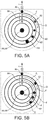
- FIG. 5E A specific example of the code 74 for the first embodiment of the preparation machine 4, is illustrated in figure 5E , wherein: the first, third and fourth reference positions 86 have a data unit 82 that encodes a parameter without any metadata the; second reference position 84 has three data units 82, each encoding a parameter, the parameter having metadata encoded according to a combination of the first and second embodiment (i.e. 3 values for the size of the unit and 3 values for the position of the unit, hence a total of 9 possible values of the metadata).
- the first reference position 84 encodes a percentage cooling power to apply;
- the third and fourth reference positions 84 encode either of the radial angular velocity W1 and the gyration angular velocity W2;
- the second reference position encodes time, temperature, torque as the respective small, medium and large data units in particular positions, whereby these parameters represent triggers such that when a condition set by one of them is achieved then the phase encoded by the code 74 is compete.
- the code processing system 18 processes the code to determine the preparation information by: obtaining by means of the image capturing device 54 a digital image of the code; processing by means of the image processing device 56 digital data of the digital image to decode the preparation information; outputting by means of the output device 72 said decoded preparation information.
- Processing of the digital data comprises: locating the units 82, 86 in the code; identifying the reference units 86 and determining therefrom a reference line r ; determining for each data unit 82 a distance d along the encoding line D from the reference line r, each of which will be described sequentially.
- Locating the units 82, 86 in the code is generally achieved by conversion of the pixels represented in the digital data to a one-bit bi-tonal black and white image, i.e. a binary image, whereby the associated conversion parameters are set to distinguish the units from their surrounding base level.
- a binary image i.e. a binary image
- an oversampled binary image sensor may be used as the image capturing device 54 to provide the binary image.
- Locations of the centre of units may be determined by a feature extraction technique such as circle Hough Transform. Different sized units may be identified by pixel integration.
- Identification of the reference units 86 and determining therefrom a reference line r is generally achieved by identification of one or a combination of: units that have a linear arrangement; units that are a predetermined and/or greatest distance apart; units that are a particular shape or size.
- An orientation identifier 88 of the reference line r can be determined by: a reference unit 86 that is a difference shape or size from the other reference units; a reference unit 86 that does not have associated therewith a data unit 82 on an encoding line D.
- the reference line r is determined by identifying a reference unit corresponding to the orientation identifier 88 that is arranged at a centre of a circle defined by the circular extending encoding lines D and determining a reference unit with a predetermined/greatest therefrom.
- Determining for each data unit 82 a distance d along the encoding line D from the associated reference position 84 of the reference line r may be achieved by determining the circumferential distance from the centre of a data unit 82 to the associated reference position 84, (e.g. by the product of: an angle in radians at the reference position 88 between the reference line r and a radial line to the data unit 82; and the overall circumference of the encoding line D ).
- determining said distance d may comprise determining an angular distance, i.e.
- the radial distance may be used to identify the data unit with respect to a reference position.
- the latter is preferably since less processing steps are required, moreover the precise radial distance is not required such that compensation for optional metadata encoding is obviated.
- the determined distance can be corrected using the magnification and/or distance of the image capturing device 54 away from the code 74 when the image was captured.
- V p of the parameter associated with the determined distance d stored information can be utilised that defines a relationship between the parameter and distance d.
- This step may be performed at the image processing device 56 or processor 38.
- the relationship may be linear, e.g. V p ⁇ d. Alternatively it may be non-linear.
- a non-linear relationship may comprise a logarithmic relationship, e.g. V p ⁇ log( d) or an exponential relationship, e.g. V p ⁇ e d .
- Such a relationship is particular advantageous when the accuracy of a parameter is important at low values and less important at high values or the converse e.g. for the first embodiment of the preparation machine 4 the accuracy of the angular velocities W1, W2 of the mixing unit is more important at a low angular velocity than at a high angular velocity, hence a logarithmic relationship is preferable.
- the accuracy of the determined distance d is less proximate the said centre.
- the parameters that require a higher level of precision can be arranged distal said centre and those that do not require a high level of precision can be arranged proximal said centre.
- the aforesaid metadata about the parameter can be determined depending on the embodiment of encoding, e.g.: in the first example by determining for the associated data unit 82 a unit length by feature extraction or overall area by pixel integration; in the second example by determining for the associated data unit 82 an offset to the encoding line D by feature extraction; in the third and fourth example by determining the centre of the associated data units by feature extraction.
- An attachment 94 may comprise the afore-described code 74 arranged on a surface thereof, the attachment 94 configured for attachment to the afore-described beverage or foodstuff preparation machine 4.
- the attachment comprises: a carrier 96 for carrying the code 74; an attachment member 98 for attachment of the carrier 96 to the machine 4 between an image capturing device 54 of said machine 4 and a container 6 received by said machine 4 and proximate said container. In this way an image of the code 74 can be captured by the image capturing device 54 as if it were attached to the container 6.
- suitable attachment members comprise: extensions attached to said carrier comprising an adhesive strip (as illustrated); a mechanical fastener such as a clip, bolt or bracket.
- An alternate attachment 100 may comprise the afore-described code 74, arranged on a surface thereof, the attachment 100 configured for attachment to the afore-described container 6.
- the attachment 100 comprises: a carrier 96 for carrying of the code 74; an attachment member 98 for attachment of the carrier 96 to the container 6.
- suitable attachment members comprise: an adhesive strip (as illustrated); a mechanical fastener such as a clip, bolt or bracket.
Landscapes
- Engineering & Computer Science (AREA)
- Mechanical Engineering (AREA)
- Food Science & Technology (AREA)
- Physics & Mathematics (AREA)
- General Physics & Mathematics (AREA)
- Theoretical Computer Science (AREA)
- Apparatus For Making Beverages (AREA)
- Details Of Rigid Or Semi-Rigid Containers (AREA)
- General Preparation And Processing Of Foods (AREA)
- Packging For Living Organisms, Food Or Medicinal Products That Are Sensitive To Environmental Conditiond (AREA)
Priority Applications (2)
| Application Number | Priority Date | Filing Date | Title |
|---|---|---|---|
| PL16707015T PL3265402T3 (pl) | 2015-04-30 | 2016-02-23 | Kod i pojemnik systemu do przyrządzania napojów lub żywności |
| EP18177642.8A EP3406542A1 (en) | 2015-04-30 | 2016-02-23 | Code and container of system for preparing a beverage or foodstuff |
Applications Claiming Priority (2)
| Application Number | Priority Date | Filing Date | Title |
|---|---|---|---|
| EP15165924 | 2015-04-30 | ||
| PCT/EP2016/053729 WO2016173735A1 (en) | 2015-04-30 | 2016-02-23 | Code and container of system for preparing a beverage or foodstuff |
Related Child Applications (2)
| Application Number | Title | Priority Date | Filing Date |
|---|---|---|---|
| EP18177642.8A Division-Into EP3406542A1 (en) | 2015-04-30 | 2016-02-23 | Code and container of system for preparing a beverage or foodstuff |
| EP18177642.8A Division EP3406542A1 (en) | 2015-04-30 | 2016-02-23 | Code and container of system for preparing a beverage or foodstuff |
Publications (2)
| Publication Number | Publication Date |
|---|---|
| EP3265402A1 EP3265402A1 (en) | 2018-01-10 |
| EP3265402B1 true EP3265402B1 (en) | 2018-12-26 |
Family
ID=53016548
Family Applications (2)
| Application Number | Title | Priority Date | Filing Date |
|---|---|---|---|
| EP16707015.0A Active EP3265402B1 (en) | 2015-04-30 | 2016-02-23 | Code and container of system for preparing a beverage or foodstuff |
| EP18177642.8A Withdrawn EP3406542A1 (en) | 2015-04-30 | 2016-02-23 | Code and container of system for preparing a beverage or foodstuff |
Family Applications After (1)
| Application Number | Title | Priority Date | Filing Date |
|---|---|---|---|
| EP18177642.8A Withdrawn EP3406542A1 (en) | 2015-04-30 | 2016-02-23 | Code and container of system for preparing a beverage or foodstuff |
Country Status (21)
| Country | Link |
|---|---|
| US (1) | US10827875B2 (pt) |
| EP (2) | EP3265402B1 (pt) |
| JP (1) | JP6959867B2 (pt) |
| KR (1) | KR102622508B1 (pt) |
| CN (1) | CN107531401B (pt) |
| AU (1) | AU2016254083B9 (pt) |
| BR (1) | BR112017022802B1 (pt) |
| CA (1) | CA2982008A1 (pt) |
| CL (1) | CL2017002704A1 (pt) |
| DK (1) | DK3265402T3 (pt) |
| ES (1) | ES2712976T3 (pt) |
| HU (1) | HUE043800T2 (pt) |
| MX (1) | MX2017013182A (pt) |
| MY (1) | MY189258A (pt) |
| PH (1) | PH12017501904A1 (pt) |
| PL (1) | PL3265402T3 (pt) |
| PT (1) | PT3265402T (pt) |
| SG (1) | SG11201707806SA (pt) |
| TR (1) | TR201901686T4 (pt) |
| WO (1) | WO2016173735A1 (pt) |
| ZA (1) | ZA201708110B (pt) |
Families Citing this family (24)
| Publication number | Priority date | Publication date | Assignee | Title |
|---|---|---|---|---|
| US10722066B2 (en) * | 2010-12-04 | 2020-07-28 | Adrian Rivera | Windowed single serving brewing material holder |
| US11832755B2 (en) * | 2007-07-13 | 2023-12-05 | Adrian Rivera | Brewing material container for a beverage brewer |
| HUE048822T2 (hu) * | 2010-07-22 | 2020-08-28 | K Fee System Gmbh | Adagkapszula vonalkóddal |
| MX2017013630A (es) | 2015-04-30 | 2018-03-08 | Nestec Sa | Arreglo de codigos y contenedor de un sistema para preparar una bebida o producto alimenticio. |
| TWI721084B (zh) * | 2016-02-23 | 2021-03-11 | 瑞士商雀巢製品股份有限公司 | 用於飲料或食品製備機器之容器、經組態以用於附接至該容器之附接件、飲料或食品製備系統、經組態以用於附接至該機器之附接件、編碼製備資訊之方法、製備該飲料或食品之方法、代碼用於在該容器上編碼製備資訊之用途及電腦程式產品 |
| TWI788279B (zh) * | 2016-02-23 | 2023-01-01 | 瑞士商雀巢製品股份有限公司 | 用於製備一飲料或食品之系統的代碼、方法與容器,用於編碼製備資訊之代碼與方法,及包含電腦程式之非暫時性電腦可讀取媒體 |
| US11399652B2 (en) | 2016-12-29 | 2022-08-02 | Koninklijke Philips N.V. | Method and device for providing a coffee beverage with reduced terpene content |
| MX2020001107A (es) * | 2017-07-28 | 2020-10-28 | Coca Cola Co | Método y aparato para codificar y descodificar códigos simbólicos circulares. |
| BR112020000116A2 (pt) * | 2017-08-08 | 2020-07-07 | Société des Produits Nestlé S.A. | recipiente com um código que codifica uma sequência de operações de preparação de alimento ou bebida |
| JP2019131209A (ja) * | 2018-01-29 | 2019-08-08 | パナソニックIpマネジメント株式会社 | 飲料提供システム、飲料提供方法、飲料提供プログラム |
| AU2019239317A1 (en) * | 2018-03-22 | 2020-11-12 | Bedford Systems Llc | Beverage appliance with POD recognition system |
| KR102273369B1 (ko) | 2018-12-14 | 2021-07-05 | 숙명여자대학교산학협력단 | 응급의료기관 종에 따른 응급실 혼잡도 예측 방법 |
| GB2587321B (en) * | 2019-08-15 | 2023-06-07 | Douwe Egberts Bv | Beverage ingredient containers, methods of making and methods of using the same |
| US11805934B1 (en) * | 2020-10-21 | 2023-11-07 | Adrian Rivera | Brewing material lid and container for a beverage brewer |
| US11647860B1 (en) | 2022-05-13 | 2023-05-16 | Sharkninja Operating Llc | Flavored beverage carbonation system |
| US11751585B1 (en) | 2022-05-13 | 2023-09-12 | Sharkninja Operating Llc | Flavored beverage carbonation system |
| WO2024094786A1 (en) | 2022-11-04 | 2024-05-10 | Société des Produits Nestlé S.A. | Beverage or foodstuff preparation system |
| WO2024100077A1 (en) | 2022-11-10 | 2024-05-16 | Société des Produits Nestlé S.A. | Beverage or foodstuff preparation system |
| US11745996B1 (en) | 2022-11-17 | 2023-09-05 | Sharkninja Operating Llc | Ingredient containers for use with beverage dispensers |
| US11634314B1 (en) | 2022-11-17 | 2023-04-25 | Sharkninja Operating Llc | Dosing accuracy |
| US11738988B1 (en) | 2022-11-17 | 2023-08-29 | Sharkninja Operating Llc | Ingredient container valve control |
| US11871867B1 (en) | 2023-03-22 | 2024-01-16 | Sharkninja Operating Llc | Additive container with bottom cover |
| US11925287B1 (en) | 2023-03-22 | 2024-03-12 | Sharkninja Operating Llc | Additive container with inlet tube |
| US11931704B1 (en) | 2023-06-16 | 2024-03-19 | Sharkninja Operating Llc | Carbonation chamber |
Family Cites Families (38)
| Publication number | Priority date | Publication date | Assignee | Title |
|---|---|---|---|---|
| JP3600916B2 (ja) * | 1993-08-04 | 2004-12-15 | 庸良 落合 | ビックバンコード読み取り器 |
| US5637849A (en) * | 1995-05-31 | 1997-06-10 | Metanetics Corporation | Maxicode data extraction using spatial domain features |
| WO2002028241A1 (en) | 2000-10-06 | 2002-04-11 | Boyd Coffee Company | Encoded coffee packet |
| KR100964514B1 (ko) | 2002-01-16 | 2010-06-21 | 소시에떼 데 프로듀이 네슬레 소시에떼아노님 | 개방 수단을 갖춘 밀폐 캡슐 |
| ES2360920T3 (es) | 2004-08-23 | 2011-06-10 | Nestec S.A. | Cápsula para preparar y distribuir una bebida mediante la inyección de un fluido presurizado en la cápsula. |
| CA2640153A1 (en) * | 2006-01-27 | 2007-08-09 | Spyder Lynk, Llc | Encoding and decoding data in an image |
| US8194914B1 (en) * | 2006-10-19 | 2012-06-05 | Spyder Lynk, Llc | Encoding and decoding data into an image using identifiable marks and encoded elements |
| SI2071986T1 (sl) | 2007-12-18 | 2012-04-30 | Nestec Sa | Sistem za pripravo napitka iz sestavin, podprt s kodiranim vloĹľkom |
| US20100078480A1 (en) * | 2008-09-29 | 2010-04-01 | Symbol Technologies, Inc. | Method of positioning the barcode |
| ES2436546T3 (es) | 2009-02-06 | 2014-01-02 | Nestec S.A. | Dispositivo y procedimiento que utilizan centrifugación para extraer un líquido y medios de compensación de la pérdida de calor |
| DK2448843T3 (da) * | 2009-07-03 | 2013-03-25 | Nestec Sa | Kapsel til tilberedningen af en drik omfattende et identifikationselement og driktilberedningsindretning dertil |
| IN2012DN00761A (pt) | 2009-08-28 | 2015-05-22 | Nestec Sa | |
| KR20120112498A (ko) | 2009-12-08 | 2012-10-11 | 네스텍 소시에테아노님 | 유동 조절 수단을 구비한 캡슐 시스템 |
| EP2345351A1 (en) | 2010-01-19 | 2011-07-20 | Nestec S.A. | Capsule for the preparation of a beverage comprising an identification code |
| JP5870039B2 (ja) | 2010-02-08 | 2016-02-24 | ネステク ソシエテ アノニム | 飲料生成装置内での遠心処理によりコーヒー飲料を供給するための方法 |
| JP4625139B1 (ja) | 2010-06-03 | 2011-02-02 | 傳生 西▲崎▼ | 情報表現方法、情報表現パターンが形成された物品、情報出力装置、及び、情報表現装置 |
| KR101796943B1 (ko) * | 2010-06-03 | 2017-11-13 | 츠타오 니시자키 | 정보 표현 방법, 정보 표현 패턴이 형성된 물품, 정보 출력 장치, 및 정보 표현 장치 |
| GB2481142B (en) * | 2010-06-11 | 2015-08-12 | Rnib | Coded information systems |
| US9332877B2 (en) | 2010-06-11 | 2016-05-10 | Pressco Ip Llc | Cookware and cook-packs for narrowband irradiation cooking and systems and methods thereof |
| BR112012031585B1 (pt) | 2010-06-11 | 2020-11-10 | Pressco Ip Llc | recipiente para cozinhar e pacote de cozimento |
| SG186283A1 (en) | 2010-06-14 | 2013-01-30 | Trutag Technologies Inc | System for producing a packaged item with an identifier |
| US8960075B2 (en) | 2010-09-07 | 2015-02-24 | Helmut Traitler | Dispensing system and method |
| AU2011328110B2 (en) | 2010-11-11 | 2016-07-21 | Société des Produits Nestlé S.A. | Capsule, beverage production machine and system for the preparation of a nutritional product |
| GB2485575B (en) | 2010-11-18 | 2013-05-15 | Kraft Foods R & D Inc | Apparatus and methods relating to dispensation from beverage machines |
| PT2481330E (pt) | 2011-02-01 | 2013-06-04 | Nestec Sa | Código de barras para uma cápsula de preparação de bebidas |
| EP3381337A1 (en) | 2011-03-14 | 2018-10-03 | Nestec S.A. | Automatic beverage machine |
| ES2471874T3 (es) | 2011-11-16 | 2014-06-27 | Nestec S.A. | Soporte y cápsula para preparar una bebida mediante centrifugaci�n, sistema y método para preparar una bebida mediante centrifugaci�n |
| GB2499201B (en) | 2012-02-07 | 2014-07-02 | Kraft Foods R & D Inc | A beverage preparation system, a coded insert and methods of use thereof |
| WO2014043652A1 (en) * | 2012-09-15 | 2014-03-20 | Deepak Boggavarapu | Systems and methods for coffee preparation |
| EP2936381A1 (en) * | 2012-12-21 | 2015-10-28 | Nestec S.A. | Food or beverage production system |
| AU2014217787B2 (en) | 2013-02-18 | 2017-07-27 | Société des Produits Nestlé S.A. | Packs for preparing beverages |
| HUE031937T2 (en) | 2013-06-24 | 2017-08-28 | Nestec Sa | Capsules for the preparation of consumable preparations |
| EP2853182B1 (en) * | 2013-09-30 | 2016-10-26 | Nestec S.A. | Code support and capsule for preparing a beverage by centrifugation, system and method for preparing a beverage by centrifugation |
| SG2013075338A (en) | 2013-10-08 | 2015-05-28 | K One Ind Pte Ltd | Set meal preparation system |
| US10053280B2 (en) | 2013-12-30 | 2018-08-21 | Elwha Llc | Systems and methods for providing customized packagings for customized food items that were customized based, at least in part, on customized food item integrity preference |
| WO2015195985A1 (en) | 2014-06-18 | 2015-12-23 | Serenete Corporation | Modularized food preparation device and tray structure for use thereof |
| CN107529914B (zh) | 2015-04-30 | 2020-04-07 | 雀巢产品有限公司 | 用于制备饮料或食品的系统的代码和容器 |
| MX2017013630A (es) | 2015-04-30 | 2018-03-08 | Nestec Sa | Arreglo de codigos y contenedor de un sistema para preparar una bebida o producto alimenticio. |
-
2016
- 2016-02-23 ES ES16707015T patent/ES2712976T3/es active Active
- 2016-02-23 MY MYPI2017703537A patent/MY189258A/en unknown
- 2016-02-23 CN CN201680024308.7A patent/CN107531401B/zh active Active
- 2016-02-23 SG SG11201707806SA patent/SG11201707806SA/en unknown
- 2016-02-23 HU HUE16707015A patent/HUE043800T2/hu unknown
- 2016-02-23 MX MX2017013182A patent/MX2017013182A/es unknown
- 2016-02-23 AU AU2016254083A patent/AU2016254083B9/en active Active
- 2016-02-23 PL PL16707015T patent/PL3265402T3/pl unknown
- 2016-02-23 JP JP2017555666A patent/JP6959867B2/ja active Active
- 2016-02-23 BR BR112017022802-5A patent/BR112017022802B1/pt active IP Right Grant
- 2016-02-23 TR TR2019/01686T patent/TR201901686T4/tr unknown
- 2016-02-23 WO PCT/EP2016/053729 patent/WO2016173735A1/en active Application Filing
- 2016-02-23 KR KR1020177030998A patent/KR102622508B1/ko active IP Right Grant
- 2016-02-23 EP EP16707015.0A patent/EP3265402B1/en active Active
- 2016-02-23 PT PT16707015T patent/PT3265402T/pt unknown
- 2016-02-23 US US15/565,469 patent/US10827875B2/en active Active
- 2016-02-23 DK DK16707015.0T patent/DK3265402T3/en active
- 2016-02-23 CA CA2982008A patent/CA2982008A1/en active Pending
- 2016-02-23 EP EP18177642.8A patent/EP3406542A1/en not_active Withdrawn
-
2017
- 2017-10-18 PH PH12017501904A patent/PH12017501904A1/en unknown
- 2017-10-25 CL CL2017002704A patent/CL2017002704A1/es unknown
- 2017-11-29 ZA ZA2017/08110A patent/ZA201708110B/en unknown
Non-Patent Citations (1)
| Title |
|---|
| None * |
Also Published As
| Publication number | Publication date |
|---|---|
| CN107531401A (zh) | 2018-01-02 |
| CL2017002704A1 (es) | 2018-03-23 |
| JP6959867B2 (ja) | 2021-11-05 |
| AU2016254083A1 (en) | 2017-10-12 |
| AU2016254083B9 (en) | 2020-07-16 |
| ES2712976T3 (es) | 2019-05-17 |
| JP2018517622A (ja) | 2018-07-05 |
| KR102622508B1 (ko) | 2024-01-08 |
| ZA201708110B (en) | 2022-11-30 |
| EP3265402A1 (en) | 2018-01-10 |
| BR112017022802B1 (pt) | 2022-07-26 |
| CA2982008A1 (en) | 2016-11-03 |
| PT3265402T (pt) | 2019-03-25 |
| PH12017501904B1 (en) | 2018-03-05 |
| AU2016254083B2 (en) | 2020-06-11 |
| DK3265402T3 (en) | 2019-03-25 |
| MY189258A (en) | 2022-01-31 |
| KR20180004123A (ko) | 2018-01-10 |
| MX2017013182A (es) | 2018-01-16 |
| WO2016173735A1 (en) | 2016-11-03 |
| EP3406542A1 (en) | 2018-11-28 |
| PH12017501904A1 (en) | 2018-03-05 |
| US20180125288A1 (en) | 2018-05-10 |
| SG11201707806SA (en) | 2017-11-29 |
| BR112017022802A2 (pt) | 2018-07-17 |
| TR201901686T4 (tr) | 2019-02-21 |
| PL3265402T3 (pl) | 2019-06-28 |
| HUE043800T2 (hu) | 2019-09-30 |
| US10827875B2 (en) | 2020-11-10 |
| CN107531401B (zh) | 2020-06-16 |
Similar Documents
| Publication | Publication Date | Title |
|---|---|---|
| EP3265402B1 (en) | Code and container of system for preparing a beverage or foodstuff | |
| US10820746B2 (en) | Code arrangement and container of system for preparing a beverage or foodstuff | |
| EP3288863B1 (en) | Code and container of system for preparing a beverage or foodstuff | |
| AU2017224473B2 (en) | Recipcode and container of system for preparing a beverage or foodstuff | |
| EP3288862B1 (en) | Code and container of system for preparing a beverage or foodstuff | |
| IL260388B (en) | A container of a system for preparing a drink or an edible item | |
| WO2017144581A1 (en) | Code and container of system for preparing a beverage or foodstuff | |
| EP3420498A1 (en) | Code and container of system for preparing a beverage or foodstuff | |
| EP3420497B1 (en) | Code and container of system for preparing a beverage or foodstuff | |
| WO2017144580A1 (en) | Code and container of system for preparing a beverage or foodstuff |
Legal Events
| Date | Code | Title | Description |
|---|---|---|---|
| STAA | Information on the status of an ep patent application or granted ep patent |
Free format text: STATUS: THE INTERNATIONAL PUBLICATION HAS BEEN MADE |
|
| PUAI | Public reference made under article 153(3) epc to a published international application that has entered the european phase |
Free format text: ORIGINAL CODE: 0009012 |
|
| STAA | Information on the status of an ep patent application or granted ep patent |
Free format text: STATUS: REQUEST FOR EXAMINATION WAS MADE |
|
| 17P | Request for examination filed |
Effective date: 20171002 |
|
| AK | Designated contracting states |
Kind code of ref document: A1 Designated state(s): AL AT BE BG CH CY CZ DE DK EE ES FI FR GB GR HR HU IE IS IT LI LT LU LV MC MK MT NL NO PL PT RO RS SE SI SK SM TR |
|
| AX | Request for extension of the european patent |
Extension state: BA ME |
|
| GRAP | Despatch of communication of intention to grant a patent |
Free format text: ORIGINAL CODE: EPIDOSNIGR1 |
|
| STAA | Information on the status of an ep patent application or granted ep patent |
Free format text: STATUS: GRANT OF PATENT IS INTENDED |
|
| DAV | Request for validation of the european patent (deleted) | ||
| DAX | Request for extension of the european patent (deleted) | ||
| INTG | Intention to grant announced |
Effective date: 20180604 |
|
| GRAS | Grant fee paid |
Free format text: ORIGINAL CODE: EPIDOSNIGR3 |
|
| GRAA | (expected) grant |
Free format text: ORIGINAL CODE: 0009210 |
|
| STAA | Information on the status of an ep patent application or granted ep patent |
Free format text: STATUS: THE PATENT HAS BEEN GRANTED |
|
| AK | Designated contracting states |
Kind code of ref document: B1 Designated state(s): AL AT BE BG CH CY CZ DE DK EE ES FI FR GB GR HR HU IE IS IT LI LT LU LV MC MK MT NL NO PL PT RO RS SE SI SK SM TR |
|
| REG | Reference to a national code |
Ref country code: GB Ref legal event code: FG4D |
|
| REG | Reference to a national code |
Ref country code: CH Ref legal event code: EP |
|
| REG | Reference to a national code |
Ref country code: AT Ref legal event code: REF Ref document number: 1081105 Country of ref document: AT Kind code of ref document: T Effective date: 20190115 |
|
| REG | Reference to a national code |
Ref country code: DE Ref legal event code: R096 Ref document number: 602016008716 Country of ref document: DE |
|
| REG | Reference to a national code |
Ref country code: IE Ref legal event code: FG4D |
|
| REG | Reference to a national code |
Ref country code: DK Ref legal event code: T3 Effective date: 20190318 Ref country code: RO Ref legal event code: EPE Ref country code: PT Ref legal event code: SC4A Ref document number: 3265402 Country of ref document: PT Date of ref document: 20190325 Kind code of ref document: T Free format text: AVAILABILITY OF NATIONAL TRANSLATION Effective date: 20190312 |
|
| REG | Reference to a national code |
Ref country code: NO Ref legal event code: T2 Effective date: 20181226 |
|
| REG | Reference to a national code |
Ref country code: SE Ref legal event code: TRGR |
|
| REG | Reference to a national code |
Ref country code: NL Ref legal event code: FP |
|
| PG25 | Lapsed in a contracting state [announced via postgrant information from national office to epo] |
Ref country code: LV Free format text: LAPSE BECAUSE OF FAILURE TO SUBMIT A TRANSLATION OF THE DESCRIPTION OR TO PAY THE FEE WITHIN THE PRESCRIBED TIME-LIMIT Effective date: 20181226 Ref country code: HR Free format text: LAPSE BECAUSE OF FAILURE TO SUBMIT A TRANSLATION OF THE DESCRIPTION OR TO PAY THE FEE WITHIN THE PRESCRIBED TIME-LIMIT Effective date: 20181226 Ref country code: BG Free format text: LAPSE BECAUSE OF FAILURE TO SUBMIT A TRANSLATION OF THE DESCRIPTION OR TO PAY THE FEE WITHIN THE PRESCRIBED TIME-LIMIT Effective date: 20190326 Ref country code: LT Free format text: LAPSE BECAUSE OF FAILURE TO SUBMIT A TRANSLATION OF THE DESCRIPTION OR TO PAY THE FEE WITHIN THE PRESCRIBED TIME-LIMIT Effective date: 20181226 |
|
| REG | Reference to a national code |
Ref country code: LT Ref legal event code: MG4D |
|
| REG | Reference to a national code |
Ref country code: ES Ref legal event code: FG2A Ref document number: 2712976 Country of ref document: ES Kind code of ref document: T3 Effective date: 20190517 |
|
| PG25 | Lapsed in a contracting state [announced via postgrant information from national office to epo] |
Ref country code: AL Free format text: LAPSE BECAUSE OF FAILURE TO SUBMIT A TRANSLATION OF THE DESCRIPTION OR TO PAY THE FEE WITHIN THE PRESCRIBED TIME-LIMIT Effective date: 20181226 Ref country code: RS Free format text: LAPSE BECAUSE OF FAILURE TO SUBMIT A TRANSLATION OF THE DESCRIPTION OR TO PAY THE FEE WITHIN THE PRESCRIBED TIME-LIMIT Effective date: 20181226 |
|
| REG | Reference to a national code |
Ref country code: GR Ref legal event code: EP Ref document number: 20190400846 Country of ref document: GR Effective date: 20190524 |
|
| REG | Reference to a national code |
Ref country code: NL Ref legal event code: PD Owner name: SOCIETE DES PRODUITS NESTLE S.A.; CH Free format text: DETAILS ASSIGNMENT: CHANGE OF OWNER(S), MERGE; FORMER OWNER NAME: NESTEC S.A. Effective date: 20190620 |
|
| REG | Reference to a national code |
Ref country code: NO Ref legal event code: CHAD Owner name: SOCIETE DES PRODUITS NESTLE S.A., CH Ref country code: NO Ref legal event code: CREP Representative=s name: BRYN AARFLOT AS, STORTINGSGATA 8, 0161 OSLO, NORGE |
|
| RAP2 | Party data changed (patent owner data changed or rights of a patent transferred) |
Owner name: SOCIETE DES PRODUITS NESTLE S.A. |
|
| REG | Reference to a national code |
Ref country code: CH Ref legal event code: PCOW |
|
| REG | Reference to a national code |
Ref country code: GB Ref legal event code: 732E Free format text: REGISTERED BETWEEN 20190801 AND 20190807 |
|
| PG25 | Lapsed in a contracting state [announced via postgrant information from national office to epo] |
Ref country code: SK Free format text: LAPSE BECAUSE OF FAILURE TO SUBMIT A TRANSLATION OF THE DESCRIPTION OR TO PAY THE FEE WITHIN THE PRESCRIBED TIME-LIMIT Effective date: 20181226 Ref country code: EE Free format text: LAPSE BECAUSE OF FAILURE TO SUBMIT A TRANSLATION OF THE DESCRIPTION OR TO PAY THE FEE WITHIN THE PRESCRIBED TIME-LIMIT Effective date: 20181226 Ref country code: SM Free format text: LAPSE BECAUSE OF FAILURE TO SUBMIT A TRANSLATION OF THE DESCRIPTION OR TO PAY THE FEE WITHIN THE PRESCRIBED TIME-LIMIT Effective date: 20181226 Ref country code: IS Free format text: LAPSE BECAUSE OF FAILURE TO SUBMIT A TRANSLATION OF THE DESCRIPTION OR TO PAY THE FEE WITHIN THE PRESCRIBED TIME-LIMIT Effective date: 20190426 |
|
| REG | Reference to a national code |
Ref country code: DE Ref legal event code: R097 Ref document number: 602016008716 Country of ref document: DE |
|
| REG | Reference to a national code |
Ref country code: HU Ref legal event code: AG4A Ref document number: E043800 Country of ref document: HU Ref country code: HU Ref legal event code: FH1C Free format text: FORMER REPRESENTATIVE(S): DANUBIA SZABADALMI ES JOGI IRODA KFT., HU Representative=s name: DR. KOCSOMBA NELLI UEGYVEDI IRODA, HU Ref country code: HU Ref legal event code: GB9C Owner name: SOCIETE DES PRODUITS S.A., CH Free format text: FORMER OWNER(S): NESTEC S.A., CH |
|
| PG25 | Lapsed in a contracting state [announced via postgrant information from national office to epo] |
Ref country code: MC Free format text: LAPSE BECAUSE OF FAILURE TO SUBMIT A TRANSLATION OF THE DESCRIPTION OR TO PAY THE FEE WITHIN THE PRESCRIBED TIME-LIMIT Effective date: 20181226 Ref country code: LU Free format text: LAPSE BECAUSE OF NON-PAYMENT OF DUE FEES Effective date: 20190223 |
|
| PLBE | No opposition filed within time limit |
Free format text: ORIGINAL CODE: 0009261 |
|
| STAA | Information on the status of an ep patent application or granted ep patent |
Free format text: STATUS: NO OPPOSITION FILED WITHIN TIME LIMIT |
|
| REG | Reference to a national code |
Ref country code: AT Ref legal event code: PC Ref document number: 1081105 Country of ref document: AT Kind code of ref document: T Owner name: SOCIETE DES PRODUITS NESTLE S.A., CH Effective date: 20190916 |
|
| REG | Reference to a national code |
Ref country code: BE Ref legal event code: PD Owner name: SOCIETE DES PRODUITS NESTLE S.A.; CH Free format text: DETAILS ASSIGNMENT: CHANGE OF OWNER(S), CESSION; FORMER OWNER NAME: NESTEC S.A. Effective date: 20190712 |
|
| 26N | No opposition filed |
Effective date: 20190927 |
|
| REG | Reference to a national code |
Ref country code: NO Ref legal event code: CREP Representative=s name: PLOUGMANN VINGTOFT, POSTBOKS 1003 SENTRUM, 0104 |
|
| REG | Reference to a national code |
Ref country code: DE Ref legal event code: R082 Ref document number: 602016008716 Country of ref document: DE Representative=s name: MITSCHERLICH, PATENT- UND RECHTSANWAELTE PARTM, DE Ref country code: DE Ref legal event code: R081 Ref document number: 602016008716 Country of ref document: DE Owner name: SOCIETE DES PRODUITS NESTLE S.A., CH Free format text: FORMER OWNER: NESTEC S.A., VEVEY, CH |
|
| PG25 | Lapsed in a contracting state [announced via postgrant information from national office to epo] |
Ref country code: SI Free format text: LAPSE BECAUSE OF FAILURE TO SUBMIT A TRANSLATION OF THE DESCRIPTION OR TO PAY THE FEE WITHIN THE PRESCRIBED TIME-LIMIT Effective date: 20181226 |
|
| PG25 | Lapsed in a contracting state [announced via postgrant information from national office to epo] |
Ref country code: MT Free format text: LAPSE BECAUSE OF NON-PAYMENT OF DUE FEES Effective date: 20190223 |
|
| PG25 | Lapsed in a contracting state [announced via postgrant information from national office to epo] |
Ref country code: CY Free format text: LAPSE BECAUSE OF FAILURE TO SUBMIT A TRANSLATION OF THE DESCRIPTION OR TO PAY THE FEE WITHIN THE PRESCRIBED TIME-LIMIT Effective date: 20181226 |
|
| PG25 | Lapsed in a contracting state [announced via postgrant information from national office to epo] |
Ref country code: MK Free format text: LAPSE BECAUSE OF FAILURE TO SUBMIT A TRANSLATION OF THE DESCRIPTION OR TO PAY THE FEE WITHIN THE PRESCRIBED TIME-LIMIT Effective date: 20181226 |
|
| REG | Reference to a national code |
Ref country code: HU Ref legal event code: HC9C Owner name: SOCIETE DES PRODUITS NESTLE S.A., CH Free format text: FORMER OWNER(S): NESTEC S.A., CH |
|
| PGFP | Annual fee paid to national office [announced via postgrant information from national office to epo] |
Ref country code: SE Payment date: 20221212 Year of fee payment: 8 |
|
| PGFP | Annual fee paid to national office [announced via postgrant information from national office to epo] |
Ref country code: PL Payment date: 20221213 Year of fee payment: 8 |
|
| REG | Reference to a national code |
Ref country code: AT Ref legal event code: UEP Ref document number: 1081105 Country of ref document: AT Kind code of ref document: T Effective date: 20181226 |
|
| PGFP | Annual fee paid to national office [announced via postgrant information from national office to epo] |
Ref country code: NO Payment date: 20230208 Year of fee payment: 8 Ref country code: DK Payment date: 20230213 Year of fee payment: 8 |
|
| PGFP | Annual fee paid to national office [announced via postgrant information from national office to epo] |
Ref country code: TR Payment date: 20230222 Year of fee payment: 8 Ref country code: IT Payment date: 20230110 Year of fee payment: 8 Ref country code: BE Payment date: 20230117 Year of fee payment: 8 |
|
| P01 | Opt-out of the competence of the unified patent court (upc) registered |
Effective date: 20230527 |
|
| PGFP | Annual fee paid to national office [announced via postgrant information from national office to epo] |
Ref country code: FR Payment date: 20231229 Year of fee payment: 9 |
|
| PGFP | Annual fee paid to national office [announced via postgrant information from national office to epo] |
Ref country code: NL Payment date: 20240108 Year of fee payment: 9 |
|
| PGFP | Annual fee paid to national office [announced via postgrant information from national office to epo] |
Ref country code: GR Payment date: 20240110 Year of fee payment: 9 |
|
| PGFP | Annual fee paid to national office [announced via postgrant information from national office to epo] |
Ref country code: IE Payment date: 20240103 Year of fee payment: 9 Ref country code: ES Payment date: 20240307 Year of fee payment: 9 |
|
| PGFP | Annual fee paid to national office [announced via postgrant information from national office to epo] |
Ref country code: AT Payment date: 20240125 Year of fee payment: 9 |
|
| PGFP | Annual fee paid to national office [announced via postgrant information from national office to epo] |
Ref country code: RO Payment date: 20240129 Year of fee payment: 9 Ref country code: HU Payment date: 20240116 Year of fee payment: 9 Ref country code: FI Payment date: 20240213 Year of fee payment: 9 Ref country code: DE Payment date: 20231229 Year of fee payment: 9 Ref country code: CZ Payment date: 20240129 Year of fee payment: 9 Ref country code: CH Payment date: 20240301 Year of fee payment: 9 Ref country code: GB Payment date: 20240108 Year of fee payment: 9 Ref country code: PT Payment date: 20240221 Year of fee payment: 9 |