EP3265396B1 - Douille et couvercle de surbouchage pour celle-ci - Google Patents
Douille et couvercle de surbouchage pour celle-ci Download PDFInfo
- Publication number
- EP3265396B1 EP3265396B1 EP15884132.0A EP15884132A EP3265396B1 EP 3265396 B1 EP3265396 B1 EP 3265396B1 EP 15884132 A EP15884132 A EP 15884132A EP 3265396 B1 EP3265396 B1 EP 3265396B1
- Authority
- EP
- European Patent Office
- Prior art keywords
- fitment
- overcap
- spout
- sealing surface
- skirt
- Prior art date
- Legal status (The legal status is an assumption and is not a legal conclusion. Google has not performed a legal analysis and makes no representation as to the accuracy of the status listed.)
- Active
Links
- 238000007789 sealing Methods 0.000 claims description 51
- 230000000694 effects Effects 0.000 claims description 11
- 238000004891 communication Methods 0.000 claims description 8
- 239000007789 gas Substances 0.000 description 30
- 230000001954 sterilising effect Effects 0.000 description 22
- 238000004140 cleaning Methods 0.000 description 16
- 238000000034 method Methods 0.000 description 16
- 239000000463 material Substances 0.000 description 15
- 238000004659 sterilization and disinfection Methods 0.000 description 14
- MHAJPDPJQMAIIY-UHFFFAOYSA-N Hydrogen peroxide Chemical compound OO MHAJPDPJQMAIIY-UHFFFAOYSA-N 0.000 description 12
- 230000008569 process Effects 0.000 description 12
- 239000000945 filler Substances 0.000 description 11
- 230000002411 adverse Effects 0.000 description 10
- QVGXLLKOCUKJST-UHFFFAOYSA-N atomic oxygen Chemical compound [O] QVGXLLKOCUKJST-UHFFFAOYSA-N 0.000 description 9
- 238000009434 installation Methods 0.000 description 9
- 239000001301 oxygen Substances 0.000 description 9
- 229910052760 oxygen Inorganic materials 0.000 description 9
- -1 polyethylene Polymers 0.000 description 8
- 238000013461 design Methods 0.000 description 5
- 235000013305 food Nutrition 0.000 description 5
- 229920001169 thermoplastic Polymers 0.000 description 5
- 239000004698 Polyethylene Substances 0.000 description 4
- 239000002184 metal Substances 0.000 description 4
- 238000004806 packaging method and process Methods 0.000 description 4
- 229920000573 polyethylene Polymers 0.000 description 4
- 239000004416 thermosoftening plastic Substances 0.000 description 4
- 239000004743 Polypropylene Substances 0.000 description 3
- 230000004888 barrier function Effects 0.000 description 3
- 239000000356 contaminant Substances 0.000 description 3
- 210000003811 finger Anatomy 0.000 description 3
- 239000012530 fluid Substances 0.000 description 3
- 238000003780 insertion Methods 0.000 description 3
- 230000037431 insertion Effects 0.000 description 3
- 238000004519 manufacturing process Methods 0.000 description 3
- 238000000465 moulding Methods 0.000 description 3
- 229920001155 polypropylene Polymers 0.000 description 3
- 239000000126 substance Substances 0.000 description 3
- 239000012815 thermoplastic material Substances 0.000 description 3
- 230000009471 action Effects 0.000 description 2
- 230000035622 drinking Effects 0.000 description 2
- 239000003814 drug Substances 0.000 description 2
- 230000009977 dual effect Effects 0.000 description 2
- 230000006870 function Effects 0.000 description 2
- 229920001903 high density polyethylene Polymers 0.000 description 2
- 239000004700 high-density polyethylene Substances 0.000 description 2
- 230000013011 mating Effects 0.000 description 2
- 230000036961 partial effect Effects 0.000 description 2
- 230000035699 permeability Effects 0.000 description 2
- 239000000825 pharmaceutical preparation Substances 0.000 description 2
- 229940127557 pharmaceutical product Drugs 0.000 description 2
- 239000000088 plastic resin Substances 0.000 description 2
- 229920000139 polyethylene terephthalate Polymers 0.000 description 2
- 239000005020 polyethylene terephthalate Substances 0.000 description 2
- 230000002829 reductive effect Effects 0.000 description 2
- 210000003813 thumb Anatomy 0.000 description 2
- 235000013618 yogurt Nutrition 0.000 description 2
- 241001465754 Metazoa Species 0.000 description 1
- 239000000853 adhesive Substances 0.000 description 1
- 230000001070 adhesive effect Effects 0.000 description 1
- 230000004075 alteration Effects 0.000 description 1
- 239000011324 bead Substances 0.000 description 1
- 230000005540 biological transmission Effects 0.000 description 1
- 230000015572 biosynthetic process Effects 0.000 description 1
- 230000008859 change Effects 0.000 description 1
- 150000001875 compounds Chemical class 0.000 description 1
- 235000009508 confectionery Nutrition 0.000 description 1
- 238000010276 construction Methods 0.000 description 1
- 238000011109 contamination Methods 0.000 description 1
- 235000014510 cooky Nutrition 0.000 description 1
- 235000012495 crackers Nutrition 0.000 description 1
- 239000006071 cream Substances 0.000 description 1
- 230000003247 decreasing effect Effects 0.000 description 1
- 238000011161 development Methods 0.000 description 1
- 229940079593 drug Drugs 0.000 description 1
- 239000011888 foil Substances 0.000 description 1
- 239000002778 food additive Substances 0.000 description 1
- 235000013373 food additive Nutrition 0.000 description 1
- 235000013350 formula milk Nutrition 0.000 description 1
- 239000000499 gel Substances 0.000 description 1
- 239000008187 granular material Substances 0.000 description 1
- 238000001746 injection moulding Methods 0.000 description 1
- 230000001788 irregular Effects 0.000 description 1
- 230000009191 jumping Effects 0.000 description 1
- 239000007788 liquid Substances 0.000 description 1
- 239000006210 lotion Substances 0.000 description 1
- 238000012423 maintenance Methods 0.000 description 1
- 238000012986 modification Methods 0.000 description 1
- 230000004048 modification Effects 0.000 description 1
- 235000014571 nuts Nutrition 0.000 description 1
- 239000002245 particle Substances 0.000 description 1
- 239000006072 paste Substances 0.000 description 1
- 230000002093 peripheral effect Effects 0.000 description 1
- 239000000843 powder Substances 0.000 description 1
- 238000012545 processing Methods 0.000 description 1
- 238000011160 research Methods 0.000 description 1
- 230000000717 retained effect Effects 0.000 description 1
- 230000035807 sensation Effects 0.000 description 1
- 239000002002 slurry Substances 0.000 description 1
- 239000007787 solid Substances 0.000 description 1
- 238000013519 translation Methods 0.000 description 1
- 239000002699 waste material Substances 0.000 description 1
Images


Classifications
-
- B—PERFORMING OPERATIONS; TRANSPORTING
- B65—CONVEYING; PACKING; STORING; HANDLING THIN OR FILAMENTARY MATERIAL
- B65D—CONTAINERS FOR STORAGE OR TRANSPORT OF ARTICLES OR MATERIALS, e.g. BAGS, BARRELS, BOTTLES, BOXES, CANS, CARTONS, CRATES, DRUMS, JARS, TANKS, HOPPERS, FORWARDING CONTAINERS; ACCESSORIES, CLOSURES, OR FITTINGS THEREFOR; PACKAGING ELEMENTS; PACKAGES
- B65D41/00—Caps, e.g. crown caps or crown seals, i.e. members having parts arranged for engagement with the external periphery of a neck or wall defining a pouring opening or discharge aperture; Protective cap-like covers for closure members, e.g. decorative covers of metal foil or paper
- B65D41/32—Caps or cap-like covers with lines of weakness, tearing-strips, tags, or like opening or removal devices, e.g. to facilitate formation of pouring openings
- B65D41/34—Threaded or like caps or cap-like covers provided with tamper elements formed in, or attached to, the closure skirt
-
- B—PERFORMING OPERATIONS; TRANSPORTING
- B65—CONVEYING; PACKING; STORING; HANDLING THIN OR FILAMENTARY MATERIAL
- B65D—CONTAINERS FOR STORAGE OR TRANSPORT OF ARTICLES OR MATERIALS, e.g. BAGS, BARRELS, BOTTLES, BOXES, CANS, CARTONS, CRATES, DRUMS, JARS, TANKS, HOPPERS, FORWARDING CONTAINERS; ACCESSORIES, CLOSURES, OR FITTINGS THEREFOR; PACKAGING ELEMENTS; PACKAGES
- B65D41/00—Caps, e.g. crown caps or crown seals, i.e. members having parts arranged for engagement with the external periphery of a neck or wall defining a pouring opening or discharge aperture; Protective cap-like covers for closure members, e.g. decorative covers of metal foil or paper
- B65D41/02—Caps or cap-like covers without lines of weakness, tearing strips, tags, or like opening or removal devices
- B65D41/04—Threaded or like caps or cap-like covers secured by rotation
- B65D41/0407—Threaded or like caps or cap-like covers secured by rotation with integral sealing means
- B65D41/0414—Threaded or like caps or cap-like covers secured by rotation with integral sealing means formed by a plug, collar, flange, rib or the like contacting the internal surface of a container neck
- B65D41/0421—Threaded or like caps or cap-like covers secured by rotation with integral sealing means formed by a plug, collar, flange, rib or the like contacting the internal surface of a container neck and combined with integral sealing means contacting other surfaces of a container neck
-
- B—PERFORMING OPERATIONS; TRANSPORTING
- B65—CONVEYING; PACKING; STORING; HANDLING THIN OR FILAMENTARY MATERIAL
- B65D—CONTAINERS FOR STORAGE OR TRANSPORT OF ARTICLES OR MATERIALS, e.g. BAGS, BARRELS, BOTTLES, BOXES, CANS, CARTONS, CRATES, DRUMS, JARS, TANKS, HOPPERS, FORWARDING CONTAINERS; ACCESSORIES, CLOSURES, OR FITTINGS THEREFOR; PACKAGING ELEMENTS; PACKAGES
- B65D41/00—Caps, e.g. crown caps or crown seals, i.e. members having parts arranged for engagement with the external periphery of a neck or wall defining a pouring opening or discharge aperture; Protective cap-like covers for closure members, e.g. decorative covers of metal foil or paper
- B65D41/02—Caps or cap-like covers without lines of weakness, tearing strips, tags, or like opening or removal devices
- B65D41/04—Threaded or like caps or cap-like covers secured by rotation
- B65D41/0485—Threaded or like caps or cap-like covers secured by rotation with means specially adapted for facilitating the operation of opening or closing
-
- B—PERFORMING OPERATIONS; TRANSPORTING
- B65—CONVEYING; PACKING; STORING; HANDLING THIN OR FILAMENTARY MATERIAL
- B65D—CONTAINERS FOR STORAGE OR TRANSPORT OF ARTICLES OR MATERIALS, e.g. BAGS, BARRELS, BOTTLES, BOXES, CANS, CARTONS, CRATES, DRUMS, JARS, TANKS, HOPPERS, FORWARDING CONTAINERS; ACCESSORIES, CLOSURES, OR FITTINGS THEREFOR; PACKAGING ELEMENTS; PACKAGES
- B65D47/00—Closures with filling and discharging, or with discharging, devices
- B65D47/04—Closures with discharging devices other than pumps
- B65D47/06—Closures with discharging devices other than pumps with pouring spouts or tubes; with discharge nozzles or passages
- B65D47/12—Closures with discharging devices other than pumps with pouring spouts or tubes; with discharge nozzles or passages having removable closures
- B65D47/122—Threaded caps
- B65D47/123—Threaded caps with internal parts
-
- B—PERFORMING OPERATIONS; TRANSPORTING
- B65—CONVEYING; PACKING; STORING; HANDLING THIN OR FILAMENTARY MATERIAL
- B65D—CONTAINERS FOR STORAGE OR TRANSPORT OF ARTICLES OR MATERIALS, e.g. BAGS, BARRELS, BOTTLES, BOXES, CANS, CARTONS, CRATES, DRUMS, JARS, TANKS, HOPPERS, FORWARDING CONTAINERS; ACCESSORIES, CLOSURES, OR FITTINGS THEREFOR; PACKAGING ELEMENTS; PACKAGES
- B65D75/00—Packages comprising articles or materials partially or wholly enclosed in strips, sheets, blanks, tubes, or webs of flexible sheet material, e.g. in folded wrappers
- B65D75/52—Details
- B65D75/58—Opening or contents-removing devices added or incorporated during package manufacture
- B65D75/5861—Spouts
- B65D75/5872—Non-integral spouts
- B65D75/5883—Non-integral spouts connected to the package at the sealed junction of two package walls
-
- B—PERFORMING OPERATIONS; TRANSPORTING
- B65—CONVEYING; PACKING; STORING; HANDLING THIN OR FILAMENTARY MATERIAL
- B65D—CONTAINERS FOR STORAGE OR TRANSPORT OF ARTICLES OR MATERIALS, e.g. BAGS, BARRELS, BOTTLES, BOXES, CANS, CARTONS, CRATES, DRUMS, JARS, TANKS, HOPPERS, FORWARDING CONTAINERS; ACCESSORIES, CLOSURES, OR FITTINGS THEREFOR; PACKAGING ELEMENTS; PACKAGES
- B65D2401/00—Tamper-indicating means
- B65D2401/15—Tearable part of the closure
Definitions
- the present invention relates to a closure assembly that can be installed on a containment system (e.g., a container such as a pouch, carton, etc.) to provide (1) a spout extending from the containment system, and (2) a removable overcap therefor.
- a containment system e.g., a container such as a pouch, carton, etc.
- the invention is particularly suitable for use with a handheld pouch containing a fluid product (e.g., a drink product, baby formula, yogurt, food additive, pharmaceutical product, etc.) wherein the closure assembly is initially provided to a packager for sterilization with a sterilizing gas so as to create an aseptic closure assembly that the packager can then install on the pouch.
- a fluid product e.g., a drink product, baby formula, yogurt, food additive, pharmaceutical product, etc.
- packages including those that employ a flexible, collapsible, pouch-type container (i.e., a pouch), are used for holding and dispensing a product, especially a fluid product.
- packages including packages employing a pouch-type container, typically include a removable cover, cap, or overcap to initially prevent ingress of contaminants.
- the package may include a closure assembly that has a projecting neck or spout through which the product can be poured, imbibed, or otherwise removed, and on which the overcap is initially installed.
- a pouch or carton type package typically has a closure assembly that includes a fitment for being sealed to the pouch or carton wall, and the fitment has an outwardly projecting spout through which the pouch contents can be discharged and which is adapted to receive a removable overcap for initially closing the spout.
- the fitment typically has an exterior male thread on the spout for cooperating with a female thread on the inside of the overcap.
- the fitment and overcap are initially made separately by a manufacturer who can provide them to a packager or filler either as separate components or screwed together to create a closed closure assembly.
- the separate components or the completed closure assembly are subsequently provided to a packager or filler for completing the manufacture of the package.
- the pouch is initially formed with an open top end, and while empty, is sealed at its open top end to the fitment component of the closure assembly prior to installation of the overcap. Subsequently, the pouch can be filled with product through the fitment open spout, and then the overcap can be installed in a closed condition on the fitment spout.
- the packager or filler employs a "form, fill, and seal" operation to first form the pouch with an open top end, then fill the pouch with product through the pouch open top end, then insert the closed closure assembly in the pouch open top end, and lastly seal the top end of the pouch around the closed closure assembly.
- a packager or filler may what to sterilize or otherwise clean the closure assembly before installing the closure assembly on the container.
- Some packagers or fillers typically clean or sterilize the packaging components (including a closed closure assembly) in a cleaning chamber (which may be, or may include, a sterilizing chamber) wherein a cleaning gas or sterilizing gas (e.g., hydrogen peroxide gas) flows through the chamber in contact with the packaging component or components.
- a cleaning gas or sterilizing gas e.g., hydrogen peroxide gas
- GB 2 306 162 A describes a closure assembly, which comprises a cap or plug and a container outlet which have cooperating surfaces, either inside or outside the outlet, such that the cap or plug exerts a radial force on the container outlet.
- the cooperating surfaces may be frustoconical and may be screw-threaded.
- the surfaces may incorporate annular lips or beads for sealing purposes.
- the container outlet may be made from a flexible material such as PVC, and may be provided with an external retaining ring to strengthen the outlet.
- the cap or plug may carry an openable enclosure.
- a closed closure assembly (comprising a fitment with a projecting threaded spout having a threaded overcap initially mounted thereon) can be difficult to clean and/or sterilize in a cleaning system, including a hydrogen peroxide gas sterilizing system.
- the inventors of the present invention have determined that it would be desirable to provide an improved spout and overcap configuration for facilitating such cleaning.
- the inventors of the present invention have further determined that it would be advantageous to provide an assembly of a fitment with a projecting spout and a mating overcap that together would readily accommodate cleaning, especially hydrogen peroxide gas sterilization, in a way that would result in enhanced cleaning or sterilization of the assembly -- preferably a level of cleaning or sterilization sufficient to receive approval of a government body (e.g., the United States of America federal Food and Drug Administration (“FDA”)) for use with food or pharmaceutical products.
- FDA Food and Drug Administration
- Closure assembly components are typically molded from polyethylene or polypropylene. Such a closure assembly can be installed by heat sealing the assembly to a polyethylene or polypropylene laminate layer of the pouch walls.
- the pouch also includes a laminate layer of metal foil which reduces the permeation or transmission of atmospheric oxygen (or other gases) through the pouch wall so as to minimize or reduce adverse effects of the oxygen (or other gases) on the product in the pouch. Such adverse effects depend on the nature of the product, and can include undesirable changes in the product color, for example, or other characteristics.
- oxygen and/or other gases
- a closure assembly having a relatively long neck or spout would present an undesirably large wall area through which oxygen (or other gases) could pass and possibly adversely affect the product in the package.
- the inventors of the present invention have also determined that it would be desirable to provide a spout with a length sufficient to readily accommodate a person's mouth, including lips, during drinking from the container spout. Additionally, the inventors of the present invention have determined that it would be especially advantageous to provide a fitment spout and mating overcap with a structure that would minimize, or at least reduce, the portions of the spout and overcap that are in communication with the product so as to minimize, or at least reduce, the permeation of oxygen (and/or other gases) which, over time, could have an adverse effect on the product contained within the package.
- the present invention provides a combination of an overcap and a fitment for a container according to appended claim 1, which together in an initially assembled orientation prevent, but can be subsequently operated to permit, communication through the fitment.
- the fitment includes a spout that defines an access passage, an exterior sealing surface, and at least one laterally projecting shear member.
- the cap defines a skirt that extends over a portion of the spout.
- the skirt has a skirt sealing surface for engaging the fitment exterior sealing surface to create a seal when the cap and the fitment are in the initially assembled orientation.
- the cap further defines an aperture for initially receiving the shear member when the cap and fitment are in the initially assembled orientation.
- the cap also defines at least one frangible bridge that extends across a portion of the aperture for being severed by the shear member during relative rotation between the cap and fitment.
- the aperture and the shear member cooperate, when the cap and the fitment are in the initially assembled orientation and subjected to a flow of a sterilizing gas, to create turbulence in the sterilizing gas flow adjacent portions of the cap and the fitment to enhance sterilization thereof.
- a closure assembly comprising a cap and a fitment for a container, which together in an initially assembled orientation prevent, but can be subsequently operated to permit, communication through the fitment.
- the fitment has a spout that defines an access passage, an interior sealing surface, and an exterior sealing surface.
- the cap has a top deck from which extends an elongate, hollow plug.
- the elongate, hollow plug has a plug sealing surface for engaging the fitment interior sealing surface to create a first seal when the cap and the fitment are in the initially assembled orientation.
- the cap also has a skirt extending over at least a portion of the spout, and has a skirt sealing surface for engaging the fitment exterior sealing surface to create a second seal when the cap and the fitment are in the initially assembled orientation.
- the cap also has an annular channel, that is defined between the elongate, hollow plug and the skirt, into which the fitment spout extends to accommodate relative rotation between the cap and the fitment.
- FIG. 1 For ease of description, many figures illustrating the invention show a presently preferred embodiment of a closure assembly in the typical orientation that the closure assembly would have when it is installed at the opening of a container (such as, for example, a flexible pouch), and terms such as upper, lower, inward, outward, axial, lateral, etc., are used with reference to this orientation. It will be understood, however, that the closure assembly may be manufactured, stored, transported, used, and sold in an orientation other than the orientation described.
- a container such as, for example, a flexible pouch
- the illustrated embodiment of the closure assembly will typically be used on a container in the form of a collapsible, flexible pouch that contains a material or substance (e.g., a product such as a fluent food (e.g., yogurt), drink substance, or lotion) that can be imbibed, dispensed, or otherwise removed, from the container through the opened closure assembly.
- a material or substance e.g., a product such as a fluent food (e.g., yogurt), drink substance, or lotion
- the product may be, for example, a fluent material such as a liquid, cream, gel, powder, slurry, or paste.
- the product could also be non-fluent, discrete pieces of material (e.g., food products such as nuts, candies, crackers, cookies, etc., or non-food products including various items, particles, granules, etc.) which can be removed through an open closure assembly by hand from a container, or scooped out of a container, or ladled out of a container, or poured out of a container.
- material may be, for example, a food product, a personal care product, an industrial product, a household product, or other types of products.
- Such materials may be for internal or external use by humans or animals, or for other uses (e.g., activities involving medicine, manufacturing, commercial or household maintenance, construction, agriculture, etc.).
- closure assembly 20 An embodiment of a closure assembly, and components thereof, incorporating the present invention are illustrated in the Figures wherein the closure assembly is designated generally by reference number 20.
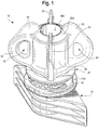
- the closure assembly 20 is provided in the form of a separate closure assembly 20 ( FIG. 1 ) which is especially suitable for being attached to a container (not illustrated), such as a flexible, collapsible pouch that would typically contain contents such as a product consisting of a fluent material.
- the pouch may be made from a material suitable for the intended application (e.g., a thin, flexible material for a pouch wherein such a material could be a polyethylene terephthalate (PET) film or a polyethylene film).
- a material suitable for the intended application e.g., a thin, flexible material for a pouch wherein such a material could be a polyethylene terephthalate (PET) film or a polyethylene film.
- PET polyethylene terephthalate
- the closure assembly manufacturer would typically make the closure assembly components by molding the components from a thermoplastic polymer and would then assemble them together in an initially assembled orientation defining a fully closed condition.
- the closure assembly manufacturer would then ship the closed closure assembly 20 to a container filler facility at another location where the container is either manufactured or otherwise provided, and where the container is filled with a product.
- the components of the closure assembly 20 could be shipped by the manufacturer in an unassembled condition to the filler facility where they could be assembled by the packager or filler before or during the process of manufacturing the completed package containing the product.
- a packager or filler may want to sterilize or otherwise clean the closure assembly components or the closed closure assembly 20 before installing the closure assembly 20 on the container.
- Some packagers or fillers typically clean or sterilize the packaging components (including a closure assembly 20) in a cleaning chamber (which may be, or may include, a sterilizing chamber) wherein a cleaning gas or sterilizing gas (e.g., hydrogen peroxide gas) flows through the chamber in contact with the packaging component or components.
- a cleaning gas or sterilizing gas e.g., hydrogen peroxide gas
- the closed closure assembly 20 of the present invention can accommodate cleaning, especially hydrogen peroxide gas sterilization, in a way that can result in enhanced cleaning or sterilization of the closed closure assembly 20.
- the closure assembly 20 ( FIG. 1 ) includes (1) a lower element 24, which may also be characterized as a receiving structure, body, base, or fitment ( FIG. 9 ), and ( 2 ) an upper element 28, which may also be characterized as a closing element, cover, cap, or overcap ( FIG. 9 ) which is adapted to be installed on, and removed from, the lower element 24.
- a lower element 24 which may also be characterized as a receiving structure, body, base, or fitment
- an upper element 28 which may also be characterized as a closing element, cover, cap, or overcap ( FIG. 9 ) which is adapted to be installed on, and removed from, the lower element 24.
- the term “fitment” will be used throughout the specification and claims to refer to the element 24, and the terms “overcap” or “cap” will be used throughout the specification and claims to refer to the element 28.
- the fitment 24 and the overcap 28 are each preferably molded from a suitable thermoplastic material such as polyethylene, polypropylene, or the like.
- a suitable thermoplastic material such as polyethylene, polypropylene, or the like.
- the fitment 24 and the overcap 28 are preferably each molded separately from high density polyethylene (HDPE). Other materials may be employed instead.
- HDPE high density polyethylene
- the fitment 24 and the overcap 28 would typically be separately molded by the manufacturer and assembled together to form the closure assembly 20 for shipment to a packager or filler at another location for installation on a container (e.g., a flexible pouch (not illustrated) - - with or without sterilization (or other cleaning) being effected prior to installation.
- a container e.g., a flexible pouch (not illustrated) - - with or without sterilization (or other cleaning) being effected prior to installation.
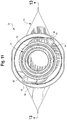
- FIG. 1 illustrates the completed closure assembly 20 with the overcap 28 installed in an initially closed condition on the fitment 24.
- FIG. 1 may be characterized as also illustrating the overcap 28 and fitment 24 in an initially assembled orientation which prevents, but can be subsequently operated to permit, communication therethrough.
- the overcap 28 is removed by the user from the fitment 28.
- the overcap 28 is unscrewed from the fitment 24 and lifted away so as to afford sufficient access to the fitment 24 (the fitment 24 being shown in FIG. 9 without the overcap 28 installed thereon).
- the user's initial or partial opening of the closure assembly 20 will permanently alter the physical condition of the overcap 28 so as to create or provide a "tamper-evident" indication to subsequent users of the initial opening or partial opening.
- the fitment 24 includes a spout 30 which defines an internal access passage 32 through the fitment 24 and which has a rim 33 ( FIG. 9 ) defining a distal open end from which a product can be discharged, or into which a product can be introduced.
- spout is used herein in the sense of a tall or a short, upwardly (i.e., axially outwardly) extending boss or other structure defining the access passage 32.
- the spout 30 also includes one cam 34 ( FIGS. 9 and 13 ) or cam follower 34, such as the illustrated helical thread 34.
- the fitment spout thread 34 could be regarded as either a cam per se or a cam follower per se for engaging a thread 70 on the overcap 28 ( FIG. 19 ) as described hereinafter. That is, if the fitment thread 34 is regarded as a cam, then the overcap thread 70 may be regarded as a cam follower. On the other hand, if the fitment thread 34 is regarded as the cam follower, then the overcap thread 70 may be regarded as the cam.
- the thread 34 and the thread 70 are each a dual lead helical thread having an identical predetermined pitch.
- the fitment 24 also includes at last one laterally projecting shear member 40.
- the shear members 40 may be located on, or as part of, the spout 30, or may be located below the spout 30.
- the structure of the spout threads 34 and shear members 40 is substantially the same as the structure of the spout threads 34 and shear members 40, respectively, as disclosed in the international patent application No. WO2015065481 .
- the receiving structure or fitment 24 may include a suitable structure for being mounted to a substance containment system (e.g., a collapsible, flexible pouch (not illustrated) or other structure of a system to which the closure assembly 20 is intended to be attached).
- a substance containment system e.g., a collapsible, flexible pouch (not illustrated) or other structure of a system to which the closure assembly 20 is intended to be attached.
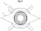
- the bottom portion of the fitment 24 typically includes a suitable conventional or special, "boat-shaped,” heat-sealable base 25 ( FIG. 9 ) the details of which form no part of the broad aspects of the present invention).
- the base 25 can be attached to the open end of a pouch with suitable, conventional heat sealing techniques.
- the base 25 has a top end surface or outer end 26 ( FIGS. 9 and 13 ) at the top of the fitment base sides which are adapted to be heat sealed to the webs of thermoplastic material defining the side walls of the pouch (not illustrated).
- closure assembly receiving structure or fitment 24 to the container (not illustrated), or to another system, are contemplated. These other means could include, for example, adhesive.
- the access passage 32 in the spout 30 of the fitment 24 can be seen in FIG. 13 .
- the access passage 32 extends from the distal, outer end rim 33 of the spout 30 and through the rest of the fitment 24.
- the access passage 32 communicates with an opening of the pouch or bottle (not illustrated) or other system, and the passage 32 permits material (gases, fluids, solids, etc.) to pass between the exterior and the interior of the system. It is to be understood that the access passage 32 need not be circular as shown.
- the access passage 32 may be elliptical, polygonal, or some other regular or irregular shape.
- the spout 30 defines an exterior sealing surface in the form of an exterior shoulder 45 having a radially outwardly facing, cylindrical first portion sealing surface 45A and an upwardly facing, annular second portion sealing surface 45B.
- the spout 30 has an interior annular projection 47 that, in the particular illustrated embodiment, is located axially below the exterior shoulder 45, and that extends laterally inwardly into the access passage 32 to define an easily sealable, interior sealing surface 47A, which, in the presently preferred form illustrated, is generally cylindrical and faces radially inwardly.
- the distance D1 from the bottom of the interior sealing surface 47A to the top end surface 26 of the fitment base 25 is 5.46 mm
- the distance D2 defined between the top of the spout 30 and the top of the base 25 is 20.83 mm.
- D1 is less than half the distance D2.
- each shear member 40 has a leading edge 42 and a trailing edge 44.
- Each shear member 40 may alternatively be described as a shear fin.
- each shear fin or shear member 40 is relatively smooth to accommodate intentional or accidental contact of the shear member 40 by a user's finger and/or lip.
- the overcap 28 is adapted to be installed on the fitment 24 in an initially assembled orientation defining an initially fully closed condition. In this condition, a combination of the overcap 28 and fitment 24 together define an initially assembled orientation which prevents, but can be subsequently operated to permit, communication through the fitment.
- the operation to permit communication through the fitment 24 is the unscrewing of the overcap 28 from the fitment 24 as described hereinafter.
- the overcap 28 has a skirt 50 ( FIG. 9 ) for engaging at least a portion of the fitment spout 30 as can be seen in FIG. 7 .
- the upper end of the overcap skirt 50 terminates in a peripheral, annular end portion 56 around a recess 56A.
- the skirt 50 is defined by a generally cylindrical sleeve having a larger diameter, lower end portion 50A.
- the overcap skirt 50 and its lower end portion 50A define an open end (not numbered) into which the fitment spout 30 extends to accommodate relative rotation between the overcap 28 and the fitment 24.
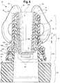
- an internal clean out plug or seal plug 58 which has a frustoconical, exterior sealing surface 58A to sealingly engage the interior scaling surface 47A on the inside of the fitment spout 30 to establish a first seal when the overcap 28 and fitment 24 are in the initially assembled closed condition.
- the overcap plug 58 is closed at its bottom end by an end wall 59 ( FIG. 6 ) which defines the bottom of the overcap recess 56A and which also defines on its periphery a frustoconical surface or chamfer 60 for accommodating insertion of the lower end of the plug 58 into, and against, the fitment spout seal surface 47A ( FIG. 6 ) on the fitment spout projection 47.
- the design can also incorporate some flexibility in the spout annular projection 47 to accommodate insertion of the overcap plug 58.
- the overcap 28 has an annular space or channel 61 ( FIG. 19 ) defined between the plug 58 and the skirt 50 for accommodating the fitment spout 30 as can be seen in FIG. 6 .
- the skirt 50 of the overcap 28 has a compound sealing surface in the form of cylindrical first portion sealing surface 63A and an annular second portion sealing surface 638 for sealingly engaging the fitment spout shoulder seal cylindrical first portion sealing surface 45A and annular second portion sealing surface 45B, respectively, when the overcap 28 and fitment 24 are in the initially assembled orientation ( FIG. 6 ).
- the novel engagement of the sealing configuration as defined by the overcap 28 and fitment 24 provides certain advantages.
- the outer seal established by the overcap surfaces 63A, 63B with the fitment spout exterior shoulder sealing surfaces 45A, 45B can prevent, or at least inhibit, ingress of contaminants upwardly past the seal into the long thread region of the spout 30 prior to (and after) installation of the closure assembly 20 on a pouch or other system.
- the low location of the inner seal established by the engaged interior spout sealing surface 47A with the lower portion of the overcap plug sealing surface 58A can prevent, or at least inhibit, ingress of contaminants upwardly past the seal into the region around the inside and outside of the spout 30 prior to installation of the closure assembly 20 on a pouch or other system.
- the spout 30 may be relatively long (i.e., tall) in applications where it is desired to accommodate a person's mouth, including lips, for drinking a fluent product through the spout. Without an outer seal near the base of the spout 30 (as effected by engagement of the spout surfaces 45A and 45B with the overcap surfaces 63A and 63B, respectively), and without an inner seal near the lower end of the plug 58 (as effected by the engagement of the plug sealing surface 58A with the fitment spout sealing surface 47A), a relatively long length of the spout 30 would be susceptible to contamination prior to installation of the closure assembly 20 on a pouch or other containment system.
- the efficiency and efficacy of the cleaning (e.g., sterilization) process can be enhanced by employment of the engaged sealing surfaces 45A/63A, 45B/63B, and 47A/58A which cooperate to define a sealed off, internal region that may then not need to be sterilized (or otherwise cleaned) after delivery of the closed closure assembly 20 to the packager.
- the configuration of the long ("deep") overcap plug 58 and the engaging fitment spout interior seal surface 47A locates the inner or interior seal "low” in the spout, and that provides other advantages when the closure assembly 20 is used with containers (e.g., pouches) containing a product that could be adversely affected by the ingress of ambient atmosphere.
- containers e.g., pouches
- some types of pouches include a laminate layer of metal which has good barrier properties (e.g., low permeability) relative to ambient atmospheric gases.
- a thermoplastic closure assembly installed on such a type of pouch typically is more gas permeable than is the metal laminate pouch, and thus, such a thermoplastic closure assembly presents a lower barrier to atmospheric gases, including oxygen.
- thermoplastic closure assembly Some characteristics (e.g., color) of some products packaged in pouches can be adversely affected (e.g., change in color) by permeation of gases (e.g., oxygen) through portions of the thermoplastic closure assembly at the top of the pouch.
- gases e.g., oxygen
- the aspect of the present invention that relates to the overcap plug seal configuration which locates the overcap plug end wall 59 and the interior seal (defined by sealing surfaces 47A and 58A) near the bottom, inner end of the spout 30.
- the positions of the overcap plug end wall 59 and of the interior seal defined by the engaged seal surfaces 47A and 58A ( FIG. 6 ) at a relatively low elevation inside the spout 30 eliminate a large, internal, free volume in the spout above the product in the pouch to reduce the amount of atmospheric gases that are trapped in the spout above the product and that could adversely affect the product.
- closure assembly configuration has two seals (i.e., inner seal surfaces 47A/58A, and outer seal surfaces 45A763A, 45B/63B) to prevent gas ingress between the spout 30 and overcap 28.
- the closure assembly provides two annular wall structures (the annular wall of the skirt 50 and the annular wall of the spout 30) to impede the permeation of the ambient atmosphere oxygen or other gases.
- the lower part of the wall of the spout 30 extending vertically between the inner seal (at the engaged surfaces 47A and 58A) and the fitment base 25 (which typically would be sealed to the low permeability metal laminate pouch) provides only a single wall thickness of thermoplastic material as a barrier in that lower region, the length of spout wall in that lower region is considerably less than what would exist if the inner seal was provided higher up, or if the inner seal was completely omitted.
- the configuration of the spout 30 and overcap plug 58 of the present invention can reduce the amount of ambient atmospheric oxygen (and other gases) passing through the closure assembly 20 to the product -- thereby reducing the possibility of adverse effects on the product or reducing such adverse effects, per se.
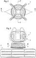
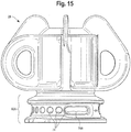
- the overcap 28 also preferably includes tabs 62 on the outside of the overcap 28, and the tabs 62 are adapted to be engaged by a user's fingers and thumb to assist in rotating the overcap 28 relative to the fitment 24.
- each tab 62 defines an aperture 64 which minimizes the amount of material required for forming each tab 62 and which may provide an additional gripping feature to permit the user's fingers and/or thumb to better engage one or more of the tabs 62.
- an inside portion of the overcap skirt 50 defines the cam 70 or a cam follower 70 which, in the illustrated preferred embodiment, is the previously identified helical thread 70 for engaging the helical thread 34 on the fitment spout 30.
- the thread 70 could be regarded either as a cam, per se, or a cam follower, per se , for engaging the fitment thread 34. That is, if overcap thread 70 is regarded as the cam, then fitment thread 34 would be regarded as the cam follower. On the other hand, if the overcap thread 70 is regarded as the cam follower, then the fitment thread 34 would be regarded as the cam.
- the relative rotational movement between the overcap 28 and the fitment 24 could result from rotating the overcap 28 relative to the fitment 24 being held stationary, or could result from rotating the fitment 24 (and attached system (e.g., pouch or a bottle)) relative to the overcap 28 being held stationary, or could result from rotating both the overcap 28 and fitment24 (and attached system) simultaneously in opposite directions.
- each thread 34 and 70 is a dual lead helical thread having a predetermined pitch.
- the pitch is selected to provide an initial gap G1 ( FIG. 6 ) between the threads 34 and 70 when the overcap 28 and fitment 24 are in the initially assembled orientation ( FIGS. 6 and 7 ).
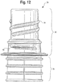
- the overcap thread 70 is defined in an upper portion of the skirt 50. Between the thread 70 and the open bottom end of the skirt 50, the skirt 50 has a lower, larger diameter, portion 50A that has a tamper-evident function and that defines two apertures 74 ( FIGS. 16 and 20 ) each extending in an arc around part of the skirt 50.
- the two apertures 74 are each divided into smaller holes or openings by one or more frangible bridges 78.
- a plurality of frangible bridges 78 extend across each aperture 74 to divide each aperture 74 into a plurality of smaller holes or openings that are each separated from an adjacent smaller hole or opening by one of seven frangible bridges 78.
- the skirt lower portion 50A of the overcap 28 defines two such elongate apertures 74A located 180° apart.
- Each such elongate aperture 74A is associated with the seven smaller circular holes which, together with the elongated opening 74A, comprise the one large aperture 74 divided by the seven frangible bridges 78.
- Each bridge 78 that is defined between two of the smaller adjacent holes has concave sides which define a bridge structure with a narrow middle portion between wider top and bottom end portions.
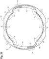
- each bridge 78 has a flat, or very slightly curving, interior surface, but each bridge 78 has an exterior surface which, as viewed in transverse cross section in FIG. 20 , defines a radially outwardly bulging configuration which can be impinged by, and cause a desirable turbulence in, a gas flow, such as during sterilization of the closure assembly 20 by a packager prior to installation of the closure assembly 20 on a container (not illustrated). This can enhance the efficiency of the sterilization process.
- each bridge 78 also minimizes the effect of restricted flow of molten plastic resin during molding of the overcap 28, and that accommodates a better filling pattern of the molten plastic resin flow during molding so as to provide a better mold fill with a reduced likelihood of creating undesirable voids or cavities. This provides a wider processing window with respect to the injection molding machine.
- the shape of the frangible bridge 78 is not difficult to mold, and provides a greater strength even though the bridge 78 is relatively thin at the narrowest point. This allows the designer to maximize the vertical height of the bridge 78.
- the opposite sides of the bridge 78 define the tapering shape leading to the narrow part of the bridge 78, and that shape accommodates a thicker, stronger shear member 40 in an adjacent portion of the aperture 74 when the overcap 28 is rotated relative to the fitment 24 as is described in detail hereinafter.
- the number of frangible bridges 78 extending across the aperture 74 to define the smaller holes may be fewer than seven or may be more than seven.
- most of the frangible bridges 78 have oppositely facing sides that each has a concave configuration that defines the above-described tapering shape which provides the above-described advantages.
- each tether web 94 defines an internal recess 96.
- Each recess 96 is radially inwardly open, and each recess 96 extends axially so that is axially open at the bottom open end of the skirt 50.
- the fitment 24 has two oppositely facing, 180° spaced-apart shear members 40
- the overcap skirt 50 has two sets of multiple-bridged apertures 74 divided by the frangible bridges 78 into smaller openings, and each of the two sets of apertures 74 and frangible bridges 78 is designed to interact with an associated one of the two shear members 40 as explained hereinafter.
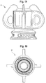
- the lower edge of the skirt 50 has a generally circular flange 100 having two oppositely facing planar surfaces 102 which are 180° apart. These may be used as keys or guides by the manufacturer to establish a desired orientation during conveyance and assembly of overcap 28 with the fitment 24.
- the fitment 24 and the closure overcap 28 are preferably separately molded or otherwise provided as separate components.
- the manufacturer assembles the two components together by effecting relative axial movement between the two components so as to force the spout 30 of the fitment 24 into the skirt 50 of the overcap 28.
- At least a portion of at least one of the components is sufficiently flexible and resilient to accommodate the insertion of the fitment spout 30 into the open end of the overcap skirt 50 in the initially assembled orientation (see FIGS. 1 , 6 , 7 , and 8 ).
- each shear member 40 is located so that it is received in, and projects through, the elongate opening portion 74A of one of the apertures 74.
- the assembly process is preferably effected without relative rotation between the overcap 28 and fitment 24. However, in an alternate assembly process, the two components could be threaded together and screwed into the initially assembled orientation.
- the projecting shear members 40 in conjunction with the apertures 74 and 74A, can cause more desirable turbulence in a gas flow, such as during the sterilization of the closed closure assembly 20 by the packager prior to installation of the closure assembly 20 on a container (not illustrated). This can enhance the efficiency of the sterilization process.
- the fitment spout thread 34 does not initially engage the overcap skirt thread 70 in a manner that would effect axial movement of the overcap 28 during an initial amount of relative rotation between the fitment 24 and overcap 28. Rather, the fitment thread 34 and overcap thread 70 have a predetermined, identical pitch and are initially separated by a predetermined gap G1 ( FIG. 6 ) so that initial rotation of the overcap 28 in the opening direction (indicated by arrow 108 in FIG.
- the overcap 28 will initially rotate about the vertical axis, but will not initially also move axially outwardly up and along the fitment spout 30.
- the fitment thread 34 and overcap thread 70 are configured with the initial gap G1 so that they do not effect axial relative movement between the fitment 24 and overcap 28 until relative rotation has occurred over a predetermined angle of rotation (e.g., about 100°). Only after a sufficient amount of initial relative rotation do the threads 34 and 70 cooperate to cause the overcap 28 to move axially upwardly (outwardly) along the fitment spout 30.
- the amount of rotation required before the overcap 28 is axially moved relative to the fitment 24 may be designed to be greater or smaller than 100°, depending on the particular designs of the skirt apertures 74 and various other features of the closure assembly 20.
- each shear member 40 projects outwardly into, and preferably partially through, one of the associated overcap skirt apertures 74 and in particular, partially through the elongate portion 74A of the aperture 74 which is initially divided by the plurality of frangible bridges 78.
- the frangible bridges 78 sequentially move against the leading edge 42 of the associated shear member 40 and are severed by the shear member 40.
- the overcap thread 70 and the fitment thread 34 are initially not effective to cause axial movement of the overcap 28 until a predetermined amount of rotation has occurred (e.g., about 100°) as previously explained thus the overcap 28 initially only rotates, but does not initially move axially upwardly relative to the fitment 24.
- the user continues rotating the overcap 28 so that the projecting shear members 40 each sequentially sever the associated frangible bridges 78.
- each laterally projecting shear member 40 begins to engage the part of the tether web 94 between the last sheared frangible bridge 78/78A and the beginning of the elongate opening portion 74A of the other aperture 74.
- This engagement of the skirt tether webs 94 with the shear members 40 can cause the lower portion of the skirt 50 to deform radially outwardly (at least temporarily) in opposite directions (as described in the international patent application No. WO2015065481 ).
- the radial distortion and deformation of the lower portion of the skirt 50 be only elastic and temporary. In other applications, it may be desired to provide a design in which at least some amount of the radial distortion and deformation of the overcap 28 is a permanent, inelastic deformation. While the permanent radial deformation and distortion of the lower part of the skirt 50 of the overcap 28 might be desirable in some applications, and while such permanent radial distortion could provide evidence of the opening of, or at last an attempt to open, the closure 20, it may not be necessary or desired in other applications.
- each frangible bridge 78 preferably generates an audible click.
- the audible clicks may sound somewhat like the noise created when a conventional zipper is opened or closed. The user can tell from the sound that the frangible bridges 78 are being severed. Of course, the user can also visually observe the severing of the frangible bridges 78.
- each frangible bridge 78 may be more or less audible to the user. Although the generation of a sound that is particularly audible to the user may be preferred in some applications, that may not be desirable or needed in other applications.
- each frangible bridge 78 may also provide a slight tactile feedback so that a relatively rapid rotation of the overcap 28 through a first angle of rotation (e.g., 100°) can result in a generally continuous vibratory feeling or feedback that is sensed by the user who is opening the closure.
- a first angle of rotation e.g. 100°
- Such discernible tactile feedback while preferred in some applications, may not be desirable or needed in other applications.
- the overcap 28 As each shear member 40 begins to engage, and outwardly deform, the lower portion of the skirt 50 of the overcap 28, the fitment thread 34 and the overcap thread 70 begin to contact in a camming engagement that exerts an axial force on the overcap 28 tending to urge the overcap 28 axially upwardly relative to the fitment 24.
- the overcap 28 is not initially free to move upwardly relative to the fitment 24 because a portion of each shear member 40 still lies within the associated aperture 74 thereby preventing upward movement of the portion of the skirt 50 below the apertures 74.
- the overcap skirt 50 becomes subject to axial tension and begins to elongate very slightly-preferably within the elastic range of the material.
- each shear member 40 is laterally tapered so that it narrows toward its trailing end 44.
- the decreasing radial extent of each shear member 40 toward its trailing end 44 is such that, after sufficient rotation of the overcap 28 in the opening direction, each shear member 40 is no longer projecting into the overcap skirt aperture 74 and is no longer effective to positively resist the upward force being exerted by the lower portion of the skirt 50.
- the overcap skirt 50 which has been elastically stretched in the axial direction, is now able to overcome any existing frictional engagement with the shear members 40, and can spring upwardly slightly, and this causes the lower edges of the skirt apertures 74 to move upwardly past each shear member 40.
- the action of a lower portion of the skirt 50 springing upwardly relative to each shear member 40 is preferably accompanied by a physical sensation that is felt by the user when the user rotates the overcap 28 to the open condition.
- the user may sense that the overcap 28 is "jumping up” or “popping up” or “snapping up” relative to the fitment 24. This sudden movement of the overcap 28 in the upward direction is preferred so as to provide the user with a further indication of the continuation of the opening process, but such a feature is not a required or essential feature.
- each tether web 94 defining the recess 96 preferably remains outwardly distorted, but is not torn or severed.
- the lower portion of the skirt 50 below the apertures 74 remains tethered (attached) to the portion of the skirt 50 above the apertures 74 even though all of the frangible bridges 78 have been severed.
- the portion of the skirt 50 that has been radially outwardly deformed can now be pulled upwardly together with the rest of the overcap 28 by the action of the overcap thread 70 in camming engagement with the thread 34 of the fitment 24.
- the overcap 28 is moved axially (i.e., translated) further up and along the spout 30. Eventually, the threads 34 and 70 become disengaged, and the entire overcap 28 can be lifted upwardly off of the fitment 24 to open the closure assembly 20.
- each shear member 40 is adapted for guiding the overcap skirt 50 as it rides up and around the shear members 40 during the relative axially upward movement of the overcap 28 as the overcap 28 is being rotated by the user.
- each shear member 40 can function to help guide the overcap 28 over the shear members 40 when the manufacturer initially installs the overcap 28 on the fitment 24.
- the process for assembling the overcap 28 and the fitment 24 by the manufacturer could include the manufacturer merely pushing the overcap 28 down on the fitment 24 while both components are in proper rotational alignment for the initially assembled (closed) orientation ( FIGS. 1 and 9 ), and the flexibility of the components, especially the flexibility of the overcap 28, would accommodate such an installation.
- the overcap 28 could also be rotated as it is being pushed down on the fitment 24 so as to engage the fitment thread 34 with the overcap thread 70 with the rotation being terminated at the point when the azimuthal (i.e., rotational) alignment between the two components corresponds to the fully closed, initially assembled orientation,
- the overcap frangible bridges 78 are severed, and the overcap lower end may remain (and preferably remains) radially distorted, but the overcap 28 also remains a unitary structure without any separate tear-off pieces or bands being generated by the opening process.
- the structural and operational features of the preferred embodiment of the closure assembly 20 which prevent the formation of smaller, separate, discrete waste pieces are not an essential requirement of the broad aspects of the invention.
- the overcap 28 it may be desirable to design the overcap 28 so that after the overcap 28 has been opened and removed from the fitment 24, there remains some small amount of outward radial distortion or deformation along the lower edge of the skirt 50 which defines a somewhat elongate or oval shape (as viewed in plan from above or below). In other applications, it may not be desired to have a permanent deformation, and it may instead be desirable to design the overcap skirt 50 so that it generally remains with an original, undeformed attractive shape.
- the combination of the overcap 28 and fitment 24 can be designed to provide apertures and bridges to indicate that the overcap has been previously opened, or at least that an attempt was made to open the overcap -- however, such features are not essential to other broad aspects of the invention.
- closure assembly 20 of the present invention need not necessarily include all of the features that have been so far described.
- the number and shape of the frangible bridges 78, and the apertures 74, including openings defined between the frangible bridges 78 can be varied, or the tamper-evident features (e.g., bridges 78, apertures 74, and shear members 40) can be omitted altogether.
- the closure assembly 20 described herein includes the following two main concepts, concept 1 and concept 2, that are provided in combination with each other
Landscapes
- Engineering & Computer Science (AREA)
- Mechanical Engineering (AREA)
- Closures For Containers (AREA)
Claims (8)
- Combinaison composée d'un couvercle de surbouchage (28) et d'une douille (24) pour un récipient qui conjointement dans une orientation initialement assemblée, empêchent, mais peuvent être sensiblement actionnés pour permettre, la communication par le biais de la douille (24), ladite combinaison comprenant :ladite douille (24) ayant un bec verseur (30) définissant :(A) un passage d'accès (32),(B) une surface d'étanchéité intérieure (47A), et(C) une surface d'étanchéité extérieure (45A, 45B) ; ledit bec verseur (30) a une extrémité externe définissant un rebord (33) autour dudit passage d'accès (32) ; etledit couvercle de surbouchage (28) ayant :(A) un pont supérieur (56) à partir duquel s'étend un bouchon creux allongé (58), ledit bouchon creux allongé (58) ayant une surface d'étanchéité de bouchon (58A) pour mettre en prise ladite surface d'étanchéité intérieure (47A) de douille afin de créer un premier joint d'étanchéité (47A, 58A) lorsque ledit couvercle de surbouchage (28) et ladite douille (24) sont dans ladite orientation initialement assemblée,(B) une jupe (50) s'étendant sur au moins une partie dudit bec verseur (30) et ayant une surface d'étanchéité de jupe (63A, 63B) pour mettre en prise ladite surface d'étanchéité extérieure (45A, 45B) de douille afin de créer un second joint d'étanchéité (45A, 45B/63A, 63B) lorsque ledit couvercle de surbouchage (28) et ladite douille (24) sont dans ladite orientation initialement assemblée, et(C) un canal annulaire (61) défini entre ledit bouchon creux allongé (58) et ladite jupe (50) dans laquelle ledit bec verseur de douille (30) s'étend pour accepter la rotation relative entre ledit couvercle de surbouchage (28) et ladite douille (24) ; et ladite combinaison composée du couvercle de surbouchage (28) et de la douille (24) étant caractérisée en ce que :ladite douille (24) comprend en outre une base (25) qui peut être scellée sur une poche flexible et qui a une extrémité externe de base (26) à partir de laquelle ledit bec verseur (30) fait saillie ;ledit premier joint d'étanchéité (47A, 58A) est axialement espacé sur une première distance (D1) de ladite extrémité externe de base (26) ;ledit rebord (33) est axialement espacé sur une seconde distance (D2) de ladite extrémité externe de base (26) ;ladite première distance (D1) est inférieure à la moitié de ladite seconde distance (D2).
- Combinaison selon la revendication 1, dans laquelle :ledit bec verseur (30) définit l'un parmi une came (34, 70) et un poussoir de came (34, 70) ; etladite jupe (50) définit l'autre parmi ladite came (34, 70) et ledit poussoir de came (34, 70) pour mettre en prise ledit un parmi ladite came (34, 70) et le poussoir de came (34, 70) sur ledit bec verseur (30) afin d'effectuer le mouvement axial relatif entre ladite douille (24) et ledit couvercle de surbouchage (28).
- Combinaison selon la revendication 2, dans laquelle :
ladite came (34, 70) et le poussoir de came (34, 70) sont positionnés entre lesdits premier et second joints d'étanchéité. - Combinaison selon la revendication 1, dans laquelle :
ledit premier joint d'étanchéité (47A, 58A) est positionné axialement vers l'intérieur dudit second joint d'étanchéité (45A, 45B/63A, 63B). - Combinaison selon la revendication 1, dans laquelle :
ladite surface d'étanchéité de bouchon (58A) est tronconique et ladite surface d'étanchéité intérieure de douille (47A) est généralement cylindrique, moyennant quoi ledit premier joint d'étanchéité (47A, 58A) est annulaire. - Combinaison selon la revendication 1, dans laquelle :ladite surface d'étanchéité extérieure de douille (45A, 45B) a la forme d'un épaulement définissant (1) une première partie cylindrique (45A), et (2) une seconde partie annulaire (45B) ; etladite surface d'étanchéité de jupe (63A, 63B) a (1) une première partie cylindrique (63A) pour mettre en prise ladite première partie cylindrique (45A) de surface d'étanchéité extérieure de douille, et (2) une seconde partie annulaire (63B) pour mettre en prise ladite seconde partie annulaire (45B) de surface d'étanchéité extérieure de douille.
- Combinaison selon la revendication 1, dans laquelle :
ladite surface d'étanchéité intérieure de bec verseur (47A) est définie par une saillie annulaire (47) s'étendant latéralement vers l'intérieur dans ledit passage d'accès (32). - Combinaison selon la revendication 1, dans laquelle :
ledit bec verseur (30) a une extrémité externe définissant un rebord (33) qui est axialement espacé à partir dudit pont supérieur de couvercle de surbouchage (56) lorsque ledit couvercle de surbouchage (28) et ladite douille (24) sont dans ladite orientation initialement assemblée.
Applications Claiming Priority (1)
| Application Number | Priority Date | Filing Date | Title |
|---|---|---|---|
| PCT/US2015/018864 WO2016140668A1 (fr) | 2015-03-05 | 2015-03-05 | Douille et couvercle de surbouchage pour celle-ci |
Publications (3)
| Publication Number | Publication Date |
|---|---|
| EP3265396A1 EP3265396A1 (fr) | 2018-01-10 |
| EP3265396A4 EP3265396A4 (fr) | 2018-11-07 |
| EP3265396B1 true EP3265396B1 (fr) | 2020-05-06 |
Family
ID=56848315
Family Applications (1)
| Application Number | Title | Priority Date | Filing Date |
|---|---|---|---|
| EP15884132.0A Active EP3265396B1 (fr) | 2015-03-05 | 2015-03-05 | Douille et couvercle de surbouchage pour celle-ci |
Country Status (8)
| Country | Link |
|---|---|
| US (2) | US9611079B2 (fr) |
| EP (1) | EP3265396B1 (fr) |
| CN (1) | CN107207134B (fr) |
| BR (1) | BR112017014444A2 (fr) |
| CO (1) | CO2017009036A2 (fr) |
| ES (1) | ES2795777T3 (fr) |
| MX (1) | MX2017010168A (fr) |
| WO (1) | WO2016140668A1 (fr) |
Families Citing this family (27)
| Publication number | Priority date | Publication date | Assignee | Title |
|---|---|---|---|---|
| DE102014016178A1 (de) * | 2014-11-03 | 2016-05-04 | Georg Menshen Gmbh & Co. Kg | Ausgießer eines Behälters |
| US20170073126A1 (en) * | 2016-08-13 | 2017-03-16 | Anders Brockett Comer | Ergonomic grip lid |
| WO2018136068A1 (fr) * | 2017-01-19 | 2018-07-26 | Silgan White Cap LLC | Partie de montage destinée à un bec verseur |
| NL2018749B1 (en) * | 2017-04-20 | 2018-11-05 | Scholle Ipn Ip Bv | A closure assembly |
| DK179644B8 (en) * | 2017-07-14 | 2019-04-10 | Nørkjær Karsten | Bottle cap |
| WO2019021069A1 (fr) * | 2017-07-26 | 2019-01-31 | Guala Dispensing S.P.A. | Système de connexion entre une bouteille et une tête de distribution |
| US11338309B2 (en) | 2017-07-26 | 2022-05-24 | Guala Dispensing S.P.A | Connection system between a bottle and a dispensing head |
| USD870277S1 (en) * | 2017-07-28 | 2019-12-17 | Technoflex | Connector |
| USD835780S1 (en) * | 2017-10-24 | 2018-12-11 | Genicon, Inc. | Retrieval bag collar |
| EP3704031A1 (fr) * | 2017-11-01 | 2020-09-09 | Scholle IPN IP B.V. | Bouchon de fermeture pour poche |
| US10654628B2 (en) | 2017-11-01 | 2020-05-19 | Scholle Ipn Ip Bv | Cap for a pouch |
| IT201900002103A1 (it) * | 2019-02-13 | 2020-08-13 | Guala Pack Spa | Tappo per cannuccia per un imballo flessibile a pareti sottili |
| USD910170S1 (en) * | 2019-04-19 | 2021-02-09 | Hollister Incorporated | Ostomy pouch outlet |
| USD905852S1 (en) * | 2019-07-23 | 2020-12-22 | Hollister Incorporated | Drainage bag outlet including closure |
| USD984262S1 (en) | 2020-07-22 | 2023-04-25 | Georg Menshen Gmbh & Co. Kg | Seal cap |
| DE102020119965A1 (de) * | 2020-07-29 | 2022-02-03 | Georg Menshen Gmbh & Co. Kg | Verschlusskappe mit Flügeln |
| USD992417S1 (en) | 2020-07-31 | 2023-07-18 | Georg Menshen Gmbh & Co. Kg | Sealing cap |
| USD962764S1 (en) | 2020-10-29 | 2022-09-06 | Cheer Pack North America | Cap for a pouch |
| USD962766S1 (en) | 2020-10-29 | 2022-09-06 | Cheer Pack North America | Cap for a pouch |
| USD966890S1 (en) | 2020-10-29 | 2022-10-18 | Cheer Pack North America | Cap for a pouch |
| USD971730S1 (en) | 2020-10-29 | 2022-12-06 | Cheer Pack North America | Cap for a pouch |
| USD971728S1 (en) | 2020-10-29 | 2022-12-06 | Cheer Pack North America | Cap for a pouch |
| US11414244B2 (en) * | 2020-10-29 | 2022-08-16 | Cheer Pack North America | System and method for connecting members |
| USD962765S1 (en) | 2020-10-29 | 2022-09-06 | Cheer Pack North America | Cap for a pouch |
| IT202200002978A1 (it) * | 2022-02-17 | 2023-08-17 | Guala Pack Spa | Chiusura per una cannuccia di un imballo a pareti sottili |
| JP1750516S (ja) * | 2022-04-12 | 2023-08-08 | 容器用閉じ具 | |
| USD1023752S1 (en) * | 2022-08-30 | 2024-04-23 | Guala Pack S.P.A. | Closure for containers |
Citations (7)
| Publication number | Priority date | Publication date | Assignee | Title |
|---|---|---|---|---|
| JP2002104447A (ja) | 2000-09-22 | 2002-04-10 | Daiwa Can Co Ltd | 袋状容器の蓋付き注出口 |
| JP2004090964A (ja) | 2002-08-30 | 2004-03-25 | Shirouma Science Co Ltd | バリヤキャップ装置 |
| JP2004131157A (ja) | 2002-10-15 | 2004-04-30 | Nippon Kimu Kk | 口栓、及び口栓付き収容体 |
| US7077278B2 (en) | 2001-06-18 | 2006-07-18 | Bericap Holding Gmbh | Screw cap comprising a tamper-evident band |
| EP1940699B1 (fr) | 2005-10-17 | 2011-03-16 | The Patent Company | Ensemble de bouchage pour emballage et procede d'obturation d'emballage |
| FR2921346B1 (fr) | 2007-09-25 | 2012-09-28 | Oreal | Systeme de bouchage a double etancheite |
| WO2013147599A1 (fr) | 2012-03-29 | 2013-10-03 | Ipn Ip B.V. | Ensembles de fermeture de contenant |
Family Cites Families (78)
| Publication number | Priority date | Publication date | Assignee | Title |
|---|---|---|---|---|
| US1898342A (en) | 1929-07-22 | 1933-02-21 | W A Sheaffer Pen Co | Container |
| US2374143A (en) | 1942-11-14 | 1945-04-17 | Charlotte V Stevenson | Combined bottle cap and stopper |
| US2582721A (en) | 1949-04-26 | 1952-01-15 | Dick Co Ab | Bottle closure |
| GB696662A (en) * | 1951-05-31 | 1953-09-02 | Coty Inc | Improvements in bottle capping means |
| CH397456A (de) * | 1960-11-11 | 1965-08-15 | Golde Erich | Schraubverschluss mit Sicherung an einem Gefäss |
| US3581927A (en) | 1968-09-23 | 1971-06-01 | Weck & Co Inc Edward | Container closure |
| US3540612A (en) | 1969-02-17 | 1970-11-17 | Bio Dynamics Inc | Bottle cap and bottle combination |
| CA1038806A (fr) | 1974-11-05 | 1978-09-19 | Dietmar Aichinger | Capuchon vissant pour contenants |
| US4057160A (en) | 1976-02-02 | 1977-11-08 | E. & J. Gallo Winery | Self-retaining bottle stopper |
| FR2391926A2 (fr) | 1976-02-03 | 1978-12-22 | Grussen Jean | Capsule de bouchage a vis a etancheite amelioree et moule de fabrication |
| US4206852A (en) | 1979-01-26 | 1980-06-10 | Aluminum Company Of America | Linerless closure for pressurized container |
| US4299330A (en) * | 1979-10-03 | 1981-11-10 | The Continental Group, Inc. | Container closure device |
| EP0076778A1 (fr) | 1981-10-05 | 1983-04-13 | Crown Obrist AG | Bouchon de fermeture en matière plastique |
| EP0093690A1 (fr) | 1982-05-04 | 1983-11-09 | Crown Obrist AG | Fermeture pour récipient |
| US4583652A (en) | 1984-07-10 | 1986-04-22 | Goldberg James R | Safety closure device |
| GB2172273B (en) * | 1985-03-14 | 1988-12-21 | Bormioli Metalplast Spa | Plastic cap in two parts incorporating a breakable seal, for bottles in particular |
| US4609115A (en) | 1985-05-15 | 1986-09-02 | Phoenix Closures, Inc. | Tamper-evident closure and bottle assembly |
| US4896783A (en) * | 1985-09-27 | 1990-01-30 | Manufacturers Hanover Trust Company | Container and cap assembly |
| NL8600859A (nl) * | 1986-04-03 | 1987-11-02 | Kornelis Kunsthars Prod Ind Bv | Schroefsluiting, alsmede de daarvoor bestemde schroefdop en houder. |
| US4712699A (en) | 1986-10-02 | 1987-12-15 | Captive Plastics, Inc. | Package employing unique seal |
| FR2650253B1 (fr) | 1989-07-28 | 1991-10-04 | Cebal | Ensemble d'une capsule a ouverture et d'un recipient a goulot en matiere plastique, et son utilisation |
| SE468206B (sv) | 1989-10-04 | 1992-11-23 | Cerbo Ab | Skruvlocksfoerslutning, innefattande ett invaendigt gaengat skruvlock och ett separat, utvaendigtgaengat lockfaeste |
| US5009323A (en) | 1989-11-13 | 1991-04-23 | Sunbeam Plastics Corporation | Tamper indicating closure having a rotary seal |
| US4946055A (en) | 1990-01-09 | 1990-08-07 | Towns Edward J | Tamper indicating screw cap |
| CA2062008A1 (fr) * | 1991-03-05 | 1992-09-06 | Portola Packaging, Inc. | Bouchon muni d'une cloison de bec verseur |
| US5456375A (en) | 1992-05-20 | 1995-10-10 | Specialised Purchasing Concepts Unit Trust | Tamper evident cap and container |
| WO1994011267A2 (fr) | 1992-11-13 | 1994-05-26 | Beeson And Sons Limited | Ameliorations apportees a une bague indicatrice d'effraction pour la fermeture d'un recipient |
| US5527513A (en) * | 1994-04-08 | 1996-06-18 | Becton Dickinson And Company | Collection assembly |
| US5458113A (en) | 1994-08-12 | 1995-10-17 | Becton Dickinson And Company | Collection assembly |
| PL322006A1 (en) | 1995-02-21 | 1998-01-05 | Metal Closures Group Ltd | Self-centering container closure |
| US6041953A (en) | 1995-04-05 | 2000-03-28 | Goodall; Donald Terry | Containers and closures therefor |
| GB9520720D0 (en) * | 1995-10-10 | 1995-12-13 | Prelude Uk Ltd | Containers |
| US5692628A (en) | 1996-01-11 | 1997-12-02 | Rexam Closure, Inc. | Press-on screw-off self-tapping closure/container package |
| US5630522A (en) | 1996-02-09 | 1997-05-20 | Rexam Closures, Inc. | Dual contact plug seal for threaded closure |
| US5699924A (en) * | 1996-04-26 | 1997-12-23 | Portola Packaging, Inc. | Attachment of tamper-evidencing band to closure skirt |
| US6145688A (en) * | 1996-07-17 | 2000-11-14 | Smith; James C. | Closure device for containers |
| US5954215A (en) | 1996-12-11 | 1999-09-21 | James A. Schwartz | Leak-proof container |
| EP1027261B1 (fr) | 1997-10-30 | 2004-03-17 | International Plastics and Equipment Corporation | Fermeture encliquetable s'arrachant par devissage |
| US6338414B1 (en) | 1998-03-03 | 2002-01-15 | International Packaging Engineering | Plastic closing cap with a separable safety seal and inner seal |
| US6105802A (en) | 1998-06-22 | 2000-08-22 | Clayton Corporation | Push-on closure container assembly |
| US6044995A (en) | 1998-09-22 | 2000-04-04 | Taiwan Hon Chuan Enterprise Co., Ltd. | Negative-pressure-resistible leakage-proof bottle cover |
| IT1310921B1 (it) * | 1999-06-24 | 2002-02-27 | Mrp Medical Res & Promotion Es | Flacone pluridose con beccuccio di dosaggio per liquidi,particolarmente prodotti farmaceutici. |
| AU760512B2 (en) | 1999-10-26 | 2003-05-15 | Pathtainer Systems International Pty Limited | Container and lid combination with tamper evident mechanism |
| KR20010096600A (ko) | 2000-03-13 | 2001-11-07 | 도케 케이시 | 합성수지제 용기뚜껑 |
| PL361094A1 (en) | 2000-10-13 | 2004-09-20 | Bericap | Plastic closure cap, with sealing skirt |
| AU2001295365A1 (en) * | 2000-11-03 | 2002-05-15 | Terxo Ag | Screw cap with a guarantee strip |
| US20020130101A1 (en) | 2001-03-13 | 2002-09-19 | Len Ekkert | Dual sealing closure |
| DE10207204A1 (de) * | 2001-04-05 | 2002-12-12 | Alpla Werke | Kombination aus einer Flasche mit rastgehaltertem Adapter und/oder einer Verschlusskappe |
| US6477743B1 (en) | 2001-08-14 | 2002-11-12 | Seaquist Closures Foreign, Inc. | Twist-openable dispensing closure accommodating optional liner puncture feature |
| US6702134B2 (en) | 2001-09-28 | 2004-03-09 | Gen-Probe Incorporated | Closure system |
| US6702161B2 (en) | 2001-12-12 | 2004-03-09 | Portola Packaging, Inc. | Closure having rotatable spout and axially movable stem |
| NL1019903C2 (nl) * | 2002-02-05 | 2003-08-07 | Itsac Nv | Op een hals van een houder schroefbare kraag. |
| AUPS053202A0 (en) | 2002-02-15 | 2002-03-07 | Zork Pty Ltd | Closure |
| JP2003261155A (ja) | 2002-03-04 | 2003-09-16 | Alcoa Closure Systems Japan Ltd | 合成樹脂製キャップ |
| US7249694B2 (en) * | 2002-07-26 | 2007-07-31 | Masatoshi Masuda | Valve mechanism for tube-type fluid container |
| AU2003276062B2 (en) | 2002-10-21 | 2007-02-08 | Unilever Plc | Container with snap-on closure |
| EP1585680A4 (fr) | 2002-11-20 | 2006-05-24 | Jung-Min Lee | Ensemble d'ecoulement pour recipient a liquide |
| EP1650135A1 (fr) * | 2003-07-22 | 2006-04-26 | Barangüa, S.L. | Capsule a vis pour recipient |
| JP4391162B2 (ja) | 2003-08-26 | 2009-12-24 | 株式会社細川洋行 | 液体容器の注出装置およびバッグインボックス |
| WO2005032964A2 (fr) * | 2003-10-03 | 2005-04-14 | Bristol Myers Squibb Company | Recipient et systeme d'etancheification |
| WO2005037524A2 (fr) | 2003-10-14 | 2005-04-28 | Action Uno, S.L. | Ebauche destinee a la fabrication d'un contenant, contenant et dispositif de fermeture du contenant |
| DE102004025466B4 (de) | 2004-05-25 | 2011-07-07 | Georg Menshen GmbH & Co. KG, 57413 | Verschlusskappe |
| FR2899567B1 (fr) | 2006-04-07 | 2010-08-13 | Eaux Minerales D Evian Saeme S | Systeme de fermeture pour recipient |
| US7743952B2 (en) | 2006-10-18 | 2010-06-29 | Stull Technologies, Inc. | Double bead sealing system for container closure |
| WO2008095842A1 (fr) | 2007-02-07 | 2008-08-14 | Nestle Waters Management & Technology | Emballage léger |
| MX359080B (es) | 2008-03-05 | 2018-09-06 | Becton Dickinson Co | Tapon perforable comoldeado y metodo para hacerlo. |
| US7980403B2 (en) | 2008-04-04 | 2011-07-19 | Stokely-Van Camp, Inc. | Container closure with internal threading system |
| FR2933676B1 (fr) | 2008-07-11 | 2010-08-27 | Tetra Laval Holdings & Finance | Bouchon pour un col de recipient et machine de moulage d'une matiere plastique pour fabriquer un tel bouchon. |
| GB2467355A (en) | 2009-01-30 | 2010-08-04 | Beeson & Sons Ltd | Container closure with pressure seal |
| US8479936B2 (en) * | 2009-03-10 | 2013-07-09 | Eric William Gruenwald | Water bottle with dosage cup |
| CA2785730A1 (fr) | 2009-12-31 | 2011-07-07 | Closure Systems International, Inc. | Fermeture en matiere plastique presentant une performance amelioree |
| EP2780249B1 (fr) | 2011-09-22 | 2016-12-28 | Rundpack AG | Fermeture étanche à vis |
| NL2007572C2 (en) | 2011-10-11 | 2013-04-15 | Ipn Ip Bv | A collapsible pouch closure assembly. |
| CN104053609B (zh) | 2012-01-06 | 2016-06-01 | 国际密封系统公司 | 无衬垫盖 |
| MX2014009465A (es) | 2012-02-07 | 2015-02-10 | Plastipak Packaging Inc | Tapa de sello de recipiente y ensamble. |
| JP6235005B2 (ja) | 2012-05-31 | 2017-11-22 | クロージヤー・システムズ・インターナシヨナル・インコーポレーテツドClosure Systems International Inc. | 取付けガイド付きクロージャー |
| US10005602B2 (en) | 2013-06-07 | 2018-06-26 | Scholle Ipn Ip Bv | Collapsible pouch provided with a closure assembly |
| EP3066018B1 (fr) | 2013-11-04 | 2018-08-08 | AptarGroup, Inc. | Élément de fermeture inviolable et structure de réception |
-
2015
- 2015-03-05 CN CN201580074893.7A patent/CN107207134B/zh active Active
- 2015-03-05 BR BR112017014444A patent/BR112017014444A2/pt not_active Application Discontinuation
- 2015-03-05 ES ES15884132T patent/ES2795777T3/es active Active
- 2015-03-05 MX MX2017010168A patent/MX2017010168A/es unknown
- 2015-03-05 WO PCT/US2015/018864 patent/WO2016140668A1/fr active Application Filing
- 2015-03-05 US US14/764,089 patent/US9611079B2/en active Active
- 2015-03-05 EP EP15884132.0A patent/EP3265396B1/fr active Active
-
2017
- 2017-02-20 US US15/437,312 patent/US10293988B2/en active Active
- 2017-09-04 CO CONC2017/0009036A patent/CO2017009036A2/es unknown
Patent Citations (8)
| Publication number | Priority date | Publication date | Assignee | Title |
|---|---|---|---|---|
| JP2002104447A (ja) | 2000-09-22 | 2002-04-10 | Daiwa Can Co Ltd | 袋状容器の蓋付き注出口 |
| US7077278B2 (en) | 2001-06-18 | 2006-07-18 | Bericap Holding Gmbh | Screw cap comprising a tamper-evident band |
| JP2004090964A (ja) | 2002-08-30 | 2004-03-25 | Shirouma Science Co Ltd | バリヤキャップ装置 |
| JP2004131157A (ja) | 2002-10-15 | 2004-04-30 | Nippon Kimu Kk | 口栓、及び口栓付き収容体 |
| EP1940699B1 (fr) | 2005-10-17 | 2011-03-16 | The Patent Company | Ensemble de bouchage pour emballage et procede d'obturation d'emballage |
| EP1940700B1 (fr) | 2005-10-17 | 2011-07-13 | The Patent Company | Ensemble de bouchage pour emballage |
| FR2921346B1 (fr) | 2007-09-25 | 2012-09-28 | Oreal | Systeme de bouchage a double etancheite |
| WO2013147599A1 (fr) | 2012-03-29 | 2013-10-03 | Ipn Ip B.V. | Ensembles de fermeture de contenant |
Also Published As
| Publication number | Publication date |
|---|---|
| US10293988B2 (en) | 2019-05-21 |
| EP3265396A4 (fr) | 2018-11-07 |
| US20160272380A1 (en) | 2016-09-22 |
| CN107207134B (zh) | 2020-08-04 |
| EP3265396A1 (fr) | 2018-01-10 |
| MX2017010168A (es) | 2017-11-09 |
| US9611079B2 (en) | 2017-04-04 |
| CO2017009036A2 (es) | 2017-09-11 |
| BR112017014444A2 (pt) | 2018-01-16 |
| US20170158382A1 (en) | 2017-06-08 |
| ES2795777T3 (es) | 2020-11-24 |
| CN107207134A (zh) | 2017-09-26 |
| WO2016140668A1 (fr) | 2016-09-09 |
Similar Documents
| Publication | Publication Date | Title |
|---|---|---|
| US10293988B2 (en) | Fitment and overcap therefor | |
| US10562679B2 (en) | Tamper-evident closing element and receiving structure | |
| US10501249B2 (en) | Fitment for a flexible container | |
| EP1833732A1 (fr) | Fermeture inviolable et bourrelet de col de conteneur | |
| US10173816B2 (en) | Closure with a removable membrane having an improved separability configuration | |
| US20230406577A1 (en) | Closure for a container and components for a closure | |
| EP3003894B1 (fr) | Fermeture avec couvercle et membrane amovible | |
| US7810681B2 (en) | Internal container bore mount fitment | |
| US20100140268A1 (en) | Dispensing closure with removable membrane | |
| US8631977B2 (en) | Closure for a container | |
| JP7386709B2 (ja) | 食品パッケージ用のスパウト | |
| JP7273515B2 (ja) | リング付きキャップを有する容器 | |
| WO2023014627A1 (fr) | Bouchon distributeur | |
| JP2002154563A (ja) | キャップと注出口の組合体 |
Legal Events
| Date | Code | Title | Description |
|---|---|---|---|
| STAA | Information on the status of an ep patent application or granted ep patent |
Free format text: STATUS: THE INTERNATIONAL PUBLICATION HAS BEEN MADE |
|
| PUAI | Public reference made under article 153(3) epc to a published international application that has entered the european phase |
Free format text: ORIGINAL CODE: 0009012 |
|
| STAA | Information on the status of an ep patent application or granted ep patent |
Free format text: STATUS: REQUEST FOR EXAMINATION WAS MADE |
|
| 17P | Request for examination filed |
Effective date: 20170908 |
|
| AK | Designated contracting states |
Kind code of ref document: A1 Designated state(s): AL AT BE BG CH CY CZ DE DK EE ES FI FR GB GR HR HU IE IS IT LI LT LU LV MC MK MT NL NO PL PT RO RS SE SI SK SM TR |
|
| AX | Request for extension of the european patent |
Extension state: BA ME |
|
| RAP1 | Party data changed (applicant data changed or rights of an application transferred) |
Owner name: APTARGROUP, INC. |
|
| RIC1 | Information provided on ipc code assigned before grant |
Ipc: B65D 75/58 20060101AFI20180430BHEP Ipc: B65D 41/34 20060101ALI20180430BHEP |
|
| DAV | Request for validation of the european patent (deleted) | ||
| DAX | Request for extension of the european patent (deleted) | ||
| REG | Reference to a national code |
Ref country code: DE Ref legal event code: R079 Ref document number: 602015052575 Country of ref document: DE Free format text: PREVIOUS MAIN CLASS: B65D0047200000 Ipc: B65D0075580000 |
|
| A4 | Supplementary search report drawn up and despatched |
Effective date: 20181009 |
|
| RIC1 | Information provided on ipc code assigned before grant |
Ipc: B65D 75/58 20060101AFI20181003BHEP Ipc: B65D 41/04 20060101ALI20181003BHEP Ipc: B65D 41/34 20060101ALI20181003BHEP |
|
| GRAP | Despatch of communication of intention to grant a patent |
Free format text: ORIGINAL CODE: EPIDOSNIGR1 |
|
| STAA | Information on the status of an ep patent application or granted ep patent |
Free format text: STATUS: GRANT OF PATENT IS INTENDED |
|
| INTG | Intention to grant announced |
Effective date: 20191014 |
|
| GRAS | Grant fee paid |
Free format text: ORIGINAL CODE: EPIDOSNIGR3 |
|
| GRAA | (expected) grant |
Free format text: ORIGINAL CODE: 0009210 |
|
| STAA | Information on the status of an ep patent application or granted ep patent |
Free format text: STATUS: THE PATENT HAS BEEN GRANTED |
|
| AK | Designated contracting states |
Kind code of ref document: B1 Designated state(s): AL AT BE BG CH CY CZ DE DK EE ES FI FR GB GR HR HU IE IS IT LI LT LU LV MC MK MT NL NO PL PT RO RS SE SI SK SM TR |
|
| REG | Reference to a national code |
Ref country code: GB Ref legal event code: FG4D |
|
| REG | Reference to a national code |
Ref country code: CH Ref legal event code: EP Ref country code: AT Ref legal event code: REF Ref document number: 1266397 Country of ref document: AT Kind code of ref document: T Effective date: 20200515 |
|
| REG | Reference to a national code |
Ref country code: IE Ref legal event code: FG4D |
|
| REG | Reference to a national code |
Ref country code: DE Ref legal event code: R096 Ref document number: 602015052575 Country of ref document: DE |
|
| REG | Reference to a national code |
Ref country code: LT Ref legal event code: MG4D |
|
| REG | Reference to a national code |
Ref country code: NL Ref legal event code: MP Effective date: 20200506 |
|
| PG25 | Lapsed in a contracting state [announced via postgrant information from national office to epo] |
Ref country code: FI Free format text: LAPSE BECAUSE OF FAILURE TO SUBMIT A TRANSLATION OF THE DESCRIPTION OR TO PAY THE FEE WITHIN THE PRESCRIBED TIME-LIMIT Effective date: 20200506 Ref country code: PT Free format text: LAPSE BECAUSE OF FAILURE TO SUBMIT A TRANSLATION OF THE DESCRIPTION OR TO PAY THE FEE WITHIN THE PRESCRIBED TIME-LIMIT Effective date: 20200907 Ref country code: LT Free format text: LAPSE BECAUSE OF FAILURE TO SUBMIT A TRANSLATION OF THE DESCRIPTION OR TO PAY THE FEE WITHIN THE PRESCRIBED TIME-LIMIT Effective date: 20200506 Ref country code: IS Free format text: LAPSE BECAUSE OF FAILURE TO SUBMIT A TRANSLATION OF THE DESCRIPTION OR TO PAY THE FEE WITHIN THE PRESCRIBED TIME-LIMIT Effective date: 20200906 Ref country code: SE Free format text: LAPSE BECAUSE OF FAILURE TO SUBMIT A TRANSLATION OF THE DESCRIPTION OR TO PAY THE FEE WITHIN THE PRESCRIBED TIME-LIMIT Effective date: 20200506 Ref country code: GR Free format text: LAPSE BECAUSE OF FAILURE TO SUBMIT A TRANSLATION OF THE DESCRIPTION OR TO PAY THE FEE WITHIN THE PRESCRIBED TIME-LIMIT Effective date: 20200807 Ref country code: NO Free format text: LAPSE BECAUSE OF FAILURE TO SUBMIT A TRANSLATION OF THE DESCRIPTION OR TO PAY THE FEE WITHIN THE PRESCRIBED TIME-LIMIT Effective date: 20200806 |
|
| REG | Reference to a national code |
Ref country code: ES Ref legal event code: FG2A Ref document number: 2795777 Country of ref document: ES Kind code of ref document: T3 Effective date: 20201124 |
|
| PG25 | Lapsed in a contracting state [announced via postgrant information from national office to epo] |
Ref country code: BG Free format text: LAPSE BECAUSE OF FAILURE TO SUBMIT A TRANSLATION OF THE DESCRIPTION OR TO PAY THE FEE WITHIN THE PRESCRIBED TIME-LIMIT Effective date: 20200806 Ref country code: RS Free format text: LAPSE BECAUSE OF FAILURE TO SUBMIT A TRANSLATION OF THE DESCRIPTION OR TO PAY THE FEE WITHIN THE PRESCRIBED TIME-LIMIT Effective date: 20200506 Ref country code: HR Free format text: LAPSE BECAUSE OF FAILURE TO SUBMIT A TRANSLATION OF THE DESCRIPTION OR TO PAY THE FEE WITHIN THE PRESCRIBED TIME-LIMIT Effective date: 20200506 Ref country code: LV Free format text: LAPSE BECAUSE OF FAILURE TO SUBMIT A TRANSLATION OF THE DESCRIPTION OR TO PAY THE FEE WITHIN THE PRESCRIBED TIME-LIMIT Effective date: 20200506 |
|
| REG | Reference to a national code |
Ref country code: AT Ref legal event code: MK05 Ref document number: 1266397 Country of ref document: AT Kind code of ref document: T Effective date: 20200506 |
|
| PG25 | Lapsed in a contracting state [announced via postgrant information from national office to epo] |
Ref country code: AL Free format text: LAPSE BECAUSE OF FAILURE TO SUBMIT A TRANSLATION OF THE DESCRIPTION OR TO PAY THE FEE WITHIN THE PRESCRIBED TIME-LIMIT Effective date: 20200506 Ref country code: NL Free format text: LAPSE BECAUSE OF FAILURE TO SUBMIT A TRANSLATION OF THE DESCRIPTION OR TO PAY THE FEE WITHIN THE PRESCRIBED TIME-LIMIT Effective date: 20200506 |
|
| PG25 | Lapsed in a contracting state [announced via postgrant information from national office to epo] |
Ref country code: AT Free format text: LAPSE BECAUSE OF FAILURE TO SUBMIT A TRANSLATION OF THE DESCRIPTION OR TO PAY THE FEE WITHIN THE PRESCRIBED TIME-LIMIT Effective date: 20200506 Ref country code: DK Free format text: LAPSE BECAUSE OF FAILURE TO SUBMIT A TRANSLATION OF THE DESCRIPTION OR TO PAY THE FEE WITHIN THE PRESCRIBED TIME-LIMIT Effective date: 20200506 Ref country code: EE Free format text: LAPSE BECAUSE OF FAILURE TO SUBMIT A TRANSLATION OF THE DESCRIPTION OR TO PAY THE FEE WITHIN THE PRESCRIBED TIME-LIMIT Effective date: 20200506 Ref country code: CZ Free format text: LAPSE BECAUSE OF FAILURE TO SUBMIT A TRANSLATION OF THE DESCRIPTION OR TO PAY THE FEE WITHIN THE PRESCRIBED TIME-LIMIT Effective date: 20200506 Ref country code: RO Free format text: LAPSE BECAUSE OF FAILURE TO SUBMIT A TRANSLATION OF THE DESCRIPTION OR TO PAY THE FEE WITHIN THE PRESCRIBED TIME-LIMIT Effective date: 20200506 Ref country code: SM Free format text: LAPSE BECAUSE OF FAILURE TO SUBMIT A TRANSLATION OF THE DESCRIPTION OR TO PAY THE FEE WITHIN THE PRESCRIBED TIME-LIMIT Effective date: 20200506 |
|
| REG | Reference to a national code |
Ref country code: DE Ref legal event code: R026 Ref document number: 602015052575 Country of ref document: DE |
|
| PLBI | Opposition filed |
Free format text: ORIGINAL CODE: 0009260 |
|
| PLAX | Notice of opposition and request to file observation + time limit sent |
Free format text: ORIGINAL CODE: EPIDOSNOBS2 |
|
| PG25 | Lapsed in a contracting state [announced via postgrant information from national office to epo] |
Ref country code: SK Free format text: LAPSE BECAUSE OF FAILURE TO SUBMIT A TRANSLATION OF THE DESCRIPTION OR TO PAY THE FEE WITHIN THE PRESCRIBED TIME-LIMIT Effective date: 20200506 Ref country code: PL Free format text: LAPSE BECAUSE OF FAILURE TO SUBMIT A TRANSLATION OF THE DESCRIPTION OR TO PAY THE FEE WITHIN THE PRESCRIBED TIME-LIMIT Effective date: 20200506 |
|
| 26 | Opposition filed |
Opponent name: KAYSER, MARTIN Effective date: 20210202 |
|
| PLBB | Reply of patent proprietor to notice(s) of opposition received |
Free format text: ORIGINAL CODE: EPIDOSNOBS3 |
|
| PG25 | Lapsed in a contracting state [announced via postgrant information from national office to epo] |
Ref country code: SI Free format text: LAPSE BECAUSE OF FAILURE TO SUBMIT A TRANSLATION OF THE DESCRIPTION OR TO PAY THE FEE WITHIN THE PRESCRIBED TIME-LIMIT Effective date: 20200506 |
|
| PG25 | Lapsed in a contracting state [announced via postgrant information from national office to epo] |
Ref country code: MC Free format text: LAPSE BECAUSE OF FAILURE TO SUBMIT A TRANSLATION OF THE DESCRIPTION OR TO PAY THE FEE WITHIN THE PRESCRIBED TIME-LIMIT Effective date: 20200506 |
|
| REG | Reference to a national code |
Ref country code: CH Ref legal event code: PL |
|
| REG | Reference to a national code |
Ref country code: BE Ref legal event code: MM Effective date: 20210331 |
|
| PG25 | Lapsed in a contracting state [announced via postgrant information from national office to epo] |
Ref country code: IE Free format text: LAPSE BECAUSE OF NON-PAYMENT OF DUE FEES Effective date: 20210305 Ref country code: CH Free format text: LAPSE BECAUSE OF NON-PAYMENT OF DUE FEES Effective date: 20210331 Ref country code: LU Free format text: LAPSE BECAUSE OF NON-PAYMENT OF DUE FEES Effective date: 20210305 Ref country code: LI Free format text: LAPSE BECAUSE OF NON-PAYMENT OF DUE FEES Effective date: 20210331 |
|
| REG | Reference to a national code |
Ref country code: DE Ref legal event code: R100 Ref document number: 602015052575 Country of ref document: DE |
|
| PG25 | Lapsed in a contracting state [announced via postgrant information from national office to epo] |
Ref country code: BE Free format text: LAPSE BECAUSE OF NON-PAYMENT OF DUE FEES Effective date: 20210331 |
|
| PLCK | Communication despatched that opposition was rejected |
Free format text: ORIGINAL CODE: EPIDOSNREJ1 |
|
| PLBN | Opposition rejected |
Free format text: ORIGINAL CODE: 0009273 |
|
| STAA | Information on the status of an ep patent application or granted ep patent |
Free format text: STATUS: OPPOSITION REJECTED |
|
| 27O | Opposition rejected |
Effective date: 20220602 |
|
| PGFP | Annual fee paid to national office [announced via postgrant information from national office to epo] |
Ref country code: FR Payment date: 20230327 Year of fee payment: 9 |
|
| PGFP | Annual fee paid to national office [announced via postgrant information from national office to epo] |
Ref country code: IT Payment date: 20230321 Year of fee payment: 9 Ref country code: GB Payment date: 20230327 Year of fee payment: 9 Ref country code: DE Payment date: 20230329 Year of fee payment: 9 |
|
| P01 | Opt-out of the competence of the unified patent court (upc) registered |
Effective date: 20230509 |
|
| PG25 | Lapsed in a contracting state [announced via postgrant information from national office to epo] |
Ref country code: CY Free format text: LAPSE BECAUSE OF FAILURE TO SUBMIT A TRANSLATION OF THE DESCRIPTION OR TO PAY THE FEE WITHIN THE PRESCRIBED TIME-LIMIT Effective date: 20200506 |
|
| PG25 | Lapsed in a contracting state [announced via postgrant information from national office to epo] |
Ref country code: HU Free format text: LAPSE BECAUSE OF FAILURE TO SUBMIT A TRANSLATION OF THE DESCRIPTION OR TO PAY THE FEE WITHIN THE PRESCRIBED TIME-LIMIT; INVALID AB INITIO Effective date: 20150305 |
|
| PGFP | Annual fee paid to national office [announced via postgrant information from national office to epo] |
Ref country code: ES Payment date: 20230403 Year of fee payment: 9 |
|
| PG25 | Lapsed in a contracting state [announced via postgrant information from national office to epo] |
Ref country code: MK Free format text: LAPSE BECAUSE OF FAILURE TO SUBMIT A TRANSLATION OF THE DESCRIPTION OR TO PAY THE FEE WITHIN THE PRESCRIBED TIME-LIMIT Effective date: 20200506 |
|
| PGFP | Annual fee paid to national office [announced via postgrant information from national office to epo] |
Ref country code: DE Payment date: 20240327 Year of fee payment: 10 Ref country code: GB Payment date: 20240327 Year of fee payment: 10 |