EP3265396B1 - Fitment and overcap therefor - Google Patents
Fitment and overcap therefor Download PDFInfo
- Publication number
- EP3265396B1 EP3265396B1 EP15884132.0A EP15884132A EP3265396B1 EP 3265396 B1 EP3265396 B1 EP 3265396B1 EP 15884132 A EP15884132 A EP 15884132A EP 3265396 B1 EP3265396 B1 EP 3265396B1
- Authority
- EP
- European Patent Office
- Prior art keywords
- fitment
- overcap
- spout
- sealing surface
- skirt
- Prior art date
- Legal status (The legal status is an assumption and is not a legal conclusion. Google has not performed a legal analysis and makes no representation as to the accuracy of the status listed.)
- Active
Links
Images


Classifications
-
- B—PERFORMING OPERATIONS; TRANSPORTING
- B65—CONVEYING; PACKING; STORING; HANDLING THIN OR FILAMENTARY MATERIAL
- B65D—CONTAINERS FOR STORAGE OR TRANSPORT OF ARTICLES OR MATERIALS, e.g. BAGS, BARRELS, BOTTLES, BOXES, CANS, CARTONS, CRATES, DRUMS, JARS, TANKS, HOPPERS, FORWARDING CONTAINERS; ACCESSORIES, CLOSURES, OR FITTINGS THEREFOR; PACKAGING ELEMENTS; PACKAGES
- B65D41/00—Caps, e.g. crown caps or crown seals, i.e. members having parts arranged for engagement with the external periphery of a neck or wall defining a pouring opening or discharge aperture; Protective cap-like covers for closure members, e.g. decorative covers of metal foil or paper
- B65D41/32—Caps or cap-like covers with lines of weakness, tearing-strips, tags, or like opening or removal devices, e.g. to facilitate formation of pouring openings
- B65D41/34—Threaded or like caps or cap-like covers provided with tamper elements formed in, or attached to, the closure skirt
-
- B—PERFORMING OPERATIONS; TRANSPORTING
- B65—CONVEYING; PACKING; STORING; HANDLING THIN OR FILAMENTARY MATERIAL
- B65D—CONTAINERS FOR STORAGE OR TRANSPORT OF ARTICLES OR MATERIALS, e.g. BAGS, BARRELS, BOTTLES, BOXES, CANS, CARTONS, CRATES, DRUMS, JARS, TANKS, HOPPERS, FORWARDING CONTAINERS; ACCESSORIES, CLOSURES, OR FITTINGS THEREFOR; PACKAGING ELEMENTS; PACKAGES
- B65D41/00—Caps, e.g. crown caps or crown seals, i.e. members having parts arranged for engagement with the external periphery of a neck or wall defining a pouring opening or discharge aperture; Protective cap-like covers for closure members, e.g. decorative covers of metal foil or paper
- B65D41/02—Caps or cap-like covers without lines of weakness, tearing strips, tags, or like opening or removal devices
- B65D41/04—Threaded or like caps or cap-like covers secured by rotation
- B65D41/0407—Threaded or like caps or cap-like covers secured by rotation with integral sealing means
- B65D41/0414—Threaded or like caps or cap-like covers secured by rotation with integral sealing means formed by a plug, collar, flange, rib or the like contacting the internal surface of a container neck
- B65D41/0421—Threaded or like caps or cap-like covers secured by rotation with integral sealing means formed by a plug, collar, flange, rib or the like contacting the internal surface of a container neck and combined with integral sealing means contacting other surfaces of a container neck
-
- B—PERFORMING OPERATIONS; TRANSPORTING
- B65—CONVEYING; PACKING; STORING; HANDLING THIN OR FILAMENTARY MATERIAL
- B65D—CONTAINERS FOR STORAGE OR TRANSPORT OF ARTICLES OR MATERIALS, e.g. BAGS, BARRELS, BOTTLES, BOXES, CANS, CARTONS, CRATES, DRUMS, JARS, TANKS, HOPPERS, FORWARDING CONTAINERS; ACCESSORIES, CLOSURES, OR FITTINGS THEREFOR; PACKAGING ELEMENTS; PACKAGES
- B65D41/00—Caps, e.g. crown caps or crown seals, i.e. members having parts arranged for engagement with the external periphery of a neck or wall defining a pouring opening or discharge aperture; Protective cap-like covers for closure members, e.g. decorative covers of metal foil or paper
- B65D41/02—Caps or cap-like covers without lines of weakness, tearing strips, tags, or like opening or removal devices
- B65D41/04—Threaded or like caps or cap-like covers secured by rotation
- B65D41/0485—Threaded or like caps or cap-like covers secured by rotation with means specially adapted for facilitating the operation of opening or closing
-
- B—PERFORMING OPERATIONS; TRANSPORTING
- B65—CONVEYING; PACKING; STORING; HANDLING THIN OR FILAMENTARY MATERIAL
- B65D—CONTAINERS FOR STORAGE OR TRANSPORT OF ARTICLES OR MATERIALS, e.g. BAGS, BARRELS, BOTTLES, BOXES, CANS, CARTONS, CRATES, DRUMS, JARS, TANKS, HOPPERS, FORWARDING CONTAINERS; ACCESSORIES, CLOSURES, OR FITTINGS THEREFOR; PACKAGING ELEMENTS; PACKAGES
- B65D47/00—Closures with filling and discharging, or with discharging, devices
- B65D47/04—Closures with discharging devices other than pumps
- B65D47/06—Closures with discharging devices other than pumps with pouring spouts or tubes; with discharge nozzles or passages
- B65D47/12—Closures with discharging devices other than pumps with pouring spouts or tubes; with discharge nozzles or passages having removable closures
- B65D47/122—Threaded caps
- B65D47/123—Threaded caps with internal parts
-
- B—PERFORMING OPERATIONS; TRANSPORTING
- B65—CONVEYING; PACKING; STORING; HANDLING THIN OR FILAMENTARY MATERIAL
- B65D—CONTAINERS FOR STORAGE OR TRANSPORT OF ARTICLES OR MATERIALS, e.g. BAGS, BARRELS, BOTTLES, BOXES, CANS, CARTONS, CRATES, DRUMS, JARS, TANKS, HOPPERS, FORWARDING CONTAINERS; ACCESSORIES, CLOSURES, OR FITTINGS THEREFOR; PACKAGING ELEMENTS; PACKAGES
- B65D75/00—Packages comprising articles or materials partially or wholly enclosed in strips, sheets, blanks, tubes, or webs of flexible sheet material, e.g. in folded wrappers
- B65D75/52—Details
- B65D75/58—Opening or contents-removing devices added or incorporated during package manufacture
- B65D75/5861—Spouts
- B65D75/5872—Non-integral spouts
- B65D75/5883—Non-integral spouts connected to the package at the sealed junction of two package walls
-
- B—PERFORMING OPERATIONS; TRANSPORTING
- B65—CONVEYING; PACKING; STORING; HANDLING THIN OR FILAMENTARY MATERIAL
- B65D—CONTAINERS FOR STORAGE OR TRANSPORT OF ARTICLES OR MATERIALS, e.g. BAGS, BARRELS, BOTTLES, BOXES, CANS, CARTONS, CRATES, DRUMS, JARS, TANKS, HOPPERS, FORWARDING CONTAINERS; ACCESSORIES, CLOSURES, OR FITTINGS THEREFOR; PACKAGING ELEMENTS; PACKAGES
- B65D2401/00—Tamper-indicating means
- B65D2401/15—Tearable part of the closure
Definitions
- the present invention relates to a closure assembly that can be installed on a containment system (e.g., a container such as a pouch, carton, etc.) to provide (1) a spout extending from the containment system, and (2) a removable overcap therefor.
- a containment system e.g., a container such as a pouch, carton, etc.
- the invention is particularly suitable for use with a handheld pouch containing a fluid product (e.g., a drink product, baby formula, yogurt, food additive, pharmaceutical product, etc.) wherein the closure assembly is initially provided to a packager for sterilization with a sterilizing gas so as to create an aseptic closure assembly that the packager can then install on the pouch.
- a fluid product e.g., a drink product, baby formula, yogurt, food additive, pharmaceutical product, etc.
- packages including those that employ a flexible, collapsible, pouch-type container (i.e., a pouch), are used for holding and dispensing a product, especially a fluid product.
- packages including packages employing a pouch-type container, typically include a removable cover, cap, or overcap to initially prevent ingress of contaminants.
- the package may include a closure assembly that has a projecting neck or spout through which the product can be poured, imbibed, or otherwise removed, and on which the overcap is initially installed.
- a pouch or carton type package typically has a closure assembly that includes a fitment for being sealed to the pouch or carton wall, and the fitment has an outwardly projecting spout through which the pouch contents can be discharged and which is adapted to receive a removable overcap for initially closing the spout.
- the fitment typically has an exterior male thread on the spout for cooperating with a female thread on the inside of the overcap.
- the fitment and overcap are initially made separately by a manufacturer who can provide them to a packager or filler either as separate components or screwed together to create a closed closure assembly.
- the separate components or the completed closure assembly are subsequently provided to a packager or filler for completing the manufacture of the package.
- the pouch is initially formed with an open top end, and while empty, is sealed at its open top end to the fitment component of the closure assembly prior to installation of the overcap. Subsequently, the pouch can be filled with product through the fitment open spout, and then the overcap can be installed in a closed condition on the fitment spout.
- the packager or filler employs a "form, fill, and seal" operation to first form the pouch with an open top end, then fill the pouch with product through the pouch open top end, then insert the closed closure assembly in the pouch open top end, and lastly seal the top end of the pouch around the closed closure assembly.
- a packager or filler may what to sterilize or otherwise clean the closure assembly before installing the closure assembly on the container.
- Some packagers or fillers typically clean or sterilize the packaging components (including a closed closure assembly) in a cleaning chamber (which may be, or may include, a sterilizing chamber) wherein a cleaning gas or sterilizing gas (e.g., hydrogen peroxide gas) flows through the chamber in contact with the packaging component or components.
- a cleaning gas or sterilizing gas e.g., hydrogen peroxide gas
- GB 2 306 162 A describes a closure assembly, which comprises a cap or plug and a container outlet which have cooperating surfaces, either inside or outside the outlet, such that the cap or plug exerts a radial force on the container outlet.
- the cooperating surfaces may be frustoconical and may be screw-threaded.
- the surfaces may incorporate annular lips or beads for sealing purposes.
- the container outlet may be made from a flexible material such as PVC, and may be provided with an external retaining ring to strengthen the outlet.
- the cap or plug may carry an openable enclosure.
- a closed closure assembly (comprising a fitment with a projecting threaded spout having a threaded overcap initially mounted thereon) can be difficult to clean and/or sterilize in a cleaning system, including a hydrogen peroxide gas sterilizing system.
- the inventors of the present invention have determined that it would be desirable to provide an improved spout and overcap configuration for facilitating such cleaning.
- the inventors of the present invention have further determined that it would be advantageous to provide an assembly of a fitment with a projecting spout and a mating overcap that together would readily accommodate cleaning, especially hydrogen peroxide gas sterilization, in a way that would result in enhanced cleaning or sterilization of the assembly -- preferably a level of cleaning or sterilization sufficient to receive approval of a government body (e.g., the United States of America federal Food and Drug Administration (“FDA”)) for use with food or pharmaceutical products.
- FDA Food and Drug Administration
- Closure assembly components are typically molded from polyethylene or polypropylene. Such a closure assembly can be installed by heat sealing the assembly to a polyethylene or polypropylene laminate layer of the pouch walls.
- the pouch also includes a laminate layer of metal foil which reduces the permeation or transmission of atmospheric oxygen (or other gases) through the pouch wall so as to minimize or reduce adverse effects of the oxygen (or other gases) on the product in the pouch. Such adverse effects depend on the nature of the product, and can include undesirable changes in the product color, for example, or other characteristics.
- oxygen and/or other gases
- a closure assembly having a relatively long neck or spout would present an undesirably large wall area through which oxygen (or other gases) could pass and possibly adversely affect the product in the package.
- the inventors of the present invention have also determined that it would be desirable to provide a spout with a length sufficient to readily accommodate a person's mouth, including lips, during drinking from the container spout. Additionally, the inventors of the present invention have determined that it would be especially advantageous to provide a fitment spout and mating overcap with a structure that would minimize, or at least reduce, the portions of the spout and overcap that are in communication with the product so as to minimize, or at least reduce, the permeation of oxygen (and/or other gases) which, over time, could have an adverse effect on the product contained within the package.
- the present invention provides a combination of an overcap and a fitment for a container according to appended claim 1, which together in an initially assembled orientation prevent, but can be subsequently operated to permit, communication through the fitment.
- the fitment includes a spout that defines an access passage, an exterior sealing surface, and at least one laterally projecting shear member.
- the cap defines a skirt that extends over a portion of the spout.
- the skirt has a skirt sealing surface for engaging the fitment exterior sealing surface to create a seal when the cap and the fitment are in the initially assembled orientation.
- the cap further defines an aperture for initially receiving the shear member when the cap and fitment are in the initially assembled orientation.
- the cap also defines at least one frangible bridge that extends across a portion of the aperture for being severed by the shear member during relative rotation between the cap and fitment.
- the aperture and the shear member cooperate, when the cap and the fitment are in the initially assembled orientation and subjected to a flow of a sterilizing gas, to create turbulence in the sterilizing gas flow adjacent portions of the cap and the fitment to enhance sterilization thereof.
- a closure assembly comprising a cap and a fitment for a container, which together in an initially assembled orientation prevent, but can be subsequently operated to permit, communication through the fitment.
- the fitment has a spout that defines an access passage, an interior sealing surface, and an exterior sealing surface.
- the cap has a top deck from which extends an elongate, hollow plug.
- the elongate, hollow plug has a plug sealing surface for engaging the fitment interior sealing surface to create a first seal when the cap and the fitment are in the initially assembled orientation.
- the cap also has a skirt extending over at least a portion of the spout, and has a skirt sealing surface for engaging the fitment exterior sealing surface to create a second seal when the cap and the fitment are in the initially assembled orientation.
- the cap also has an annular channel, that is defined between the elongate, hollow plug and the skirt, into which the fitment spout extends to accommodate relative rotation between the cap and the fitment.
- FIG. 1 For ease of description, many figures illustrating the invention show a presently preferred embodiment of a closure assembly in the typical orientation that the closure assembly would have when it is installed at the opening of a container (such as, for example, a flexible pouch), and terms such as upper, lower, inward, outward, axial, lateral, etc., are used with reference to this orientation. It will be understood, however, that the closure assembly may be manufactured, stored, transported, used, and sold in an orientation other than the orientation described.
- a container such as, for example, a flexible pouch
- the illustrated embodiment of the closure assembly will typically be used on a container in the form of a collapsible, flexible pouch that contains a material or substance (e.g., a product such as a fluent food (e.g., yogurt), drink substance, or lotion) that can be imbibed, dispensed, or otherwise removed, from the container through the opened closure assembly.
- a material or substance e.g., a product such as a fluent food (e.g., yogurt), drink substance, or lotion
- the product may be, for example, a fluent material such as a liquid, cream, gel, powder, slurry, or paste.
- the product could also be non-fluent, discrete pieces of material (e.g., food products such as nuts, candies, crackers, cookies, etc., or non-food products including various items, particles, granules, etc.) which can be removed through an open closure assembly by hand from a container, or scooped out of a container, or ladled out of a container, or poured out of a container.
- material may be, for example, a food product, a personal care product, an industrial product, a household product, or other types of products.
- Such materials may be for internal or external use by humans or animals, or for other uses (e.g., activities involving medicine, manufacturing, commercial or household maintenance, construction, agriculture, etc.).
- closure assembly 20 An embodiment of a closure assembly, and components thereof, incorporating the present invention are illustrated in the Figures wherein the closure assembly is designated generally by reference number 20.
- the closure assembly 20 is provided in the form of a separate closure assembly 20 ( FIG. 1 ) which is especially suitable for being attached to a container (not illustrated), such as a flexible, collapsible pouch that would typically contain contents such as a product consisting of a fluent material.
- the pouch may be made from a material suitable for the intended application (e.g., a thin, flexible material for a pouch wherein such a material could be a polyethylene terephthalate (PET) film or a polyethylene film).
- a material suitable for the intended application e.g., a thin, flexible material for a pouch wherein such a material could be a polyethylene terephthalate (PET) film or a polyethylene film.
- PET polyethylene terephthalate
- the closure assembly manufacturer would typically make the closure assembly components by molding the components from a thermoplastic polymer and would then assemble them together in an initially assembled orientation defining a fully closed condition.
- the closure assembly manufacturer would then ship the closed closure assembly 20 to a container filler facility at another location where the container is either manufactured or otherwise provided, and where the container is filled with a product.
- the components of the closure assembly 20 could be shipped by the manufacturer in an unassembled condition to the filler facility where they could be assembled by the packager or filler before or during the process of manufacturing the completed package containing the product.
- a packager or filler may want to sterilize or otherwise clean the closure assembly components or the closed closure assembly 20 before installing the closure assembly 20 on the container.
- Some packagers or fillers typically clean or sterilize the packaging components (including a closure assembly 20) in a cleaning chamber (which may be, or may include, a sterilizing chamber) wherein a cleaning gas or sterilizing gas (e.g., hydrogen peroxide gas) flows through the chamber in contact with the packaging component or components.
- a cleaning gas or sterilizing gas e.g., hydrogen peroxide gas
- the closed closure assembly 20 of the present invention can accommodate cleaning, especially hydrogen peroxide gas sterilization, in a way that can result in enhanced cleaning or sterilization of the closed closure assembly 20.
- the closure assembly 20 ( FIG. 1 ) includes (1) a lower element 24, which may also be characterized as a receiving structure, body, base, or fitment ( FIG. 9 ), and ( 2 ) an upper element 28, which may also be characterized as a closing element, cover, cap, or overcap ( FIG. 9 ) which is adapted to be installed on, and removed from, the lower element 24.
- a lower element 24 which may also be characterized as a receiving structure, body, base, or fitment
- an upper element 28 which may also be characterized as a closing element, cover, cap, or overcap ( FIG. 9 ) which is adapted to be installed on, and removed from, the lower element 24.
- the term “fitment” will be used throughout the specification and claims to refer to the element 24, and the terms “overcap” or “cap” will be used throughout the specification and claims to refer to the element 28.
- the fitment 24 and the overcap 28 are each preferably molded from a suitable thermoplastic material such as polyethylene, polypropylene, or the like.
- a suitable thermoplastic material such as polyethylene, polypropylene, or the like.
- the fitment 24 and the overcap 28 are preferably each molded separately from high density polyethylene (HDPE). Other materials may be employed instead.
- HDPE high density polyethylene
- the fitment 24 and the overcap 28 would typically be separately molded by the manufacturer and assembled together to form the closure assembly 20 for shipment to a packager or filler at another location for installation on a container (e.g., a flexible pouch (not illustrated) - - with or without sterilization (or other cleaning) being effected prior to installation.
- a container e.g., a flexible pouch (not illustrated) - - with or without sterilization (or other cleaning) being effected prior to installation.
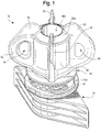
- FIG. 1 illustrates the completed closure assembly 20 with the overcap 28 installed in an initially closed condition on the fitment 24.
- FIG. 1 may be characterized as also illustrating the overcap 28 and fitment 24 in an initially assembled orientation which prevents, but can be subsequently operated to permit, communication therethrough.
- the overcap 28 is removed by the user from the fitment 28.
- the overcap 28 is unscrewed from the fitment 24 and lifted away so as to afford sufficient access to the fitment 24 (the fitment 24 being shown in FIG. 9 without the overcap 28 installed thereon).
- the user's initial or partial opening of the closure assembly 20 will permanently alter the physical condition of the overcap 28 so as to create or provide a "tamper-evident" indication to subsequent users of the initial opening or partial opening.
- the fitment 24 includes a spout 30 which defines an internal access passage 32 through the fitment 24 and which has a rim 33 ( FIG. 9 ) defining a distal open end from which a product can be discharged, or into which a product can be introduced.
- spout is used herein in the sense of a tall or a short, upwardly (i.e., axially outwardly) extending boss or other structure defining the access passage 32.
- the spout 30 also includes one cam 34 ( FIGS. 9 and 13 ) or cam follower 34, such as the illustrated helical thread 34.
- the fitment spout thread 34 could be regarded as either a cam per se or a cam follower per se for engaging a thread 70 on the overcap 28 ( FIG. 19 ) as described hereinafter. That is, if the fitment thread 34 is regarded as a cam, then the overcap thread 70 may be regarded as a cam follower. On the other hand, if the fitment thread 34 is regarded as the cam follower, then the overcap thread 70 may be regarded as the cam.
- the thread 34 and the thread 70 are each a dual lead helical thread having an identical predetermined pitch.
- the fitment 24 also includes at last one laterally projecting shear member 40.
- the shear members 40 may be located on, or as part of, the spout 30, or may be located below the spout 30.
- the structure of the spout threads 34 and shear members 40 is substantially the same as the structure of the spout threads 34 and shear members 40, respectively, as disclosed in the international patent application No. WO2015065481 .
- the receiving structure or fitment 24 may include a suitable structure for being mounted to a substance containment system (e.g., a collapsible, flexible pouch (not illustrated) or other structure of a system to which the closure assembly 20 is intended to be attached).
- a substance containment system e.g., a collapsible, flexible pouch (not illustrated) or other structure of a system to which the closure assembly 20 is intended to be attached.
- the bottom portion of the fitment 24 typically includes a suitable conventional or special, "boat-shaped,” heat-sealable base 25 ( FIG. 9 ) the details of which form no part of the broad aspects of the present invention).
- the base 25 can be attached to the open end of a pouch with suitable, conventional heat sealing techniques.
- the base 25 has a top end surface or outer end 26 ( FIGS. 9 and 13 ) at the top of the fitment base sides which are adapted to be heat sealed to the webs of thermoplastic material defining the side walls of the pouch (not illustrated).
- closure assembly receiving structure or fitment 24 to the container (not illustrated), or to another system, are contemplated. These other means could include, for example, adhesive.
- the access passage 32 in the spout 30 of the fitment 24 can be seen in FIG. 13 .
- the access passage 32 extends from the distal, outer end rim 33 of the spout 30 and through the rest of the fitment 24.
- the access passage 32 communicates with an opening of the pouch or bottle (not illustrated) or other system, and the passage 32 permits material (gases, fluids, solids, etc.) to pass between the exterior and the interior of the system. It is to be understood that the access passage 32 need not be circular as shown.
- the access passage 32 may be elliptical, polygonal, or some other regular or irregular shape.
- the spout 30 defines an exterior sealing surface in the form of an exterior shoulder 45 having a radially outwardly facing, cylindrical first portion sealing surface 45A and an upwardly facing, annular second portion sealing surface 45B.
- the spout 30 has an interior annular projection 47 that, in the particular illustrated embodiment, is located axially below the exterior shoulder 45, and that extends laterally inwardly into the access passage 32 to define an easily sealable, interior sealing surface 47A, which, in the presently preferred form illustrated, is generally cylindrical and faces radially inwardly.
- the distance D1 from the bottom of the interior sealing surface 47A to the top end surface 26 of the fitment base 25 is 5.46 mm
- the distance D2 defined between the top of the spout 30 and the top of the base 25 is 20.83 mm.
- D1 is less than half the distance D2.
- each shear member 40 has a leading edge 42 and a trailing edge 44.
- Each shear member 40 may alternatively be described as a shear fin.
- each shear fin or shear member 40 is relatively smooth to accommodate intentional or accidental contact of the shear member 40 by a user's finger and/or lip.
- the overcap 28 is adapted to be installed on the fitment 24 in an initially assembled orientation defining an initially fully closed condition. In this condition, a combination of the overcap 28 and fitment 24 together define an initially assembled orientation which prevents, but can be subsequently operated to permit, communication through the fitment.
- the operation to permit communication through the fitment 24 is the unscrewing of the overcap 28 from the fitment 24 as described hereinafter.
- the overcap 28 has a skirt 50 ( FIG. 9 ) for engaging at least a portion of the fitment spout 30 as can be seen in FIG. 7 .
- the upper end of the overcap skirt 50 terminates in a peripheral, annular end portion 56 around a recess 56A.
- the skirt 50 is defined by a generally cylindrical sleeve having a larger diameter, lower end portion 50A.
- the overcap skirt 50 and its lower end portion 50A define an open end (not numbered) into which the fitment spout 30 extends to accommodate relative rotation between the overcap 28 and the fitment 24.
- an internal clean out plug or seal plug 58 which has a frustoconical, exterior sealing surface 58A to sealingly engage the interior scaling surface 47A on the inside of the fitment spout 30 to establish a first seal when the overcap 28 and fitment 24 are in the initially assembled closed condition.
- the overcap plug 58 is closed at its bottom end by an end wall 59 ( FIG. 6 ) which defines the bottom of the overcap recess 56A and which also defines on its periphery a frustoconical surface or chamfer 60 for accommodating insertion of the lower end of the plug 58 into, and against, the fitment spout seal surface 47A ( FIG. 6 ) on the fitment spout projection 47.
- the design can also incorporate some flexibility in the spout annular projection 47 to accommodate insertion of the overcap plug 58.
- the overcap 28 has an annular space or channel 61 ( FIG. 19 ) defined between the plug 58 and the skirt 50 for accommodating the fitment spout 30 as can be seen in FIG. 6 .
- the skirt 50 of the overcap 28 has a compound sealing surface in the form of cylindrical first portion sealing surface 63A and an annular second portion sealing surface 638 for sealingly engaging the fitment spout shoulder seal cylindrical first portion sealing surface 45A and annular second portion sealing surface 45B, respectively, when the overcap 28 and fitment 24 are in the initially assembled orientation ( FIG. 6 ).
- the novel engagement of the sealing configuration as defined by the overcap 28 and fitment 24 provides certain advantages.
- the outer seal established by the overcap surfaces 63A, 63B with the fitment spout exterior shoulder sealing surfaces 45A, 45B can prevent, or at least inhibit, ingress of contaminants upwardly past the seal into the long thread region of the spout 30 prior to (and after) installation of the closure assembly 20 on a pouch or other system.
- the low location of the inner seal established by the engaged interior spout sealing surface 47A with the lower portion of the overcap plug sealing surface 58A can prevent, or at least inhibit, ingress of contaminants upwardly past the seal into the region around the inside and outside of the spout 30 prior to installation of the closure assembly 20 on a pouch or other system.
- the spout 30 may be relatively long (i.e., tall) in applications where it is desired to accommodate a person's mouth, including lips, for drinking a fluent product through the spout. Without an outer seal near the base of the spout 30 (as effected by engagement of the spout surfaces 45A and 45B with the overcap surfaces 63A and 63B, respectively), and without an inner seal near the lower end of the plug 58 (as effected by the engagement of the plug sealing surface 58A with the fitment spout sealing surface 47A), a relatively long length of the spout 30 would be susceptible to contamination prior to installation of the closure assembly 20 on a pouch or other containment system.
- the efficiency and efficacy of the cleaning (e.g., sterilization) process can be enhanced by employment of the engaged sealing surfaces 45A/63A, 45B/63B, and 47A/58A which cooperate to define a sealed off, internal region that may then not need to be sterilized (or otherwise cleaned) after delivery of the closed closure assembly 20 to the packager.
- the configuration of the long ("deep") overcap plug 58 and the engaging fitment spout interior seal surface 47A locates the inner or interior seal "low” in the spout, and that provides other advantages when the closure assembly 20 is used with containers (e.g., pouches) containing a product that could be adversely affected by the ingress of ambient atmosphere.
- containers e.g., pouches
- some types of pouches include a laminate layer of metal which has good barrier properties (e.g., low permeability) relative to ambient atmospheric gases.
- a thermoplastic closure assembly installed on such a type of pouch typically is more gas permeable than is the metal laminate pouch, and thus, such a thermoplastic closure assembly presents a lower barrier to atmospheric gases, including oxygen.
- thermoplastic closure assembly Some characteristics (e.g., color) of some products packaged in pouches can be adversely affected (e.g., change in color) by permeation of gases (e.g., oxygen) through portions of the thermoplastic closure assembly at the top of the pouch.
- gases e.g., oxygen
- the aspect of the present invention that relates to the overcap plug seal configuration which locates the overcap plug end wall 59 and the interior seal (defined by sealing surfaces 47A and 58A) near the bottom, inner end of the spout 30.
- the positions of the overcap plug end wall 59 and of the interior seal defined by the engaged seal surfaces 47A and 58A ( FIG. 6 ) at a relatively low elevation inside the spout 30 eliminate a large, internal, free volume in the spout above the product in the pouch to reduce the amount of atmospheric gases that are trapped in the spout above the product and that could adversely affect the product.
- closure assembly configuration has two seals (i.e., inner seal surfaces 47A/58A, and outer seal surfaces 45A763A, 45B/63B) to prevent gas ingress between the spout 30 and overcap 28.
- the closure assembly provides two annular wall structures (the annular wall of the skirt 50 and the annular wall of the spout 30) to impede the permeation of the ambient atmosphere oxygen or other gases.
- the lower part of the wall of the spout 30 extending vertically between the inner seal (at the engaged surfaces 47A and 58A) and the fitment base 25 (which typically would be sealed to the low permeability metal laminate pouch) provides only a single wall thickness of thermoplastic material as a barrier in that lower region, the length of spout wall in that lower region is considerably less than what would exist if the inner seal was provided higher up, or if the inner seal was completely omitted.
- the configuration of the spout 30 and overcap plug 58 of the present invention can reduce the amount of ambient atmospheric oxygen (and other gases) passing through the closure assembly 20 to the product -- thereby reducing the possibility of adverse effects on the product or reducing such adverse effects, per se.
- the overcap 28 also preferably includes tabs 62 on the outside of the overcap 28, and the tabs 62 are adapted to be engaged by a user's fingers and thumb to assist in rotating the overcap 28 relative to the fitment 24.
- each tab 62 defines an aperture 64 which minimizes the amount of material required for forming each tab 62 and which may provide an additional gripping feature to permit the user's fingers and/or thumb to better engage one or more of the tabs 62.
- an inside portion of the overcap skirt 50 defines the cam 70 or a cam follower 70 which, in the illustrated preferred embodiment, is the previously identified helical thread 70 for engaging the helical thread 34 on the fitment spout 30.
- the thread 70 could be regarded either as a cam, per se, or a cam follower, per se , for engaging the fitment thread 34. That is, if overcap thread 70 is regarded as the cam, then fitment thread 34 would be regarded as the cam follower. On the other hand, if the overcap thread 70 is regarded as the cam follower, then the fitment thread 34 would be regarded as the cam.
- the relative rotational movement between the overcap 28 and the fitment 24 could result from rotating the overcap 28 relative to the fitment 24 being held stationary, or could result from rotating the fitment 24 (and attached system (e.g., pouch or a bottle)) relative to the overcap 28 being held stationary, or could result from rotating both the overcap 28 and fitment24 (and attached system) simultaneously in opposite directions.
- each thread 34 and 70 is a dual lead helical thread having a predetermined pitch.
- the pitch is selected to provide an initial gap G1 ( FIG. 6 ) between the threads 34 and 70 when the overcap 28 and fitment 24 are in the initially assembled orientation ( FIGS. 6 and 7 ).
- the overcap thread 70 is defined in an upper portion of the skirt 50. Between the thread 70 and the open bottom end of the skirt 50, the skirt 50 has a lower, larger diameter, portion 50A that has a tamper-evident function and that defines two apertures 74 ( FIGS. 16 and 20 ) each extending in an arc around part of the skirt 50.
- the two apertures 74 are each divided into smaller holes or openings by one or more frangible bridges 78.
- a plurality of frangible bridges 78 extend across each aperture 74 to divide each aperture 74 into a plurality of smaller holes or openings that are each separated from an adjacent smaller hole or opening by one of seven frangible bridges 78.
- the skirt lower portion 50A of the overcap 28 defines two such elongate apertures 74A located 180° apart.
- Each such elongate aperture 74A is associated with the seven smaller circular holes which, together with the elongated opening 74A, comprise the one large aperture 74 divided by the seven frangible bridges 78.
- Each bridge 78 that is defined between two of the smaller adjacent holes has concave sides which define a bridge structure with a narrow middle portion between wider top and bottom end portions.
- each bridge 78 has a flat, or very slightly curving, interior surface, but each bridge 78 has an exterior surface which, as viewed in transverse cross section in FIG. 20 , defines a radially outwardly bulging configuration which can be impinged by, and cause a desirable turbulence in, a gas flow, such as during sterilization of the closure assembly 20 by a packager prior to installation of the closure assembly 20 on a container (not illustrated). This can enhance the efficiency of the sterilization process.
- each bridge 78 also minimizes the effect of restricted flow of molten plastic resin during molding of the overcap 28, and that accommodates a better filling pattern of the molten plastic resin flow during molding so as to provide a better mold fill with a reduced likelihood of creating undesirable voids or cavities. This provides a wider processing window with respect to the injection molding machine.
- the shape of the frangible bridge 78 is not difficult to mold, and provides a greater strength even though the bridge 78 is relatively thin at the narrowest point. This allows the designer to maximize the vertical height of the bridge 78.
- the opposite sides of the bridge 78 define the tapering shape leading to the narrow part of the bridge 78, and that shape accommodates a thicker, stronger shear member 40 in an adjacent portion of the aperture 74 when the overcap 28 is rotated relative to the fitment 24 as is described in detail hereinafter.
- the number of frangible bridges 78 extending across the aperture 74 to define the smaller holes may be fewer than seven or may be more than seven.
- most of the frangible bridges 78 have oppositely facing sides that each has a concave configuration that defines the above-described tapering shape which provides the above-described advantages.
- each tether web 94 defines an internal recess 96.
- Each recess 96 is radially inwardly open, and each recess 96 extends axially so that is axially open at the bottom open end of the skirt 50.
- the fitment 24 has two oppositely facing, 180° spaced-apart shear members 40
- the overcap skirt 50 has two sets of multiple-bridged apertures 74 divided by the frangible bridges 78 into smaller openings, and each of the two sets of apertures 74 and frangible bridges 78 is designed to interact with an associated one of the two shear members 40 as explained hereinafter.
- the lower edge of the skirt 50 has a generally circular flange 100 having two oppositely facing planar surfaces 102 which are 180° apart. These may be used as keys or guides by the manufacturer to establish a desired orientation during conveyance and assembly of overcap 28 with the fitment 24.
- the fitment 24 and the closure overcap 28 are preferably separately molded or otherwise provided as separate components.
- the manufacturer assembles the two components together by effecting relative axial movement between the two components so as to force the spout 30 of the fitment 24 into the skirt 50 of the overcap 28.
- At least a portion of at least one of the components is sufficiently flexible and resilient to accommodate the insertion of the fitment spout 30 into the open end of the overcap skirt 50 in the initially assembled orientation (see FIGS. 1 , 6 , 7 , and 8 ).
- each shear member 40 is located so that it is received in, and projects through, the elongate opening portion 74A of one of the apertures 74.
- the assembly process is preferably effected without relative rotation between the overcap 28 and fitment 24. However, in an alternate assembly process, the two components could be threaded together and screwed into the initially assembled orientation.
- the projecting shear members 40 in conjunction with the apertures 74 and 74A, can cause more desirable turbulence in a gas flow, such as during the sterilization of the closed closure assembly 20 by the packager prior to installation of the closure assembly 20 on a container (not illustrated). This can enhance the efficiency of the sterilization process.
- the fitment spout thread 34 does not initially engage the overcap skirt thread 70 in a manner that would effect axial movement of the overcap 28 during an initial amount of relative rotation between the fitment 24 and overcap 28. Rather, the fitment thread 34 and overcap thread 70 have a predetermined, identical pitch and are initially separated by a predetermined gap G1 ( FIG. 6 ) so that initial rotation of the overcap 28 in the opening direction (indicated by arrow 108 in FIG.
- the overcap 28 will initially rotate about the vertical axis, but will not initially also move axially outwardly up and along the fitment spout 30.
- the fitment thread 34 and overcap thread 70 are configured with the initial gap G1 so that they do not effect axial relative movement between the fitment 24 and overcap 28 until relative rotation has occurred over a predetermined angle of rotation (e.g., about 100°). Only after a sufficient amount of initial relative rotation do the threads 34 and 70 cooperate to cause the overcap 28 to move axially upwardly (outwardly) along the fitment spout 30.
- the amount of rotation required before the overcap 28 is axially moved relative to the fitment 24 may be designed to be greater or smaller than 100°, depending on the particular designs of the skirt apertures 74 and various other features of the closure assembly 20.
- each shear member 40 projects outwardly into, and preferably partially through, one of the associated overcap skirt apertures 74 and in particular, partially through the elongate portion 74A of the aperture 74 which is initially divided by the plurality of frangible bridges 78.
- the frangible bridges 78 sequentially move against the leading edge 42 of the associated shear member 40 and are severed by the shear member 40.
- the overcap thread 70 and the fitment thread 34 are initially not effective to cause axial movement of the overcap 28 until a predetermined amount of rotation has occurred (e.g., about 100°) as previously explained thus the overcap 28 initially only rotates, but does not initially move axially upwardly relative to the fitment 24.
- the user continues rotating the overcap 28 so that the projecting shear members 40 each sequentially sever the associated frangible bridges 78.
- each laterally projecting shear member 40 begins to engage the part of the tether web 94 between the last sheared frangible bridge 78/78A and the beginning of the elongate opening portion 74A of the other aperture 74.
- This engagement of the skirt tether webs 94 with the shear members 40 can cause the lower portion of the skirt 50 to deform radially outwardly (at least temporarily) in opposite directions (as described in the international patent application No. WO2015065481 ).
- the radial distortion and deformation of the lower portion of the skirt 50 be only elastic and temporary. In other applications, it may be desired to provide a design in which at least some amount of the radial distortion and deformation of the overcap 28 is a permanent, inelastic deformation. While the permanent radial deformation and distortion of the lower part of the skirt 50 of the overcap 28 might be desirable in some applications, and while such permanent radial distortion could provide evidence of the opening of, or at last an attempt to open, the closure 20, it may not be necessary or desired in other applications.
- each frangible bridge 78 preferably generates an audible click.
- the audible clicks may sound somewhat like the noise created when a conventional zipper is opened or closed. The user can tell from the sound that the frangible bridges 78 are being severed. Of course, the user can also visually observe the severing of the frangible bridges 78.
- each frangible bridge 78 may be more or less audible to the user. Although the generation of a sound that is particularly audible to the user may be preferred in some applications, that may not be desirable or needed in other applications.
- each frangible bridge 78 may also provide a slight tactile feedback so that a relatively rapid rotation of the overcap 28 through a first angle of rotation (e.g., 100°) can result in a generally continuous vibratory feeling or feedback that is sensed by the user who is opening the closure.
- a first angle of rotation e.g. 100°
- Such discernible tactile feedback while preferred in some applications, may not be desirable or needed in other applications.
- the overcap 28 As each shear member 40 begins to engage, and outwardly deform, the lower portion of the skirt 50 of the overcap 28, the fitment thread 34 and the overcap thread 70 begin to contact in a camming engagement that exerts an axial force on the overcap 28 tending to urge the overcap 28 axially upwardly relative to the fitment 24.
- the overcap 28 is not initially free to move upwardly relative to the fitment 24 because a portion of each shear member 40 still lies within the associated aperture 74 thereby preventing upward movement of the portion of the skirt 50 below the apertures 74.
- the overcap skirt 50 becomes subject to axial tension and begins to elongate very slightly-preferably within the elastic range of the material.
- each shear member 40 is laterally tapered so that it narrows toward its trailing end 44.
- the decreasing radial extent of each shear member 40 toward its trailing end 44 is such that, after sufficient rotation of the overcap 28 in the opening direction, each shear member 40 is no longer projecting into the overcap skirt aperture 74 and is no longer effective to positively resist the upward force being exerted by the lower portion of the skirt 50.
- the overcap skirt 50 which has been elastically stretched in the axial direction, is now able to overcome any existing frictional engagement with the shear members 40, and can spring upwardly slightly, and this causes the lower edges of the skirt apertures 74 to move upwardly past each shear member 40.
- the action of a lower portion of the skirt 50 springing upwardly relative to each shear member 40 is preferably accompanied by a physical sensation that is felt by the user when the user rotates the overcap 28 to the open condition.
- the user may sense that the overcap 28 is "jumping up” or “popping up” or “snapping up” relative to the fitment 24. This sudden movement of the overcap 28 in the upward direction is preferred so as to provide the user with a further indication of the continuation of the opening process, but such a feature is not a required or essential feature.
- each tether web 94 defining the recess 96 preferably remains outwardly distorted, but is not torn or severed.
- the lower portion of the skirt 50 below the apertures 74 remains tethered (attached) to the portion of the skirt 50 above the apertures 74 even though all of the frangible bridges 78 have been severed.
- the portion of the skirt 50 that has been radially outwardly deformed can now be pulled upwardly together with the rest of the overcap 28 by the action of the overcap thread 70 in camming engagement with the thread 34 of the fitment 24.
- the overcap 28 is moved axially (i.e., translated) further up and along the spout 30. Eventually, the threads 34 and 70 become disengaged, and the entire overcap 28 can be lifted upwardly off of the fitment 24 to open the closure assembly 20.
- each shear member 40 is adapted for guiding the overcap skirt 50 as it rides up and around the shear members 40 during the relative axially upward movement of the overcap 28 as the overcap 28 is being rotated by the user.
- each shear member 40 can function to help guide the overcap 28 over the shear members 40 when the manufacturer initially installs the overcap 28 on the fitment 24.
- the process for assembling the overcap 28 and the fitment 24 by the manufacturer could include the manufacturer merely pushing the overcap 28 down on the fitment 24 while both components are in proper rotational alignment for the initially assembled (closed) orientation ( FIGS. 1 and 9 ), and the flexibility of the components, especially the flexibility of the overcap 28, would accommodate such an installation.
- the overcap 28 could also be rotated as it is being pushed down on the fitment 24 so as to engage the fitment thread 34 with the overcap thread 70 with the rotation being terminated at the point when the azimuthal (i.e., rotational) alignment between the two components corresponds to the fully closed, initially assembled orientation,
- the overcap frangible bridges 78 are severed, and the overcap lower end may remain (and preferably remains) radially distorted, but the overcap 28 also remains a unitary structure without any separate tear-off pieces or bands being generated by the opening process.
- the structural and operational features of the preferred embodiment of the closure assembly 20 which prevent the formation of smaller, separate, discrete waste pieces are not an essential requirement of the broad aspects of the invention.
- the overcap 28 it may be desirable to design the overcap 28 so that after the overcap 28 has been opened and removed from the fitment 24, there remains some small amount of outward radial distortion or deformation along the lower edge of the skirt 50 which defines a somewhat elongate or oval shape (as viewed in plan from above or below). In other applications, it may not be desired to have a permanent deformation, and it may instead be desirable to design the overcap skirt 50 so that it generally remains with an original, undeformed attractive shape.
- the combination of the overcap 28 and fitment 24 can be designed to provide apertures and bridges to indicate that the overcap has been previously opened, or at least that an attempt was made to open the overcap -- however, such features are not essential to other broad aspects of the invention.
- closure assembly 20 of the present invention need not necessarily include all of the features that have been so far described.
- the number and shape of the frangible bridges 78, and the apertures 74, including openings defined between the frangible bridges 78 can be varied, or the tamper-evident features (e.g., bridges 78, apertures 74, and shear members 40) can be omitted altogether.
- the closure assembly 20 described herein includes the following two main concepts, concept 1 and concept 2, that are provided in combination with each other
Landscapes
- Engineering & Computer Science (AREA)
- Mechanical Engineering (AREA)
- Closures For Containers (AREA)
Description
- Not Applicable.
- Not applicable.
- Not applicable.
- The present invention relates to a closure assembly that can be installed on a containment system (e.g., a container such as a pouch, carton, etc.) to provide (1) a spout extending from the containment system, and (2) a removable overcap therefor. The invention is particularly suitable for use with a handheld pouch containing a fluid product (e.g., a drink product, baby formula, yogurt, food additive, pharmaceutical product, etc.) wherein the closure assembly is initially provided to a packager for sterilization with a sterilizing gas so as to create an aseptic closure assembly that the packager can then install on the pouch.
- Various types of packages, including those that employ a flexible, collapsible, pouch-type container (i.e., a pouch), are used for holding and dispensing a product, especially a fluid product. Such packages, including packages employing a pouch-type container, typically include a removable cover, cap, or overcap to initially prevent ingress of contaminants. More particularly, the package may include a closure assembly that has a projecting neck or spout through which the product can be poured, imbibed, or otherwise removed, and on which the overcap is initially installed. A pouch or carton type package typically has a closure assembly that includes a fitment for being sealed to the pouch or carton wall, and the fitment has an outwardly projecting spout through which the pouch contents can be discharged and which is adapted to receive a removable overcap for initially closing the spout. The fitment typically has an exterior male thread on the spout for cooperating with a female thread on the inside of the overcap.
- Typically, the fitment and overcap are initially made separately by a manufacturer who can provide them to a packager or filler either as separate components or screwed together to create a closed closure assembly. The separate components or the completed closure assembly are subsequently provided to a packager or filler for completing the manufacture of the package.
- In one method for making a flexible, collapsible, pouch-type package, the pouch is initially formed with an open top end, and while empty, is sealed at its open top end to the fitment component of the closure assembly prior to installation of the overcap. Subsequently, the pouch can be filled with product through the fitment open spout, and then the overcap can be installed in a closed condition on the fitment spout.
- In an alternate method for making a pouch-type package -- which is preferred when at least the closure assembly is to be sterilized (or otherwise cleaned) -- the packager or filler employs a "form, fill, and seal" operation to first form the pouch with an open top end, then fill the pouch with product through the pouch open top end, then insert the closed closure assembly in the pouch open top end, and lastly seal the top end of the pouch around the closed closure assembly.
- In some cases, a packager or filler may what to sterilize or otherwise clean the closure assembly before installing the closure assembly on the container. Some packagers or fillers typically clean or sterilize the packaging components (including a closed closure assembly) in a cleaning chamber (which may be, or may include, a sterilizing chamber) wherein a cleaning gas or sterilizing gas (e.g., hydrogen peroxide gas) flows through the chamber in contact with the packaging component or components.
-
GB 2 306 162 A - The inventors of the present invention have observed that a closed closure assembly (comprising a fitment with a projecting threaded spout having a threaded overcap initially mounted thereon) can be difficult to clean and/or sterilize in a cleaning system, including a hydrogen peroxide gas sterilizing system. The inventors of the present invention have determined that it would be desirable to provide an improved spout and overcap configuration for facilitating such cleaning.
- The inventors of the present invention have further determined that it would be advantageous to provide an assembly of a fitment with a projecting spout and a mating overcap that together would readily accommodate cleaning, especially hydrogen peroxide gas sterilization, in a way that would result in enhanced cleaning or sterilization of the assembly -- preferably a level of cleaning or sterilization sufficient to receive approval of a government body (e.g., the United States of America federal Food and Drug Administration ("FDA")) for use with food or pharmaceutical products.
- Closure assembly components are typically molded from polyethylene or polypropylene. Such a closure assembly can be installed by heat sealing the assembly to a polyethylene or polypropylene laminate layer of the pouch walls. Typically, the pouch also includes a laminate layer of metal foil which reduces the permeation or transmission of atmospheric oxygen (or other gases) through the pouch wall so as to minimize or reduce adverse effects of the oxygen (or other gases) on the product in the pouch. Such adverse effects depend on the nature of the product, and can include undesirable changes in the product color, for example, or other characteristics.
- Over time, oxygen (and/or other gases) can also pass from the external, ambient atmosphere through the wall of a closure spout and/or through the wall of a closure overcap, and then ultimately adversely affect a product in the package. The inventors of the present invention have observed that a closure assembly having a relatively long neck or spout would present an undesirably large wall area through which oxygen (or other gases) could pass and possibly adversely affect the product in the package.
- The inventors of the present invention have also determined that it would be desirable to provide a spout with a length sufficient to readily accommodate a person's mouth, including lips, during drinking from the container spout. Additionally, the inventors of the present invention have determined that it would be especially advantageous to provide a fitment spout and mating overcap with a structure that would minimize, or at least reduce, the portions of the spout and overcap that are in communication with the product so as to minimize, or at least reduce, the permeation of oxygen (and/or other gases) which, over time, could have an adverse effect on the product contained within the package.
- The inventors of the present invention have also discovered that it would be desirable to provide an improved spout and overcap that has been configured so as to exhibit one or more of the following attributes, features, or advantages:
- A. component configurations that can be manufactured and/or assembled without excessive difficulty or excessively complicated operations, and
- B. component configurations that can be manufactured and/or assembled without excessive cost.
- The present invention provides a combination of an overcap and a fitment for a container according to appended claim 1, which together in an initially assembled orientation prevent, but can be subsequently operated to permit, communication through the fitment.
- According to one general aspect of the invention, the fitment includes a spout that defines an access passage, an exterior sealing surface, and at least one laterally projecting shear member. The cap defines a skirt that extends over a portion of the spout. The skirt has a skirt sealing surface for engaging the fitment exterior sealing surface to create a seal when the cap and the fitment are in the initially assembled orientation. The cap further defines an aperture for initially receiving the shear member when the cap and fitment are in the initially assembled orientation. The cap also defines at least one frangible bridge that extends across a portion of the aperture for being severed by the shear member during relative rotation between the cap and fitment. The aperture and the shear member cooperate, when the cap and the fitment are in the initially assembled orientation and subjected to a flow of a sterilizing gas, to create turbulence in the sterilizing gas flow adjacent portions of the cap and the fitment to enhance sterilization thereof.
- Another aspect of the present invention also includes a closure assembly comprising a cap and a fitment for a container, which together in an initially assembled orientation prevent, but can be subsequently operated to permit, communication through the fitment. According to this other aspect of the invention, the fitment has a spout that defines an access passage, an interior sealing surface, and an exterior sealing surface. The cap has a top deck from which extends an elongate, hollow plug. The elongate, hollow plug has a plug sealing surface for engaging the fitment interior sealing surface to create a first seal when the cap and the fitment are in the initially assembled orientation. The cap also has a skirt extending over at least a portion of the spout, and has a skirt sealing surface for engaging the fitment exterior sealing surface to create a second seal when the cap and the fitment are in the initially assembled orientation. The cap also has an annular channel, that is defined between the elongate, hollow plug and the skirt, into which the fitment spout extends to accommodate relative rotation between the cap and the fitment.
- Other advantages and features of the present invention will become readily apparent from the following detailed description of the invention, from the claims, and from the accompanying drawings.
- In the accompanying drawings forming part of the specification, in which like numerals are employed to designate like parts throughout the same,
-
FIG. 1 is a perspective view taken from above a closure assembly of the present invention shown with a cap (also called an overcap) and a fitment in an initially assembled orientation for subsequently being installed on a pouch type container (not illustrated) in which a product may be stored -- the closure assembly, container, and product therein together constituting a "package"; -
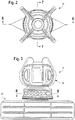
FIG. 2 is a top plan view of the closure assembly shown inFIG. 1 ; -
FIG. 3 is a front elevation view of the closure assembly shown inFIG. 1 ; -
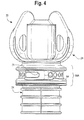
FIG. 4 is a right side elevation view of the closure assembly shown inFIG. 1 ; -
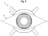
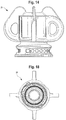
FIG. 5 is a bottom plan view of the closure assembly shown inFIG. 1 ; -
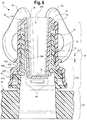
FIG. 6 is a cross-sectional view of the closure assembly taken along the plane 6-6 inFIG. 2 ; -
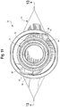
FIG. 7 is a cross-sectional view of the closure assembly taken along the plane 7-7 inFIG. 2 ; -
FIG. 8 is a cross-sectional view of the closure assembly taken along the plane 8-8 inFIG. 3 ; -
FIG. 9 is an exploded, perspective view of the closure assembly shown inFIG. 1 ; -
FIG. 10 is a front elevation view of just the fitment of the closure assembly shown inFIG. 9 ; -
FIG. 11 is a top plan view of the fitment shown inFIG. 10 ; -
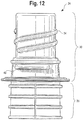
FIG. 12 is a right side elevation view of the fitment, shown inFIG. 10 ; -
FIG. 13 is a cross-sectional view of the fitment taken along the plane 13-13 inFIG. 11 ; -
FIG. 14 is an elevation view of just the overcap of the closure assembly shown inFIG. 9 ; -
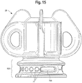
FIG. 15 is another elevation view of the overcap shown inFIG. 14 , but inFIG. 15 the overcap is shown rotated 90 degrees from the position of the overcap shown inFIG. 14 ; -
FIG. 16 is a front elevation view of the overcap shown inFIG. 14 ; -
FIG. 17 is a top plan view of the overcap shown inFIG. 14 ; -
FIG. 18 is a bottom plan view of the overcap shown inFIG. 14 ; -
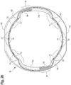
FIG. 19 is a cross-sectional view of the overcap taken along the plane 19-19 inFIG. 17 ; and -
FIG. 20 is a cross-sectional view of the overcap taken along the plane 20-20 inFIG. 16 . - While this invention is susceptible of embodiment in different forms, this specification and the accompanying drawings disclose only some specific embodiments as examples of the invention. The invention is not intended to be limited to the embodiments so described, and the scope of the invention will be pointed out in the appended claims.
- For ease of description, many figures illustrating the invention show a presently preferred embodiment of a closure assembly in the typical orientation that the closure assembly would have when it is installed at the opening of a container (such as, for example, a flexible pouch), and terms such as upper, lower, inward, outward, axial, lateral, etc., are used with reference to this orientation. It will be understood, however, that the closure assembly may be manufactured, stored, transported, used, and sold in an orientation other than the orientation described.
- The illustrated preferred embodiment of the closure assembly of this invention can be modified for use with a variety of conventional or special containers, the details of which, although not fully illustrated or described, would be apparent to those having skill in the art and an understanding of such containers. The particular containers, per se, that are described herein form no part of, and therefore are not intended to limit, the broad aspects of the present invention.
- The illustrated embodiment of the closure assembly will typically be used on a container in the form of a collapsible, flexible pouch that contains a material or substance (e.g., a product such as a fluent food (e.g., yogurt), drink substance, or lotion) that can be imbibed, dispensed, or otherwise removed, from the container through the opened closure assembly. The product may be, for example, a fluent material such as a liquid, cream, gel, powder, slurry, or paste. If the container and closure assembly are large enough, then the product could also be non-fluent, discrete pieces of material (e.g., food products such as nuts, candies, crackers, cookies, etc., or non-food products including various items, particles, granules, etc.) which can be removed through an open closure assembly by hand from a container, or scooped out of a container, or ladled out of a container, or poured out of a container. Such materials may be, for example, a food product, a personal care product, an industrial product, a household product, or other types of products. Such materials may be for internal or external use by humans or animals, or for other uses (e.g., activities involving medicine, manufacturing, commercial or household maintenance, construction, agriculture, etc.).
- An embodiment of a closure assembly, and components thereof, incorporating the present invention are illustrated in the Figures wherein the closure assembly is designated generally by
reference number 20. In the particular illustrated embodiment, theclosure assembly 20 is provided in the form of a separate closure assembly 20 (FIG. 1 ) which is especially suitable for being attached to a container (not illustrated), such as a flexible, collapsible pouch that would typically contain contents such as a product consisting of a fluent material. - Where the container has the form of a pouch, then the pouch, or a portion thereof, may be made from a material suitable for the intended application (e.g., a thin, flexible material for a pouch wherein such a material could be a polyethylene terephthalate (PET) film or a polyethylene film).
- In applications wherein the
closure assembly 20 will be mounted to, or installed on, a thermoplastic container (e.g., a flexible, collapsible pouch), it is contemplated that the closure assembly manufacturer would typically make the closure assembly components by molding the components from a thermoplastic polymer and would then assemble them together in an initially assembled orientation defining a fully closed condition. The closure assembly manufacturer would then ship theclosed closure assembly 20 to a container filler facility at another location where the container is either manufactured or otherwise provided, and where the container is filled with a product. However, for some applications, the components of theclosure assembly 20 could be shipped by the manufacturer in an unassembled condition to the filler facility where they could be assembled by the packager or filler before or during the process of manufacturing the completed package containing the product. - In some cases, a packager or filler may want to sterilize or otherwise clean the closure assembly components or the
closed closure assembly 20 before installing theclosure assembly 20 on the container. Some packagers or fillers typically clean or sterilize the packaging components (including a closure assembly 20) in a cleaning chamber (which may be, or may include, a sterilizing chamber) wherein a cleaning gas or sterilizing gas (e.g., hydrogen peroxide gas) flows through the chamber in contact with the packaging component or components. Theclosed closure assembly 20 of the present invention can accommodate cleaning, especially hydrogen peroxide gas sterilization, in a way that can result in enhanced cleaning or sterilization of theclosed closure assembly 20. - In the illustrated preferred embodiment of the invention, the closure assembly 20 (
FIG. 1 ) includes (1) alower element 24, which may also be characterized as a receiving structure, body, base, or fitment (FIG. 9 ), and (2 ) anupper element 28, which may also be characterized as a closing element, cover, cap, or overcap (FIG. 9 ) which is adapted to be installed on, and removed from, thelower element 24. Generally, the term "fitment" will be used throughout the specification and claims to refer to theelement 24, and the terms "overcap" or "cap" will be used throughout the specification and claims to refer to theelement 28. - The
fitment 24 and theovercap 28 are each preferably molded from a suitable thermoplastic material such as polyethylene, polypropylene, or the like. In a presently preferred form of theclosure assembly 20, thefitment 24 and theovercap 28 are preferably each molded separately from high density polyethylene (HDPE). Other materials may be employed instead. - The
fitment 24 and theovercap 28 would typically be separately molded by the manufacturer and assembled together to form theclosure assembly 20 for shipment to a packager or filler at another location for installation on a container (e.g., a flexible pouch (not illustrated) - - with or without sterilization (or other cleaning) being effected prior to installation. -
FIG. 1 illustrates the completedclosure assembly 20 with theovercap 28 installed in an initially closed condition on thefitment 24.FIG. 1 may be characterized as also illustrating theovercap 28 andfitment 24 in an initially assembled orientation which prevents, but can be subsequently operated to permit, communication therethrough. Typically, in order to permit communication through thefitment 24 of theclosure assembly 20, theovercap 28 is removed by the user from thefitment 28. In the preferred embodiment illustrated, theovercap 28 is unscrewed from thefitment 24 and lifted away so as to afford sufficient access to the fitment 24 (thefitment 24 being shown inFIG. 9 without theovercap 28 installed thereon). As explained hereinafter, in one preferred form of theclosure assembly 20, the user's initial or partial opening of theclosure assembly 20 will permanently alter the physical condition of theovercap 28 so as to create or provide a "tamper-evident" indication to subsequent users of the initial opening or partial opening. - With reference to
FIG. 9 , thefitment 24 includes aspout 30 which defines aninternal access passage 32 through thefitment 24 and which has a rim 33 (FIG. 9 ) defining a distal open end from which a product can be discharged, or into which a product can be introduced. The term "spout" is used herein in the sense of a tall or a short, upwardly (i.e., axially outwardly) extending boss or other structure defining theaccess passage 32. - In the illustrated embodiment, the
spout 30 also includes one cam 34 (FIGS. 9 and13 ) orcam follower 34, such as the illustratedhelical thread 34. Thefitment spout thread 34 could be regarded as either a cam per se or a cam follower per se for engaging athread 70 on the overcap 28 (FIG. 19 ) as described hereinafter. That is, if thefitment thread 34 is regarded as a cam, then theovercap thread 70 may be regarded as a cam follower. On the other hand, if thefitment thread 34 is regarded as the cam follower, then theovercap thread 70 may be regarded as the cam. In either case, it is to be realized that the relative rotational movement between theovercap 28 and thefitment 24 could result from rotating theovercap 28 relative to thefitment 24 being held stationary, or could result from rotating the fitment 24 (along with the attached container system) relative to theovercap 28 being held stationary, or could result from rotating both theovercap 28 andfitment 24 simultaneously in opposite directions. In the illustrated preferred embodiment, thethread 34 and thethread 70 are each a dual lead helical thread having an identical predetermined pitch. - The
fitment 24 also includes at last one laterally projectingshear member 40. In the preferred embodiment illustrated inFIGS. 8 ,9 , and14 there are two such laterally projectingshear members 40 located below thethread 34. Theshear members 40 may be located on, or as part of, thespout 30, or may be located below thespout 30. The structure of thespout threads 34 andshear members 40 is substantially the same as the structure of thespout threads 34 andshear members 40, respectively, as disclosed in the international patent application No.WO2015065481 . - Opposite the distal open end of the fitment access passage 32 (
FIG. 9 ), the receiving structure orfitment 24 may include a suitable structure for being mounted to a substance containment system (e.g., a collapsible, flexible pouch (not illustrated) or other structure of a system to which theclosure assembly 20 is intended to be attached). For use with a collapsible, flexible pouch, the bottom portion of thefitment 24 typically includes a suitable conventional or special, "boat-shaped," heat-sealable base 25 (FIG. 9 ) the details of which form no part of the broad aspects of the present invention). The base 25 can be attached to the open end of a pouch with suitable, conventional heat sealing techniques. Thebase 25 has a top end surface or outer end 26 (FIGS. 9 and13 ) at the top of the fitment base sides which are adapted to be heat sealed to the webs of thermoplastic material defining the side walls of the pouch (not illustrated). - Further, other means of attaching the closure assembly receiving structure or
fitment 24 to the container (not illustrated), or to another system, are contemplated. These other means could include, for example, adhesive. - The
access passage 32 in thespout 30 of thefitment 24 can be seen inFIG. 13 . Theaccess passage 32 extends from the distal, outer end rim 33 of thespout 30 and through the rest of thefitment 24. Theaccess passage 32 communicates with an opening of the pouch or bottle (not illustrated) or other system, and thepassage 32 permits material (gases, fluids, solids, etc.) to pass between the exterior and the interior of the system. It is to be understood that theaccess passage 32 need not be circular as shown. Theaccess passage 32 may be elliptical, polygonal, or some other regular or irregular shape. - With reference to
FIG. 13 , thespout 30 defines an exterior sealing surface in the form of anexterior shoulder 45 having a radially outwardly facing, cylindrical firstportion sealing surface 45A and an upwardly facing, annular second portion sealing surface 45B. - Further, with reference to
FIG. 13 , thespout 30 has an interiorannular projection 47 that, in the particular illustrated embodiment, is located axially below theexterior shoulder 45, and that extends laterally inwardly into theaccess passage 32 to define an easily sealable,interior sealing surface 47A, which, in the presently preferred form illustrated, is generally cylindrical and faces radially inwardly. - With reference to
FIG. 13 , for one embodiment that has been designed, the distance D1 from the bottom of theinterior sealing surface 47A to thetop end surface 26 of thefitment base 25 is 5.46 mm, and the distance D2 defined between the top of thespout 30 and the top of thebase 25 is 20.83 mm. D1 is less than half the distance D2. - As can be seen in
FIG. 11 , eachshear member 40 has aleading edge 42 and a trailingedge 44. Eachshear member 40 may alternatively be described as a shear fin. Preferably, each shear fin orshear member 40 is relatively smooth to accommodate intentional or accidental contact of theshear member 40 by a user's finger and/or lip. - The
overcap 28 is adapted to be installed on thefitment 24 in an initially assembled orientation defining an initially fully closed condition. In this condition, a combination of theovercap 28 andfitment 24 together define an initially assembled orientation which prevents, but can be subsequently operated to permit, communication through the fitment. The operation to permit communication through thefitment 24 is the unscrewing of theovercap 28 from thefitment 24 as described hereinafter. - In the illustrated preferred embodiment, the
overcap 28 has a skirt 50 (FIG. 9 ) for engaging at least a portion of thefitment spout 30 as can be seen inFIG. 7 . Further, as can be seen inFIG. 9 , the upper end of theovercap skirt 50 terminates in a peripheral,annular end portion 56 around arecess 56A. As can be seen inFIGS. 6 and9 , theskirt 50 is defined by a generally cylindrical sleeve having a larger diameter,lower end portion 50A. With reference toFIGS. 3 and6 , theovercap skirt 50 and itslower end portion 50A define an open end (not numbered) into which thefitment spout 30 extends to accommodate relative rotation between theovercap 28 and thefitment 24. - As can be seen in
FIG. 6 , depending downwardly from the inside of theovercap 28 is an internal clean out plug or sealplug 58 which has a frustoconical,exterior sealing surface 58A to sealingly engage theinterior scaling surface 47A on the inside of thefitment spout 30 to establish a first seal when theovercap 28 andfitment 24 are in the initially assembled closed condition. - The
overcap plug 58 is closed at its bottom end by an end wall 59 (FIG. 6 ) which defines the bottom of theovercap recess 56A and which also defines on its periphery a frustoconical surface orchamfer 60 for accommodating insertion of the lower end of theplug 58 into, and against, the fitmentspout seal surface 47A (FIG. 6 ) on thefitment spout projection 47. The design can also incorporate some flexibility in the spoutannular projection 47 to accommodate insertion of theovercap plug 58. - The
overcap 28 has an annular space or channel 61 (FIG. 19 ) defined between theplug 58 and theskirt 50 for accommodating thefitment spout 30 as can be seen inFIG. 6 . - As can be seen in
FIGS. 6 and19 , theskirt 50 of theovercap 28 has a compound sealing surface in the form of cylindrical firstportion sealing surface 63A and an annular secondportion sealing surface 638 for sealingly engaging the fitment spout shoulder seal cylindrical firstportion sealing surface 45A and annular second portion sealing surface 45B, respectively, when theovercap 28 andfitment 24 are in the initially assembled orientation (FIG. 6 ). - The novel engagement of the sealing configuration as defined by the
overcap 28 andfitment 24 provides certain advantages. In particular, with reference toFIG. 6 , the outer seal established by the overcap surfaces 63A, 63B with the fitment spout exterior shoulder sealing surfaces 45A, 45B can prevent, or at least inhibit, ingress of contaminants upwardly past the seal into the long thread region of thespout 30 prior to (and after) installation of theclosure assembly 20 on a pouch or other system. - Also, as seen in
FIG. 6 , the low location of the inner seal established by the engaged interiorspout sealing surface 47A with the lower portion of the overcapplug sealing surface 58A can prevent, or at least inhibit, ingress of contaminants upwardly past the seal into the region around the inside and outside of thespout 30 prior to installation of theclosure assembly 20 on a pouch or other system. - The
spout 30 may be relatively long (i.e., tall) in applications where it is desired to accommodate a person's mouth, including lips, for drinking a fluent product through the spout. Without an outer seal near the base of the spout 30 (as effected by engagement of the spout surfaces 45A and 45B with the overcap surfaces 63A and 63B, respectively), and without an inner seal near the lower end of the plug 58 (as effected by the engagement of theplug sealing surface 58A with the fitmentspout sealing surface 47A), a relatively long length of thespout 30 would be susceptible to contamination prior to installation of theclosure assembly 20 on a pouch or other containment system. If a packager wants to sterilize (or otherwise clean) the closure assembly 20 (comprising the assembledfitment 24 and overcap 28), then the efficiency and efficacy of the cleaning (e.g., sterilization) process can be enhanced by employment of the engaged sealingsurfaces 45A/63A, 45B/63B, and 47A/58A which cooperate to define a sealed off, internal region that may then not need to be sterilized (or otherwise cleaned) after delivery of theclosed closure assembly 20 to the packager. - The configuration of the long ("deep")
overcap plug 58 and the engaging fitment spoutinterior seal surface 47A locates the inner or interior seal "low" in the spout, and that provides other advantages when theclosure assembly 20 is used with containers (e.g., pouches) containing a product that could be adversely affected by the ingress of ambient atmosphere. For example, some types of pouches include a laminate layer of metal which has good barrier properties (e.g., low permeability) relative to ambient atmospheric gases. However, a thermoplastic closure assembly installed on such a type of pouch typically is more gas permeable than is the metal laminate pouch, and thus, such a thermoplastic closure assembly presents a lower barrier to atmospheric gases, including oxygen. - Some characteristics (e.g., color) of some products packaged in pouches can be adversely affected (e.g., change in color) by permeation of gases (e.g., oxygen) through portions of the thermoplastic closure assembly at the top of the pouch. Such undesirable effects can be reduced by the aspect of the present invention that relates to the overcap plug seal configuration which locates the overcap plug
end wall 59 and the interior seal (defined by sealingsurfaces spout 30. - In particular, the positions of the overcap plug
end wall 59 and of the interior seal defined by the engagedseal surfaces FIG. 6 ) at a relatively low elevation inside thespout 30 eliminate a large, internal, free volume in the spout above the product in the pouch to reduce the amount of atmospheric gases that are trapped in the spout above the product and that could adversely affect the product. - Further, the closure assembly configuration has two seals (i.e., inner seal surfaces 47A/58A, and outer seal surfaces 45A763A, 45B/63B) to prevent gas ingress between the
spout 30 andovercap 28. - Additionally, above the two seals, the closure assembly the configuration provides two annular wall structures (the annular wall of the
skirt 50 and the annular wall of the spout 30) to impede the permeation of the ambient atmosphere oxygen or other gases. - Although the lower part of the wall of the
spout 30 extending vertically between the inner seal (at the engagedsurfaces spout 30 and overcap plug 58 of the present invention can reduce the amount of ambient atmospheric oxygen (and other gases) passing through theclosure assembly 20 to the product -- thereby reducing the possibility of adverse effects on the product or reducing such adverse effects, per se. - Preferably, as can be seen in
FIGS. 1 and6 , theovercap 28 also preferably includestabs 62 on the outside of theovercap 28, and thetabs 62 are adapted to be engaged by a user's fingers and thumb to assist in rotating theovercap 28 relative to thefitment 24. In the preferred embodiment, as illustrated inFIG. 1 , eachtab 62 defines anaperture 64 which minimizes the amount of material required for forming eachtab 62 and which may provide an additional gripping feature to permit the user's fingers and/or thumb to better engage one or more of thetabs 62. - With reference to
FIG. 6 , an inside portion of theovercap skirt 50 defines thecam 70 or acam follower 70 which, in the illustrated preferred embodiment, is the previously identifiedhelical thread 70 for engaging thehelical thread 34 on thefitment spout 30. Thethread 70 could be regarded either as a cam, per se, or a cam follower, per se, for engaging thefitment thread 34. That is, ifovercap thread 70 is regarded as the cam, thenfitment thread 34 would be regarded as the cam follower. On the other hand, if theovercap thread 70 is regarded as the cam follower, then thefitment thread 34 would be regarded as the cam. In either case, it is to be realized that the relative rotational movement between theovercap 28 and thefitment 24 could result from rotating theovercap 28 relative to thefitment 24 being held stationary, or could result from rotating the fitment 24 (and attached system (e.g., pouch or a bottle)) relative to theovercap 28 being held stationary, or could result from rotating both theovercap 28 and fitment24 (and attached system) simultaneously in opposite directions. - In the illustrated preferred embodiment, each
thread FIG. 6 ) between thethreads overcap 28 andfitment 24 are in the initially assembled orientation (FIGS. 6 and7 ). - In the preferred embodiment illustrated in
FIGS. 6 and7 , theovercap thread 70 is defined in an upper portion of theskirt 50. Between thethread 70 and the open bottom end of theskirt 50, theskirt 50 has a lower, larger diameter,portion 50A that has a tamper-evident function and that defines two apertures 74 (FIGS. 16 and20 ) each extending in an arc around part of theskirt 50. The twoapertures 74 are each divided into smaller holes or openings by one or morefrangible bridges 78. - In the preferred embodiment illustrated in
FIG. 16 , a plurality offrangible bridges 78 extend across eachaperture 74 to divide eachaperture 74 into a plurality of smaller holes or openings that are each separated from an adjacent smaller hole or opening by one of sevenfrangible bridges 78. With reference toFIGS. 15 and20 , there are seven of the smaller openings which are small circular holes, but eachaperture 74 also has another portion, which is designated 74A inFIG. 15 and20 , that is larger than each of the seven circular holes and that has a generally elongate shape or oval shape. - In the preferred embodiment illustrated, and with reference to
FIGS. 16 ,19 , and20 , the skirtlower portion 50A of theovercap 28 defines two suchelongate apertures 74A located 180° apart. Each suchelongate aperture 74A is associated with the seven smaller circular holes which, together with theelongated opening 74A, comprise the onelarge aperture 74 divided by the sevenfrangible bridges 78. - Each
bridge 78 that is defined between two of the smaller adjacent holes has concave sides which define a bridge structure with a narrow middle portion between wider top and bottom end portions. With reference toFIG. 20 , eachbridge 78 has a flat, or very slightly curving, interior surface, but eachbridge 78 has an exterior surface which, as viewed in transverse cross section inFIG. 20 , defines a radially outwardly bulging configuration which can be impinged by, and cause a desirable turbulence in, a gas flow, such as during sterilization of theclosure assembly 20 by a packager prior to installation of theclosure assembly 20 on a container (not illustrated). This can enhance the efficiency of the sterilization process. - The arcuate shape of bridge narrow middle portion between the top and bottom end portions of each
bridge 78 also minimizes the effect of restricted flow of molten plastic resin during molding of theovercap 28, and that accommodates a better filling pattern of the molten plastic resin flow during molding so as to provide a better mold fill with a reduced likelihood of creating undesirable voids or cavities. This provides a wider processing window with respect to the injection molding machine. - The shape of the
frangible bridge 78 is not difficult to mold, and provides a greater strength even though thebridge 78 is relatively thin at the narrowest point. This allows the designer to maximize the vertical height of thebridge 78. The opposite sides of thebridge 78 define the tapering shape leading to the narrow part of thebridge 78, and that shape accommodates a thicker,stronger shear member 40 in an adjacent portion of theaperture 74 when theovercap 28 is rotated relative to thefitment 24 as is described in detail hereinafter. - There may be fewer than seven circular holes defining part of the
aperture 74, or there may be more than seven such circular holes. That is, the number offrangible bridges 78 extending across theaperture 74 to define the smaller holes may be fewer than seven or may be more than seven. As viewed inFIGS. 15 and16 , most of thefrangible bridges 78 have oppositely facing sides that each has a concave configuration that defines the above-described tapering shape which provides the above-described advantages. - As can be seen in
FIGS. 9 ,15 ,16 , and20 , the upper portion of theovercap skirt 50A is joined by at least one non-frangible, but deformable,tether web 94 to the bottom end portion of theskirt 50. In the preferred embodiment, there are twosuch tether webs 94 located about 180° apart. As can be seen inFIG. 20 , eachtether web 94 defines aninternal recess 96. Eachrecess 96 is radially inwardly open, and eachrecess 96 extends axially so that is axially open at the bottom open end of theskirt 50. - In the preferred embodiment illustrated in
FIGS. 1 and8 , thefitment 24 has two oppositely facing, 180° spaced-apartshear members 40, and theovercap skirt 50 has two sets of multiple-bridgedapertures 74 divided by thefrangible bridges 78 into smaller openings, and each of the two sets ofapertures 74 andfrangible bridges 78 is designed to interact with an associated one of the twoshear members 40 as explained hereinafter. - As can be seen in
FIGS. 1 and20 , the lower edge of theskirt 50 has a generallycircular flange 100 having two oppositely facingplanar surfaces 102 which are 180° apart. These may be used as keys or guides by the manufacturer to establish a desired orientation during conveyance and assembly ofovercap 28 with thefitment 24. - Initially, the
fitment 24 and theclosure overcap 28 are preferably separately molded or otherwise provided as separate components. Subsequently, in a preferred process, the manufacturer assembles the two components together by effecting relative axial movement between the two components so as to force thespout 30 of thefitment 24 into theskirt 50 of theovercap 28. At least a portion of at least one of the components (typically theskirt 50 of the overcap 28), is sufficiently flexible and resilient to accommodate the insertion of thefitment spout 30 into the open end of theovercap skirt 50 in the initially assembled orientation (seeFIGS. 1 ,6 ,7 , and8 ). In the initially assembled orientation, eachshear member 40 is located so that it is received in, and projects through, theelongate opening portion 74A of one of theapertures 74. The assembly process is preferably effected without relative rotation between theovercap 28 andfitment 24. However, in an alternate assembly process, the two components could be threaded together and screwed into the initially assembled orientation. - The projecting
shear members 40, in conjunction with theapertures closed closure assembly 20 by the packager prior to installation of theclosure assembly 20 on a container (not illustrated). This can enhance the efficiency of the sterilization process. - After the assembly of the
fitment 24 andovercap 28 in the initially assembled orientation (which is the initial, fully closed condition), if relative rotation is effected between the two components in an "unscrewing" or "opening" direction, then thefitment spout thread 34 does not initially engage theovercap skirt thread 70 in a manner that would effect axial movement of theovercap 28 during an initial amount of relative rotation between thefitment 24 andovercap 28. Rather, thefitment thread 34 andovercap thread 70 have a predetermined, identical pitch and are initially separated by a predetermined gap G1 (FIG. 6 ) so that initial rotation of theovercap 28 in the opening direction (indicated byarrow 108 inFIG. 8 ) relative to thefitment 24 will not initially cause an upward, axial movement of theovercap 28 owing to the gap G1 (FIG. 6 ). Such a thread arrangement and operation thereof are disclosed in the international patent application No.WO2015065481 . In the particular form of the closure assembly illustrated, thethread 70 will not engage the upwardly facing camming surface of thefitment thread 34 until theovercap 28 has been rotated about 100° from the initially closed position illustrated inFIG. 6 . Thus, the first approximately 100° of rotation of theovercap 28 relative to thefitment 24 does not immediately cause engagement of theovercap thread 70 with thefitment thread 34 in a way that would cause axial translation (i.e., axial movement) of theovercap 28. - Continued rotation of the
overcap 28 away from the initially assembled orientation shown inFIGS. 1 and6 will cause the gap G1 (FIG. 6 ) between theovercap thread 34 and thefitment thread 70 to begin to decrease to a smaller gap, and further rotation of theovercap 28 reduces the gap further until, after about 100° of rotation of theovercap 28 relative to thefitment 24, the gap G1 is zero. The arrangement of thethreads - In view of the initial thread arrangement with the gap G1 (
FIG. 6 ), if a user attempts to open theovercap 28 by rotating theovercap 28 in the counterclockwise direction as indicated by thearrows 108 inFIG. 8 , then theovercap 28 will initially rotate about the vertical axis, but will not initially also move axially outwardly up and along thefitment spout 30. Thefitment thread 34 andovercap thread 70 are configured with the initial gap G1 so that they do not effect axial relative movement between thefitment 24 andovercap 28 until relative rotation has occurred over a predetermined angle of rotation (e.g., about 100°). Only after a sufficient amount of initial relative rotation do thethreads overcap 28 to move axially upwardly (outwardly) along thefitment spout 30. - The amount of rotation required before the
overcap 28 is axially moved relative to thefitment 24 may be designed to be greater or smaller than 100°, depending on the particular designs of theskirt apertures 74 and various other features of theclosure assembly 20. - In the initially assembled orientation illustrated in
FIGS. 1 and8 , eachshear member 40 projects outwardly into, and preferably partially through, one of the associatedovercap skirt apertures 74 and in particular, partially through theelongate portion 74A of theaperture 74 which is initially divided by the plurality offrangible bridges 78. As the relative rotation is effected between theovercap 28 and thefitment 24, typically by a user grasping and rotating theovercap 28 in the counterclockwise direction indicated by the arrows 108 (FIG. 8 ), thefrangible bridges 78 sequentially move against the leadingedge 42 of the associatedshear member 40 and are severed by theshear member 40. - As the user continues to rotate the
overcap 28 in the counterclockwise direction as indicated by thearrows 108 inFIG. 8 , theovercap thread 70 and thefitment thread 34 are initially not effective to cause axial movement of theovercap 28 until a predetermined amount of rotation has occurred (e.g., about 100°) as previously explained thus theovercap 28 initially only rotates, but does not initially move axially upwardly relative to thefitment 24. The user continues rotating theovercap 28 so that the projectingshear members 40 each sequentially sever the associatedfrangible bridges 78. After the lastfrangible bridge 78 has been severed, the leadingend 42 of each laterally projectingshear member 40 begins to engage the part of thetether web 94 between the last shearedfrangible bridge 78/78A and the beginning of theelongate opening portion 74A of theother aperture 74. This engagement of theskirt tether webs 94 with theshear members 40 can cause the lower portion of theskirt 50 to deform radially outwardly (at least temporarily) in opposite directions (as described in the international patent application No.WO2015065481 ). This causes a radial distortion (which may be temporary or permanent) in the overcap lower portion of the skirt 50 (especially at the tether webs 94), and this radial distortion is readily apparent to the user as the user continues to rotate theovercap 28 in the opening direction (indicated by therotational arrows 108 inFIG. 8 ). - In some applications, it may be desired that the radial distortion and deformation of the lower portion of the
skirt 50 be only elastic and temporary. In other applications, it may be desired to provide a design in which at least some amount of the radial distortion and deformation of theovercap 28 is a permanent, inelastic deformation. While the permanent radial deformation and distortion of the lower part of theskirt 50 of theovercap 28 might be desirable in some applications, and while such permanent radial distortion could provide evidence of the opening of, or at last an attempt to open, theclosure 20, it may not be necessary or desired in other applications. - During the opening process, as the
overcap 28 is rotated (in the opening direction indicated by thearrows 108 inFIG. 8 ) and as thefrangible bridges 78 are severed by theshear members 40, the severing of eachfrangible bridge 78 preferably generates an audible click. As thefrangible bridges 78 are sequentially severed, the audible clicks may sound somewhat like the noise created when a conventional zipper is opened or closed. The user can tell from the sound that thefrangible bridges 78 are being severed. Of course, the user can also visually observe the severing of the frangible bridges 78. Depending on the material from which theovercap 28 is molded, and depending on the particular thickness and/or shape of eachfrangible bridge 78, the sound generated by the severing of eachfrangible bridge 78 may be more or less audible to the user. Although the generation of a sound that is particularly audible to the user may be preferred in some applications, that may not be desirable or needed in other applications. - As the
frangible bridges 78 are severed, whether or not a sound is heard by the user, the severing of eachfrangible bridge 78 may also provide a slight tactile feedback so that a relatively rapid rotation of theovercap 28 through a first angle of rotation (e.g., 100°) can result in a generally continuous vibratory feeling or feedback that is sensed by the user who is opening the closure. Such discernible tactile feedback, while preferred in some applications, may not be desirable or needed in other applications. - As each
shear member 40 begins to engage, and outwardly deform, the lower portion of theskirt 50 of theovercap 28, thefitment thread 34 and theovercap thread 70 begin to contact in a camming engagement that exerts an axial force on theovercap 28 tending to urge theovercap 28 axially upwardly relative to thefitment 24. However, theovercap 28 is not initially free to move upwardly relative to thefitment 24 because a portion of eachshear member 40 still lies within the associatedaperture 74 thereby preventing upward movement of the portion of theskirt 50 below theapertures 74. Thus, theovercap skirt 50 becomes subject to axial tension and begins to elongate very slightly-preferably within the elastic range of the material. - Continued rotation of the
overcap 28 tends to urge theovercap 28 axially upward while causing the overcap recesses 96 (FIGS. 8 and20 ) to be moved adjacent theshear members 40, and eachrecess 96 in thedeformed tether web 94 accommodates the largest radial dimension of eachshear member 40. As can be seen inFIG. 11 , eachshear member 40 is laterally tapered so that it narrows toward its trailingend 44. The decreasing radial extent of eachshear member 40 toward its trailingend 44 is such that, after sufficient rotation of theovercap 28 in the opening direction, eachshear member 40 is no longer projecting into theovercap skirt aperture 74 and is no longer effective to positively resist the upward force being exerted by the lower portion of theskirt 50. When theshear members 40 no longer project into theskirt apertures 74, theovercap skirt 50, which has been elastically stretched in the axial direction, is now able to overcome any existing frictional engagement with theshear members 40, and can spring upwardly slightly, and this causes the lower edges of theskirt apertures 74 to move upwardly past eachshear member 40. - In the illustrated embodiment, the action of a lower portion of the
skirt 50 springing upwardly relative to eachshear member 40 is preferably accompanied by a physical sensation that is felt by the user when the user rotates theovercap 28 to the open condition. The user may sense that theovercap 28 is "jumping up" or "popping up" or "snapping up" relative to thefitment 24. This sudden movement of theovercap 28 in the upward direction is preferred so as to provide the user with a further indication of the continuation of the opening process, but such a feature is not a required or essential feature. - As the user continues to rotate the
overcap 28, eachtether web 94 defining therecess 96 preferably remains outwardly distorted, but is not torn or severed. Thus, the lower portion of theskirt 50 below theapertures 74 remains tethered (attached) to the portion of theskirt 50 above theapertures 74 even though all of thefrangible bridges 78 have been severed. Thus, the portion of theskirt 50 that has been radially outwardly deformed can now be pulled upwardly together with the rest of theovercap 28 by the action of theovercap thread 70 in camming engagement with thethread 34 of thefitment 24. And, upon further rotation of theovercap 28, theovercap 28 is moved axially (i.e., translated) further up and along thespout 30. Eventually, thethreads entire overcap 28 can be lifted upwardly off of thefitment 24 to open theclosure assembly 20. - It will be noted that the trailing
edge 44 of eachshear member 40 is adapted for guiding theovercap skirt 50 as it rides up and around theshear members 40 during the relative axially upward movement of theovercap 28 as theovercap 28 is being rotated by the user. - Also, the trailing
edge 44 of eachshear member 40 can function to help guide theovercap 28 over theshear members 40 when the manufacturer initially installs theovercap 28 on thefitment 24. - The process for assembling the
overcap 28 and thefitment 24 by the manufacturer could include the manufacturer merely pushing theovercap 28 down on thefitment 24 while both components are in proper rotational alignment for the initially assembled (closed) orientation (FIGS. 1 and9 ), and the flexibility of the components, especially the flexibility of theovercap 28, would accommodate such an installation. - In another possible method of assembling the
closure assembly 20, theovercap 28 could also be rotated as it is being pushed down on thefitment 24 so as to engage thefitment thread 34 with theovercap thread 70 with the rotation being terminated at the point when the azimuthal (i.e., rotational) alignment between the two components corresponds to the fully closed, initially assembled orientation, - It will also be appreciated that when the preferred embodiment of the
overcap 28 is initially removed by the user from thefitment 24, the overcapfrangible bridges 78 are severed, and the overcap lower end may remain (and preferably remains) radially distorted, but theovercap 28 also remains a unitary structure without any separate tear-off pieces or bands being generated by the opening process. As a result, there are no small, separate bits of theovercap 28 that could be a choking hazard for children or that would have to be separately recovered and retained for disposal. However, the structural and operational features of the preferred embodiment of theclosure assembly 20 which prevent the formation of smaller, separate, discrete waste pieces are not an essential requirement of the broad aspects of the invention. - In some applications, it may be desirable to design the
overcap 28 so that after theovercap 28 has been opened and removed from thefitment 24, there remains some small amount of outward radial distortion or deformation along the lower edge of theskirt 50 which defines a somewhat elongate or oval shape (as viewed in plan from above or below). In other applications, it may not be desired to have a permanent deformation, and it may instead be desirable to design theovercap skirt 50 so that it generally remains with an original, undeformed attractive shape. - The above-described operation of initially assembling, and subsequently opening, the tamper-evident closure assembly is also described in the international patent application No. PWO2015065481.
- It will be appreciated that according to the broad principles of one aspect of the present invention, the combination of the
overcap 28 andfitment 24 can be designed to provide apertures and bridges to indicate that the overcap has been previously opened, or at least that an attempt was made to open the overcap -- however, such features are not essential to other broad aspects of the invention. - It will be appreciated that the
closure assembly 20 of the present invention need not necessarily include all of the features that have been so far described. For example, it will be appreciated that according to some general aspects of the present invention relating to the closure assembly overcap/fitment sealing configurations, the number and shape of thefrangible bridges 78, and theapertures 74, including openings defined between thefrangible bridges 78, can be varied, or the tamper-evident features (e.g., bridges 78,apertures 74, and shear members 40) can be omitted altogether. - The
closure assembly 20 described herein includes the following two main concepts, concept 1 andconcept 2, that are provided in combination with each other - Concept 1 -- the combination of
- a) at least an outer seal established by engagement of the fitment (e.g., the sealing surfaces 45A, 45B) with the overcap (e.g., sealing
surfaces 63A, 63B), and - b) the structure of the fitment
spout shear members 40 andovercap apertures 74 that increase turbulence in a cleaning gas flow stream (e.g., hydrogen peroxide gas in a sterilization chamber) to enhance the cleaning and/or efficiency of the cleaning process; and
- a) at least an outer seal established by engagement of the fitment (e.g., the sealing surfaces 45A, 45B) with the overcap (e.g., sealing
-
Concept 2 -- the configuration and combination of first and second seals established by thefitment 24 andovercap 28 -- namely- a) the
fitment sealing surface 47A engaging the sealingsurface 58A on the elongatehollow plug 58 of theovercap 28 to establish a deeply recessed, inner, first seal in theclosure assembly 20; and - b) the fitment sealing surfaces 45A, 45B engaging the overcap sealing surfaces 63A, 63B, respectively, to establish an outer, second seal in the
closure assembly 20.
- a) the
- Various modifications and alterations to this invention will become apparent to those skilled in the art without departing from the scope of this invention, as set out in the appended claims. Illustrative embodiments and examples are provided as examples only and are not intended to limit the scope of the present invention.
Claims (8)
- A combination of an overcap (28) and a fitment (24) for a container, which together in an initially assembled orientation prevent, but can be subsequently operated to permit, communication through the fitment (24), said combination comprising:said fitment (24) having a spout (30) defining(A) an access passage (32),(B) an interior sealing surface (47A), and(C) an exterior sealing surface (45A, 45B); said spout (30) has an outer end defining a rim (33) around said access passage (32); andsaid overcap (28) having(A) a top deck (56) from which extends an elongate, hollow plug (58), said elongate, hollow plug (58) having a plug sealing surface (58A) for engaging said fitment interior sealing surface (47A) to create a first seal (47A, 58A) when said overcap (28) and said fitment (24) are in said initially assembled orientation,(B) a skirt (50) extending over at least a portion of said spout (30) and having a skirt sealing surface (63A, 63B) for engaging said fitment exterior sealing surface (45A, 45B) to create a second seal (45A, 45B/63A, 63B) when said overcap (28) and said fitment (24) are in said initially assembled orientation, and(C) an annular channel (61) defined between said elongate, hollow plug (58) and said skirt (50) into which said fitment spout (30) extends to accommodate relative rotation between said overcap (28) and said fitment (24); and said combination of the overcap (28) and the fitment (24) being characterized in thatsaid fitment (24) further comprises a base (25) that can be sealed to a flexible pouch and that has a base outer end (26) from which said spout (30) projects;said first seal (47A, 58A) is axially spaced a first distance (D1) from said base outer end (26);said rim (33) is axially spaced a second distance (D2) from said base outer end (26);said first distance (D1) is less than half of said second distance (D2).
- The combination in accordance with claim 1 in which
said spout (30) defines one of a cam (34, 70) and cam follower (34, 70); and
said skirt (50) defines the other of said cam (34, 70) and said cam follower (34, 70) for engaging said one of said cam (34, 70) and cam follower (34, 70) on said spout (30) to effect relative axial movement between said fitment (24) and said overcap (28). - The combination in accordance with claim 2 in which
said cam (34, 70) and cam follower (34, 70) are located between said first and second seals. - The combination in accordance with claim 1 in which
said first seal (47A, 58A) is located axially inward of said second seal (45A, 45B/63A, 63B). - The combination in accordance with claim 1 in which
said plug sealing surface 58A is frustoconical, and said fitment interior sealing surface 47A is generally cylindrical, whereby said first seal (47A, 58A) is annular. - The combination in accordance with claim 1 in which
said fitment exterior sealing surface (45A, 45B) has the form of a shoulder defining (1) a cylindrical first portion (45A), and (2) an annular second portion (45B); and
said skirt sealing surface (63A, 63B) has (1) a cylindrical first portion (63A) to engage said fitment exterior sealing surface cylindrical first portion (45A), and (2) an annular second portion (63B) to engage said fitment exterior sealing surface annular second portion (45B). - The combination in accordance with claim 1 in which
said spout interior sealing surface (47A) is defined by an annular projection (47) extending laterally inwardly into said access passage (32). - The combination in accordance with claim 1 in which
said spout (30) has an outer end defining a rim (33) that is axially spaced from said overcap top deck (56) when said overcap (28) and said fitment (24) are in said initially assembled orientation.
Applications Claiming Priority (1)
| Application Number | Priority Date | Filing Date | Title |
|---|---|---|---|
| PCT/US2015/018864 WO2016140668A1 (en) | 2015-03-05 | 2015-03-05 | Fitment and overcap therefor |
Publications (3)
| Publication Number | Publication Date |
|---|---|
| EP3265396A1 EP3265396A1 (en) | 2018-01-10 |
| EP3265396A4 EP3265396A4 (en) | 2018-11-07 |
| EP3265396B1 true EP3265396B1 (en) | 2020-05-06 |
Family
ID=56848315
Family Applications (1)
| Application Number | Title | Priority Date | Filing Date |
|---|---|---|---|
| EP15884132.0A Active EP3265396B1 (en) | 2015-03-05 | 2015-03-05 | Fitment and overcap therefor |
Country Status (8)
| Country | Link |
|---|---|
| US (2) | US9611079B2 (en) |
| EP (1) | EP3265396B1 (en) |
| CN (1) | CN107207134B (en) |
| BR (1) | BR112017014444A2 (en) |
| CO (1) | CO2017009036A2 (en) |
| ES (1) | ES2795777T3 (en) |
| MX (1) | MX2017010168A (en) |
| WO (1) | WO2016140668A1 (en) |
Families Citing this family (27)
| Publication number | Priority date | Publication date | Assignee | Title |
|---|---|---|---|---|
| DE102014016178A1 (en) * | 2014-11-03 | 2016-05-04 | Georg Menshen Gmbh & Co. Kg | Pourer of a container |
| US20170073126A1 (en) * | 2016-08-13 | 2017-03-16 | Anders Brockett Comer | Ergonomic grip lid |
| WO2018136068A1 (en) | 2017-01-19 | 2018-07-26 | Silgan White Cap LLC | Mounting portion for a spout |
| NL2018749B1 (en) * | 2017-04-20 | 2018-11-05 | Scholle Ipn Ip Bv | A closure assembly |
| DK179644B8 (en) * | 2017-07-14 | 2019-04-10 | Nørkjær Karsten | Bottle cap |
| US11338309B2 (en) | 2017-07-26 | 2022-05-24 | Guala Dispensing S.P.A | Connection system between a bottle and a dispensing head |
| BR112020000594B1 (en) * | 2017-07-26 | 2022-12-06 | Guala Dispensing S.P.A | CONNECTION SYSTEM BETWEEN A BOTTLE AND A DISPENSING HEAD |
| USD870277S1 (en) * | 2017-07-28 | 2019-12-17 | Technoflex | Connector |
| USD835780S1 (en) * | 2017-10-24 | 2018-12-11 | Genicon, Inc. | Retrieval bag collar |
| US10654628B2 (en) | 2017-11-01 | 2020-05-19 | Scholle Ipn Ip Bv | Cap for a pouch |
| CN111278741B (en) * | 2017-11-01 | 2022-09-13 | 肖勒Ipn私人有限公司 | Closure for a bag |
| IT201900002103A1 (en) * | 2019-02-13 | 2020-08-13 | Guala Pack Spa | STRAW CAP FOR A FLEXIBLE THIN-WALL PACKAGING |
| USD910170S1 (en) * | 2019-04-19 | 2021-02-09 | Hollister Incorporated | Ostomy pouch outlet |
| USD905852S1 (en) * | 2019-07-23 | 2020-12-22 | Hollister Incorporated | Drainage bag outlet including closure |
| USD984260S1 (en) | 2020-07-22 | 2023-04-25 | Georg Menshen Gmbh & Co. Kg | Seal cap |
| DE102020119965A1 (en) * | 2020-07-29 | 2022-02-03 | Georg Menshen Gmbh & Co. Kg | Cap with wings |
| USD992417S1 (en) | 2020-07-31 | 2023-07-18 | Georg Menshen Gmbh & Co. Kg | Sealing cap |
| USD962765S1 (en) | 2020-10-29 | 2022-09-06 | Cheer Pack North America | Cap for a pouch |
| USD962764S1 (en) | 2020-10-29 | 2022-09-06 | Cheer Pack North America | Cap for a pouch |
| USD971728S1 (en) | 2020-10-29 | 2022-12-06 | Cheer Pack North America | Cap for a pouch |
| USD971730S1 (en) | 2020-10-29 | 2022-12-06 | Cheer Pack North America | Cap for a pouch |
| US11414244B2 (en) * | 2020-10-29 | 2022-08-16 | Cheer Pack North America | System and method for connecting members |
| USD962766S1 (en) | 2020-10-29 | 2022-09-06 | Cheer Pack North America | Cap for a pouch |
| USD966890S1 (en) | 2020-10-29 | 2022-10-18 | Cheer Pack North America | Cap for a pouch |
| WO2023156950A1 (en) * | 2022-02-17 | 2023-08-24 | Guala Pack S.P.A. | Closure for a spout of a thin-walled package |
| JP1750516S (en) * | 2022-04-12 | 2023-08-08 | container closure | |
| USD1023752S1 (en) * | 2022-08-30 | 2024-04-23 | Guala Pack S.P.A. | Closure for containers |
Citations (7)
| Publication number | Priority date | Publication date | Assignee | Title |
|---|---|---|---|---|
| JP2002104447A (en) | 2000-09-22 | 2002-04-10 | Daiwa Can Co Ltd | Lidded pour-out port for bag-formed container |
| JP2004090964A (en) | 2002-08-30 | 2004-03-25 | Shirouma Science Co Ltd | Barrier cap device |
| JP2004131157A (en) | 2002-10-15 | 2004-04-30 | Nippon Kimu Kk | Tap, and housing body having tap |
| US7077278B2 (en) | 2001-06-18 | 2006-07-18 | Bericap Holding Gmbh | Screw cap comprising a tamper-evident band |
| EP1940699B1 (en) | 2005-10-17 | 2011-03-16 | The Patent Company | Closing assembly for container and container closing method |
| FR2921346B1 (en) | 2007-09-25 | 2012-09-28 | Oreal | DOUBLE SEALING CLOSURE SYSTEM |
| WO2013147599A1 (en) | 2012-03-29 | 2013-10-03 | Ipn Ip B.V. | Container closure assemblies |
Family Cites Families (78)
| Publication number | Priority date | Publication date | Assignee | Title |
|---|---|---|---|---|
| US1898342A (en) | 1929-07-22 | 1933-02-21 | W A Sheaffer Pen Co | Container |
| US2374143A (en) | 1942-11-14 | 1945-04-17 | Charlotte V Stevenson | Combined bottle cap and stopper |
| US2582721A (en) | 1949-04-26 | 1952-01-15 | Dick Co Ab | Bottle closure |
| GB696662A (en) * | 1951-05-31 | 1953-09-02 | Coty Inc | Improvements in bottle capping means |
| CH397456A (en) * | 1960-11-11 | 1965-08-15 | Golde Erich | Screw cap with lock on a vessel |
| US3581927A (en) | 1968-09-23 | 1971-06-01 | Weck & Co Inc Edward | Container closure |
| US3540612A (en) | 1969-02-17 | 1970-11-17 | Bio Dynamics Inc | Bottle cap and bottle combination |
| CA1038806A (en) | 1974-11-05 | 1978-09-19 | Dietmar Aichinger | Closure for containers |
| US4057160A (en) | 1976-02-02 | 1977-11-08 | E. & J. Gallo Winery | Self-retaining bottle stopper |
| FR2391926A2 (en) | 1976-02-03 | 1978-12-22 | Grussen Jean | IMPROVED SEALING SCREW CAPSULE AND MANUFACTURING MOLD |
| US4206852A (en) | 1979-01-26 | 1980-06-10 | Aluminum Company Of America | Linerless closure for pressurized container |
| US4299330A (en) * | 1979-10-03 | 1981-11-10 | The Continental Group, Inc. | Container closure device |
| EP0076778A1 (en) | 1981-10-05 | 1983-04-13 | Crown Obrist AG | Closure of plastics material |
| EP0093690A1 (en) | 1982-05-04 | 1983-11-09 | Crown Obrist AG | Closure for a container |
| US4583652A (en) | 1984-07-10 | 1986-04-22 | Goldberg James R | Safety closure device |
| GB2172273B (en) * | 1985-03-14 | 1988-12-21 | Bormioli Metalplast Spa | Plastic cap in two parts incorporating a breakable seal, for bottles in particular |
| US4609115A (en) | 1985-05-15 | 1986-09-02 | Phoenix Closures, Inc. | Tamper-evident closure and bottle assembly |
| US4896783A (en) * | 1985-09-27 | 1990-01-30 | Manufacturers Hanover Trust Company | Container and cap assembly |
| NL8600859A (en) * | 1986-04-03 | 1987-11-02 | Kornelis Kunsthars Prod Ind Bv | Bottle-sealing screw cap - has ring joined by axial strips to open end and riding over lug |
| US4712699A (en) | 1986-10-02 | 1987-12-15 | Captive Plastics, Inc. | Package employing unique seal |
| FR2650253B1 (en) | 1989-07-28 | 1991-10-04 | Cebal | ASSEMBLY OF AN OPENING CAPSULE AND A PLASTIC MOUTH CONTAINER AND USE THEREOF |
| SE468206B (en) | 1989-10-04 | 1992-11-23 | Cerbo Ab | SCREW LOCK Closure, INCLUDING AN INTERNAL THREADED SCREW LOCK AND A SEPARATE, EXTERNALLY LOCKED LOCK PART |
| US5009323A (en) | 1989-11-13 | 1991-04-23 | Sunbeam Plastics Corporation | Tamper indicating closure having a rotary seal |
| US4946055A (en) | 1990-01-09 | 1990-08-07 | Towns Edward J | Tamper indicating screw cap |
| CA2062008A1 (en) * | 1991-03-05 | 1992-09-06 | Portola Packaging, Inc. | Spout fitment closure plug |
| US5456375A (en) | 1992-05-20 | 1995-10-10 | Specialised Purchasing Concepts Unit Trust | Tamper evident cap and container |
| AU683857B2 (en) | 1992-11-13 | 1997-11-27 | Beeson And Sons Limited | Improvements relating to a tamper evident ring for a container closure |
| US5527513A (en) * | 1994-04-08 | 1996-06-18 | Becton Dickinson And Company | Collection assembly |
| US5458113A (en) | 1994-08-12 | 1995-10-17 | Becton Dickinson And Company | Collection assembly |
| ATE179666T1 (en) | 1995-02-21 | 1999-05-15 | Metal Closures Group Ltd | SELF-CENTERING CONTAINER CLOSURE |
| US6041953A (en) | 1995-04-05 | 2000-03-28 | Goodall; Donald Terry | Containers and closures therefor |
| GB9520720D0 (en) * | 1995-10-10 | 1995-12-13 | Prelude Uk Ltd | Containers |
| US5692628A (en) | 1996-01-11 | 1997-12-02 | Rexam Closure, Inc. | Press-on screw-off self-tapping closure/container package |
| US5630522A (en) | 1996-02-09 | 1997-05-20 | Rexam Closures, Inc. | Dual contact plug seal for threaded closure |
| US5699924A (en) * | 1996-04-26 | 1997-12-23 | Portola Packaging, Inc. | Attachment of tamper-evidencing band to closure skirt |
| US6145688A (en) * | 1996-07-17 | 2000-11-14 | Smith; James C. | Closure device for containers |
| US5954215A (en) | 1996-12-11 | 1999-09-21 | James A. Schwartz | Leak-proof container |
| EP1027261B1 (en) | 1997-10-30 | 2004-03-17 | International Plastics and Equipment Corporation | Snap-on screw-off closure |
| ATE301081T1 (en) | 1998-03-03 | 2005-08-15 | Frank Schellenbach | CONTAINER WITH A PLASTIC CAP WITH REMOVABLE GUARANTEE TAPE AND INTERNAL SEAL |
| US6105802A (en) | 1998-06-22 | 2000-08-22 | Clayton Corporation | Push-on closure container assembly |
| US6044995A (en) | 1998-09-22 | 2000-04-04 | Taiwan Hon Chuan Enterprise Co., Ltd. | Negative-pressure-resistible leakage-proof bottle cover |
| IT1310921B1 (en) * | 1999-06-24 | 2002-02-27 | Mrp Medical Res & Promotion Es | PLURIDOSE BOTTLE WITH DOSING SPOUT FOR LIQUIDS, PARTICULARLY PHARMACEUTICAL PRODUCTS. |
| WO2001030663A1 (en) | 1999-10-26 | 2001-05-03 | Wellman Industrial Plastics Co. Pty. Limited | Container and lid combination with tamper evident mechanism |
| KR20010096600A (en) | 2000-03-13 | 2001-11-07 | 도케 케이시 | Synthetic resin container closure |
| CA2412366A1 (en) | 2000-10-13 | 2002-04-18 | Bericap | Plastic closure cap, with sealing skirt |
| ATE289951T1 (en) * | 2000-11-03 | 2005-03-15 | Terxo Ag | SCREW CAP WITH GUARANTEE TAPE |
| US20020130101A1 (en) | 2001-03-13 | 2002-09-19 | Len Ekkert | Dual sealing closure |
| DE10207204A1 (en) * | 2001-04-05 | 2002-12-12 | Alpla Werke | Combination of a bottle with a snap-on adapter and / or a cap |
| US6477743B1 (en) | 2001-08-14 | 2002-11-12 | Seaquist Closures Foreign, Inc. | Twist-openable dispensing closure accommodating optional liner puncture feature |
| EP1429972A2 (en) | 2001-09-28 | 2004-06-23 | Gen-Probe Incorporated | Closure system |
| US6702161B2 (en) | 2001-12-12 | 2004-03-09 | Portola Packaging, Inc. | Closure having rotatable spout and axially movable stem |
| NL1019903C2 (en) * | 2002-02-05 | 2003-08-07 | Itsac Nv | Collar screwable on a neck of a holder. |
| AUPS053202A0 (en) | 2002-02-15 | 2002-03-07 | Zork Pty Ltd | Closure |
| JP2003261155A (en) | 2002-03-04 | 2003-09-16 | Alcoa Closure Systems Japan Ltd | Synthetic resin cap |
| US7249694B2 (en) * | 2002-07-26 | 2007-07-31 | Masatoshi Masuda | Valve mechanism for tube-type fluid container |
| DE60307125T2 (en) | 2002-10-21 | 2007-02-15 | Unilever N.V. | CONTAINER WITH BUCKET CLOSURE |
| WO2004045977A1 (en) | 2002-11-20 | 2004-06-03 | Jung-Min Lee | Spout assembly for liquid container |
| CA2533053A1 (en) * | 2003-07-22 | 2005-02-03 | Baranguea, S.L. | Screw-on closure for a recipient |
| JP4391162B2 (en) | 2003-08-26 | 2009-12-24 | 株式会社細川洋行 | Liquid container pouring device and bag-in-box |
| WO2005032964A2 (en) * | 2003-10-03 | 2005-04-14 | Bristol Myers Squibb Company | Container and sealing system |
| EP1673212A2 (en) | 2003-10-14 | 2006-06-28 | Action Uno, S.L. | Preform used for the production of a container, container, and device for closing said container |
| DE102004025466B4 (en) | 2004-05-25 | 2011-07-07 | Georg Menshen GmbH & Co. KG, 57413 | cap |
| FR2899567B1 (en) | 2006-04-07 | 2010-08-13 | Eaux Minerales D Evian Saeme S | CLOSURE SYSTEM FOR CONTAINER |
| US7743952B2 (en) | 2006-10-18 | 2010-06-29 | Stull Technologies, Inc. | Double bead sealing system for container closure |
| EP2109567B1 (en) | 2007-02-07 | 2011-04-20 | Nestlé Waters Management & Technology | Lightweight container |
| ES2877598T3 (en) | 2008-03-05 | 2021-11-17 | Becton Dickinson Co | Co-molded pierceable plug and method of making the same |
| US7980403B2 (en) | 2008-04-04 | 2011-07-19 | Stokely-Van Camp, Inc. | Container closure with internal threading system |
| FR2933676B1 (en) | 2008-07-11 | 2010-08-27 | Tetra Laval Holdings & Finance | CAP FOR A COLLAR OF CONTAINER AND MACHINE FOR MOLDING A PLASTIC MATERIAL FOR MANUFACTURING SUCH A PLUG. |
| GB2467355A (en) | 2009-01-30 | 2010-08-04 | Beeson & Sons Ltd | Container closure with pressure seal |
| US8479936B2 (en) * | 2009-03-10 | 2013-07-09 | Eric William Gruenwald | Water bottle with dosage cup |
| BR112012016210A2 (en) | 2009-12-31 | 2016-05-17 | Closure Systems Int Inc | improved performance plastic closure |
| WO2013040621A1 (en) | 2011-09-22 | 2013-03-28 | Greiner Packaging Gmbh | Screw closure which remains leaktight |
| NL2007572C2 (en) | 2011-10-11 | 2013-04-15 | Ipn Ip Bv | A collapsible pouch closure assembly. |
| PL2800710T3 (en) | 2012-01-06 | 2016-12-30 | Linerless closure | |
| EP2812260A4 (en) | 2012-02-07 | 2015-11-18 | Plastipak Packaging Inc | Container seal closure and assembly |
| ES2638551T3 (en) | 2012-05-31 | 2017-10-23 | Closure Systems International Inc. | Closing with application guide |
| US10005602B2 (en) | 2013-06-07 | 2018-06-26 | Scholle Ipn Ip Bv | Collapsible pouch provided with a closure assembly |
| EP3398871B1 (en) * | 2013-11-04 | 2019-09-25 | AptarGroup, Inc. | Tamper-evident closing element and receiving structure |
-
2015
- 2015-03-05 MX MX2017010168A patent/MX2017010168A/en unknown
- 2015-03-05 ES ES15884132T patent/ES2795777T3/en active Active
- 2015-03-05 WO PCT/US2015/018864 patent/WO2016140668A1/en active Application Filing
- 2015-03-05 US US14/764,089 patent/US9611079B2/en active Active
- 2015-03-05 EP EP15884132.0A patent/EP3265396B1/en active Active
- 2015-03-05 BR BR112017014444A patent/BR112017014444A2/en not_active Application Discontinuation
- 2015-03-05 CN CN201580074893.7A patent/CN107207134B/en active Active
-
2017
- 2017-02-20 US US15/437,312 patent/US10293988B2/en active Active
- 2017-09-04 CO CONC2017/0009036A patent/CO2017009036A2/en unknown
Patent Citations (8)
| Publication number | Priority date | Publication date | Assignee | Title |
|---|---|---|---|---|
| JP2002104447A (en) | 2000-09-22 | 2002-04-10 | Daiwa Can Co Ltd | Lidded pour-out port for bag-formed container |
| US7077278B2 (en) | 2001-06-18 | 2006-07-18 | Bericap Holding Gmbh | Screw cap comprising a tamper-evident band |
| JP2004090964A (en) | 2002-08-30 | 2004-03-25 | Shirouma Science Co Ltd | Barrier cap device |
| JP2004131157A (en) | 2002-10-15 | 2004-04-30 | Nippon Kimu Kk | Tap, and housing body having tap |
| EP1940699B1 (en) | 2005-10-17 | 2011-03-16 | The Patent Company | Closing assembly for container and container closing method |
| EP1940700B1 (en) | 2005-10-17 | 2011-07-13 | The Patent Company | Closing assembly for container |
| FR2921346B1 (en) | 2007-09-25 | 2012-09-28 | Oreal | DOUBLE SEALING CLOSURE SYSTEM |
| WO2013147599A1 (en) | 2012-03-29 | 2013-10-03 | Ipn Ip B.V. | Container closure assemblies |
Also Published As
| Publication number | Publication date |
|---|---|
| CO2017009036A2 (en) | 2017-09-11 |
| US10293988B2 (en) | 2019-05-21 |
| ES2795777T3 (en) | 2020-11-24 |
| WO2016140668A1 (en) | 2016-09-09 |
| BR112017014444A2 (en) | 2018-01-16 |
| MX2017010168A (en) | 2017-11-09 |
| US9611079B2 (en) | 2017-04-04 |
| CN107207134B (en) | 2020-08-04 |
| US20170158382A1 (en) | 2017-06-08 |
| EP3265396A1 (en) | 2018-01-10 |
| US20160272380A1 (en) | 2016-09-22 |
| EP3265396A4 (en) | 2018-11-07 |
| CN107207134A (en) | 2017-09-26 |
Similar Documents
| Publication | Publication Date | Title |
|---|---|---|
| US10293988B2 (en) | Fitment and overcap therefor | |
| US10562679B2 (en) | Tamper-evident closing element and receiving structure | |
| US10501249B2 (en) | Fitment for a flexible container | |
| WO2006066356A1 (en) | Tamper-evident closure and bead on container neck | |
| US10173816B2 (en) | Closure with a removable membrane having an improved separability configuration | |
| US20230406577A1 (en) | Closure for a container and components for a closure | |
| EP3003894B1 (en) | Closure with lid and removable membrane | |
| US7810681B2 (en) | Internal container bore mount fitment | |
| US20100140268A1 (en) | Dispensing closure with removable membrane | |
| US8631977B2 (en) | Closure for a container | |
| JP7386709B2 (en) | spout for food packaging | |
| JP7273515B2 (en) | container with cap with ring | |
| WO2023014627A1 (en) | Dispensing closure | |
| JP2002154563A (en) | Assembly of cap and spout |
Legal Events
| Date | Code | Title | Description |
|---|---|---|---|
| STAA | Information on the status of an ep patent application or granted ep patent |
Free format text: STATUS: THE INTERNATIONAL PUBLICATION HAS BEEN MADE |
|
| PUAI | Public reference made under article 153(3) epc to a published international application that has entered the european phase |
Free format text: ORIGINAL CODE: 0009012 |
|
| STAA | Information on the status of an ep patent application or granted ep patent |
Free format text: STATUS: REQUEST FOR EXAMINATION WAS MADE |
|
| 17P | Request for examination filed |
Effective date: 20170908 |
|
| AK | Designated contracting states |
Kind code of ref document: A1 Designated state(s): AL AT BE BG CH CY CZ DE DK EE ES FI FR GB GR HR HU IE IS IT LI LT LU LV MC MK MT NL NO PL PT RO RS SE SI SK SM TR |
|
| AX | Request for extension of the european patent |
Extension state: BA ME |
|
| RAP1 | Party data changed (applicant data changed or rights of an application transferred) |
Owner name: APTARGROUP, INC. |
|
| RIC1 | Information provided on ipc code assigned before grant |
Ipc: B65D 75/58 20060101AFI20180430BHEP Ipc: B65D 41/34 20060101ALI20180430BHEP |
|
| DAV | Request for validation of the european patent (deleted) | ||
| DAX | Request for extension of the european patent (deleted) | ||
| REG | Reference to a national code |
Ref country code: DE Ref legal event code: R079 Ref document number: 602015052575 Country of ref document: DE Free format text: PREVIOUS MAIN CLASS: B65D0047200000 Ipc: B65D0075580000 |
|
| A4 | Supplementary search report drawn up and despatched |
Effective date: 20181009 |
|
| RIC1 | Information provided on ipc code assigned before grant |
Ipc: B65D 75/58 20060101AFI20181003BHEP Ipc: B65D 41/04 20060101ALI20181003BHEP Ipc: B65D 41/34 20060101ALI20181003BHEP |
|
| GRAP | Despatch of communication of intention to grant a patent |
Free format text: ORIGINAL CODE: EPIDOSNIGR1 |
|
| STAA | Information on the status of an ep patent application or granted ep patent |
Free format text: STATUS: GRANT OF PATENT IS INTENDED |
|
| INTG | Intention to grant announced |
Effective date: 20191014 |
|
| GRAS | Grant fee paid |
Free format text: ORIGINAL CODE: EPIDOSNIGR3 |
|
| GRAA | (expected) grant |
Free format text: ORIGINAL CODE: 0009210 |
|
| STAA | Information on the status of an ep patent application or granted ep patent |
Free format text: STATUS: THE PATENT HAS BEEN GRANTED |
|
| AK | Designated contracting states |
Kind code of ref document: B1 Designated state(s): AL AT BE BG CH CY CZ DE DK EE ES FI FR GB GR HR HU IE IS IT LI LT LU LV MC MK MT NL NO PL PT RO RS SE SI SK SM TR |
|
| REG | Reference to a national code |
Ref country code: GB Ref legal event code: FG4D |
|
| REG | Reference to a national code |
Ref country code: CH Ref legal event code: EP Ref country code: AT Ref legal event code: REF Ref document number: 1266397 Country of ref document: AT Kind code of ref document: T Effective date: 20200515 |
|
| REG | Reference to a national code |
Ref country code: IE Ref legal event code: FG4D |
|
| REG | Reference to a national code |
Ref country code: DE Ref legal event code: R096 Ref document number: 602015052575 Country of ref document: DE |
|
| REG | Reference to a national code |
Ref country code: LT Ref legal event code: MG4D |
|
| REG | Reference to a national code |
Ref country code: NL Ref legal event code: MP Effective date: 20200506 |
|
| PG25 | Lapsed in a contracting state [announced via postgrant information from national office to epo] |
Ref country code: FI Free format text: LAPSE BECAUSE OF FAILURE TO SUBMIT A TRANSLATION OF THE DESCRIPTION OR TO PAY THE FEE WITHIN THE PRESCRIBED TIME-LIMIT Effective date: 20200506 Ref country code: PT Free format text: LAPSE BECAUSE OF FAILURE TO SUBMIT A TRANSLATION OF THE DESCRIPTION OR TO PAY THE FEE WITHIN THE PRESCRIBED TIME-LIMIT Effective date: 20200907 Ref country code: LT Free format text: LAPSE BECAUSE OF FAILURE TO SUBMIT A TRANSLATION OF THE DESCRIPTION OR TO PAY THE FEE WITHIN THE PRESCRIBED TIME-LIMIT Effective date: 20200506 Ref country code: IS Free format text: LAPSE BECAUSE OF FAILURE TO SUBMIT A TRANSLATION OF THE DESCRIPTION OR TO PAY THE FEE WITHIN THE PRESCRIBED TIME-LIMIT Effective date: 20200906 Ref country code: SE Free format text: LAPSE BECAUSE OF FAILURE TO SUBMIT A TRANSLATION OF THE DESCRIPTION OR TO PAY THE FEE WITHIN THE PRESCRIBED TIME-LIMIT Effective date: 20200506 Ref country code: GR Free format text: LAPSE BECAUSE OF FAILURE TO SUBMIT A TRANSLATION OF THE DESCRIPTION OR TO PAY THE FEE WITHIN THE PRESCRIBED TIME-LIMIT Effective date: 20200807 Ref country code: NO Free format text: LAPSE BECAUSE OF FAILURE TO SUBMIT A TRANSLATION OF THE DESCRIPTION OR TO PAY THE FEE WITHIN THE PRESCRIBED TIME-LIMIT Effective date: 20200806 |
|
| REG | Reference to a national code |
Ref country code: ES Ref legal event code: FG2A Ref document number: 2795777 Country of ref document: ES Kind code of ref document: T3 Effective date: 20201124 |
|
| PG25 | Lapsed in a contracting state [announced via postgrant information from national office to epo] |
Ref country code: BG Free format text: LAPSE BECAUSE OF FAILURE TO SUBMIT A TRANSLATION OF THE DESCRIPTION OR TO PAY THE FEE WITHIN THE PRESCRIBED TIME-LIMIT Effective date: 20200806 Ref country code: RS Free format text: LAPSE BECAUSE OF FAILURE TO SUBMIT A TRANSLATION OF THE DESCRIPTION OR TO PAY THE FEE WITHIN THE PRESCRIBED TIME-LIMIT Effective date: 20200506 Ref country code: HR Free format text: LAPSE BECAUSE OF FAILURE TO SUBMIT A TRANSLATION OF THE DESCRIPTION OR TO PAY THE FEE WITHIN THE PRESCRIBED TIME-LIMIT Effective date: 20200506 Ref country code: LV Free format text: LAPSE BECAUSE OF FAILURE TO SUBMIT A TRANSLATION OF THE DESCRIPTION OR TO PAY THE FEE WITHIN THE PRESCRIBED TIME-LIMIT Effective date: 20200506 |
|
| REG | Reference to a national code |
Ref country code: AT Ref legal event code: MK05 Ref document number: 1266397 Country of ref document: AT Kind code of ref document: T Effective date: 20200506 |
|
| PG25 | Lapsed in a contracting state [announced via postgrant information from national office to epo] |
Ref country code: AL Free format text: LAPSE BECAUSE OF FAILURE TO SUBMIT A TRANSLATION OF THE DESCRIPTION OR TO PAY THE FEE WITHIN THE PRESCRIBED TIME-LIMIT Effective date: 20200506 Ref country code: NL Free format text: LAPSE BECAUSE OF FAILURE TO SUBMIT A TRANSLATION OF THE DESCRIPTION OR TO PAY THE FEE WITHIN THE PRESCRIBED TIME-LIMIT Effective date: 20200506 |
|
| PG25 | Lapsed in a contracting state [announced via postgrant information from national office to epo] |
Ref country code: AT Free format text: LAPSE BECAUSE OF FAILURE TO SUBMIT A TRANSLATION OF THE DESCRIPTION OR TO PAY THE FEE WITHIN THE PRESCRIBED TIME-LIMIT Effective date: 20200506 Ref country code: DK Free format text: LAPSE BECAUSE OF FAILURE TO SUBMIT A TRANSLATION OF THE DESCRIPTION OR TO PAY THE FEE WITHIN THE PRESCRIBED TIME-LIMIT Effective date: 20200506 Ref country code: EE Free format text: LAPSE BECAUSE OF FAILURE TO SUBMIT A TRANSLATION OF THE DESCRIPTION OR TO PAY THE FEE WITHIN THE PRESCRIBED TIME-LIMIT Effective date: 20200506 Ref country code: CZ Free format text: LAPSE BECAUSE OF FAILURE TO SUBMIT A TRANSLATION OF THE DESCRIPTION OR TO PAY THE FEE WITHIN THE PRESCRIBED TIME-LIMIT Effective date: 20200506 Ref country code: RO Free format text: LAPSE BECAUSE OF FAILURE TO SUBMIT A TRANSLATION OF THE DESCRIPTION OR TO PAY THE FEE WITHIN THE PRESCRIBED TIME-LIMIT Effective date: 20200506 Ref country code: SM Free format text: LAPSE BECAUSE OF FAILURE TO SUBMIT A TRANSLATION OF THE DESCRIPTION OR TO PAY THE FEE WITHIN THE PRESCRIBED TIME-LIMIT Effective date: 20200506 |
|
| REG | Reference to a national code |
Ref country code: DE Ref legal event code: R026 Ref document number: 602015052575 Country of ref document: DE |
|
| PLBI | Opposition filed |
Free format text: ORIGINAL CODE: 0009260 |
|
| PLAX | Notice of opposition and request to file observation + time limit sent |
Free format text: ORIGINAL CODE: EPIDOSNOBS2 |
|
| PG25 | Lapsed in a contracting state [announced via postgrant information from national office to epo] |
Ref country code: SK Free format text: LAPSE BECAUSE OF FAILURE TO SUBMIT A TRANSLATION OF THE DESCRIPTION OR TO PAY THE FEE WITHIN THE PRESCRIBED TIME-LIMIT Effective date: 20200506 Ref country code: PL Free format text: LAPSE BECAUSE OF FAILURE TO SUBMIT A TRANSLATION OF THE DESCRIPTION OR TO PAY THE FEE WITHIN THE PRESCRIBED TIME-LIMIT Effective date: 20200506 |
|
| 26 | Opposition filed |
Opponent name: KAYSER, MARTIN Effective date: 20210202 |
|
| PLBB | Reply of patent proprietor to notice(s) of opposition received |
Free format text: ORIGINAL CODE: EPIDOSNOBS3 |
|
| PG25 | Lapsed in a contracting state [announced via postgrant information from national office to epo] |
Ref country code: SI Free format text: LAPSE BECAUSE OF FAILURE TO SUBMIT A TRANSLATION OF THE DESCRIPTION OR TO PAY THE FEE WITHIN THE PRESCRIBED TIME-LIMIT Effective date: 20200506 |
|
| PG25 | Lapsed in a contracting state [announced via postgrant information from national office to epo] |
Ref country code: MC Free format text: LAPSE BECAUSE OF FAILURE TO SUBMIT A TRANSLATION OF THE DESCRIPTION OR TO PAY THE FEE WITHIN THE PRESCRIBED TIME-LIMIT Effective date: 20200506 |
|
| REG | Reference to a national code |
Ref country code: CH Ref legal event code: PL |
|
| REG | Reference to a national code |
Ref country code: BE Ref legal event code: MM Effective date: 20210331 |
|
| PG25 | Lapsed in a contracting state [announced via postgrant information from national office to epo] |
Ref country code: IE Free format text: LAPSE BECAUSE OF NON-PAYMENT OF DUE FEES Effective date: 20210305 Ref country code: CH Free format text: LAPSE BECAUSE OF NON-PAYMENT OF DUE FEES Effective date: 20210331 Ref country code: LU Free format text: LAPSE BECAUSE OF NON-PAYMENT OF DUE FEES Effective date: 20210305 Ref country code: LI Free format text: LAPSE BECAUSE OF NON-PAYMENT OF DUE FEES Effective date: 20210331 |
|
| REG | Reference to a national code |
Ref country code: DE Ref legal event code: R100 Ref document number: 602015052575 Country of ref document: DE |
|
| PG25 | Lapsed in a contracting state [announced via postgrant information from national office to epo] |
Ref country code: BE Free format text: LAPSE BECAUSE OF NON-PAYMENT OF DUE FEES Effective date: 20210331 |
|
| PLCK | Communication despatched that opposition was rejected |
Free format text: ORIGINAL CODE: EPIDOSNREJ1 |
|
| PLBN | Opposition rejected |
Free format text: ORIGINAL CODE: 0009273 |
|
| STAA | Information on the status of an ep patent application or granted ep patent |
Free format text: STATUS: OPPOSITION REJECTED |
|
| 27O | Opposition rejected |
Effective date: 20220602 |
|
| PGFP | Annual fee paid to national office [announced via postgrant information from national office to epo] |
Ref country code: FR Payment date: 20230327 Year of fee payment: 9 |
|
| PGFP | Annual fee paid to national office [announced via postgrant information from national office to epo] |
Ref country code: IT Payment date: 20230321 Year of fee payment: 9 Ref country code: GB Payment date: 20230327 Year of fee payment: 9 Ref country code: DE Payment date: 20230329 Year of fee payment: 9 |
|
| P01 | Opt-out of the competence of the unified patent court (upc) registered |
Effective date: 20230509 |
|
| PG25 | Lapsed in a contracting state [announced via postgrant information from national office to epo] |
Ref country code: CY Free format text: LAPSE BECAUSE OF FAILURE TO SUBMIT A TRANSLATION OF THE DESCRIPTION OR TO PAY THE FEE WITHIN THE PRESCRIBED TIME-LIMIT Effective date: 20200506 |
|
| PG25 | Lapsed in a contracting state [announced via postgrant information from national office to epo] |
Ref country code: HU Free format text: LAPSE BECAUSE OF FAILURE TO SUBMIT A TRANSLATION OF THE DESCRIPTION OR TO PAY THE FEE WITHIN THE PRESCRIBED TIME-LIMIT; INVALID AB INITIO Effective date: 20150305 |
|
| PGFP | Annual fee paid to national office [announced via postgrant information from national office to epo] |
Ref country code: ES Payment date: 20230403 Year of fee payment: 9 |