EP3260607B1 - Siphon - Google Patents
Siphon Download PDFInfo
- Publication number
- EP3260607B1 EP3260607B1 EP16175445.2A EP16175445A EP3260607B1 EP 3260607 B1 EP3260607 B1 EP 3260607B1 EP 16175445 A EP16175445 A EP 16175445A EP 3260607 B1 EP3260607 B1 EP 3260607B1
- Authority
- EP
- European Patent Office
- Prior art keywords
- siphon
- outlet
- connection piece
- inlet
- arrangement
- Prior art date
- Legal status (The legal status is an assumption and is not a legal conclusion. Google has not performed a legal analysis and makes no representation as to the accuracy of the status listed.)
- Active
Links
- XLYOFNOQVPJJNP-UHFFFAOYSA-N water Substances O XLYOFNOQVPJJNP-UHFFFAOYSA-N 0.000 claims description 37
- 238000007789 sealing Methods 0.000 claims description 21
- 238000012423 maintenance Methods 0.000 claims description 11
- 238000000926 separation method Methods 0.000 claims description 3
- 230000008878 coupling Effects 0.000 claims 2
- 238000010168 coupling process Methods 0.000 claims 2
- 238000005859 coupling reaction Methods 0.000 claims 2
- 238000005192 partition Methods 0.000 description 7
- 238000004140 cleaning Methods 0.000 description 3
- 208000010543 22q11.2 deletion syndrome Diseases 0.000 description 1
- 230000001174 ascending effect Effects 0.000 description 1
- 230000001419 dependent effect Effects 0.000 description 1
- 230000000694 effects Effects 0.000 description 1
- 230000005484 gravity Effects 0.000 description 1
- 230000002093 peripheral effect Effects 0.000 description 1
- 239000002351 wastewater Substances 0.000 description 1
Images


Classifications
-
- E—FIXED CONSTRUCTIONS
- E03—WATER SUPPLY; SEWERAGE
- E03C—DOMESTIC PLUMBING INSTALLATIONS FOR FRESH WATER OR WASTE WATER; SINKS
- E03C1/00—Domestic plumbing installations for fresh water or waste water; Sinks
- E03C1/12—Plumbing installations for waste water; Basins or fountains connected thereto; Sinks
- E03C1/28—Odour seals
- E03C1/284—Odour seals having U-shaped trap
-
- E—FIXED CONSTRUCTIONS
- E03—WATER SUPPLY; SEWERAGE
- E03C—DOMESTIC PLUMBING INSTALLATIONS FOR FRESH WATER OR WASTE WATER; SINKS
- E03C1/00—Domestic plumbing installations for fresh water or waste water; Sinks
- E03C1/12—Plumbing installations for waste water; Basins or fountains connected thereto; Sinks
- E03C1/28—Odour seals
- E03C1/29—Odour seals having housing containing dividing wall, e.g. tubular
Definitions
- the present invention relates to a siphon according to the preamble of claim 1.
- Siphons are known from the prior art as odor traps.
- a siphon has become known, which can be mounted in particular below a washstand or a sink.
- a disadvantage of the siphon according to the EP 1 447 486 is that when cleaning the siphon, the housing part must be removed and the water in the siphon can escape from the housing in an uncontrolled manner. The siphon can therefore not be cleaned without the help of a catch basin.
- the EP 2 256 261 discloses a siphon which has the same drawbacks as the above. From the DE 37 25 076 and the WO 96/15330 other siphons have become known.
- the invention has for its object to provide a siphon that overcomes the disadvantages of the above-mentioned prior art.
- it is a task that an uncontrolled leakage of water in the case of cleaning can be largely avoided.
- a siphon arrangement comprises a housing with an inlet socket, an outlet socket and a siphon receptacle arranged between the inlet socket and outlet socket, and a siphon element arranged in the siphon socket with a siphon section and an inlet facing the inlet socket and a Outlet port leading outlet.
- Water can be led from the inlet connection via the inlet into the siphon section and from the outlet to the outlet connection.
- a drain line of a sanitary fitting such as a wash basin or a sink, can be connected to the inlet connection and a waste water line can be connected to the outlet connection.
- the siphon element can be moved, in particular pivoted, in the housing from a use position into a maintenance position and can be removed, in particular pulled out, from the housing from the maintenance position.
- the siphon element is designed such that when the siphon element moves, the water in the siphon section at least partially flows to the outlet port and that any residual water in the siphon section cannot flow out of the siphon section when the siphon element is removed.
- the described design of the siphon element has the advantage that the water located in the siphon section can flow out of the siphon section in a controlled manner, at least partially or completely, via the outlet connection. This prevents the water from escaping uncontrollably during maintenance work, which will typically result in water damage or major cleaning work.
- a wall preferably surrounds the siphon section essentially completely, apart from the entry and the exit.
- the siphon section is designed as a channel which is closed overleaf.
- This training has the advantage that the siphon can act as a kind of vessel. This means that the residual water in the siphon cannot flow out of the siphon section when the siphon element is removed.
- the siphon element is particularly preferably pivotable through an angle of at most 90 °.
- the angle can also be less than 90 °, which has the advantage that not all elements located in the siphon section, such as a piece of jewelry, are emptied out of the siphon section during the movement of the siphon element.
- the entry in the use position is preferably substantially higher or higher the same height as the exit.
- the siphon section extends from the inlet in the direction of gravity downwards and then upwards again to the outlet.
- the arrangement of the inlet and outlet at the same height has the advantage that standing water in the siphon section is always only in the area which is surrounded by the wall, which is advantageous for the stress on the seals.
- the outlet is preferably moved against the outlet connection during the movement into the maintenance position, the outlet then being lower than the inlet.
- the water lying in the siphon section can then escape wholly or at least partially through the outlet from the siphon section and flows out via the outlet connection.
- the siphon section is preferably provided by a partition projecting into the siphon section, the partition preferably extending between the inlet and outlet and providing a passage in the lower region.
- the lower area is opposite the entrance and exit.
- the passage is preferably at the lowest point of the siphon section.
- the siphon holder has a cylindrical bearing wall for storing the siphon element.
- the bearing wall seen from the inlet connection, is perforated with the inlet connection.
- the inlet connector breaks through the bearing wall and opens into the siphon holder.
- the bearing wall is perforated with the outlet nozzle when viewed towards the outlet nozzle. The outlet connector therefore joins the bearing wall.
- the bearing wall preferably delimits an access opening via which the siphon element can be inserted into the siphon receptacle.
- At least one seal extends completely around the inlet, which seal cooperates with said bearing wall and extends completely around the mouth of the inlet connector.
- the cylindrical bearing wall preferably has at least one completely circumferential wall section and the siphon element has an outer wall with at least one completely circumferential wall section, at least one completely circumferential sealing element being arranged between the two wall sections.
- the gap between the wall section and the bearing wall is sealed with the sealing element.
- a peripheral wall section is particularly preferably arranged in the vicinity of the access opening from the outside into the bearing section. In terms of access, this means that no water can escape from it.
- Two circumferential sealing elements which are spaced apart from one another are particularly preferably arranged, the inlet or the outlet being located between the sealing elements.
- the sealing elements surround the corresponding wall section in such a way that the entry or the exit lies between the two sealing elements.
- Parts of the seal which surrounds the inlet are preferably provided by parts of the sealing element.
- a simple sealing structure can thus be created using the same seal.
- the outlet connector is preferably arranged relative to the inlet connector in such a way that water flows from the inlet connector into the outlet connector when the siphon element is not inserted. This is advantageous if water enters the siphon arrangement via the inlet when the siphon element is not inserted. This water will then flow through the siphon arrangement and leave it through the outlet connection, so that water damage can be largely prevented.
- the outlet connection is preferably arranged in such a way that the outlet of the siphon section opens into the outlet at every position of the siphon element.
- the outlet connector has an extent which is such that the outlet always opens into the outlet connector regardless of the position of the siphon element.
- the outlet connector therefore has a larger cross section than the outlet, the outlet being relatively in the region of this cross section or in the region of the Exhaust port can move.
- the siphon element is preferably mounted in the housing via a bayonet lock or self-locking.
- the bayonet catch is preferably designed such that the siphon element can only be inserted into the housing in the correct position.
- the siphon element preferably has an actuating element which is accessible from outside the housing.
- the actuating element is preferably designed such that it can be gripped easily by hand without the aid of a tool.
- a siphon arrangement 1 according to an embodiment of the present invention shown.
- the siphon arrangement 1 comprises a housing 2 with an inlet connection 3, an outlet connection 4 and a siphon receptacle 5 arranged between the inlet connection 3 and the outlet connection 4.
- the siphon arrangement 1 comprises a siphon element 6 arranged or stored in the siphon receptacle 5 with a siphon section 7 and one Inlet pipe 3 facing inlet 8 and an outlet 9 leading to outlet pipe 4.
- Siphon section 7 acts as an odor trap. Water is led from the inlet nozzle 3 via the inlet 8 into the siphon section 7, then passes through the siphon section 7 and can then be led away from the siphon section 7 via the outlet 9 to the outlet nozzle 4. The water flows through the siphon section 7.
- the siphon element 6 is in the siphon receptacle 5 in the housing 2 from a position of use, as in the Figure 1 is shown movably mounted in a maintenance position.
- the siphon element 6 can be pivoted about a pivot axis S.
- the swivel angle can be up to 90 °.
- the siphon element 6 can be removed from the housing 2 from the maintenance position. In the embodiment shown, it is pulled out of the siphon holder 5 along the pivot axis S. In the Figure 2 the removed siphon element 6 is shown.
- the siphon element 6 is designed such that when the siphon element 6 moves, the water lying in the siphon section 7 flows at least partially to the outlet connection 4.
- the water lying in the siphon section 7 is symbolized by a dashed line W.
- the siphon element 6 is shown in the use position.
- the siphon section 7 is filled with water up to the line W, which runs through the inlet 8 and the outlet 9.
- the siphon element 6 from the use position in the Maintenance position swiveled, the water lying in the siphon section 7 can flow out via the outlet 9 in the direction of the outlet connection 4. This is in the Figure 6 symbolized by the arrow P.
- the siphon element 6 is further designed such that any residual water in the siphon section 7 cannot flow out of the siphon section 7 when the siphon element 6 is removed.
- the siphon section 7 is designed as a type of "cup", the water then remaining in this "cup”.
- the siphon section 7 is delimited by a wall 10.
- the wall 10 essentially completely surrounds the siphon section 7, apart from the inlet 8 and the outlet 9.
- the siphon section 7 is formed by the wall 10 as a channel closed on the reverse, whereby the "cup" just mentioned can be provided.
- the inlet 8 of the siphon section 7 is essentially at the same height as the outlet 9.
- the outlet 9 can then be moved against the outlet connection 4 during the movement from the use position into the maintenance position, the outlet 9 then being located lower comes as the entry 8. This is in the Figures 6 and 7 shown accordingly.
- the siphon section 7 is provided by a partition 11 projecting into the siphon section 7.
- the partition 11 extends in the in Figure 3 The embodiment shown between the inlet 8 and the outlet 9.
- a passage 12 is arranged in the lower region of the partition 11. This passage 12 provides the actual siphon effect.
- the Inlet 8 is followed by a descending siphon section as far as passage 12 and that the passage ascending siphon section is joined to outlet 9, the two siphon sections being separated from one another by partition 11.
- the siphon holder 5 has a cylindrical bearing wall 13.
- the siphon element 6 is mounted in this cylindrical bearing wall 13.
- the siphon element 6 also has a cylindrical outer wall 15 which has at least one completely circumferential wall section 19.
- the siphon element 6 is in contact with the siphon holder 5 via the seals described below.
- the bearing wall 13 of the siphon receptacle 5 is seen through the inlet nozzle 3 from the inlet nozzle 3. This means that the inlet nozzle 3 opens into the siphon receptacle 5 through the bearing wall 13.
- the bearing wall 13 is perforated with the outlet nozzle 5 as seen towards the outlet nozzle 4.
- the outlet port 4 also protrudes through the bearing wall 13 into the siphon holder 5. The water passes through the corresponding openings through the bearing wall 13.
- the bearing wall 13 delimits an access opening 24, via which the siphon element 6 can be inserted into the siphon receptacle 5.
- the siphon element 6 can be pivoted in the siphon holder 5, as described above.
- a seal 16 extends completely around the inlet 8.
- the seal 16 works together with the said bearing wall 13 and completely seals the mouth of the inlet connector in the area of the inlet 8.
- a further seal 17 is also arranged.
- the cylindrical bearing wall 13 has at least one completely circumferential wall section 18 and the outer wall 15 of the siphon element 6 also has a completely circumferential wall section 19. At least one completely circumferential sealing element 20, 21 is arranged between these two wall sections 18, 19. In the embodiment shown, a separate seal 21 is arranged, which lies between the access opening 24 and the inlet connector 3 or in the outlet connector 4. The seal 20 is mounted in a recess 25 in the housing in the region of the bearing wall 13.
- sealing elements 21 are arranged in the area of the outer wall 15 of the siphon element.
- two sealing elements 21 are provided, which are arranged such that the inlet 8 or the outlet 9 is arranged between these two circumferential sealing elements 21. These sealing elements 21 work together with the wall section 18 of the bearing wall 13.
- the sealing element 20 ensures that no water can escape between the separation point between the siphon element 6 and the siphon holder 5.
- the sealing elements 21 and the two seals 16, 17 ensure that no water can get into the intermediate area between the siphon element 6 and the siphon holder 5.
- the outlet connection 4 is arranged relative to the inlet connection 3 such that water flows from the inlet connection 3 into the outlet connection 4 when the siphon element 6 is not inserted.
- the outlet connector 4 has such a large cross section that it extends in the vertical direction as far as below the inlet connector 3. Furthermore, the outlet connection 4 is arranged such that the outlet 9 of the siphon element opens into the outlet connection 4 at every position of the siphon element.
- the siphon element 6 is mounted in the housing 2 via a bayonet lock 22.
- the bayonet catch 2 is arranged in such a way that it lies outside the water-carrying parts.
- the bayonet catch 22 has two clamping tabs 26 in the embodiment shown. One of the two clamping tabs is designed differently than the other of the two clamping tabs, so that it is ensured that the siphon element 6 can only be inserted into the housing 2 in the correct position.
- the siphon element 6 has an actuating element 23 accessible from outside the housing 2.
- the actuating element 23 is thus designed as a web, which can be easily gripped by a user by hand.
Landscapes
- Engineering & Computer Science (AREA)
- Environmental & Geological Engineering (AREA)
- Health & Medical Sciences (AREA)
- Life Sciences & Earth Sciences (AREA)
- Hydrology & Water Resources (AREA)
- Public Health (AREA)
- Water Supply & Treatment (AREA)
- Jet Pumps And Other Pumps (AREA)
- Apparatus For Making Beverages (AREA)
- Sink And Installation For Waste Water (AREA)
Description
- Die vorliegende Erfindung betrifft einen Siphon nach dem Oberbegriff von Anspruch 1.
- Aus dem Stand der Technik sind Siphons als Geruchsverschlüsse bekannt. Beispielsweise ist aus der
EP 1 447 486 ein Siphon bekannt geworden, welcher insbesondere unterhalb eines Waschtisches oder eines Spültroges montiert werden kann. Nachteilig am Siphon gemäss derEP 1 447 486 ist, dass bei einer Siphonreinigung das Gehäuseteil entfernt werden muss und das im Siphon liegende Wasser aus dem Gehäuse unkontrolliert austreten kann. Der Siphon kann also nicht ohne Zuhilfenahme eines Auffangbeckens gereinigt werden. - Die
EP 2 256 261 offenbart einen Siphon, welcher die gleichen Nachteile aufweist, wie der oben genannte. Aus derDE 37 25 076 und derWO 96/15330 - Ausgehend von diesem Stand der Technik liegt der Erfindung eine Aufgabe zugrunde, ein Siphon anzugeben, der die Nachteile des oben genannten Standes der Technik überwindet. Insbesondere ist es eine Aufgabe, dass ein unkontrollierter Wasseraustritt im Falle einer Reinigung weitgehend vermieden werden kann.
- Eine Siphonanordnung umfasst ein Gehäuse mit einem Einlassstutzen, einem Auslassstutzen sowie einer zwischen Einlassstutzen und Auslassstutzen angeordneten Siphonaufnahme, und ein in der Siphonaufnahme angeordnetes Siphonelement mit einem Siphonabschnitt sowie einem dem Einlassstutzen zugewandten Eintritt und einem zum Auslassstutzen führenden Austritt. Wasser ist vom Einlassstutzen über den Eintritt in den Siphonabschnitt und vom Austritt zum Auslassstutzen führbar. Am Einlassstutzen lässt sich eine Abflussleitung einer Sanitärarmatur, wie beispielsweise eines Waschtisches oder eines Spülbeckens anschliessen, und am Auslassstutzen lässt sich eine Abwasserleitung anschliessen. Das Siphonelement ist im Gehäuse von einer Gebrauchsposition in eine Wartungsposition bewegbar, insbesondere verschwenkbar, gelagert und ist von der Wartungsposition aus dem Gehäuse entfernbar, insbesondere herausziehbar. Das Siphonelement ist dabei derart ausgebildet, dass bei der Bewegung des Siphonelementes das im Siphonabschnitt liegende Wasser mindestens teilweise zum Auslassstutzen fliesst und dass allfälliges Restwasser im Siphonabschnitt beim Entfernen des Siphonelementes nicht aus dem Siphonabschnitt ausfliessen kann.
- Durch die beschriebene Ausbildung des Siphonelementes ergeht der Vorteil, dass das im Siphonabschnitt sich befindliche Wasser kontrolliert mindestens teilweise oder ganz über den Auslassstutzen aus dem Siphonabschnitt ausfliessen kann. Hierdurch wird verhindert, dass bei Wartungsarbeiten das Wasser unkontrolliert austreten kann, was typischerweise zu einem Wasserschaden oder grösseren Reinigungsarbeiten fuhren wird.
- Vorzugsweise umgibt eine Wandung den Siphonabschnitt abgesehen vom Eintritt und vom Ausstritt im Wesentlichen vollständig. Mit anderen Worten ist der Siphonabschnitt als umseitig geschlossener Kanal ausgebildet.
- Diese Ausbildung hat den Vorteil, dass der Siphon als eine Art Gefäss wirken kann. Das heisst, das sich im Siphon befindliche Restwasser kann bei der Entnahme des Siphonelementes nicht aus dem Siphonabschnitt ausfliessen.
- Besonders bevorzugt ist das Siphonelement um einen Winkel von höchstens 90° verschwenkbar. Je nach Ausbildung des Siphonelementes kann der Winkel auch kleiner als 90°, was den Vorteil hat, dass nicht sämtliche im Siphonabschnitt liegende Elemente, wie beispielsweise ein Schmuckstück, bei der Bewegung des Siphonelementes aus dem Siphonabschnitt ausgeleert werden.
- Vorzugsweise liegt der Eintritt in der Gebrauchsposition im Wesentlichen höher oder auf der gleichen Höhe wie der Austritt. Der Siphonabschnitt erstreckt sich dabei vom Eintritt her gesehen in Richtung der Schwerkraft nach unten und dann wieder nach oben bis hin zum Austritt.
- Zudem hat die Anordnung von Eintritt sowie Austritt auf gleicher Höhe den Vorteil, dass stehendes Wasser im Siphonabschnitt immer nur in dem Bereich ist, welcher durch die Wandung umgeben ist, was vorteilhaft für die Beanspruchung der Dichtungen ist. Vorzugsweise wird der Austritt bei der Bewegung in die Wartungsposition gegen den Auslassstutzen bewegt, wobei der Austritt dann tiefer liegt als der Eintritt. Das sich im Siphonabschnitt liegende Wasser kann dann ganz oder mindestens teilweise durch den Austritt aus dem Siphonabschnitt austreten und fliesst über den Auslassstutzen ab. Vorzugsweise wird der Siphonabschnitt durch eine in den Siphonabschnitt ragende Trennwand bereitgestellt, wobei sich Trennwand vorzugsweise zwischen Eintritt und Austritt erstreckt und im unteren Bereich einen Durchgang bereitstellt. Der untere Bereich liegt dabei gegenüber von Eintritt bzw. Austritt. Der Durchgang liegt vorzugsweise am tiefsten Punkt des Siphonabschnittes.
- Erfindungsgemäß weist die Siphonaufnahme eine zylindrische Lagerwandung für die Lagerung des Siphonelementes auf. Die Lagerwandung ist vom Einlassstutzen her gesehen mit dem Einlassstutzen durchbrochen. Der Einlassstutzen durchbricht also die Lagerwandung und mündet in die Siphonaufnahme. Weiter ist die Lagerwandung zum Auslassstutzen hin gesehen mit dem Auslassstutzen durchbrochen. Der Auslassstutzen schliesst sich also der Lagerwandung an.
- Vorzugsweise begrenzt die Lagerwandung eine Zugangsöffnung, über welche das Siphonelement in die Siphonaufnahme einsetzbar ist.
- Weiter erstreckt sich erfindungsgemäß mindestens eine Dichtung um den Eintritt vollständig herum, welche Dichtung mit der besagten Lagerwandung zusammenarbeitet und sich um die Mündungsstelle des Einlassstutzens vollständig herum erstreckt.
- Vorzugsweise weist die zylindrische Lagerwandung mindestens einen vollständig umlaufenden Wandabschnitt auf und das Siphonelement eine Aussenwand mit mindestens einem vollständig umlaufenden Wandabschnitt auf, wobei zwischen den beiden Wandabschnitten mindestens ein vollständig umlaufendes Dichtelement angeordnet ist. Somit wird der Spalt zwischen dem Wandabschnitt und der Lagerwandung mit dem Dichtelement abgedichtet.
- Besonders bevorzugt ist ein umlaufender Wandabschnitt in der Nähe der Zugangsöffnung von aussen in den Lagerabschnitt angeordnet. Das heisst bezüglich des Zugangs, dass aus diesem kein Wasser austreten kann.
- Besonders bevorzugt sind zwei beabstandet zueinander liegende umlaufende Dichtelemente angeordnet, wobei zwischen den Dichtelementen der Eintritt bzw. der Austritt liegen. Die Dichtelemente umgeben den entsprechenden Wandabschnitt derart, dass der Eintritt bzw. der Austritt zwischen den beiden Dichtelementen liegt.
- Vorzugsweise werden Teile der Dichtung, welche den Eintritt umgibt, durch Teile des Dichtelementes bereitgestellt. Somit kann eine einfache Dichtstruktur unter Verwendung der gleichen Dichtung geschaffen werden.
- Vorzugsweise ist der Auslassstutzen relativ zum Einlassstutzen derart anordnet, dass Wasser bei nicht eingesetztem Siphonelement vom Einlassstutzen in den Auslassstutzen fliesst. Dies ist vorteilhaft, wenn über den Eintritt bei nicht-Eingesetztem Siphonelement Wasser in die Siphonanordnung gelangt. Dieses Wasser wird dann durch die Siphonanordnung durchfliessen und diese durch den Auslassstutzen verlassen, so dass ein Wasserschaden weitgehend verhindert werden kann.
- Vorzugsweise ist der Auslassstutzen derart angeordnet, dass der Austritt des Siphonabschnittes bei jeder Stellung des Siphonelementes in den Austritt mündet. Das heisst, dass der Auslassstutzen eine Ausdehnung aufweist, welche derart ist, dass sich der Austritt unabhängig von der Stellung des Siphonelementes immer in den Auslassstutzen mündet. Der Auslassstutzen weist also einen grösseren Querschnitt auf als der Austritt, wobei der Austritt relativ im Bereich dieses Querschnittes bzw. im Bereich des Auslassstutzens sich bewegen kann.
- Vorzugsweise ist das Siphonelement über einen Bajonettverschluss oder selbsthemmend im Gehäuse gelagert.
- Der Bajonettverschluss ist bevorzugt derart ausgebildet, dass das Siphonelement ausschliesslich in der korrekten Lage in das Gehäuse einsetzbar ist.
- Vorzugsweise weist das Siphonelement ein von ausserhalb des Gehäuses zugängliches Betätigungselement auf. Das Betätigungselement ist vorzugsweise derart ausgebildet, dass dieses von Hand, ohne Zuhilfenahme eines Werkzeuges, gut ergriffen werden kann.
- Weitere Ausführungsformen sind in den abhängigen Ansprüchen angegeben.
- Bevorzugte Ausführungsformen der Erfindung werden im Folgenden anhand der Zeichnungen beschrieben, die lediglich zur Erläuterung dienen und nicht einschränkend auszulegen sind. In den Zeichnungen zeigen:
- Fig. 1
- eine perspektivische Ansicht einer Siphonanordnung mit einem Siphonelement in der Gebrauchslage nach einer Ausführungsform der vorliegenden Erfindung;
- Fig. 2
- eine perspektivische Ansicht der Siphonanordnung nach
Figur 1 mit dem Siphonelement, welches vom Gehäuse entfernt ist; - Fig. 3
- eine Schnittdarstellung der Siphonanordnung nach
Figur 1 ; - Fig. 4
- eine Explosionsdarstellung der Siphonanordnung nach
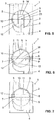
Figur 1 ; und - Fig. 5 bis 7
- Schnittdarstellungen der Siphonanordnung nach
Figur 1 , wobei das Siphonelement an unterschiedlichen Positionen gezeigt wird. - In den Figuren wird eine Siphonanordnung 1 gemäss einer Ausführungsform der vorliegenden Erfindung gezeigt. Die Siphonanordnung 1 umfasst ein Gehäuse 2 mit einem Einlassstutzen 3, einem Auslassstutzen 4 sowie einer zwischen Einlassstutzen 3 und Auslassstutzen 4 angeordneten Siphonaufnahme 5. Weiter umfasst die Siphonanordnung 1 ein in der Siphonaufnahme 5 angeordnetes bzw. gelagertes Siphonelement 6 mit einem Siphonabschnitt 7 sowie einem dem Einlassstutzen 3 zugewandten Eintritt 8 und einem zum Auslassstutzen 4 führenden Austritt 9. Der Siphonabschnitt 7 wirkt als Geruchsverschluss. Wasser wird vom Einlassstutzen 3 über den Eintritt 8 in den Siphonabschnitt 7 geführt, Durchtritt dann den Siphonabschnitt 7 und ist dann über den Austritt 9 zum Auslassstutzen 4 aus dem Siphonabschnitt 7 wegführbar. Das Wasser fliesst durch den Siphonabschnitt 7 hindurch.
- Das Siphonelement 6 ist in der Siphonaufnahme 5 im Gehäuse 2 von einer Gebrauchsposition, so wie es in der
Figur 1 gezeigt wird, in eine Wartungsposition bewegbar gelagert. In der gezeigten Ausführungsform lässt sich das Siphonelement 6 um einen Schwenkachse S verschwenken. Der Verschwenkwinkel kann bis zu 90° betragen. Von der Wartungsposition kann das Siphonelement 6 aus dem Gehäuse 2 entfernt werden. In der gezeigten Ausführungsform wird es entlang der Schwenkachse S aus der Siphonaufnahme 5 herausgezogen. In derFigur 2 wird das entfernte Siphonelement 6 dargestellt. - Von der Schnittdarstellung der
Figur 3 kann gut erkannt werden, wie das Wasser vom Einlassstutzen 3 über den Eintritt 8 in den Siphonabschnitt 7 geführt wird und dann vom Austritt 9 zum Auslassstutzen 4 fliessen kann. In der gezeigten Ausführungsform schliesst sich dem Austritt 9 noch ein Abflussstück 27 an, welches in den Auslassstutzen 4 mündet. Das Abflussstück 27 ist dabei Teil des Siphonelementes 6. - In den
Figuren 5 bis 7 wird gezeigt, dass das Siphonelement 6 derart ausgebildet ist, dass bei einer Bewegung des Siphonelementes 6 das im Siphonabschnitt 7 liegende Wasser mindestens teilweise zum Auslassstutzen 4 fliesst. In derFigur 5 wird das im Siphonabschnitt 7 liegende Wasser mit einer gestrichelten Linie W symbolisiert. In derFigur 5 wird das Siphonelement 6 in der Gebrauchsposition gezeigt. Der Siphonabschnitt 7 ist dabei bis zur Linie W, welche durch den Eintritt 8 und den Austritt 9 verläuft, mit Wasser gefüllt. Wird nun das Siphonelement 6 von der Gebrauchsposition in die Wartungsposition verschwenkt, so kann das im Siphonabschnitt 7 liegende Wasser über den Austritt 9 in Richtung Auslassstutzen 4 abfliessen. Dies wird in derFigur 6 durch den Pfeil P symbolisiert. Das Wasser fliesst also über die Kante mit dem Bezugszeichen 14, welche den Austritt 9 begrenzt, in Richtung des Auslassstutzens 4 ab. Wird nun das Siphonelement 6 noch weiter gedreht, so wie beispielsweise in derFigur 7 gezeigt, kann sämtliches Wasser aus dem Siphonabschnitt 7 ausfliessen. Dies hat den Vorteil, dass im Siphonelement 6 kein oder nur eine möglichst geringe Menge an Restwasser vorhanden ist, wenn das Siphonelement 6 aus dem Gehäuse 2 entfernt wird. - Das Siphonelement 6 ist weiterhin derart ausgebildet, dass allfälliges Restwasser im Siphonabschnitt 7 beim Entfernen des Siphonelementes 6 nicht aus dem Siphonabschnitt 7 ausfliessen kann. Das heisst, der Siphonabschnitt 7 ist als eine Art "Becher" ausgebildet wobei das Wasser dann in diesem "Becher" verbleibt. In der gezeigten Ausführungsform ist der Siphonabschnitt 7 durch eine Wandung 10 begrenzt. Die Wandung 10 umgibt den Siphonabschnitt 7, abgesehen vom Eintritt 8 und vom Austritt 9, im Wesentlichen vollständig. Somit ist der Siphonabschnitt 7 durch die Wandung 10 als umseitig geschlossener Kanal ausgebildet, wodurch der eben genannte "Becher" bereitgestellt werden kann.
- Anhand der
Figur 3 werden nun weitere Merkmale der vorliegenden Ausführungsform genauer erläutert. - In der Gebrauchsposition liegt der Eintritt 8 des Siphonabschnittes 7 im Wesentlichen auf der gleichen Höhe wie der Austritt 9. Der Austritt 9 kann dann bei der Bewegung von der Gebrauchsposition in die Wartungsposition gegen den Auslassstutzen 4 bewegt werden, wobei der Austritt 9 dann tiefer zu liegen kommt als der Eintritt 8. Dies wird in den
Figuren 6 und 7 entsprechend dargestellt. - Der Siphonabschnitt 7 wird durch eine in den Siphonabschnitt 7 ragende Trennwand 11 bereitgestellt. Die Trennwand 11 erstreckt sich in der in
Figur 3 gezeigten Ausführungsform zwischen dem Eintritt 8 und dem Austritt 9. Im unteren Bereich der Trennwand 11 ist ein Durchgang 12 angeordnet. Dieser Durchgang 12 stellt die eigentliche Siphonwirkung bereit. Mit anderen Worten kann auch gesagt werden, dass sich dem Eintritt 8 ein absteigender Siphonabschnitt bis zum Durchgang 12 anschliesst und dass sich dem Durchgang hochsteigender Siphonabschnitt bis zum Austritt 9 anschliesst, wobei die beiden Siphonabschnitte durch die Trennwand 11 voneinander getrennt sind. - Die Siphonaufnahme 5 weist eine zylindrische Lagerwandung 13 auf. In dieser zylindrischen Lagerwandung 13 ist das Siphonelement 6 gelagert. Das Siphonelement 6 weist ebenfalls eine zylindrische Aussenwand 15 auf, welche mindestens einen vollständig umlaufenden Wandabschnitt 19 aufweist. Das Siphonelement 6 steht über die unten beschriebenen Dichtungen mit der Siphonaufnahme 5 in Kontakt.
- Die Lagerwandung 13 der Siphonaufnahme 5 wird vom Einlassstutzen 3 her gesehen durch den Einlassstutzen 3 durchbrochen. Das heisst der Einlassstutzen 3 mündet in die Siphonaufnahme 5 durch die Lagerwandung 13. Darüber hinaus ist die Lagerwandung 13 zum Auslassstutzen 4 hin gesehen mit dem Auslassstutzen 5 durchbrochen. Der Auslassstutzen 4 ragt also ebenfalls durch die Lagerwandung 13 in die Siphonaufnahme 5 ein. Das Wasser tritt dabei durch die entsprechenden Durchbrüche durch die Lagerwandung 13 hindurch.
- Die Lagerwandung 13 begrenzt eine Zugangsöffnung 24, über welche das Siphonelement 6 in die Siphonaufnahme 5 einsetzbar ist.
- Aufgrund der zylindrischen Ausbildung der Lagerwandung 13 und der Aussenwand 15 kann das Siphonelement 6 in der Siphonaufnahme 5, wie oben beschrieben, verschwenkt werden.
- In der
Figur 4 wird gezeigt, dass sich eine Dichtung 16 vollständig um den Eintritt 8 herumerstreckt. Die Dichtung 16 arbeitet dabei mit der besagten Lagerwandung 13 zusammen und dichtet die Mündungsstelle des Einlassstutzens im Bereich des Eintritts 8 vollständig ab. In der gezeigten Ausführungsform ist zudem eine weitere Dichtung 17 angeordnet. - Weiter weist die zylindrische Lagerwandung 13 mindestens einen vollständig umlaufenden Wandabschnitt 18 auf und die Aussenwand 15 des Siphonelementes 6 weist ebenfalls einen vollständig umlaufenden Wandabschnitt 19 auf. Zwischen diesen beiden Wandabschnitten 18, 19 ist mindestens ein vollständig umlaufendes Dichtelement 20, 21 angeordnet. In der gezeigten Ausführungsform ist eine separate Dichtung 21 angeordnet, welche zwischen der Zugangsöffnung 24 und dem Einlassstutzen 3 beziehungsweise im Auslassstutzen 4 liegt. Die Dichtung 20 ist dabei in einer Ausnehmung 25 im Gehäuse im Bereich der Lagerwandung 13 gelagert.
- Darüber hinaus sind weitere Dichtelemente 21 im Bereich der Aussenwand 15 des Siphonelementes angeordnet. In der gezeigten Ausführungsform sind zwei Dichtelemente 21 vorgesehen, welche derart angeordnet sind, dass der Eintritt 8 beziehungsweise der Austritt 9 zwischen diesen beiden umlaufenden Dichtelemente 21 angeordnet ist. Diese Dichtelemente 21 arbeiten dabei mit dem Wandabschnitt 18 der Lagerwandung 13 zusammen.
- Durch das Dichtelement 20 wird sichergestellt, dass kein Wasser zwischen der Trennstelle zwischen dem Siphonelement 6 und der Siphonaufnahme 5 austreten kann. Die Dichtelemente 21 bzw. die beiden Dichtungen 16, 17 sorgen dafür, dass kein Wasser in den Zwischenbereich zwischen dem Siphonelement 6 und der Siphonaufnahme 5 gelangen kann.
- Von der
Figur 3 wie auch von denFiguren 5 bis 7 kann gut erkannt werden, dass der Auslassstutzen 4 relativ zum Einlassstutzen 3 derart angeordnet ist, dass Wasser bei nicht eingesetztem Siphonelement 6 vom Einlassstutzen 3 in den Auslassstutzen 4 fliesst. Der Auslassstutzen 4 weist dabei einen derart grossen Querschnitt auf, dass sich dieser in der Richtung der Vertikalen gesehen bis unter den Einlassstutzen 3 erstreckt. Des Weiteren ist der Auslassstutzen 4 derart angeordnet, dass der Austritt 9 des Siphonelementes bei jeder Stellung des Siphonelementes in den Auslassstutzen 4 mündet. - Das Siphonelement 6 ist über einen Bajonettverschluss 22 im Gehäuse 2 gelagert. Der Bajonettverschluss 2 ist dabei derart angeordnet, dass dieser ausserhalb der wasserführenden Teile liegt. Der Bajonettverschluss 22 weist in der gezeigten Ausführungsform zwei Klemmlaschen 26 auf. Die eine der beiden Klemmlaschen ist dabei anders ausgebildet als die andere der beiden Klemmlaschen, sodass sichergestellt wird, dass das Siphonelement 6 ausschliesslich in der korrekten Lage in das Gehäuse 2 einsetzbar ist.
- Weiter weist das Siphonelement 6 ein von ausserhalb des Gehäuses 2 zugängliches Betätigungselement 23 auf. Das Betätigungselement 23 ist hier also Steg ausgebildet, welcher von einem Benutzer von Hand gut ergriffen werden kann.
BEZUGSZEICHENLISTE 1 Siphonanordnung 26 Klemmlaschen 2 Gehäuse 27 Abflussstück 3 Einlassstutzen W Wasserstand 4 Auslassstutzen S Schwenkachse 5 Siphonaufnahme P Pfeil 6 Siphonelement 7 Siphonabschnitt 8 Eintritt 9 Austritt 10 Wandung 11 Trennwand 12 Durchgang 13 Lagerwandung 14 Kante 15 Aussenwand 16 Dichtung 17 Dichtung 18 Wandabschnitt 19 Wandabschnitt 20 umlaufendes Dichtelement 21 umlaufendes Dichtelement 22 Bajonettverschluss 23 Betätigungselement 24 Zugangsöffnung 25 Ausnehmung
Claims (14)
- Siphonanordnung (1) umfassend
ein Gehäuse (2) mit einem Einlassstutzen (3), einem Auslassstutzen (4) sowie einer zwischen Einlassstutzen (3) und Auslassstutzen (4) angeordneten Siphonaufnahme (5), und
ein in der Siphonaufnahme (5) angeordnetes Siphonelement (6) mit einem Siphonabschnitt (7) sowie einem dem Einlassstutzen (3) zugewandten Eintritt (8) und einem zum Auslassstutzen (4) führenden Austritt (9),
wobei Wasser vom Einlassstutzen (3) über den Eintritt (8) in den Siphonabschnitt (7) und vom Austritt (9) zum Auslassstutzen (4) führbar ist,
wobei das Siphonelement (6) im Gehäuse (2) von einer Gebrauchsposition in eine Wartungsposition bewegbar, insbesondere verschwenkbar, gelagert ist und von der Wartungsposition aus dem Gehäuse (2) entfernbar, insbesondere herausziehbar, ist,
wobei das Siphonelement (6) derart ausgebildet ist, dass bei der Bewegung des Siphonelementes (6) das im Siphonabschnitt (7) liegende Wasser mindestens teilweise zum Auslassstutzen (4) fliesst und
wobei das Siphonelement (6) derart ausgebildet ist, dass allfälliges Restwasser im Siphonabschnitt (7) bei der Bewegung bzw. beim Entfernen des Siphonelementes (6) nicht aus dem Siphonabschnitt (7) ausfliessen kann, wobei die Siphonaufnahme (5) eine zylindrische Lagerwandung (13) für die Lagerung des Siphonelementes (6) aufweist, wobei die Lagerwandung (13) vom Einlassstutzen (3) her gesehen durch den Einlassstutzen (3) durchbrochen ist, dadurch gekennzeichnet, dass die Lagerwandung (13) zum Auslassstutzen (4) hin gesehen mit dem Auslassstutzen (4) durchbrochen ist,
und dass sich mindestens eine Dichtung (16, 17) um den Eintritt (8) vollständig herum erstreckt, welche Dichtung (16, 17) mit der besagten Lagerwandung (13) zusammenarbeitet und sich um die Mündungsstelle des Einlassstutzens (3) vollständig herum erstreckt. - Siphonanordnung (1) nach Anspruch 1, dadurch gekennzeichnet, dass eine Wandung (10) den Siphonabschnitt (7) abgesehen vom Eintritt (8) und vom Ausstritt (9) im Wesentlichen vollständig umgibt.
- Siphonanordnung (1) nach Anspruch 1 oder 2, dadurch gekennzeichnet, dass das Siphonelement (6) um einen Winkel von höchstens 90° verschwenkbar ist.
- Siphonanordnung (1) nach einem der vorhergehenden Ansprüche, dadurch gekennzeichnet, dass der Eintritt (8) in der Gebrauchsposition im Wesentlichen auf der gleichen Höhe oder höher ist wie der Austritt (9) und/oder dass der Austritt (9) bei der Bewegung in die Wartungsposition gegen den Auslassstutzen (4) bewegt wird, wobei der Austritt (9) dann tiefer liegt als der Eintritt (8).
- Siphonanordnung (1) nach einem der vorhergehenden Ansprüche, dadurch gekennzeichnet, dass in dem Siphonabschnitt (7) eine in den Siphonabschnitt (7) ragende Trennwand (11) bereitgestellt wird, wobei sich die Trennwand (11) vorzugsweise zwischen Eintritt (8) und Austritt (9) erstreckt und im unteren Bereich einen Durchgang (12) bereitstellt.
- Siphonanordnung (1) nach einem der vorhergehenden Ansprüche, dadurch gekennzeichnet, dass die Lagerwandung (13) eine Zugangsöffnung (24) begrenzt, über welche das Siphonelement (6) in die Siphonaufnahme (5) einsetzbar ist.
- Siphonanordnung (1) nach einem der bisherigen Ansprüche, dadurch gekennzeichnet, dass die zylindrische Lagerwandung (13) mindestens einen vollständig umlaufenden Wandabschnitt (18) aufweist und dass die Aussenwand (15) des Siphonelements (6) mindestens einen vollständig umlaufenden Wandabschnitt (19) aufweist, wobei zwischen den beiden Wandabschnitten (18, 19) mindestens ein vollständig umlaufendes Dichtelement (20, 21) angeordnet ist.
- Siphonanordnung (1) nach Anspruch 7, dadurch gekennzeichnet, dass zwei beabstandet zueinander liegende umlaufende Dichtelemente (21) angeordnet sind, wobei zwischen den Dichtelementen (21) der Eintritt bzw. der Austritt liegen.
- Siphonanordnung (1) nach 8, dadurch gekennzeichnet, dass Teile der Dichtung (16, 17) durch Teile des Dichtelementes (20, 21) bereitgestellt werden.
- Siphonanordnung (1) nach einem der vorhergehenden Ansprüche, dadurch gekennzeichnet, dass der Auslassstutzen (4) relativ zum Einlassstutzen (3) derart anordnet ist, dass Wasser bei nicht eingesetztem Siphonelement (6) vom Einlassstutzen (3) in den Auslassstutzen (4) fliesst.
- Siphonanordnung (1) nach einem der vorhergehenden Ansprüche, dadurch gekennzeichnet, dass der Auslassstutzen (4) derart angeordnet ist, dass der Austritt (9) des Siphonabschnittes (7) bei jeder Stellung des Siphonelementes (6) in den Auslassstutzen (4) mündet.
- Siphonanordnung (1) nach einem der vorhergehenden Ansprüche, dadurch gekennzeichnet, dass das Siphonelement (6) über einen Bajonettverschluss (22) oder selbsthemmend im Gehäuse (2) gelagert ist.
- Siphonanordnung (1) nach Anspruch 12, dadurch gekennzeichnet, dass der Bajonettverschluss (22) derart ausgebildet ist, dass das Siphonelement ausschliesslich in der korrekten Lage in das Gehäuse einsetzbar ist.
- Siphonanordnung (1) nach einem der vorhergehenden Ansprüche, dadurch gekennzeichnet, dass das Siphonelement (6) ein von ausserhalb des Gehäuses (2) zugängliches Betätigungselement (23) aufweist.
Priority Applications (6)
| Application Number | Priority Date | Filing Date | Title |
|---|---|---|---|
| EP16175445.2A EP3260607B1 (de) | 2016-06-21 | 2016-06-21 | Siphon |
| EP17167952.5A EP3260608B1 (de) | 2016-06-21 | 2017-04-25 | Siphonanordnung |
| PCT/EP2017/079294 WO2018197026A1 (de) | 2016-06-21 | 2017-11-15 | Siphon |
| AU2017411393A AU2017411393B2 (en) | 2016-06-21 | 2017-11-15 | Siphon |
| CN201780089954.6A CN110546333B (zh) | 2016-06-21 | 2017-11-15 | 虹吸管 |
| US16/607,938 US11280076B2 (en) | 2016-06-21 | 2017-11-15 | Siphon |
Applications Claiming Priority (1)
| Application Number | Priority Date | Filing Date | Title |
|---|---|---|---|
| EP16175445.2A EP3260607B1 (de) | 2016-06-21 | 2016-06-21 | Siphon |
Publications (2)
| Publication Number | Publication Date |
|---|---|
| EP3260607A1 EP3260607A1 (de) | 2017-12-27 |
| EP3260607B1 true EP3260607B1 (de) | 2020-01-29 |
Family
ID=56148263
Family Applications (2)
| Application Number | Title | Priority Date | Filing Date |
|---|---|---|---|
| EP16175445.2A Active EP3260607B1 (de) | 2016-06-21 | 2016-06-21 | Siphon |
| EP17167952.5A Active EP3260608B1 (de) | 2016-06-21 | 2017-04-25 | Siphonanordnung |
Family Applications After (1)
| Application Number | Title | Priority Date | Filing Date |
|---|---|---|---|
| EP17167952.5A Active EP3260608B1 (de) | 2016-06-21 | 2017-04-25 | Siphonanordnung |
Country Status (5)
| Country | Link |
|---|---|
| US (1) | US11280076B2 (de) |
| EP (2) | EP3260607B1 (de) |
| CN (1) | CN110546333B (de) |
| AU (1) | AU2017411393B2 (de) |
| WO (1) | WO2018197026A1 (de) |
Families Citing this family (1)
| Publication number | Priority date | Publication date | Assignee | Title |
|---|---|---|---|---|
| EP3775416B1 (de) * | 2018-03-29 | 2023-04-26 | Geberit International AG | Siphon |
Family Cites Families (21)
| Publication number | Priority date | Publication date | Assignee | Title |
|---|---|---|---|---|
| US427546A (en) * | 1890-05-13 | Albert claude bowerman | ||
| US784849A (en) * | 1904-07-21 | 1905-03-14 | Arthur L Fuqua | Trap. |
| US919701A (en) * | 1909-01-09 | 1909-04-27 | John J Donovan | Trap. |
| US1176806A (en) | 1915-10-26 | 1916-03-28 | Henry Clayton Wood | Combination dishstone, gully-trap, and drain connection for use in sanitary work. |
| US1284165A (en) * | 1918-03-28 | 1918-11-05 | Louis Weimerskirch | Trap. |
| US3346887A (en) * | 1965-02-11 | 1967-10-17 | Anaconda American Brass Co | Sanitary drain system, method, and fittings therefor |
| CH569851A5 (de) * | 1973-03-02 | 1975-11-28 | Innorec Sa | |
| US4523740A (en) * | 1981-10-01 | 1985-06-18 | Hayward Industries | Rotatable unitary ball valve |
| DE3725076A1 (de) * | 1987-07-29 | 1989-02-09 | Norbert Scherer | Schmutzwasserablauf mit ausziehbarem geruchverschluss |
| AT402415B (de) * | 1994-11-15 | 1997-05-26 | Hutterer & Lechner Kg | Unterputzsifon |
| DE50203264D1 (de) | 2002-02-11 | 2005-07-07 | Geberit Technik Ag | Ablaufarmatur für eine Sanitärvorrichtung, insbesondere Urinal |
| DE20302386U1 (de) | 2003-02-14 | 2004-06-24 | Franz Viegener Ii Gmbh & Co. Kg | Ablauf |
| WO2009094675A1 (en) * | 2008-01-23 | 2009-07-30 | Pieter Albertus Reinecke | A plumbing connection hub |
| DE202009004764U1 (de) | 2009-04-30 | 2010-09-16 | Hettich Holding Gmbh & Co. Ohg | Siphon und Möbel |
| AT508270B1 (de) | 2009-05-25 | 2011-03-15 | Hl Hutterer & Lechner Gmbh | Siphon |
| CN202031147U (zh) | 2011-04-23 | 2011-11-09 | 广东三凌塑料管材有限公司 | 一种存水弯 |
| FR2983556B1 (fr) | 2011-12-06 | 2013-12-13 | Hutchinson | Organe de verrouillage d'un dispositif de raccordement pour transfert de fluide, ce dispositif et son procede de verrouillage. |
| US9518665B2 (en) * | 2013-11-14 | 2016-12-13 | Hantemp Corporation | Ball valve for cold fluids |
| CN204356864U (zh) | 2014-12-15 | 2015-05-27 | 蒋祥志 | 厨卫下水防臭接头管 |
| CN205062937U (zh) | 2015-11-03 | 2016-03-02 | 黄瑞洛 | 可调节式水槽排水管道 |
| AT15113U1 (de) * | 2015-11-16 | 2017-01-15 | Hl Hutterer & Lechner Gmbh | Siphon mit getrennten Kammern |
-
2016
- 2016-06-21 EP EP16175445.2A patent/EP3260607B1/de active Active
-
2017
- 2017-04-25 EP EP17167952.5A patent/EP3260608B1/de active Active
- 2017-11-15 WO PCT/EP2017/079294 patent/WO2018197026A1/de active Application Filing
- 2017-11-15 CN CN201780089954.6A patent/CN110546333B/zh active Active
- 2017-11-15 US US16/607,938 patent/US11280076B2/en active Active
- 2017-11-15 AU AU2017411393A patent/AU2017411393B2/en active Active
Non-Patent Citations (1)
| Title |
|---|
| None * |
Also Published As
| Publication number | Publication date |
|---|---|
| US20200063414A1 (en) | 2020-02-27 |
| EP3260608A1 (de) | 2017-12-27 |
| CN110546333B (zh) | 2021-07-16 |
| WO2018197026A1 (de) | 2018-11-01 |
| EP3260608B1 (de) | 2019-08-07 |
| AU2017411393A1 (en) | 2019-10-24 |
| US11280076B2 (en) | 2022-03-22 |
| AU2017411393B2 (en) | 2023-04-20 |
| CN110546333A (zh) | 2019-12-06 |
| EP3260607A1 (de) | 2017-12-27 |
Similar Documents
| Publication | Publication Date | Title |
|---|---|---|
| EP2840191B1 (de) | Geruchsverschlussvorrichtung | |
| EP2045403B1 (de) | Ablaufgarnitur mit integriertem Überlauf | |
| EP2363543B1 (de) | Ablaufgarnitur mit Reinigungsöffnung | |
| EP3773099B1 (de) | Waschtisch | |
| EP3835500B1 (de) | Ablaufanordnung | |
| EP1775395B1 (de) | Ablaufarmatur für sanitäre Anlagen | |
| EP3260607B1 (de) | Siphon | |
| EP3455421B1 (de) | Ablaufventil für einen spülkasten und spülkasten mit ablaufventil | |
| EP2746474A1 (de) | Spülvorrichtung mit Geruchsabsaugung | |
| EP0726368A1 (de) | Ablaufventil für einen Spülkasten | |
| EP0185109B1 (de) | Geruchsverschluss | |
| EP1184520B1 (de) | Bodenablauf mit herausnehmbarem Geruchsverschlusselement | |
| DE102004062634B3 (de) | Überlaufgarnitur für eine Sanitärwanne | |
| DE102008023894A1 (de) | Badewannen-Bodenzufluss mit Niveautrennung des zulaufenden Mischwassers und des ablaufenden Wannenwassers, gegen Rücksaugen abgesichert mit einer externen, handelsüblichen Sicherungseinrichtung, die mindestens 150 mm über dem oberen Wannenrand ist | |
| DE19706620B4 (de) | Abtrenneinrichtung für Regenwasser | |
| DE10204683B4 (de) | Becken | |
| DE102016100338A1 (de) | Überlauf für ein Becken, insbesondere Spülenbecken | |
| EP3775416B1 (de) | Siphon | |
| EP3647505A1 (de) | Spülwasserdüsenanordnung | |
| DE202014104522U1 (de) | Ablaufgarnitur für eine Spüle, insbesondere Küchenspüle | |
| EP3647504B1 (de) | Sanitärartikelanordnung | |
| EP1614816B1 (de) | Überlauf- und Ablaufgarnitur für sanitäre Apparate | |
| DE10148959A1 (de) | Urinalvorrichtung, die an einer Wand befestigbar ist | |
| DE202015107000U1 (de) | Ablaufsystem | |
| EP4063574A1 (de) | Waschtischanordnung |
Legal Events
| Date | Code | Title | Description |
|---|---|---|---|
| PUAI | Public reference made under article 153(3) epc to a published international application that has entered the european phase |
Free format text: ORIGINAL CODE: 0009012 |
|
| STAA | Information on the status of an ep patent application or granted ep patent |
Free format text: STATUS: THE APPLICATION HAS BEEN PUBLISHED |
|
| AK | Designated contracting states |
Kind code of ref document: A1 Designated state(s): AL AT BE BG CH CY CZ DE DK EE ES FI FR GB GR HR HU IE IS IT LI LT LU LV MC MK MT NL NO PL PT RO RS SE SI SK SM TR |
|
| AX | Request for extension of the european patent |
Extension state: BA ME |
|
| STAA | Information on the status of an ep patent application or granted ep patent |
Free format text: STATUS: REQUEST FOR EXAMINATION WAS MADE |
|
| 17P | Request for examination filed |
Effective date: 20180515 |
|
| RBV | Designated contracting states (corrected) |
Designated state(s): AL AT BE BG CH CY CZ DE DK EE ES FI FR GB GR HR HU IE IS IT LI LT LU LV MC MK MT NL NO PL PT RO RS SE SI SK SM TR |
|
| REG | Reference to a national code |
Ref country code: DE Ref legal event code: R079 Ref document number: 502016008505 Country of ref document: DE Free format text: PREVIOUS MAIN CLASS: E03C0001284000 Ipc: E03C0001290000 |
|
| RIC1 | Information provided on ipc code assigned before grant |
Ipc: E03C 1/29 20060101AFI20190711BHEP Ipc: E03C 1/284 20060101ALI20190711BHEP |
|
| GRAP | Despatch of communication of intention to grant a patent |
Free format text: ORIGINAL CODE: EPIDOSNIGR1 |
|
| STAA | Information on the status of an ep patent application or granted ep patent |
Free format text: STATUS: GRANT OF PATENT IS INTENDED |
|
| INTG | Intention to grant announced |
Effective date: 20190821 |
|
| GRAS | Grant fee paid |
Free format text: ORIGINAL CODE: EPIDOSNIGR3 |
|
| GRAA | (expected) grant |
Free format text: ORIGINAL CODE: 0009210 |
|
| STAA | Information on the status of an ep patent application or granted ep patent |
Free format text: STATUS: THE PATENT HAS BEEN GRANTED |
|
| AK | Designated contracting states |
Kind code of ref document: B1 Designated state(s): AL AT BE BG CH CY CZ DE DK EE ES FI FR GB GR HR HU IE IS IT LI LT LU LV MC MK MT NL NO PL PT RO RS SE SI SK SM TR |
|
| REG | Reference to a national code |
Ref country code: GB Ref legal event code: FG4D Free format text: NOT ENGLISH |
|
| REG | Reference to a national code |
Ref country code: CH Ref legal event code: EP |
|
| REG | Reference to a national code |
Ref country code: AT Ref legal event code: REF Ref document number: 1228582 Country of ref document: AT Kind code of ref document: T Effective date: 20200215 |
|
| REG | Reference to a national code |
Ref country code: IE Ref legal event code: FG4D Free format text: LANGUAGE OF EP DOCUMENT: GERMAN |
|
| REG | Reference to a national code |
Ref country code: DE Ref legal event code: R096 Ref document number: 502016008505 Country of ref document: DE |
|
| REG | Reference to a national code |
Ref country code: CH Ref legal event code: NV Representative=s name: ISLER AND PEDRAZZINI AG, CH |
|
| REG | Reference to a national code |
Ref country code: NL Ref legal event code: MP Effective date: 20200129 |
|
| PG25 | Lapsed in a contracting state [announced via postgrant information from national office to epo] |
Ref country code: PT Free format text: LAPSE BECAUSE OF FAILURE TO SUBMIT A TRANSLATION OF THE DESCRIPTION OR TO PAY THE FEE WITHIN THE PRESCRIBED TIME-LIMIT Effective date: 20200621 Ref country code: FI Free format text: LAPSE BECAUSE OF FAILURE TO SUBMIT A TRANSLATION OF THE DESCRIPTION OR TO PAY THE FEE WITHIN THE PRESCRIBED TIME-LIMIT Effective date: 20200129 Ref country code: RS Free format text: LAPSE BECAUSE OF FAILURE TO SUBMIT A TRANSLATION OF THE DESCRIPTION OR TO PAY THE FEE WITHIN THE PRESCRIBED TIME-LIMIT Effective date: 20200129 Ref country code: NO Free format text: LAPSE BECAUSE OF FAILURE TO SUBMIT A TRANSLATION OF THE DESCRIPTION OR TO PAY THE FEE WITHIN THE PRESCRIBED TIME-LIMIT Effective date: 20200429 |
|
| REG | Reference to a national code |
Ref country code: LT Ref legal event code: MG4D |
|
| PG25 | Lapsed in a contracting state [announced via postgrant information from national office to epo] |
Ref country code: IS Free format text: LAPSE BECAUSE OF FAILURE TO SUBMIT A TRANSLATION OF THE DESCRIPTION OR TO PAY THE FEE WITHIN THE PRESCRIBED TIME-LIMIT Effective date: 20200529 Ref country code: GR Free format text: LAPSE BECAUSE OF FAILURE TO SUBMIT A TRANSLATION OF THE DESCRIPTION OR TO PAY THE FEE WITHIN THE PRESCRIBED TIME-LIMIT Effective date: 20200430 Ref country code: BG Free format text: LAPSE BECAUSE OF FAILURE TO SUBMIT A TRANSLATION OF THE DESCRIPTION OR TO PAY THE FEE WITHIN THE PRESCRIBED TIME-LIMIT Effective date: 20200429 Ref country code: HR Free format text: LAPSE BECAUSE OF FAILURE TO SUBMIT A TRANSLATION OF THE DESCRIPTION OR TO PAY THE FEE WITHIN THE PRESCRIBED TIME-LIMIT Effective date: 20200129 Ref country code: LV Free format text: LAPSE BECAUSE OF FAILURE TO SUBMIT A TRANSLATION OF THE DESCRIPTION OR TO PAY THE FEE WITHIN THE PRESCRIBED TIME-LIMIT Effective date: 20200129 Ref country code: SE Free format text: LAPSE BECAUSE OF FAILURE TO SUBMIT A TRANSLATION OF THE DESCRIPTION OR TO PAY THE FEE WITHIN THE PRESCRIBED TIME-LIMIT Effective date: 20200129 |
|
| PG25 | Lapsed in a contracting state [announced via postgrant information from national office to epo] |
Ref country code: NL Free format text: LAPSE BECAUSE OF FAILURE TO SUBMIT A TRANSLATION OF THE DESCRIPTION OR TO PAY THE FEE WITHIN THE PRESCRIBED TIME-LIMIT Effective date: 20200129 |
|
| PG25 | Lapsed in a contracting state [announced via postgrant information from national office to epo] |
Ref country code: DK Free format text: LAPSE BECAUSE OF FAILURE TO SUBMIT A TRANSLATION OF THE DESCRIPTION OR TO PAY THE FEE WITHIN THE PRESCRIBED TIME-LIMIT Effective date: 20200129 Ref country code: EE Free format text: LAPSE BECAUSE OF FAILURE TO SUBMIT A TRANSLATION OF THE DESCRIPTION OR TO PAY THE FEE WITHIN THE PRESCRIBED TIME-LIMIT Effective date: 20200129 Ref country code: SM Free format text: LAPSE BECAUSE OF FAILURE TO SUBMIT A TRANSLATION OF THE DESCRIPTION OR TO PAY THE FEE WITHIN THE PRESCRIBED TIME-LIMIT Effective date: 20200129 Ref country code: SK Free format text: LAPSE BECAUSE OF FAILURE TO SUBMIT A TRANSLATION OF THE DESCRIPTION OR TO PAY THE FEE WITHIN THE PRESCRIBED TIME-LIMIT Effective date: 20200129 Ref country code: ES Free format text: LAPSE BECAUSE OF FAILURE TO SUBMIT A TRANSLATION OF THE DESCRIPTION OR TO PAY THE FEE WITHIN THE PRESCRIBED TIME-LIMIT Effective date: 20200129 Ref country code: LT Free format text: LAPSE BECAUSE OF FAILURE TO SUBMIT A TRANSLATION OF THE DESCRIPTION OR TO PAY THE FEE WITHIN THE PRESCRIBED TIME-LIMIT Effective date: 20200129 Ref country code: RO Free format text: LAPSE BECAUSE OF FAILURE TO SUBMIT A TRANSLATION OF THE DESCRIPTION OR TO PAY THE FEE WITHIN THE PRESCRIBED TIME-LIMIT Effective date: 20200129 Ref country code: CZ Free format text: LAPSE BECAUSE OF FAILURE TO SUBMIT A TRANSLATION OF THE DESCRIPTION OR TO PAY THE FEE WITHIN THE PRESCRIBED TIME-LIMIT Effective date: 20200129 |
|
| REG | Reference to a national code |
Ref country code: DE Ref legal event code: R097 Ref document number: 502016008505 Country of ref document: DE |
|
| PLBE | No opposition filed within time limit |
Free format text: ORIGINAL CODE: 0009261 |
|
| STAA | Information on the status of an ep patent application or granted ep patent |
Free format text: STATUS: NO OPPOSITION FILED WITHIN TIME LIMIT |
|
| 26N | No opposition filed |
Effective date: 20201030 |
|
| PG25 | Lapsed in a contracting state [announced via postgrant information from national office to epo] |
Ref country code: MC Free format text: LAPSE BECAUSE OF FAILURE TO SUBMIT A TRANSLATION OF THE DESCRIPTION OR TO PAY THE FEE WITHIN THE PRESCRIBED TIME-LIMIT Effective date: 20200129 |
|
| PG25 | Lapsed in a contracting state [announced via postgrant information from national office to epo] |
Ref country code: PL Free format text: LAPSE BECAUSE OF FAILURE TO SUBMIT A TRANSLATION OF THE DESCRIPTION OR TO PAY THE FEE WITHIN THE PRESCRIBED TIME-LIMIT Effective date: 20200129 Ref country code: SI Free format text: LAPSE BECAUSE OF FAILURE TO SUBMIT A TRANSLATION OF THE DESCRIPTION OR TO PAY THE FEE WITHIN THE PRESCRIBED TIME-LIMIT Effective date: 20200129 |
|
| PG25 | Lapsed in a contracting state [announced via postgrant information from national office to epo] |
Ref country code: LU Free format text: LAPSE BECAUSE OF NON-PAYMENT OF DUE FEES Effective date: 20200621 |
|
| PG25 | Lapsed in a contracting state [announced via postgrant information from national office to epo] |
Ref country code: IE Free format text: LAPSE BECAUSE OF NON-PAYMENT OF DUE FEES Effective date: 20200621 |
|
| PG25 | Lapsed in a contracting state [announced via postgrant information from national office to epo] |
Ref country code: TR Free format text: LAPSE BECAUSE OF FAILURE TO SUBMIT A TRANSLATION OF THE DESCRIPTION OR TO PAY THE FEE WITHIN THE PRESCRIBED TIME-LIMIT Effective date: 20200129 Ref country code: MT Free format text: LAPSE BECAUSE OF FAILURE TO SUBMIT A TRANSLATION OF THE DESCRIPTION OR TO PAY THE FEE WITHIN THE PRESCRIBED TIME-LIMIT Effective date: 20200129 Ref country code: CY Free format text: LAPSE BECAUSE OF FAILURE TO SUBMIT A TRANSLATION OF THE DESCRIPTION OR TO PAY THE FEE WITHIN THE PRESCRIBED TIME-LIMIT Effective date: 20200129 |
|
| PG25 | Lapsed in a contracting state [announced via postgrant information from national office to epo] |
Ref country code: MK Free format text: LAPSE BECAUSE OF FAILURE TO SUBMIT A TRANSLATION OF THE DESCRIPTION OR TO PAY THE FEE WITHIN THE PRESCRIBED TIME-LIMIT Effective date: 20200129 Ref country code: AL Free format text: LAPSE BECAUSE OF FAILURE TO SUBMIT A TRANSLATION OF THE DESCRIPTION OR TO PAY THE FEE WITHIN THE PRESCRIBED TIME-LIMIT Effective date: 20200129 |
|
| P01 | Opt-out of the competence of the unified patent court (upc) registered |
Effective date: 20230516 |
|
| PGFP | Annual fee paid to national office [announced via postgrant information from national office to epo] |
Ref country code: IT Payment date: 20230621 Year of fee payment: 8 Ref country code: CH Payment date: 20230702 Year of fee payment: 8 |
|
| PGFP | Annual fee paid to national office [announced via postgrant information from national office to epo] |
Ref country code: GB Payment date: 20240621 Year of fee payment: 9 |
|
| PGFP | Annual fee paid to national office [announced via postgrant information from national office to epo] |
Ref country code: DE Payment date: 20240619 Year of fee payment: 9 |
|
| PGFP | Annual fee paid to national office [announced via postgrant information from national office to epo] |
Ref country code: AT Payment date: 20240620 Year of fee payment: 9 |
|
| PGFP | Annual fee paid to national office [announced via postgrant information from national office to epo] |
Ref country code: FR Payment date: 20240628 Year of fee payment: 9 |
|
| REG | Reference to a national code |
Ref country code: BE Ref legal event code: PD Owner name: GEBERIT HOLDING AG; CH Free format text: DETAILS ASSIGNMENT: CHANGE OF OWNER(S), MERGE; FORMER OWNER NAME: GEBERIT INTERNATIONAL AG Effective date: 20240528 Ref country code: BE Ref legal event code: HC Owner name: GEBERIT INTERNATIONAL AG; CH Free format text: DETAILS ASSIGNMENT: CHANGE OF OWNER(S), CHANGE OF OWNER(S) NAME; FORMER OWNER NAME: GEBERIT HOLDING AG Effective date: 20240528 |
|
| PGFP | Annual fee paid to national office [announced via postgrant information from national office to epo] |
Ref country code: BE Payment date: 20240619 Year of fee payment: 9 |