EP3259999B1 - Acheminement d'articles en forme de tige de l'industrie de traitement du tabac - Google Patents
Acheminement d'articles en forme de tige de l'industrie de traitement du tabac Download PDFInfo
- Publication number
- EP3259999B1 EP3259999B1 EP17181352.0A EP17181352A EP3259999B1 EP 3259999 B1 EP3259999 B1 EP 3259999B1 EP 17181352 A EP17181352 A EP 17181352A EP 3259999 B1 EP3259999 B1 EP 3259999B1
- Authority
- EP
- European Patent Office
- Prior art keywords
- rod
- shaped articles
- conveying
- drum
- type
- Prior art date
- Legal status (The legal status is an assumption and is not a legal conclusion. Google has not performed a legal analysis and makes no representation as to the accuracy of the status listed.)
- Active
Links
- 238000012545 processing Methods 0.000 title claims description 32
- 241000208125 Nicotiana Species 0.000 title description 51
- 235000002637 Nicotiana tabacum Nutrition 0.000 title description 51
- 235000019504 cigarettes Nutrition 0.000 claims description 58
- 238000012546 transfer Methods 0.000 claims description 49
- 230000008859 change Effects 0.000 claims description 24
- 238000000034 method Methods 0.000 claims description 20
- 230000000717 retained effect Effects 0.000 claims description 6
- 238000012360 testing method Methods 0.000 description 22
- 238000004519 manufacturing process Methods 0.000 description 20
- 238000005520 cutting process Methods 0.000 description 13
- 238000005096 rolling process Methods 0.000 description 9
- 238000011161 development Methods 0.000 description 6
- 210000000056 organ Anatomy 0.000 description 3
- 230000000391 smoking effect Effects 0.000 description 3
- 230000006978 adaptation Effects 0.000 description 2
- 238000006243 chemical reaction Methods 0.000 description 2
- 239000003795 chemical substances by application Substances 0.000 description 2
- 239000011248 coating agent Substances 0.000 description 2
- 238000000576 coating method Methods 0.000 description 2
- 238000006073 displacement reaction Methods 0.000 description 2
- 230000007246 mechanism Effects 0.000 description 2
- 238000000465 moulding Methods 0.000 description 2
- 238000003892 spreading Methods 0.000 description 2
- 230000007480 spreading Effects 0.000 description 2
- 230000008901 benefit Effects 0.000 description 1
- 230000000295 complement effect Effects 0.000 description 1
- 230000006735 deficit Effects 0.000 description 1
- 238000013461 design Methods 0.000 description 1
- 210000003746 feather Anatomy 0.000 description 1
- 238000003780 insertion Methods 0.000 description 1
- 230000037431 insertion Effects 0.000 description 1
- 238000007689 inspection Methods 0.000 description 1
- 239000000463 material Substances 0.000 description 1
- 230000002093 peripheral effect Effects 0.000 description 1
- 230000008569 process Effects 0.000 description 1
- 230000001737 promoting effect Effects 0.000 description 1
- 238000005070 sampling Methods 0.000 description 1
- 238000003860 storage Methods 0.000 description 1
- XXUZFRDUEGQHOV-UHFFFAOYSA-J strontium ranelate Chemical compound [Sr+2].[Sr+2].[O-]C(=O)CN(CC([O-])=O)C=1SC(C([O-])=O)=C(CC([O-])=O)C=1C#N XXUZFRDUEGQHOV-UHFFFAOYSA-J 0.000 description 1
- 238000009423 ventilation Methods 0.000 description 1
Images


Classifications
-
- B—PERFORMING OPERATIONS; TRANSPORTING
- B65—CONVEYING; PACKING; STORING; HANDLING THIN OR FILAMENTARY MATERIAL
- B65G—TRANSPORT OR STORAGE DEVICES, e.g. CONVEYORS FOR LOADING OR TIPPING, SHOP CONVEYOR SYSTEMS OR PNEUMATIC TUBE CONVEYORS
- B65G47/00—Article or material-handling devices associated with conveyors; Methods employing such devices
- B65G47/74—Feeding, transfer, or discharging devices of particular kinds or types
- B65G47/84—Star-shaped wheels or devices having endless travelling belts or chains, the wheels or devices being equipped with article-engaging elements
- B65G47/846—Star-shaped wheels or wheels equipped with article-engaging elements
- B65G47/848—Star-shaped wheels or wheels equipped with article-engaging elements the article-engaging elements being suction or magnetic means
-
- A—HUMAN NECESSITIES
- A24—TOBACCO; CIGARS; CIGARETTES; SIMULATED SMOKING DEVICES; SMOKERS' REQUISITES
- A24C—MACHINES FOR MAKING CIGARS OR CIGARETTES
- A24C5/00—Making cigarettes; Making tipping materials for, or attaching filters or mouthpieces to, cigars or cigarettes
- A24C5/32—Separating, ordering, counting or examining cigarettes; Regulating the feeding of tobacco according to rod or cigarette condition
- A24C5/322—Transporting cigarettes during manufacturing
- A24C5/327—Construction details of the cigarette transport drum
-
- A—HUMAN NECESSITIES
- A24—TOBACCO; CIGARS; CIGARETTES; SIMULATED SMOKING DEVICES; SMOKERS' REQUISITES
- A24C—MACHINES FOR MAKING CIGARS OR CIGARETTES
- A24C5/00—Making cigarettes; Making tipping materials for, or attaching filters or mouthpieces to, cigars or cigarettes
- A24C5/47—Attaching filters or mouthpieces to cigars or cigarettes, e.g. inserting filters into cigarettes or their mouthpieces
- A24C5/478—Transport means for filter- or cigarette-rods in view of their assembling
Definitions
- the invention relates to a method for conveying rod-shaped articles, in particular filter cigarettes or their rod-shaped components, the rod-shaped articles being conveyed transversely axially in receiving troughs of conveyor drums with rotation of the conveyor drums.
- the invention also relates to an arrangement for conveying rod-shaped articles, in particular filter cigarettes or their components, with several conveying drums rotating or rotatable about their own axis of rotation for the transverse axial conveying of rod-shaped articles in the tobacco processing industry.
- the invention also relates to a machine in the tobacco processing industry, in particular a filter attachment machine, for the production of rod-shaped articles in the tobacco processing industry, especially filter cigarettes.
- conveyor drums are used to transport cigarettes, filter pieces or their components.
- components of the cigarettes and filter rods also includes sections of paper and the like made of flat and / or web-shaped material, e.g. Sections and / or webs of cigarette paper, filter paper or tipping paper for connecting tobacco pieces with filter plugs.
- conveying of the aforementioned objects during the production of cigarettes, filters and filter cigarettes is generally carried out in modern production machines in the tobacco processing industry by means of conveyor drums, the outer surface of which is used for conveying rod-shaped objects as rod-shaped components (cigarettes, filter rods or filter stoppers, filter cigarettes) with hollows for Pick up the items are provided.
- rod-shaped objects as rod-shaped components (cigarettes, filter rods or filter stoppers, filter cigarettes) with hollows for Pick up the items are provided.
- conveying drums are provided, the outer surfaces of which are essentially smooth.
- these objects of the tobacco-processing industry are held on the conveyor drums by suction air, which rests on corresponding channels, mostly bores. These channels are generally arranged in rows, the lengths of which correspond to the dimensions of the objects to be transported transversely to the direction of transport.
- rod-shaped articles such as tobacco sticks or filter plugs or filter stems
- Articles such as tobacco sticks or filter plugs or filter rods are conveyed transversely axially in receiving troughs of the conveyor drum.
- the receiving troughs are arranged at predetermined spacings on the peripheral surface of the conveyor drum.
- the division spacing is understood to mean the transverse axial spacing of the receiving troughs.
- the distance is from the trough center of the receiving trough to the following trough center of the adjacent receiving trough of the trough conveyor transporting the rod-shaped smoking article (groups) on the surface or from trough bottom to trough bottom with e.g. a prism-shaped receiving recess measured.
- the pitch in a drum conveyor also known as a conveyor drum, is the transverse axial distance or the length of the (circular) arc between (adjacent) trough centers on the circular line on which the trough centers or trough center axes of the troughs are arranged.
- a conveyor drum of the tobacco processing industry wherein two different types of receiving troughs are provided for the rod-shaped articles.
- Each type of receiving recess is adapted to at least one predetermined geometric parameter, in particular diameter, of the rod-shaped article to be conveyed, so that two different articles can be conveyed on the conveyor drum, each with different geometric parameters.
- EP 1 702 523 A1 a method for the production of filter cigarettes, wherein before a filter plug is inserted between longitudinally axially spaced pairs of tobacco rods, the tobacco rods are conveyed with a transverse axial distance which is less than the length of the connecting leaflet attached subsequently.
- the smoking article groups formed are fed to a coating device as articles of a first group and a second group, so that the article flow formed is divided into two article flows.
- the transverse axial distance between the smoking article groups in each group is increased.
- the object of the present invention is to enable the conveyance of rod-shaped articles on a machine in the tobacco processing industry, for example a filter attachment machine, for a quick change in diameter format in a simple manner, whereby the design effort should be kept as low as possible .
- This object is achieved by a method for conveying rod-shaped articles of the tobacco-processing industry, in particular filter cigarettes or their rod-shaped components, the rod-shaped articles being conveyed transversely axially in receiving troughs by conveyor drums while the conveyor drums rotate, each rotating or rotatable about its own axis of rotation Conveyor drums are arranged one behind the other in the transverse direction of conveyance of the rod-shaped articles, the bar-shaped articles arranged in at least one row transversely axially one behind the other being transferred from a conveyor drum to a subsequent conveyor drum, the method being further developed in that when the rod-shaped articles to be conveyed change from bar-shaped Articles of a first type with a predetermined diameter to rod-shaped articles of a second type with a predetermined diameter, the The diameter of the article of the first type and the diameter of the article of the second type differ from one another, the pitch of the receiving troughs of at least one conveyor drum is changed depending on the rod-shaped articles to be conveyed such that
- the invention is based on the idea that in a machine in the tobacco processing industry, in which the rod-shaped articles are conveyed transversely axially using conveyor drums, without exchanging the conveyor drums and without changing the position of the drums on the filter attachment machine, the conveyor drums are set such that Regardless of the diameter of the conveyed or to be conveyed rod-shaped articles, the central longitudinal axes of the conveyed rod-shaped articles are always conveyed on the same circular arc of the central longitudinal axes of the articles, the radius of the circular arc for the central longitudinal axes of the rod-shaped articles to be conveyed being kept constant on the respective conveyor drum.
- the receiving troughs By changing the pitch of the trough center axes the receiving troughs, which is changed depending on the diameter of the rod-shaped article to be conveyed or conveyed during a product or format change, ensures that the circular arcs of the central longitudinal axes of the rod-shaped articles of the first type and the central longitudinal axes of the rod-shaped articles of the second type are the same, have approximately constant radius.
- the spacing of the receiving troughs on at least one conveyor drum is changed and adapted for conveying the articles of the second type.
- Rod-shaped articles of the tobacco processing industry in the context of the invention are understood to mean rod-shaped objects such as cigarettes, filter rods or filter plugs or their (rod-shaped) components.
- rod-shaped article of a first type is understood to mean a certain type of rod-shaped articles to be conveyed in the tobacco processing industry, which have a predetermined diameter and are conveyed transversely axially, for example, on a filter attachment machine.
- rod-shaped article of a second type is understood to mean a certain type of rod-shaped articles to be conveyed in the tobacco processing industry, which have a predetermined diameter and e.g. be conveyed transversely axially on a filter attachment machine and differ in diameter from the rod-shaped articles of the first type.
- One advantage of the invention is that several rod-shaped articles of different diameters are conveyed and produced on a filter attachment machine without replacing all of the conveyor drums, which means that conversion measures when changing from rod-shaped articles of a first type to be conveyed to bar-shaped articles of a second type are considerably reduced, since costly change of all conveying organs is avoided or not carried out.
- the spacing between the receiving troughs of the conveying drums is changed or adapted.
- At least one contact surface of a receiving trough is understood to be a surface of a receiving trough on which the rod-shaped articles to be conveyed (of the first type and the second type) rest on the conveyor drum during conveyance, whereby the contact surface is in touching contact with the received rod-shaped articles.
- the distance between the respective contact surface of the receiving troughs of the conveyor drum and the axis of rotation of the conveyor drums when receiving rod-shaped articles of the first type differs from the distance between the same contact surfaces of the same receiving trough of the conveyor drum and the axis of rotation of the conveyor drums when receiving articles of the second type
- the non-exchangeable receiving troughs of the conveyor drum for conveying the rod-shaped articles of the first type and for conveying the bar-shaped articles of the second type are retained, so that the receiving troughs are non-exchangeable, unchanged receiving troughs, whereby the rod-shaped articles of the first type and the rod-shaped articles of the second type are conveyed in or on the same receiving troughs of the conveyor drum with and in contact with the same maintained contact surfaces.
- the pitch of the receiving troughs of at least one conveyor drum is changed by varying the shape of the receiving troughs and / or by varying the position of the receiving troughs on the outside of the conveyor drum, whereby the circular arcs of the central longitudinal axes of the rod-shaped articles to be conveyed have a constant predetermined radius, regardless of their diameter.
- This results in different Articles with different diameters each have different geometries or positions relative to the axis of rotation of the conveyor drum of the receiving troughs.
- a further development of the method is characterized in that, with two conveyor drums adjacent in the conveying direction of the rod-shaped articles for the conveyance of rod-shaped articles in the transfer area of the rod-shaped articles from one conveyor drum to the following conveyor drum, the circular arc of the central longitudinal axes of the rod-shaped articles on the Articles dispensing conveyor drum are conveyed, and the circular arc of the central longitudinal axes of the rod-shaped articles that are conveyed on the article receiving conveyor drum touch.
- the shape and / or the position of the receiving troughs of both conveyor drums is set in such a way that the rod-shaped Articles from one conveyor drum, which delivers the rod-shaped articles in the transfer area, to the following conveyor drum, the circular arc of the central longitudinal axes of the rod-shaped articles of the first type, which are conveyed on the article-dispensing conveyor drum, and the circular arc of the central longitudinal axes of the rod-shaped articles of the first type, the conveying drum receiving the article are conveyed, touching each other and after changing the rod-shaped articles to be conveyed with a different diameter for conveying the rod-shaped articles of the second type, the shape and / or the position of the receiving troughs of both conveying streams Meln are set so that in the transfer area of the rod-shaped article from one conveyor drum to the following conveyor drum
- the circular arc of the central longitudinal axes of the rod-shaped articles of the first type which are conveyed on the article-dispensing conveyor drum
- the arc of the central longitudinal axes of the bar-shaped articles of the first type corresponds to the circular arc of the central longitudinal axes of the bar-shaped articles of the second type when bar-shaped articles of the second type are received in the receiving troughs of the at least a conveyor drum.
- the positions of the axes of rotation of the conveyor drums remain unchanged when the rod-shaped articles of the first type are conveyed and when the rod-shaped articles of the second type are conveyed. The relative arrangement of the conveyor drums is thereby retained.
- the shape of the receiving troughs of the conveyor drums is changed by varying the distance formed in the transverse axial direction between at least two opposing contact surfaces of the receiving troughs for the rod-shaped articles to be picked up.
- the shape in the cross section of the receiving troughs is varied, as a result of which the spacing between adjacent receiving troughs is changed.
- the conveyor drums provided for conveying the rod-shaped articles are retained.
- the object is achieved by an arrangement for conveying rod-shaped articles of the tobacco processing industry, in particular filter cigarettes or their rod-shaped components, with several conveying drums rotating or rotatable about their own axis of rotation for the transverse axial conveying of rod-shaped articles of the tobacco processing industry, the Conveyor drums are arranged one behind the other in the transverse axial conveying direction of the rod-shaped articles, the conveyor drums for receiving rod-shaped articles each being designed with receiving troughs with a trough contour, the arrangement being further developed in that for a change of the bar-shaped articles to be conveyed from bar-shaped articles of a first type with a predetermined diameter to rod-shaped articles of a second type with a predetermined diameter, the diameter of the articles of the first type and the diameter of the articles of the second type differing different, the pitch of the receiving troughs of at least one conveyor drum can be changed depending on the rod-shaped article to be conveyed, so that the distance of at least one contact surface of the receiving trough
- the circular arc of the central longitudinal axes of the rod-shaped articles of the first type corresponds to the circular arc of the central longitudinal axes of the rod-shaped articles of the second type when receiving rod-shaped articles of the second type.
- receiving troughs of a conveyor drum in partially circular and U-shaped troughs have a trough center longitudinal axis, so that according to the invention the circular arc of the trough center axes of the receiving troughs for the rod-shaped articles of the first type and the circular arc of the trough center axes of the receiving troughs for the articles of the second type are different.
- the conveyor arrangement or conveyor device according to the invention for conveying the rod-shaped articles has several conveyor drums arranged one behind the other, so that the bar-shaped articles arranged transversely axially one behind the other in one or more rows are conveyed transversely axially.
- the arrangement is part of a machine in the tobacco processing industry, in particular a filter attachment machine.
- the receiving troughs of the at least one conveyor drum each have at least one movable trough contact surface for the reception of rod-shaped articles, so that by the movement of the at least one trough contact surface, the pitch of the receiving troughs of the conveyor drum by varying the shape of the Receiving troughs and / or is changed by varying the position of the receiving troughs on the outside of the conveyor drum.
- the arrangement has a conveyor drum for the transverse axial conveyance of rod-shaped articles, the conveyor drum having a drum body.
- the drum body is designed with receiving troughs for the rod-shaped articles in the circumferential direction of the drum body.
- At least one receiving trough is formed using at least two support pins or pins arranged parallel next to one another, the support pins being mounted or arranged on the drum body such that they can pivot eccentrically.
- Appropriate adjustment means ensure that the support pins are pivoted eccentrically, in particular at the same time, in order to vary the spacing between the receiving troughs formed by two support pins or to adapt it as a function of the diameter of the rod-shaped article to be conveyed.
- a conveyor drum which has a drum body, the drum body being designed with receiving troughs for the rod-shaped articles in the circumferential direction of the drum body.
- the receiving troughs have a constant, i.e. not changeable, trough contour.
- the receiving troughs are formed on base bodies.
- the base bodies are displaceable in the radial direction with respect to the drum body of the conveyor drum, the spacing between the receiving troughs of two adjacent receiving troughs being changed due to the simultaneous movement of the receiving troughs in the radial direction using appropriate adjustment means.
- the basic body is adjusted accordingly by a stroke movement in the radial direction.
- the receiving troughs of the at least one conveyor drum are designed to be movable in the radial direction and / or at least one trough contact surface.
- At least one receiving trough of the at least one Conveyor drum has at least one pen body or two spaced apart pen bodies, wherein in particular at least one pen body or both pen bodies are eccentrically mounted as support pins and are rotatable.
- the circular arc of the central longitudinal axes of the bar-shaped articles of the first type corresponds to the circular arc of the central longitudinal axes of the bar-shaped articles of the second type when bar-shaped articles of the second type are received in the receiving troughs of the at least a conveyor drum.
- the rod-shaped articles are conveyed transversely axially in receiving troughs by conveyor drums while rotating the conveyor drums, each rotating or rotating about its own axis of rotation Conveyor drums are arranged one behind the other in the transverse axial conveying direction of the rod-shaped articles, the articles arranged in at least one row transversely axially behind one another on a first Conveyor drum are conveyed in the receiving troughs transversely axially to a first transfer area between the first conveyor drum and a second conveyor drum and transferred to the second conveyor drum in the first transfer area, then the rod-shaped articles are conveyed on the second conveyor drum to a second transfer area between the second conveyor drum and a third conveyor drum and are transferred to the third conveyor drum in the second transfer area, after which the rod-shaped articles are conveyed transversely axially on the third conveyor drum in the receiving
- This embodiment not according to the invention is based on the idea that a quick adaptation to the diameter of rod-shaped articles to be conveyed is achieved if a conveyor drum with movable, in particular pivotable, arms arranged on a drum body is used, the pivoting of the arms being achieved by using a provided as a cam swivel link for the arms is achieved, by turning the swivel link or by a corresponding setting the pivot link depending on the rod-shaped article to be conveyed, the arms in the first transfer area are aligned so as to achieve a gentle transfer between the first and the second conveyor drum.
- the rod-shaped articles arranged on the pivotable arms are pivoted according to the shape of the elliptical pivoting link, the arms being pivoted in the second transfer area between the second conveyor drum and the third conveyor drum at the time of transfer so that a smooth transfer is achieved in the second transfer area.
- the arms or the receiving troughs of the arms perform an elliptical and self-contained pivoting movement during a complete revolution of the conveyor drum.
- the recesses of the arms lie on an elliptical path of movement.
- the swivel link is adjusted in its relative orientation or position to the arms to be moved when changing format, for example from rod-shaped articles with a diameter of 8 mm to rod-shaped articles with a diameter of 5 mm, so that the elliptical path of the trough center axes of the arms is adjusted by a predetermined angle, the shape of the elliptical path is maintained.
- the articles are conveyed on a first conveyor drum in the receiving troughs with a constant pitch transversely axially to the first transfer area, so that the central longitudinal axes of the rod-shaped articles along a circular arc with a predetermined, in particular constant, circular arc radius the first conveyor drum are promoted, and / or that the Rod-shaped articles are conveyed transversely axially on the third conveyor drum in the receiving troughs with a constant pitch, so that the central longitudinal axes of the rod-shaped articles are conveyed along an arc with a predetermined, in particular constant, circular arc radius on the third conveyor drum.
- the second conveyor drum with the pivotable arms is arranged between the first and the third conveyor drum, which both have immovable receiving troughs each with a constant trough diameter or a constant trough contour.
- the receiving troughs of the second conveyor drum in the first transfer area and in the second transfer area execute a section of an elliptical arc-shaped movement path.
- the rod-shaped articles arranged in the receiving troughs of the second conveyor drum when conveying rod-shaped articles of a first type are conveyed with their central longitudinal axes on a first elliptical path between the first transfer area and the second transfer area and after a Change when conveying rod-shaped articles of a second type with a diameter that differs from the diameter of the articles of the first type, the rod-shaped articles of the second type arranged in the receiving troughs of the second conveyor drum with their central longitudinal axes on a second elliptical path between the first transfer area and the second transfer area are conveyed, the (relative) position of the pivoting link interacting with the arms between the first and the second transfer area being changed for the change of the rod-shaped articles to be conveyed t.
- the conveyor drums provided for conveying the rod-shaped articles are retained.
- the conveyor drums in transverse axial conveying direction of the rod-shaped articles are arranged one behind the other, wherein the conveyor drums for receiving rod-shaped articles are each designed with receiving troughs with a trough contour, it is further provided that the receiving troughs of at least one conveyor drum are formed on pivotable arms of the conveyor drum, the arms during the Rotation of the conveyor drum during one revolution are pivoted about their respective pivot axes by means of a pivoting link, the receiving troughs at least two identical, preferably execute elliptical, movement sections of an ellipsoidal movement path during a revolution, the pivoting link being set or adjustable as a function of the diameter of the rod-shaped articles to be conveyed by means of the conveyor drum
- the receiving troughs execute an elliptical, in particular an elliptical, path of movement during a rotation through the pivoting link.
- the conveyor arrangement comprises a plurality of conveyor drums, at least a conveyor drum, which is arranged between a first and a third conveyor drum, can have pivotable arms.
- the conveyor arrangement is preferably part of a machine in the tobacco processing industry, in particular a filter attachment machine.
- the pivoting link which can be adjusted in its alignment, ensures a safe transfer between two conveyor drums when the diameter of the rod-shaped article to be conveyed changes during a production change.
- the conveyor drum formed with the swivel link is formed between a first conveyor drum and a third conveyor drum with respect to the conveying direction of the rod-shaped articles.
- a development of the arrangement is characterized in that the conveyor drum is designed in such a way that, for the conveyance of rod-shaped articles of a first type, the rod-shaped articles arranged in the receiving troughs of the conveyor drum with their central longitudinal axes on a first elliptical path between a first transfer area for receiving of rod-shaped articles and a second transfer area for the delivery of rod-shaped articles can be conveyed and after a Change for the conveyance of rod-shaped articles of a second type with a diameter that differs from the diameter of the articles of the first type, the rod-shaped articles of the second type arranged in the receiving troughs of the conveyor drum with their central longitudinal axes on a second elliptical path between the first transfer area and the second transfer area can be conveyed, the position of the swivel link interacting with the arms on the conveyor drum being or is changed for the change of the rod-shaped articles to be conveyed.
- a pivoting link is used for the arms of the conveyor drum to be pivoted, which has an unchangeable, ie constant, shape so that the shape of the elliptical movement path is not changed during a complete revolution of the conveyor drum. Rather, when the rod-shaped article to be conveyed changes in diameter, the relative position of the swivel link to the arms or to their swivel axes is set or changed, so that by changing the position of the swivel link, another elliptical arc path between the transfer areas on the (second) conveyor drum for the rod-shaped articles of the first type to be conveyed and for the rod-shaped articles of the second type.
- the object is also achieved by a machine in the tobacco processing industry, in particular a filter attachment machine, for the production of rod-shaped articles in the tobacco processing industry, in particular filter cigarettes, with an arrangement described above for conveying rod-shaped articles in the tobacco processing industry. To avoid repetition, express reference is made to the above statements.
- Embodiments according to the invention can fulfill individual features or a combination of several features.
- a filter attachment machine F is shown partially in a front view, the filter attachment machine F receiving tobacco sticks of double usable length via a drum arrangement T for feeding tobacco rods from a schematically drawn cigarette rod machine P.
- a cigarette rod machine is known under the name "PRO-TOS” from HAUNI Maschinenbau AG, Hamburg.
- a filter attachment machine from HAUNI Maschinenbau AG, Hamburg, is known as “MAX” as a machine for the tobacco processing industry.
- the filter attachment machine F shown schematically has various functional units: a tobacco rod feed device 211 with a drum arrangement T, a filter feed device 212 with a drum arrangement M, a tipping paper feed device 213, a cigarette manufacturing device 214, a cigarette testing device 215 and a cigarette dispensing device 216.
- the drum arrangement T of the tobacco rod feed device 211 has a plurality of conveyor drums 118, 119, 120. After the double-long tobacco sticks have been transferred from the cigarette rod machine P to a transfer drum 118, the double-long tobacco sticks are conveyed transversely axially and transferred to a cutting drum 119, on which the double-long tobacco sticks are cut into single-long tobacco sticks by means of a cutting knife arranged on the cutting drum 119. From the cutting drum 119, the tobacco sticks of a single usable length are transferred to a spreader drum 120 on which the cut pairs of tobacco sticks are axially spaced apart or spread apart. The pairs of tobacco rods spaced apart axially in the longitudinal direction are then transported to the assembling drum 121.
- Double-length filter plugs are transported on the assembly drum 121 via a further drum arrangement M of the filter feed device 212, each of which is inserted between two tobacco sticks which are spaced apart in the longitudinal axis.
- a sequence of tobacco rod-filter plug-tobacco rod groups arranged transversely axially one behind the other is formed on the assembling drum 121.
- the drum arrangement M has a removal drum 114 by means of which filter rods are removed from a filter rod magazine 100 and cut into double-length filter plugs using cutting knives arranged on the removal drum 114 become.
- the filter plugs are then transferred to a spreading drum 115 and a subsequent staggered drum 116.
- the staggered filter plugs of double length are then transferred from the staggering drum 116 to a subsequent insertion drum 117 and conveyed transversely axially to the assembling drum 121, so that article groups of tobacco rod-filter plug-tobacco rod groups are formed on the assembling drum 121.
- the assembled article groups from tobacco rod-filter plug-tobacco rod groups are transferred from the assembling drum 121 to a conveying drum 122.
- a covering apparatus 110 of the covering paper feed device 213 synchronously feeds covering paper sheets to the assembled tobacco rod-filter plug-tobacco rod groups.
- DE-C-39 18 137 a coating apparatus is described in detail, for example, which is fully incorporated into the content of the present application.
- a glued and conveyed tipping paper strip 111 is cut into tipping sheets or connecting sheets in the tipping apparatus 110 on a cutting drum 112 by the knives of a knife drum 113.
- the cut connecting leaflets are respectively transferred to the article groups or tobacco rod-filter plug-tobacco rod groups on the conveying drum 122 or attached.
- the groups of items are transported on to a subsequent roller drum 126 and a rolling device 127, by means of which the connecting leaflets are completely wrapped around the tobacco rod-filter plug-tobacco rod groups.
- the rolling device 127 consists of a web, a rolling hand with a rolling surface and a roller on the output side, the rolling surface and the rolling drum 126 forming a rolling channel in which groups of articles are wrapped with the connecting sheets, thus forming double-length filter cigarettes.
- the double-length filter cigarettes are then transferred to a conveyor drum 128 and then to a conveyor drum 129 designed as a cutting drum and made available on a filter attachment machine for the further processing process.
- a cutting knife 132 is arranged on a cutting drum 129 and produces filter cigarettes of single usable length from the double-length filter cigarettes by means of a central separating cut.
- the single-length filter cigarettes are then transferred from the cutting drum 129 to a spreading drum 133.
- the pairs of filter cigarettes are axially spaced apart from one another and then transferred to a first double-lane testing drum 134.
- a first test member 144 is arranged, which the filter cigarettes a first test, for. B. a head end test.
- the filter cigarettes produced are subjected to a leak test and / or a head end test and / or a ventilation test on the first test element 144 be subjected.
- the cigarettes may be visually inspected on the drum 134 by means of the inspection element 144.
- the cigarettes are then transferred from the test drum 134 to a subsequent second test drum 135, on which a second test element 145 is arranged in order to subject the cigarettes to further quality tests and / or at least one of the aforementioned tests not carried out on the test drum 134.
- the filter cigarettes are transferred from the test drum 135 to a conveyor drum 136.
- a sampling drum 137 is arranged on the conveyor drum 136 in order to selectively remove individual samples from the flow of articles of the finished filter cigarettes.
- the two rows formed with filter cigarettes of simple useful length arranged transversely axially one behind the other are transferred to a turning drum 138 with a turning device 139 arranged on the turning drum 138, so that when the filter cigarettes are delivered from the turning drum 138 to a subsequent conveyor drum 140, the filter cigarettes in a Row one behind the other arranged or conveyed transversely axially.
- the filter cigarettes produced are then delivered from the conveyor drum 140 to a delivery drum 141 by means of which the filter cigarettes are transferred to a delivery belt.
- the filter rods required for the production of filter cigarettes are stored in the filter magazine 100, the filter rods being filled via a feed device 50 for the filter rods arranged on the side of the filter magazine 100.
- a feed device 50 for the filter rods arranged on the side of the filter magazine 100 Using the Feed device 50 are introduced into the supply space or storage space of the filter magazine 100 as rod-shaped articles on the feed side of the filter magazine 100 formed with an inlet 101, with transverse conveyance into the filter magazine 100.
- the feed device 50 has a horizontal conveying channel 51 which opens at the inlet 101 of the filter magazine 100 and via which the rod-shaped filter rods provided by the feed device 50 are conveyed into the filter magazine 100.
- the conveying channel 51 has at least one conveyor belt on its underside, so that the filter rods deposited on the conveyor belt of the conveying channel 51 are pushed in through the inlet for filling the filter magazine 100 with transverse axial conveyance of the filter rods.
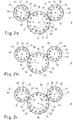
- the trough carrier bodies 35, 36, 37 are designed to be radially displaceable with respect to the respective drum body of the conveyor drums 31, 32, 33, whereby the trough carrier bodies are displaced at the same time 35, 36, 37 the pitch between the receiving troughs and the trough center axes of the receiving troughs of the trough carrier bodies 35, 36, 37 in the respective conveyor drum 31, 32, 33 can be changed.
- the spacing between two receiving troughs of a conveyor drum can be varied, the shape of the receiving troughs formed on the trough carrier bodies 35, 36, 37 being unchangeable and thus having a predetermined, fixed trough contour.
- the conveyor drums 31, 32, 33 are driven by drives (not shown here) or a drive (not shown here), so that the conveyor drums 31, 32, 33 are driven about their respective axes of rotation 41, 42, 43.
- Fig. 2a it is shown schematically that the conveyor drums 31, 32, 33 convey rod-shaped articles 21 (as rod-shaped articles of a first type), the rod-shaped articles 21 being transferred from the conveyor drum 31 to the following conveyor drum 32 in a transfer area 38.
- the rod-shaped articles 21 are then conveyed on the conveyor drum 32 to a second transfer area 39 between the conveyor drum 32 and the following conveyor drum 33, so that the rod-shaped articles 21 are transferred to the conveyor drum 33 in the transfer area 39.
- Filter cigarettes are produced on the filter attachment machine F, with tobacco sticks and / or filter stoppers being conveyed individually or in groups as rod-shaped articles 21.
- filter cigarettes with a predetermined diameter are produced on the filter attachment machine F.
- the conveyor drums 31, 32, 33 are stopped (cf. Fig.2b ).
- the conveyor drums 31, 32, 33 are retained in their relative arrangement, the trough support bodies 35, 36, 37 being moved outward in their radial position in order to maintain the same conveyor drums 31 , 32, 33 with their stationary axes of rotation 41, 42, 43 to reduce the distance between the conveyor drums 31, 32, 33 in the transfer areas 38, 39, so that when conveying rod-shaped articles 22 (as rod-shaped articles of a second type), the a smaller diameter than the rod-shaped article 21 according to the in Fig.
- the trough support bodies 35, 36, 37 are moved radially outward, the movement being carried out using an adjusting device (not shown here). As a result, the trough carrier bodies 35, 36, 37 in the transfer areas 38, 39 between the adjacent conveyor drums 31, 32, 33 are brought closer to one another.
- the trough carrier bodies 35, 36, 37 are in a changed position or working position (cf. Figure 2c ) shifted so that the pitch of the receiving troughs is changed on the respective conveyor drums 31, 32, 33, whereby the radial distance between the trough centers or trough bottoms of the receiving troughs for rod-shaped articles with a small diameter differs from the arc of the trough center axes of the receiving troughs for articles with a larger diameter.
- the radial distance to the axis of rotation of the conveyor drum when conveying rod-shaped articles with a small diameter is greater than the radial distance when conveying rod-shaped articles with a larger diameter. It is provided according to the invention that when rod-shaped articles 21 (as articles of a first type) (cf. Fig. 2a ) in the receiving troughs of the respective conveyor drums 31, 32, 33 the circular arc of the central longitudinal axes of the rod-shaped articles 21 the circular arc of the central longitudinal axes of the rod-shaped articles 22 (as an article of the second type) (cf. Figure 2c ) corresponds approximately.
- FIG. 3a is a schematic detailed view of the conveyor drum 31 (see. Figures 2a to 2c ) shown in cross section.
- Figure 3b a section through the conveyor drum 31 is shown schematically in detail.
- the conveyor drum 31 has a drum body 34 which has recesses in which the radially movable trough carrier bodies 35 are arranged to be displaceable and complementary in shape.
- the trough carrier bodies 35 each have a receiving trough 45 on their outside, which has a constant, i.e. constant, shape in cross section.
- the trough support bodies 35 have radially running suction bores 46 so that when the rod-shaped articles 21 are conveyed in the receiving troughs 45, the bar-shaped articles 21 are or will be subjected to negative pressure during the conveyance.
- the radial displacement of the trough carrier bodies 35 means that the pitch of the receiving troughs 45 can be changed, so that the pitch, i. E. the transverse axial distance between the receiving troughs 45 of the conveyor drum 31 is adjusted.
- Figure 3b shows a cross-section through the conveyor drum 31 or through a trough carrier body 35.
- horizontally displaceable or adjustable adjustment bodies 61, 62 are arranged, each of which has a guide surface inclined to the horizontal, on which a sliding surface of the trough carrier body is also inclined to the horizontal 35 rests on its underside.
- the adjusting body 61 is spaced apart from the adjusting body 62 in the longitudinal axial direction, the two adjusting bodies 61, 62 being connected to one another by means of an adjusting screw 63.
- the adjusting screw 63 has a left-right thread, so that by turning the adjusting screw 63 the distance between the adjusting bodies 61, 62 is changed, whereby due to the inclined contact surfaces of the adjusting bodies 61, 62 the simultaneous horizontal movement of the adjusting bodies 61, 62 becomes a radial Movement of the trough support body 35 leads.
- springs 64 are designed as counter bearings for the recess support body in order to press the recess support body 35 against the adjustment bodies 61, 62.
- the trough support body 35 formed as segments, for example, as adjusting bodies 61, 62 for the trough support body 35, cone expansion rings are arranged in the drum body of the conveyor drum 31, which are pulled apart or together by means of the adjusting screw 63 provided as a central screw. Due to the axial movement of the expansion rings as adjusting bodies 61, 62, the trough support bodies 35 are pushed apart or pressed radially inward, whereby the pitch circle of the central longitudinal axes of the rod-shaped articles 21, 22 to be conveyed can be kept constant when the diameter of the rod-shaped articles changes. The setting of the trough support body 35 can be carried out or take place continuously.
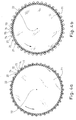
- FIGs 4a, 4b each shows a schematic view of a conveyor drum 71 of the tobacco processing industry, rod-shaped articles 21, 22 of different diameter being conveyed on the conveyor drum 71.
- the Figures 5a and 5b schematically show sections of the conveyor drum 71.
- the conveyor drum 71 has in the circumferential direction as a support body for the rod-shaped articles 21, 22 support rods or support pins 73, 74, with a pair of support pins 73, 74 forming a receiving trough for the rod-shaped articles 21, 22 to be conveyed between the support pins.
- the support pins 73, 74 are aligned parallel to the axis of rotation 72 of the conveyor drum 71, the support pins 73, 74 being mounted in the circumferential direction about a pivot axis 75, 76 eccentrically to the central longitudinal axis.
- FIG. 6 is a schematic view of the support pins 73, 74 of the conveyor drum 71 (cf. Figures 4a, 4b ) shown.
- the support pins 73, 74 are mounted eccentrically about a pivot axis 75, 76, the pivot axis 75, 76 being formed outside of the central longitudinal axis of the support pins 73, 74.
- a receiving trough for the rod-shaped articles 21 and 22 to be conveyed is formed in the space, the rod-shaped articles 21, 22 to be conveyed having an approximately linear contact with the outer surface of the circular support pins 73, 74.
- the support pins 73, 74 are pivoted about their pivot axes 75, 76 when the adjustment mechanism is actuated. Due to the pivotability of the support pins 73, 74, when rod-shaped articles 21, 22 of different thicknesses are conveyed, it is possible that the central longitudinal axes 23, 24 of the rod-shaped articles 21 and 22 are conveyed on approximately the same circular arc KB.
- the rod-shaped articles 21 or 22 to be conveyed being conveyed on the same pitch circle diameter for the rod-shaped articles.
- the spacing between the trough center axes of two adjacent receiving troughs is changed.
- corresponding drives or drive devices are provided. The rotation of the support pins 73, 74 can be achieved, for example, by a drive by means of a gear or spur gear or a belt drive.
- Oval support pins 73, 74 can also be used as support pins for the rod-shaped articles.
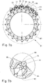
- FIG. 14 is an enlarged partial view of the receiving well marked with a circle in FIG Figure 7a shown schematically.
- the trough shaped bodies 84, 85 are designed to be displaceable with respect to the ramp-shaped elevation of the drum body 83, so that the distance between the trough shaped bodies 84, 85 can be varied, whereby the distance and also the size of the receiving trough 86 can be changed.
- the trough shaped bodies 84, 85 are spaced further apart than when receiving rod-shaped articles 22 with a smaller diameter.
- the trough center point or the trough center axis of the receiving trough 86 is changed, while the pitch between two trough center axes of two adjacent receiving troughs can be changed at the same time.
- the size of the receiving troughs 86 is adapted accordingly to the size or diameter of the rod-shaped articles 21, 22 to be conveyed for production on a filter attachment machine.
- the size or the shape of the receiving trough 86 is set or adapted as a function of the diameter of the rod-shaped articles 21, 22 to be conveyed. This ensures that when there is a change in production and when rod-shaped articles with a changed diameter are conveyed, the radial spacing of the trough centers or trough bottoms of the receiving troughs 86 is different for different diameters, with the circular arc of the central longitudinal axes of the bar-shaped articles 21, 22 to be conveyed corresponding to one another . This ensures that the central longitudinal axes 23, 24 are rod-shaped for different diameters Articles 21, 22 correspond to each other.
- FIGs 8a, 8b schematic views of an arrangement of conveyor drums 91, 92, 93 on a filter attachment machine F are shown in each case.
- the conveyor drums 91, 92, 93 are arranged transversely axially one behind the other in the conveying direction of the rod-shaped articles 21, 22 to be conveyed.
- the conveyor drum 91 conveys rod-shaped articles 22 (as a rod-shaped article of a second type) transversely axially to a transfer area between the conveyor drum 91 and the conveyor drum 92 formed with arms and transfers them to the pivotable arms 94 of the conveyor drum 92, which are provided with a trough .
- the rod-shaped articles are then conveyed on the conveyor drum 92 to a transfer area between the conveyor drum 92 and the following conveyor drum 93, so that the rod-shaped articles 22 are transferred to the conveyor drum 93 in the transfer area.
- the conveyor drums 91, 93 are each formed with drum bodies which have unchangeable receiving troughs for the rod-shaped articles 21, 22, regardless of the size of the rod-shaped articles 21, 22 to be conveyed.
- the conveyor drums 91, 93 have a constant pitch between the trough center axes of the receiving troughs.
- the pivotable arms 94 of the conveyor drum 92 are pivoted using a pivoting link, not shown here, the central axis of the troughs of the receiving troughs of the arms 94 during an elliptical movement path one complete revolution of the conveyor drum 92.
- the pivoting link which cannot be changed in shape, for the pivoting movement of the arms 94 is set as a function of the diameter of the rod-shaped articles 21, 22 to be conveyed.
- the pivoting link is formed by a cam, the position of the receiving troughs of the arms 94 being set as a function of the diameter of the rod-shaped articles 21, 22 to be conveyed by rotating the pivoting link or the cam.
- the cam disk or the swivel link can be adjusted manually or by a drive device.
- Rod-shaped articles 22 with a smaller diameter conveyed on the conveyor drum 92 are conveyed with their central longitudinal axes along an elliptical path, the receiving troughs of the pivotable arms 94 being moved during a complete revolution with their trough central axes along an elliptical path due to the pivoting link cooperating with the arms 94.
- the swivel link or the cam on the conveyor drum is conveyed 92 changed in their relative position in relation to the arms 94 to be pivoted, so that the elliptical path for the trough center axes of the arms 94 is rotated by a predetermined angle in relation to the elliptical path when conveying rod-shaped articles 21 with a smaller diameter, so that the The center longitudinal axes of the rod-shaped articles 22 with a larger diameter are also moved along an elliptical path, the elliptical curved path differing from the curved path when conveying rod-shaped articles with a smaller diameter in terms of their position.
Landscapes
- Engineering & Computer Science (AREA)
- Mechanical Engineering (AREA)
- Manufacturing Of Cigar And Cigarette Tobacco (AREA)
- Cigarettes, Filters, And Manufacturing Of Filters (AREA)
- Specific Conveyance Elements (AREA)
Claims (11)
- Procédé pour transporter des articles (21, 22) en forme de bâtonnet de l'industrie de transformation du tabac, en particulier des cigarettes à filtres ou des composants en forme de bâtonnet de celles-ci, les articles (21, 22) en forme de bâtonnet étant transportés transversalement à leurs axes dans des gouttières de réception de tambours de transport (31, 32, 33) sous l'effet de la rotation des tambours de transport (31, 32, 33), les tambours de transport (31, 32, 33), tournant ou étant aptes à tourner autour de leur propre axe de rotation, étant disposés les uns derrière les autres dans le sens de transport transversale à l'axe des articles (21, 22) en forme de bâtonnet, les articles (21, 22) en forme de bâtonnet, disposés les uns derrière les autres de façon transversale à l'axe en au moins une rangée étant transférés d'un tambour de transport (31, 32, 33) sur un tambour de transport (31, 32, 33) subséquent, les articles en forme de bâtonnet qui doivent être transportés passant d'articles en forme de bâtonnet (21) d'un premier type ayant un diamètre prédéterminé à des articles en forme de bâtonnet (22) d'un deuxième type ayant un diamètre prédéterminé, le diamètre des articles (21) du premier type et le diamètre des articles (22) du deuxième type étant différent l'un de l'autre, le pas des gouttières de réception d'au moins un tambour de transport (31, 32, 33) étant modifié en fonction des articles en forme de bâtonnet à transporter de telle sorte que la distance entre au moins une surface de contact des gouttières de réception du tambour de transport (31, 32, 33) et l'axe de rotation des tambours de transport (31, 32, 33) pour les articles (21, 22) en forme de bâtonnet du premier type et la distance entre la même surface de contact des mêmes gouttières de réception des tambours de transport (31, 32, 33) et l'axe de rotation des tambours de transport (31, 32, 33) pour les articles (22) du deuxième type sont différentes, caractérisé en ce que la position des gouttières de réception des tambours de transport (31, 32, 33) est modifiée en déplaçant les gouttières de réception dans une direction radiale par rapport à l'axe de rotation des tambours de transport (31, 32, 33).
- Procédé selon la revendication 1, caractérisé en ce que le pas des gouttières de réception d'au moins un tambour de transport (31, 32, 33) est modifié en faisant varier la position des gouttières de réception vers le côté extérieur du tambour de transport (31, 32, 33, 71, 81).
- Procédé selon la revendication 1 ou la revendication 2, caractérisé en ce que dans le cas de deux tambours de transport (31, 32, 33) adjacents dans le sens de transport des articles en forme de bâtonnet, pour le transport des articles (21, 22) en forme de bâtonnet dans la zone de transfert des articles (21, 22) en forme de bâtonnet d'un tambour de transport (31, 32, 33) au tambour de transport (31, 32, 33) suivant, l'arc de cercle des axes longitudinaux centraux des articles (21, 22) en forme de bâtonnet, qui sont transportés sur le tambour de transport de distribution des articles (31, 32, 33), et l'arc de cercle des axes longitudinaux centraux des articles (21, 22) en forme de bâtonnet qui sont transportés sur le tambour de transport de réception d'articles (31, 32, 33) se rejoignent.
- Procédé selon l'une quelconque des revendications 1 à 3, caractérisé en ce que dans le cas de deux tambours de transport (31, 32, 33) adjacents dans le sens de transport des articles en forme de bâtonnet, pour le transport d'articles en forme de bâtonnet (21) du premier type, la position des gouttières de réception des deux tambours de transport (31, 32, 33) est réglée de telle sorte que, dans la zone de transfert des articles (21, 22) en forme de bâtonnet d'un tambour de transport (31, 32, 33) au tambour de transport suivant (31, 32, 33), l'arc de cercle des axes longitudinaux centraux des articles en forme de bâtonnet (21) du premier type, qui sont transportés sur le tambour de transport (31, 32, 33) qui délivre les articles (21, 22), et l'arc de cercle des axes longitudinaux centraux des articles en forme de bâtonnet (21) du premier type, qui sont transportés sur le tambour de transport recevant les articles se rejoignent et, après un changement des articles en forme de bâtonnet à transporter avec un diamètre différent pour le transport des articles en forme de bâtonnet (22) du deuxième type, la position des gouttières de réception des deux tambours de transport (31, 32, 33) est réglée de telle sorte que, dans la zone de transfert des articles (21, 22) en forme de bâtonnet d'un tambour de transport (31, 32, 33) au tambour de transport (31, 32, 33) suivant, l'arc de cercle des axes longitudinaux centraux des articles en forme de bâtonnet (22) du deuxième type, qui sont transportés sur le tambour de transport (31, 32, 33) de déchargement des articles, et l'arc de cercle des axes longitudinaux centraux des articles en forme de bâtonnet (22) du deuxième type qui sont transportés sur le tambour de transport (31, 32, 33) de réception des articles se rejoignent.
- Procédé selon l'une quelconque des revendications 1 à 4, caractérisé en ce que lors de la réception d'articles en forme de bâtonnet (21) du premier type dans les gouttières de réception dudit au moins un tambour de transport (31, 32, 33), l'arc de cercle des axes longitudinaux centraux des articles en forme de bâtonnet (21) du premier type correspond à l'arc de cercle des axes longitudinaux centraux des articles en forme de bâtonnet (22) du deuxième type lorsque des articles en forme de bâtonnet (22) du deuxième type sont reçus dans les gouttières de réception dudit au moins un tambour de transport (31, 32, 33).
- Procédé selon l'une quelconque des revendications 1 à 5, caractérisé en ce que les positions des axes de rotation des tambours de transport (31, 32, 33) restent inchangées lors du transport des articles en forme de bâtonnet (21) du premier type et lors du transport des articles en forme de bâtonnet (22) du deuxième type.
- Procédé selon l'une quelconque des revendications 1 à 6, caractérisé en ce que les tambours de transport (31, 32, 33) prévus pour le transport des articles (21, 22) en forme de bâtonnet sont conservés.
- Agencement pour transporter des articles (21, 22) en forme de bâtonnet de l'industrie de transformation du tabac, en particulier des cigarettes à filtres ou leurs composants en forme de bâtonnet, avec une pluralité de tambours de transport (31, 32, 33) tournant ou aptes à tourner autour de leur propre axe de rotation pour le transport, transversalement à leur axes, d'articles en forme de bâtonnets (21, 22) de l'industrie de transformation du tabac, les tambours de transport (31, 32, 33) étant disposés les uns après les autres dans le sens de transport transversalement à l'axe des articles en forme de bâtonnet, les tambours de transport (31, 32, 33) pour recevoir des articles (21, 22) en forme de bâtonnet sont formés chacun avec des gouttières de réception ayant un contour de gouttière ; pour un changement des articles (21, 22) en forme de bâtonnet à transporter depuis des articles en forme de bâtonnet (21) d'un premier type ayant un diamètre prédéterminé, en des articles en forme de bâtonnet (22) d'un deuxième type ayant un diamètre prédéterminé, le diamètre des articles (21) du premier type et le diamètre des articles (22) du deuxième type étant différents diffèrent les uns des autres, le pas des gouttières de réception d'au moins un tambour de transport (31, 32, 33) peut être modifié en fonction des articles (21, 22) en forme de bâtonnet à transporter, de sorte que la distance entre au moins une surface de contact des gouttières de réception du tambour de transport (31, 32, 33) et l'axe de rotation des tambours de transport (31, 32, 33) pour les articles en forme de bâtonnet (21) du premier type et à la distance entre la même surface de contact des mêmes gouttières de réception du tambour de transport (31, 32, 33) et l'axe de rotation des tambours de transport (31, 32, 33) pour les articles (22) du deuxième type sont différents, caractérisé en ce que les gouttières de réception dudit au moins un tambour de transport (31, 32, 33) sont conçues de façon à être mobiles dans la direction radiale.
- Agencement selon la revendication 8, caractérisé en ce que les gouttières de réception dudit au moins un tambour convoyeur (31, 32, 33) présentent chacune au moins une surface de contact de gouttière qui est mobile pour la réception des articles (21, 22) en forme de bâtonnet, de sorte que, par le mouvement de ladite au moins une surface de contact des gouttières, le pas des gouttières de réception du tambour de transport (31, 32, 33) est modifié en faisant varier la position des gouttières de réception vers le côté extérieur du tambour de transport (31, 32, 33).
- Agencement selon l'une des revendications 8 ou 9, caractérisé en ce que dans le cas de deux tambours de transport (31, 32, 33) adjacents dans le sens de transport des articles en forme de bâtonnet, pour le transport d'articles en forme de bâtonnet (21) du premier type dans la zone de transfert des articles (21, 22) en forme de bâtonnet d'un tambour de transport (31, 32, 33) sur le tambour de transport (31, 32, 33) suivant, l'arc de cercle des axes longitudinaux centraux des articles (21, 22) en forme de bâtonnet, qui sont transportés sur le tambour (31, 32, 33) de distribution d'articles, et l'arc de cercle des axes longitudinaux centraux des articles (21, 22) en forme de bâtonnet, qui sont transportés sur le tambour de transport (31, 32, 33) de réception d'articles, se rejoignent et / ou lorsque des articles en forme de bâtonnet (21) du premier type sont reçus dans les gouttières de réception dudit au moins un tambour de transport (31, 32, 33), l'arc de cercle des axes longitudinaux centraux des articles en forme de bâtonnet (21) du premier type correspondent à l'arc de cercle des axes longitudinaux centraux des articles en forme de bâtonnet (22) du deuxième type lorsque des articles en forme de bâtonnet (22) du deuxième type sont reçus dans les gouttières de réception dudit au moins un tambour de transport (31, 32, 33).
- Machine de l'industrie du tabac, en particulier machine (F) à fixer les bouts-filtres, pour la fabrication d'articles en forme de bâtonnets de l'industrie de transformation du tabac, en particulier de cigarettes à filtres, comportant un agencement selon l'une des revendications 8 à 10.
Priority Applications (1)
| Application Number | Priority Date | Filing Date | Title |
|---|---|---|---|
| PL17181352T PL3259999T3 (pl) | 2011-04-14 | 2012-04-02 | Przenoszenie sztabkowych artykułów przemysłu przetwórstwa tytoniu |
Applications Claiming Priority (3)
| Application Number | Priority Date | Filing Date | Title |
|---|---|---|---|
| DE102011007428A DE102011007428A1 (de) | 2011-04-14 | 2011-04-14 | Förderung von stabförmigen Artikeln der Tabak verarbeitenden Industrie |
| PCT/EP2012/001456 WO2012139720A2 (fr) | 2011-04-14 | 2012-04-02 | Transport d'articles en forme de tige de l'industrie de travail du tabac |
| EP12715582.8A EP2696708B9 (fr) | 2011-04-14 | 2012-04-02 | Transport d'articles en forme de tige de l'industrie de travail du tabac |
Related Parent Applications (2)
| Application Number | Title | Priority Date | Filing Date |
|---|---|---|---|
| EP12715582.8A Division-Into EP2696708B9 (fr) | 2011-04-14 | 2012-04-02 | Transport d'articles en forme de tige de l'industrie de travail du tabac |
| EP12715582.8A Division EP2696708B9 (fr) | 2011-04-14 | 2012-04-02 | Transport d'articles en forme de tige de l'industrie de travail du tabac |
Publications (2)
| Publication Number | Publication Date |
|---|---|
| EP3259999A1 EP3259999A1 (fr) | 2017-12-27 |
| EP3259999B1 true EP3259999B1 (fr) | 2020-08-19 |
Family
ID=45992155
Family Applications (2)
| Application Number | Title | Priority Date | Filing Date |
|---|---|---|---|
| EP17181352.0A Active EP3259999B1 (fr) | 2011-04-14 | 2012-04-02 | Acheminement d'articles en forme de tige de l'industrie de traitement du tabac |
| EP12715582.8A Active EP2696708B9 (fr) | 2011-04-14 | 2012-04-02 | Transport d'articles en forme de tige de l'industrie de travail du tabac |
Family Applications After (1)
| Application Number | Title | Priority Date | Filing Date |
|---|---|---|---|
| EP12715582.8A Active EP2696708B9 (fr) | 2011-04-14 | 2012-04-02 | Transport d'articles en forme de tige de l'industrie de travail du tabac |
Country Status (5)
| Country | Link |
|---|---|
| EP (2) | EP3259999B1 (fr) |
| CN (2) | CN103491812B (fr) |
| DE (1) | DE102011007428A1 (fr) |
| PL (2) | PL3259999T3 (fr) |
| WO (1) | WO2012139720A2 (fr) |
Families Citing this family (17)
| Publication number | Priority date | Publication date | Assignee | Title |
|---|---|---|---|---|
| CN103692553B (zh) * | 2013-11-30 | 2016-11-23 | 南通剑桥输送设备有限公司 | 一种混合用传输带 |
| DE102014204707A1 (de) * | 2014-03-13 | 2015-09-17 | Hauni Maschinenbau Ag | Aufnahmevorrichtung zur Aufnahme von Artikeln der Tabak verarbeitenden Industrie |
| WO2015160809A1 (fr) * | 2014-04-14 | 2015-10-22 | Altria Client Services Inc. | Tambour rotatif ainsi que procédé et système l'utilisant pour la production automatisée de dispositifs de vapeur électronique |
| EA201692055A1 (ru) * | 2014-04-14 | 2017-05-31 | Олтриа Клайент Сервисиз Ллк | Способ и система для автоматизированного изготовления электронных устройств для курения |
| EP3206514A4 (fr) | 2014-10-16 | 2018-06-20 | Altria Client Services LLC | Cylindre d'assemblage et système et procédé utilisant celui-ci pour la production automatisée de dispositifs de vapotage |
| CN107108063A (zh) | 2014-12-19 | 2017-08-29 | 奥驰亚客户服务有限责任公司 | 用于电子烟装置的自动化生产的施加标签的系统和方法 |
| DE102015200803B4 (de) * | 2015-01-20 | 2016-09-01 | Hauni Maschinenbau Gmbh | Fördertrommel der Tabak verarbeitenden Industrie |
| GB201609415D0 (en) * | 2016-05-27 | 2016-07-13 | British American Tobacco Co | Drum for a tobacco industry product manufacturing apparatus |
| IT201600104272A1 (it) | 2016-10-18 | 2018-04-18 | Gd Spa | Tamburo convogliatore e metodo per il trasporto ed il trasferimento di sigarette e/o filtri, semplici o composti per una macchina confezionatrice di prodotti del tabacco |
| US10889453B2 (en) | 2017-05-16 | 2021-01-12 | Philip Morris Products S.A. | Transfer wheel and method for transferring objects |
| CN107380968B (zh) * | 2017-09-06 | 2023-05-30 | 四川三联新材料有限公司 | 爆珠有序排列设备及香烟生产线 |
| DE102017219503A1 (de) * | 2017-11-02 | 2019-05-02 | Bausch + Ströbel Maschinenfabrik Ilshofen GmbH + Co. KG | Verstellbares Vakuumrad |
| DE102018103635A1 (de) * | 2018-02-19 | 2019-08-22 | Hauni Maschinenbau Gmbh | Multisegmentproduktherstellung der Tabak verarbeitenden Industrie |
| CN109365299B (zh) * | 2018-10-17 | 2024-02-23 | 顺丰科技有限公司 | 传输装置、传输线以及分拣设备 |
| CN109650030A (zh) * | 2018-12-20 | 2019-04-19 | 浙江新发现机械制造有限公司 | 一种纸容器半成品转送装置 |
| DE102019134097A1 (de) * | 2019-12-12 | 2021-06-17 | Hauni Maschinenbau Gmbh | Fördertrommel der Tabak verarbeitenden Industrie |
| DE102021121351A1 (de) | 2021-08-17 | 2023-02-23 | Körber Technologies Gmbh | Fördertrommel der Tabak verarbeitenden Industrie |
Family Cites Families (19)
| Publication number | Priority date | Publication date | Assignee | Title |
|---|---|---|---|---|
| JPS5030265A (fr) † | 1973-05-23 | 1975-03-26 | ||
| GB1522596A (en) * | 1974-10-15 | 1978-08-23 | Hauni Werke Koerber & Co Kg | Production of filter plugs |
| US4745932A (en) * | 1985-07-10 | 1988-05-24 | G.D. Societa Per Azioni | Filter assembly machine |
| IT1222773B (it) † | 1986-10-30 | 1990-09-12 | Hauni Werke Koerber & Co Kg | Dispositivo trasportatore per trasportare articolare a bastoncino dell'industria di lavorazione del tabacco |
| IT1229428B (it) | 1988-06-11 | 1991-08-08 | Hauni Werke Koerber & Co Kg | Dispositivo di taglio. |
| DE19722799A1 (de) * | 1997-05-30 | 1998-12-03 | Hauni Maschinenbau Ag | Verfahren zum Bearbeiten eines Streifens und Anordnung in einer Filteransetzmaschine |
| CN1204483A (zh) * | 1997-05-30 | 1999-01-13 | 豪尼机械制造股份公司 | 加工条带的方法和滤嘴安置机中的装置 |
| GB9809720D0 (en) † | 1998-05-06 | 1998-07-08 | Molins Plc | Cigarette making machine |
| DE10141703A1 (de) † | 2001-08-25 | 2003-03-06 | Hauni Maschinenbau Ag | Übertragungsvorrichtung und Verfahren zum Übertragen von Artikeln der tabakverarbeitenden Industrie |
| ES2262920T3 (es) * | 2003-04-11 | 2006-12-01 | Hauni Maschinenbau Ag | Procedimiento para la union de componentes de articulos de fumador. |
| DE10344381A1 (de) * | 2003-09-23 | 2005-05-04 | Hauni Maschinenbau Ag | Fördertrommel mit Spanneinrichtung |
| US7165668B2 (en) † | 2003-10-21 | 2007-01-23 | Hauni Maschinenbau Ag | Apparatus and method for the delivery of rod-shaped articles |
| ITBO20040239A1 (it) * | 2004-04-22 | 2004-07-22 | Gd Spa | Unita' di trasferimento di articoli allungati |
| DE102005012810A1 (de) * | 2005-03-17 | 2006-10-05 | Hauni Maschinenbau Ag | Verfahren zur Herstellung von Filterzigaretten |
| ITBO20060718A1 (it) * | 2006-10-18 | 2008-04-19 | Gd Spa | Macchina per la produzione di filtri composti |
| CN201094274Y (zh) * | 2007-09-25 | 2008-08-06 | 中烟机械技术中心有限责任公司 | 用于生产卷烟的鼓轮装置 |
| IT1392375B1 (it) † | 2008-07-18 | 2012-03-02 | Gd Spa | Macchina confezionatrice per la produzione di filtri combinati per sigarette. |
| DE102008035383B4 (de) * | 2008-07-29 | 2013-02-07 | Hauni Maschinenbau Ag | Fördertrommeln der Tabak verarbeitenden Industrie |
| DE102012201915B3 (de) † | 2012-02-09 | 2013-01-31 | Hauni Maschinenbau Ag | Längsförderer für stabförmige Produkte der Tabak verarbeitenden Industrie und Fördereinrichtung mit einem Längsförderer und Verfahren zum Betreiben eines Längsförderers |
-
2011
- 2011-04-14 DE DE102011007428A patent/DE102011007428A1/de active Pending
-
2012
- 2012-04-02 CN CN201280017883.6A patent/CN103491812B/zh active Active
- 2012-04-02 WO PCT/EP2012/001456 patent/WO2012139720A2/fr active Application Filing
- 2012-04-02 CN CN201610812656.2A patent/CN106213578B/zh active Active
- 2012-04-02 EP EP17181352.0A patent/EP3259999B1/fr active Active
- 2012-04-02 EP EP12715582.8A patent/EP2696708B9/fr active Active
- 2012-04-02 PL PL17181352T patent/PL3259999T3/pl unknown
- 2012-04-02 PL PL12715582.8T patent/PL2696708T5/pl unknown
Non-Patent Citations (1)
| Title |
|---|
| None * |
Also Published As
| Publication number | Publication date |
|---|---|
| CN103491812A (zh) | 2014-01-01 |
| EP2696708B9 (fr) | 2023-03-29 |
| EP3259999A1 (fr) | 2017-12-27 |
| CN106213578B (zh) | 2018-04-03 |
| EP2696708A2 (fr) | 2014-02-19 |
| WO2012139720A3 (fr) | 2013-04-25 |
| PL3259999T3 (pl) | 2021-02-08 |
| DE102011007428A1 (de) | 2012-10-18 |
| CN103491812B (zh) | 2016-10-05 |
| EP2696708B2 (fr) | 2022-12-28 |
| PL2696708T5 (pl) | 2023-03-27 |
| CN106213578A (zh) | 2016-12-14 |
| PL2696708T3 (pl) | 2018-03-30 |
| EP2696708B1 (fr) | 2017-10-11 |
| WO2012139720A2 (fr) | 2012-10-18 |
Similar Documents
| Publication | Publication Date | Title |
|---|---|---|
| EP3259999B1 (fr) | Acheminement d'articles en forme de tige de l'industrie de traitement du tabac | |
| DE4008475C2 (de) | Verfahren und Vorrichtung zum Herstellen von Filterzigaretten | |
| EP2363029A1 (fr) | Tambour de transport de l'industrie de traitement du tabac | |
| EP2661971B1 (fr) | Fabrication de cigarettes à filtre | |
| EP1595463B1 (fr) | Tambour de transport pour des articles en forme de tige dans l'industrie du tabac | |
| EP1702523B1 (fr) | Procédé de fabrication de cigarettes à filtre | |
| EP1344464B1 (fr) | Procédé et dispositif pour assembler des articles à fumer | |
| EP1516547B1 (fr) | Dispositif et procédé pour transférer articles en forme de tige | |
| EP2696709B1 (fr) | Transport d'articles en forme de tige de l'industrie de transformation du tabac | |
| EP3536172B1 (fr) | Tambour coulissant de l'industrie de traitement du tabac | |
| EP2712509B2 (fr) | Transport d'articles en forme de tige de l'industrie de traitement du tabac | |
| EP2696707B1 (fr) | Transport d'articles en forme de tige de l'industrie de transformation du tabac | |
| EP1897454B1 (fr) | Agencement en forme de V d'ouvertures d'aspiration | |
| EP2604131A1 (fr) | Fonctionnement d'une machine de placement de filtre | |
| EP2481304B1 (fr) | Alimentation de produits en forme de tiges de l'industrie de traitement du tabac dans un récipient de stockage | |
| DE102022112419A1 (de) | Anordnung zum queraxialen Fördern von stabförmigen Artikeln der Tabak verarbeitenden Industrie | |
| DE102004062421B3 (de) | Verfahren zum Transportieren von stabförmigen Artikeln der Tabak verarbeitenden Industrie mit Rollfördereinrichtung | |
| EP3189740B1 (fr) | Procédé de production d'un filtre multi-segment et dispositif de production de filtre multi-segment de l'industrie de traitement du tabac | |
| DE3321737A1 (de) | Verfahren und vorrichtung zum herstellen von mundstuecklosen plainzigaretten | |
| EP1849371B1 (fr) | Écarteur pour un tambour de transport de l'industrie du tabac | |
| DE102005019682A1 (de) | Fördertrommel der Tabak verarbeitenden Industrie |
Legal Events
| Date | Code | Title | Description |
|---|---|---|---|
| PUAI | Public reference made under article 153(3) epc to a published international application that has entered the european phase |
Free format text: ORIGINAL CODE: 0009012 |
|
| STAA | Information on the status of an ep patent application or granted ep patent |
Free format text: STATUS: REQUEST FOR EXAMINATION WAS MADE |
|
| 17P | Request for examination filed |
Effective date: 20170714 |
|
| AC | Divisional application: reference to earlier application |
Ref document number: 2696708 Country of ref document: EP Kind code of ref document: P |
|
| AK | Designated contracting states |
Kind code of ref document: A1 Designated state(s): AL AT BE BG CH CY CZ DE DK EE ES FI FR GB GR HR HU IE IS IT LI LT LU LV MC MK MT NL NO PL PT RO RS SE SI SK SM TR |
|
| RIN1 | Information on inventor provided before grant (corrected) |
Inventor name: KALUS, PETER Inventor name: PLAEHN, DIETER Inventor name: ROTTMANN, FRANZ Inventor name: FOLGER, MANFRED Inventor name: SCHLISIO, SIEGFRIED Inventor name: STUEBER, REINHARD Inventor name: PAWELKO, KARL-HEINZ Inventor name: KLEINE WAECHTER, MICHAEL |
|
| GRAP | Despatch of communication of intention to grant a patent |
Free format text: ORIGINAL CODE: EPIDOSNIGR1 |
|
| STAA | Information on the status of an ep patent application or granted ep patent |
Free format text: STATUS: GRANT OF PATENT IS INTENDED |
|
| RIC1 | Information provided on ipc code assigned before grant |
Ipc: A24C 5/32 20060101AFI20200226BHEP Ipc: A24C 5/47 20060101ALI20200226BHEP Ipc: B65G 47/84 20060101ALI20200226BHEP |
|
| INTG | Intention to grant announced |
Effective date: 20200325 |
|
| GRAS | Grant fee paid |
Free format text: ORIGINAL CODE: EPIDOSNIGR3 |
|
| GRAA | (expected) grant |
Free format text: ORIGINAL CODE: 0009210 |
|
| STAA | Information on the status of an ep patent application or granted ep patent |
Free format text: STATUS: THE PATENT HAS BEEN GRANTED |
|
| AC | Divisional application: reference to earlier application |
Ref document number: 2696708 Country of ref document: EP Kind code of ref document: P |
|
| AK | Designated contracting states |
Kind code of ref document: B1 Designated state(s): AL AT BE BG CH CY CZ DE DK EE ES FI FR GB GR HR HU IE IS IT LI LT LU LV MC MK MT NL NO PL PT RO RS SE SI SK SM TR |
|
| REG | Reference to a national code |
Ref country code: CH Ref legal event code: EP |
|
| REG | Reference to a national code |
Ref country code: DE Ref legal event code: R096 Ref document number: 502012016311 Country of ref document: DE |
|
| REG | Reference to a national code |
Ref country code: AT Ref legal event code: REF Ref document number: 1302936 Country of ref document: AT Kind code of ref document: T Effective date: 20200915 |
|
| REG | Reference to a national code |
Ref country code: IE Ref legal event code: FG4D Free format text: LANGUAGE OF EP DOCUMENT: GERMAN |
|
| REG | Reference to a national code |
Ref country code: NL Ref legal event code: FP |
|
| REG | Reference to a national code |
Ref country code: LT Ref legal event code: MG4D |
|
| PG25 | Lapsed in a contracting state [announced via postgrant information from national office to epo] |
Ref country code: NO Free format text: LAPSE BECAUSE OF FAILURE TO SUBMIT A TRANSLATION OF THE DESCRIPTION OR TO PAY THE FEE WITHIN THE PRESCRIBED TIME-LIMIT Effective date: 20201119 Ref country code: BG Free format text: LAPSE BECAUSE OF FAILURE TO SUBMIT A TRANSLATION OF THE DESCRIPTION OR TO PAY THE FEE WITHIN THE PRESCRIBED TIME-LIMIT Effective date: 20201119 Ref country code: LT Free format text: LAPSE BECAUSE OF FAILURE TO SUBMIT A TRANSLATION OF THE DESCRIPTION OR TO PAY THE FEE WITHIN THE PRESCRIBED TIME-LIMIT Effective date: 20200819 Ref country code: GR Free format text: LAPSE BECAUSE OF FAILURE TO SUBMIT A TRANSLATION OF THE DESCRIPTION OR TO PAY THE FEE WITHIN THE PRESCRIBED TIME-LIMIT Effective date: 20201120 Ref country code: HR Free format text: LAPSE BECAUSE OF FAILURE TO SUBMIT A TRANSLATION OF THE DESCRIPTION OR TO PAY THE FEE WITHIN THE PRESCRIBED TIME-LIMIT Effective date: 20200819 Ref country code: SE Free format text: LAPSE BECAUSE OF FAILURE TO SUBMIT A TRANSLATION OF THE DESCRIPTION OR TO PAY THE FEE WITHIN THE PRESCRIBED TIME-LIMIT Effective date: 20200819 Ref country code: PT Free format text: LAPSE BECAUSE OF FAILURE TO SUBMIT A TRANSLATION OF THE DESCRIPTION OR TO PAY THE FEE WITHIN THE PRESCRIBED TIME-LIMIT Effective date: 20201221 Ref country code: FI Free format text: LAPSE BECAUSE OF FAILURE TO SUBMIT A TRANSLATION OF THE DESCRIPTION OR TO PAY THE FEE WITHIN THE PRESCRIBED TIME-LIMIT Effective date: 20200819 |
|
| PG25 | Lapsed in a contracting state [announced via postgrant information from national office to epo] |
Ref country code: LV Free format text: LAPSE BECAUSE OF FAILURE TO SUBMIT A TRANSLATION OF THE DESCRIPTION OR TO PAY THE FEE WITHIN THE PRESCRIBED TIME-LIMIT Effective date: 20200819 Ref country code: RS Free format text: LAPSE BECAUSE OF FAILURE TO SUBMIT A TRANSLATION OF THE DESCRIPTION OR TO PAY THE FEE WITHIN THE PRESCRIBED TIME-LIMIT Effective date: 20200819 Ref country code: IS Free format text: LAPSE BECAUSE OF FAILURE TO SUBMIT A TRANSLATION OF THE DESCRIPTION OR TO PAY THE FEE WITHIN THE PRESCRIBED TIME-LIMIT Effective date: 20201219 |
|
| PG25 | Lapsed in a contracting state [announced via postgrant information from national office to epo] |
Ref country code: RO Free format text: LAPSE BECAUSE OF FAILURE TO SUBMIT A TRANSLATION OF THE DESCRIPTION OR TO PAY THE FEE WITHIN THE PRESCRIBED TIME-LIMIT Effective date: 20200819 Ref country code: DK Free format text: LAPSE BECAUSE OF FAILURE TO SUBMIT A TRANSLATION OF THE DESCRIPTION OR TO PAY THE FEE WITHIN THE PRESCRIBED TIME-LIMIT Effective date: 20200819 Ref country code: CZ Free format text: LAPSE BECAUSE OF FAILURE TO SUBMIT A TRANSLATION OF THE DESCRIPTION OR TO PAY THE FEE WITHIN THE PRESCRIBED TIME-LIMIT Effective date: 20200819 Ref country code: EE Free format text: LAPSE BECAUSE OF FAILURE TO SUBMIT A TRANSLATION OF THE DESCRIPTION OR TO PAY THE FEE WITHIN THE PRESCRIBED TIME-LIMIT Effective date: 20200819 Ref country code: SM Free format text: LAPSE BECAUSE OF FAILURE TO SUBMIT A TRANSLATION OF THE DESCRIPTION OR TO PAY THE FEE WITHIN THE PRESCRIBED TIME-LIMIT Effective date: 20200819 |
|
| REG | Reference to a national code |
Ref country code: DE Ref legal event code: R097 Ref document number: 502012016311 Country of ref document: DE |
|
| PG25 | Lapsed in a contracting state [announced via postgrant information from national office to epo] |
Ref country code: ES Free format text: LAPSE BECAUSE OF FAILURE TO SUBMIT A TRANSLATION OF THE DESCRIPTION OR TO PAY THE FEE WITHIN THE PRESCRIBED TIME-LIMIT Effective date: 20200819 Ref country code: AL Free format text: LAPSE BECAUSE OF FAILURE TO SUBMIT A TRANSLATION OF THE DESCRIPTION OR TO PAY THE FEE WITHIN THE PRESCRIBED TIME-LIMIT Effective date: 20200819 |
|
| PLBE | No opposition filed within time limit |
Free format text: ORIGINAL CODE: 0009261 |
|
| STAA | Information on the status of an ep patent application or granted ep patent |
Free format text: STATUS: NO OPPOSITION FILED WITHIN TIME LIMIT |
|
| PG25 | Lapsed in a contracting state [announced via postgrant information from national office to epo] |
Ref country code: SK Free format text: LAPSE BECAUSE OF FAILURE TO SUBMIT A TRANSLATION OF THE DESCRIPTION OR TO PAY THE FEE WITHIN THE PRESCRIBED TIME-LIMIT Effective date: 20200819 |
|
| 26N | No opposition filed |
Effective date: 20210520 |
|
| PG25 | Lapsed in a contracting state [announced via postgrant information from national office to epo] |
Ref country code: SI Free format text: LAPSE BECAUSE OF FAILURE TO SUBMIT A TRANSLATION OF THE DESCRIPTION OR TO PAY THE FEE WITHIN THE PRESCRIBED TIME-LIMIT Effective date: 20200819 |
|
| PG25 | Lapsed in a contracting state [announced via postgrant information from national office to epo] |
Ref country code: MC Free format text: LAPSE BECAUSE OF FAILURE TO SUBMIT A TRANSLATION OF THE DESCRIPTION OR TO PAY THE FEE WITHIN THE PRESCRIBED TIME-LIMIT Effective date: 20200819 |
|
| GBPC | Gb: european patent ceased through non-payment of renewal fee |
Effective date: 20210402 |
|
| PG25 | Lapsed in a contracting state [announced via postgrant information from national office to epo] |
Ref country code: LU Free format text: LAPSE BECAUSE OF NON-PAYMENT OF DUE FEES Effective date: 20210402 |
|
| REG | Reference to a national code |
Ref country code: BE Ref legal event code: MM Effective date: 20210430 |
|
| PG25 | Lapsed in a contracting state [announced via postgrant information from national office to epo] |
Ref country code: CH Free format text: LAPSE BECAUSE OF NON-PAYMENT OF DUE FEES Effective date: 20210430 Ref country code: LI Free format text: LAPSE BECAUSE OF NON-PAYMENT OF DUE FEES Effective date: 20210430 Ref country code: GB Free format text: LAPSE BECAUSE OF NON-PAYMENT OF DUE FEES Effective date: 20210402 Ref country code: FR Free format text: LAPSE BECAUSE OF NON-PAYMENT OF DUE FEES Effective date: 20210430 |
|
| PG25 | Lapsed in a contracting state [announced via postgrant information from national office to epo] |
Ref country code: IE Free format text: LAPSE BECAUSE OF NON-PAYMENT OF DUE FEES Effective date: 20210402 |
|
| PG25 | Lapsed in a contracting state [announced via postgrant information from national office to epo] |
Ref country code: IS Free format text: LAPSE BECAUSE OF FAILURE TO SUBMIT A TRANSLATION OF THE DESCRIPTION OR TO PAY THE FEE WITHIN THE PRESCRIBED TIME-LIMIT Effective date: 20201219 |
|
| REG | Reference to a national code |
Ref country code: AT Ref legal event code: MM01 Ref document number: 1302936 Country of ref document: AT Kind code of ref document: T Effective date: 20210402 |
|
| PG25 | Lapsed in a contracting state [announced via postgrant information from national office to epo] |
Ref country code: BE Free format text: LAPSE BECAUSE OF NON-PAYMENT OF DUE FEES Effective date: 20210430 |
|
| PG25 | Lapsed in a contracting state [announced via postgrant information from national office to epo] |
Ref country code: AT Free format text: LAPSE BECAUSE OF NON-PAYMENT OF DUE FEES Effective date: 20210402 |
|
| REG | Reference to a national code |
Ref country code: DE Ref legal event code: R081 Ref document number: 502012016311 Country of ref document: DE Owner name: KOERBER TECHNOLOGIES GMBH, DE Free format text: FORMER OWNER: HAUNI MASCHINENBAU GMBH, 21033 HAMBURG, DE |
|
| REG | Reference to a national code |
Ref country code: NL Ref legal event code: HC Owner name: KOERBER TECHNOLOGIES GMBH; DE Free format text: DETAILS ASSIGNMENT: CHANGE OF OWNER(S), CHANGE OF OWNER(S) NAME; FORMER OWNER NAME: HAUNI MASCHINENBAU GMBH Effective date: 20221028 |
|
| PG25 | Lapsed in a contracting state [announced via postgrant information from national office to epo] |
Ref country code: HU Free format text: LAPSE BECAUSE OF FAILURE TO SUBMIT A TRANSLATION OF THE DESCRIPTION OR TO PAY THE FEE WITHIN THE PRESCRIBED TIME-LIMIT; INVALID AB INITIO Effective date: 20120402 Ref country code: CY Free format text: LAPSE BECAUSE OF FAILURE TO SUBMIT A TRANSLATION OF THE DESCRIPTION OR TO PAY THE FEE WITHIN THE PRESCRIBED TIME-LIMIT Effective date: 20200819 |
|
| PGFP | Annual fee paid to national office [announced via postgrant information from national office to epo] |
Ref country code: PL Payment date: 20230324 Year of fee payment: 12 |
|
| P01 | Opt-out of the competence of the unified patent court (upc) registered |
Effective date: 20230621 |
|
| PGFP | Annual fee paid to national office [announced via postgrant information from national office to epo] |
Ref country code: IT Payment date: 20230428 Year of fee payment: 12 Ref country code: DE Payment date: 20230426 Year of fee payment: 12 |
|
| PG25 | Lapsed in a contracting state [announced via postgrant information from national office to epo] |
Ref country code: MK Free format text: LAPSE BECAUSE OF FAILURE TO SUBMIT A TRANSLATION OF THE DESCRIPTION OR TO PAY THE FEE WITHIN THE PRESCRIBED TIME-LIMIT Effective date: 20200819 |
|
| PGFP | Annual fee paid to national office [announced via postgrant information from national office to epo] |
Ref country code: NL Payment date: 20240425 Year of fee payment: 13 |