EP3258980B1 - Halter für verbundflüssigkeitsbeutelsystem - Google Patents
Halter für verbundflüssigkeitsbeutelsystem Download PDFInfo
- Publication number
- EP3258980B1 EP3258980B1 EP16706765.1A EP16706765A EP3258980B1 EP 3258980 B1 EP3258980 B1 EP 3258980B1 EP 16706765 A EP16706765 A EP 16706765A EP 3258980 B1 EP3258980 B1 EP 3258980B1
- Authority
- EP
- European Patent Office
- Prior art keywords
- bag
- tubing
- system box
- lid
- chamber
- Prior art date
- Legal status (The legal status is an assumption and is not a legal conclusion. Google has not performed a legal analysis and makes no representation as to the accuracy of the status listed.)
- Active
Links
Images


Classifications
-
- A—HUMAN NECESSITIES
- A61—MEDICAL OR VETERINARY SCIENCE; HYGIENE
- A61M—DEVICES FOR INTRODUCING MEDIA INTO, OR ONTO, THE BODY; DEVICES FOR TRANSDUCING BODY MEDIA OR FOR TAKING MEDIA FROM THE BODY; DEVICES FOR PRODUCING OR ENDING SLEEP OR STUPOR
- A61M1/00—Suction or pumping devices for medical purposes; Devices for carrying-off, for treatment of, or for carrying-over, body-liquids; Drainage systems
- A61M1/36—Other treatment of blood in a by-pass of the natural circulatory system, e.g. temperature adaptation, irradiation ; Extra-corporeal blood circuits
- A61M1/3693—Other treatment of blood in a by-pass of the natural circulatory system, e.g. temperature adaptation, irradiation ; Extra-corporeal blood circuits using separation based on different densities of components, e.g. centrifuging
-
- A—HUMAN NECESSITIES
- A61—MEDICAL OR VETERINARY SCIENCE; HYGIENE
- A61M—DEVICES FOR INTRODUCING MEDIA INTO, OR ONTO, THE BODY; DEVICES FOR TRANSDUCING BODY MEDIA OR FOR TAKING MEDIA FROM THE BODY; DEVICES FOR PRODUCING OR ENDING SLEEP OR STUPOR
- A61M1/00—Suction or pumping devices for medical purposes; Devices for carrying-off, for treatment of, or for carrying-over, body-liquids; Drainage systems
- A61M1/02—Blood transfusion apparatus
- A61M1/0209—Multiple bag systems for separating or storing blood components
-
- B—PERFORMING OPERATIONS; TRANSPORTING
- B04—CENTRIFUGAL APPARATUS OR MACHINES FOR CARRYING-OUT PHYSICAL OR CHEMICAL PROCESSES
- B04B—CENTRIFUGES
- B04B11/00—Feeding, charging, or discharging bowls
-
- B—PERFORMING OPERATIONS; TRANSPORTING
- B04—CENTRIFUGAL APPARATUS OR MACHINES FOR CARRYING-OUT PHYSICAL OR CHEMICAL PROCESSES
- B04B—CENTRIFUGES
- B04B11/00—Feeding, charging, or discharging bowls
- B04B11/04—Periodical feeding or discharging; Control arrangements therefor
-
- B—PERFORMING OPERATIONS; TRANSPORTING
- B04—CENTRIFUGAL APPARATUS OR MACHINES FOR CARRYING-OUT PHYSICAL OR CHEMICAL PROCESSES
- B04B—CENTRIFUGES
- B04B5/00—Other centrifuges
- B04B5/04—Radial chamber apparatus for separating predominantly liquid mixtures, e.g. butyrometers
- B04B5/0407—Radial chamber apparatus for separating predominantly liquid mixtures, e.g. butyrometers for liquids contained in receptacles
- B04B5/0428—Radial chamber apparatus for separating predominantly liquid mixtures, e.g. butyrometers for liquids contained in receptacles with flexible receptacles
-
- B—PERFORMING OPERATIONS; TRANSPORTING
- B04—CENTRIFUGAL APPARATUS OR MACHINES FOR CARRYING-OUT PHYSICAL OR CHEMICAL PROCESSES
- B04B—CENTRIFUGES
- B04B7/00—Elements of centrifuges
- B04B7/08—Rotary bowls
-
- B—PERFORMING OPERATIONS; TRANSPORTING
- B04—CENTRIFUGAL APPARATUS OR MACHINES FOR CARRYING-OUT PHYSICAL OR CHEMICAL PROCESSES
- B04B—CENTRIFUGES
- B04B5/00—Other centrifuges
- B04B5/04—Radial chamber apparatus for separating predominantly liquid mixtures, e.g. butyrometers
- B04B5/0407—Radial chamber apparatus for separating predominantly liquid mixtures, e.g. butyrometers for liquids contained in receptacles
- B04B2005/0435—Radial chamber apparatus for separating predominantly liquid mixtures, e.g. butyrometers for liquids contained in receptacles with adapters for centrifuge tubes or bags
Definitions
- liquids including biological liquids that are separated into components.
- the components may then be utilized after separation.
- a biological fluid that is separated into components is whole blood.
- whole blood obtained by blood donations is separated into its components such as red blood cells, platelets and plasma.
- the components may then be individually transfused to a patient. It is believed that component transfusion, instead of transfusion of whole blood, may lessen the burden on a patient's circulatory system and reduce possible side effects of transfusion.
- Whole blood obtained by blood donation may be centrifuged to separate the whole blood into its components.
- the whole blood may be separated into a PPP (platelet poor plasma) fraction, a CRC (concentrated red blood cells) fraction, and buffy coat.
- the buffy coat may contain leukocytes, platelets and red blood cells.
- the buffy coat has a large proportion of young fresh platelets.
- whole blood may be separated into blood components including platelet poor plasma, concentrated red cells and buffy coat, which may be stored and transported in separate storage bags.
- the storage bags may be connected by tubing to create a bag system.
- a bag system for storage of blood components may be mounted in a separator device, such as a centrifuge.
- a separator device such as a centrifuge.
- position of bags, and operation of the centrifuge it may be burdensome to position bags and route tubing when mounting a bag system in a centrifuge.
- there may be kinking (torsion or sharp bending) of tubing which may affect how the bag system operates during a separation process.
- Embodiments of the present invention have been made in light of these and other considerations. However, the relatively specific problems discussed above do not limit the applicability of the embodiments of the present invention.
- US 2007/179423 A1 discloses a method of collecting and separating whole blood into components.
- Embodiments of the disclosure provide for a system box that holds a bag system used with a centrifuge apparatus to separate a composite liquid into components.
- the composite liquid may be whole blood.
- the system box may include a first chamber with a first opening for inserting a first bag of the bag system, a second chamber with a second opening for inserting a second bag of the bag system, and a lid that is moveable from an open position to a closed position where it covers at least a portion of the first chamber.
- the lid may include an interior surface and an exterior surface. When the lid is closed, the inside surface may cover at least a portion of the first chamber.
- the inside surface may include a frangible breaking ridge that when the lid is closed is positioned over a recess.
- the lid may also include a tube securing ridge, which may push against tubing to ensure tubing stays positioned in a channel adjacent one or more sensor(s).
- the system box may include one or more tubing guide posts.
- the tubing guide posts allow different tubing lengths to be wrapped around the guide posts in different ways. Accordingly, bag systems with varying tubing lengths may be used in the system boxes that include the tubing guide posts.
- a system box to include a tubing holder for holding segments of tubing.
- segments of tubing containing whole blood may be placed inside the tubing holder.
- the tubing holder may be angled with respect to an axis of rotation of a centrifuge apparatus, which may result in centrifugal force maintaining the tubing segments in the tubing holder.
- a system box may include a latch system for engaging a lid.
- the latch system may be connected to valves so that when a lid is closed and engaged by the latch system, the valves may be closed. When the lid is not engaged with the latch system, the valves may be open. The valves may remain closed even after the lid is opened, such as for example after a separation process has been completed.
- the disclosure provide for a system box with a liquid guard.
- the liquid guard may include a curved wall that is designed to catch liquid that may leak from a bag system mounted on the system box.
- the curved wall may extend above most if not all of the features of the system box to catch liquid and direct it into chambers in the system box.
- Liquid guard (or other portion of an outer wall) may include some indicia indicating, e.g., such as to an operator, a particular component so that a bag of the bag system that will store the component is placed in a corresponding chamber.
- the disclosure also provides for a system for separating components from a composite liquid.
- the system may include a bag system with a first bag for storing the composite liquid (e.g., whole blood) and a second bag for storing at least one component separated from the composite liquid.
- the system may further include a system box for holding the bag system during separation.
- the system box includes a first chamber for storing the first bag and a second chamber for storing the second bag.
- the system box may further include a third chamber for toring a third bag, which may contain a preservative solution.
- the system box may also include a lid for covering at least a portion of the first chamber.
- the lid includes at least a first ridge for breaking a frangible of the bag system.
- Methods may include loading a bag system onto a system box.
- the loading may include positioning a first bag of a bag system into a first chamber of the system box.
- the first bag comprises a volume of composite liquid (e.g., whole blood).
- a portion of tubing that connects the first bag to a second bag is then routed.
- a second bag of the bag system may then be positioned into a second chamber of the system box.
- the method may then include breaking a frangible to open fluid communication between the first bag and the second bag by closing a lid that covers a portion of the first chamber.
- the composite liquid may then be separated into a plurality of components (e.g., plasma, platelets, red blood cells).
- the bag system may then be unloaded from the system box.
- One of the separated components may be stored in the second bag.
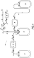
- bag system 10 illustrated in FIG. 1 may be used for separating components from composite liquids, such as by centrifuging.
- whole blood containing a plurality of components may be separated into three components, namely a low-density component (relative low-density component), a medium-density component (relative medium-density component) and a high-density component (relative high-density component)
- whole blood is centrifuged into three components including plasma, buffy coat and concentrated red cells), and containing and preserving the components separately in different bags.
- the bag system 10 may include: a first bag 12 in which, a composite liquid, e.g., blood, containing a plurality of components may be contained; a second bag 14 in which a medium-density component obtained by centrifuging the blood in the first bag 12 may be stored; a third bag 16 in which a low-density component obtained by centrifuging the blood in the first bag 12 may be contained; a first tube 18 through which an upper portion of the first bag 12 and an inlet 13 of the second bag 14 may be connected and through which the low-density component and the medium-density component may be transported from the first bag 12 to the second bag 14; and a second tube 20 by which an outlet 15 of the second bag 14 and the third bag 16 may be connected and through which the low-density component may be transported from the first bag 12 to the third bag 16 by way of the first tube 18 and the second bag 14.
- a composite liquid e.g., blood
- the bag system 10 may include: a first bag 12 in which,
- the first bag 12, the second bag 14 and the third bag 16 may each be fabricated by a method in which flexible sheet materials made of a flexible resin such as polyvinyl chloride and/or polyolefin are placed on each other and are fused (by heat fusing or high-frequency fusing) or adhered to each other at peripheral sheet portions into a bag.
- a first sample bag 32 and a red cell bag 38 may also be in the form of a bag. In other embodiments, 12, 14, 16, 32, and 38 may be in some other form of container.
- An anticoagulant may in embodiments be preliminarily contained in the first bag 12.
- the anticoagulant may be a solution, and non-limiting examples thereof include but are not limited to ACD-A solution, CPD solution, CPDA-1 solution, and heparin sodium solution.
- the proper amount of anticoagulant corresponding to the amount of blood to be collected may be included in first bag 12.
- a blood collection tube (proximal-side blood collection tube) 22 may be connected to an upper portion of the first bag 12.
- a clamp 23 by which a lumen in the blood collection tube 22 is closed and opened may be provided at an intermediate portion of the blood collection tube 22.
- One end of a sealing member (e.g., a frangible or clik-tip) 24 may be connected to the other end of the blood collection tube 22.
- the sealing member 24 may be configured so as to close the channel (which may be provided, at least in part, by a portion of sealing member 24) in an initial condition and to open the channel by a breaking operation.
- Such a sealing member 24 as this may include a tube formed, for example, from a flexible resin such as vinyl chloride, and a tubular body which may be connected to the inside of the tube in a liquid-tight manner, may be closed at one end thereof and may have a brittle part at a portion in the longitudinal direction thereof.
- the tubular body may be bent from the outside of the tube by fingers or the like to thereby break the brittle part. Consequently, a channel in the tube which has been closed by the tubular body is opened, whereby the sealing member 24 is put into an open state.
- a first port 26A of a branch connector 26 To the other end of the sealing member 24 may be connected a first port 26A of a branch connector 26.
- a blood collection tube (distal-side blood collection tube) 28 To a second port 26B of the branch connector 26, one end of a blood collection tube (distal-side blood collection tube) 28 may be connected, and to the other end of the blood collection tube 28, a blood collection needle 29 may be connected.
- a cap 27A may be used to cover the blood collection needle 29, and, after use, a needle guard 27B may be mounted to the blood collection needle 29.
- the needle guard 27B may be so disposed as to be movable along the longitudinal direction of the blood collection tube 28.
- a branch tube 30 may be connected to a third port 26C of the branch connector 26, one end of a branch tube 30 may be connected.
- a clamp 31 may be provided by which a channel in the branch tube 30 may be closed and opened.
- bag 32 may be connected to the other end of the branch tube 30.
- the sealing member 24 may be kept in a closed state (initial state)
- the clamp 31 may be in an open state, whereby the blood is inhibited from flowing to the blood collection tube 22 and to the first bag 12. The blood therefore may first flow into the sample bag 32 through the blood collection tube 28, the branch connector 26 and the branch tube 30.
- a sampling port 34 may be connected to the sample bag 32, and, by attaching a blood collection tube to the sampling port 34, the collected blood may be sampled into the blood collection tube.
- the samples of collected blood may be used for testing.
- the part(s) ranging from the branch connector 26 to the sampling port 34 may be omitted.
- the bag 14 may be used in embodiments to contain (store) buffy coat.
- Bag 14 may have a bag structure of a top-and-bottom form wherein the inlet 13 is provided at one end and the outlet 15 is provided at the other end.
- the bag 14 is so set as to have a necessary and sufficient capacity, taking into account the amount of buffy coat to be collected; though the capacity may be smaller than the capacity of the first bag 12.
- the bag 16 may contain (store) and preserve plasma.
- the first tube 18 may be connected to an upper portion of the first bag 12.
- a sealing member 17 e.g., frangible, clik-tip, etc.
- the sealing member 17 may have the same, or a similar, configuration and function as sealing member 24, described above.
- a first clamp 19 by which a channel in the first tube 18 may be closed and opened may be provided at an intermediate portion of the first tube 18.
- the second tube 20 may be connected at its one end to the outlet 15 of the bag 14, and may be connected at its other end to the bag 16.
- a second clamp 21, by which a channel in the second tube 20 may be closed and opened, may be provided at an intermediate portion of the second tube 20.
- the bag system may further include a bag 38 into which concentrated red blood cells may be stored, a filter 36 which may be disposed between the first bag 12 and the red cell bag 38 and by which predetermined cells (e.g., leukocytes) may be removed, a third tube 40 connecting an upper portion of the first bag 12 and an inlet of the filter 36, and a fourth tube 42 through which an outlet of the filter 36 and the red cell bag 38 may be connected.
- the filter 36 is configured as a leukocyte removal filter.
- bag 38 may store a preservative solution that may be added to first bag 12 after other components have been removed.
- filter 36 may not be a part of system 10.
- a clamp 43 by which a channel in the third tube 40 is closed and opened is provided at an intermediate portion of the third tube 40.
- a clamp 44 by which a channel in the fourth tube 42 is closed and opened is provided at an intermediate portion of the fourth tube 42.
- Each of the tubes (inclusive of the first tube 18 and the second tube 20) in the bag system 10 may be made of a transparent flexible resin and a lumen extending between opposite ends of the tube.
- Each of the clamps (inclusive of the first clamp 19 and the second clamp 21) may be a standard pinch clamp in some embodiments.
- the clamps may have different colors according to the locations of use and their intended use.
- each of the clamps may be in an open state and the inside of each of the bags is in communication to uniformly sterilize the system.
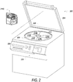
- the bag system 10 can be used, in embodiments for example, by being mounted to a centrifuge apparatus 200 as shown in FIG. 2 .
- This apparatus 200 may be used for separating whole blood contained in the first bag 12 into three layers (components) including plasma, buffy coat and concentrated red blood cells, storing the buffy coat in bag 14, while storing the plasma in bag 16, and leaving concentrated red blood cells in bag 12.
- bag 38 may include a preservative solution that can then be added to bag 12 to preserve the red blood cells.
- FIG. 1 illustrates a specific embodiment of a system with bags and tubing connected in a particular way
- tube 40 and tube 18 may be connected to a branch connector, such as branch connecter 26.
- a tube may connect the branch connector to bag 12, with tube 40 and tube 18 also being connected to the branch connector.
- bag 14 may not be in-line with bag 16 and instead may be connected to a branch connector that is also connected to tube 18.
- the centrifuge apparatus 200 may be box-shaped, and may include an openable/closable cover 204 at the top, a centrifugal drum (means for centrifuging) 208 in the inside, six unit insertion holes 212 provided at regular angular intervals inside the centrifugal drum 208, and six system boxes 216A-F inserted in respective ones of the unit insertion holes.
- the apparatus 200 may be operated based on UI controls on a console section 220 provided at the front surface, which may be controlled by a microcomputer, and may be configured to display predetermined information on a display 224.
- the bag system is loaded onto a system box such as system box 216c.
- the system box has chambers and features that allow the tubing and bags to be positioned in the system box. Examples of some features of a system box are described below.
- the system box may be already installed in apparatus 200 before the bag system is loaded onto the system box.
- the system box may be out of the apparatus and the system box may be positioned inside a separation apparatus such as centrifuge apparatus 200 after the bag system is loaded.
- system box 216c is shown with a particular shape, in other embodiments (such as the ones described below) the shape may be different and correspond to the shape of unit insertion holes in the separation apparatus.
- apparatus 200 has six slots where six system boxes may 216A-F be loaded into apparatus 200.
- system boxes 216A-F are loaded into apparatus 200.
- Six bag systems e.g., system 10 may then be loaded into apparatus 200 with one bag system being loaded into each of system boxes 216A-F.
- Each of the bag systems mounted into system boxes 216A-F may include a bag with a composite liquid, e.g., whole blood.
- Apparatus 200 creates a centrifugal field by spinning centrifugal drum 208 and system boxes 216A-F around the axis of rotation 228.
- the centrifugal field then separates the composite liquid loaded onto system boxes 216A-F into components, e.g., whole blood into, plasma, buffy coat, and red blood cells.
- components e.g., whole blood into, plasma, buffy coat, and red blood cells.
- the strength of the centrifugal field in apparatus 200 increases as you move away from the axis of rotation 228.
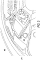
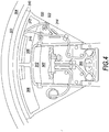
- FIGS. 3 and 4 illustrate a system box 300 installed in a centrifuge apparatus 400 according to an embodiment.
- FIGS. 5-10 illustrate system box 300 standing alone (e.g., not installed in a centrifuge apparatus) according to an embodiment.
- a bag 302 is positioned in a chamber 304 of the system box 300.
- Chamber 304 has an opening 305 for positioning bag 302 in chamber 304.
- the bag 302 may be part of a bag system such as system 10 described above with respect to FIG. 1 .
- bag 302 may be bag 12 and contain a composite liquid such as whole blood for separation into components.
- bags in chambers 306 and 308 may correspond to one or more bags 14, 16, and/or 38 shown in FIG. 1 and described above.
- tubes 310 and 312 may in embodiments correspond to tubes 18 and 40, except that they may be connected to a branch connector 314 in the embodiment shown in FIG 4 .
- system box 300 include features that allow a bag system (e.g., system 10) to be easily mounted making a process of separating a composite liquid, such as whole blood, more efficient.
- system box 300 includes a chamber 304 ( FIG. 6 ) for positioning a bag of a composite liquid (e.g., whole blood) and chambers 306 and 308 ( FIG. 7 ).
- chamber 304 includes a lid 316 that covers chamber 304.
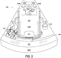
- Lid 316 includes an exterior surface 316A ( FIG. 5 ) and interior surface 316B ( FIG. 6 ).
- a handle 317 on the exterior surface 316A allows an operator to move lid 316 from an open position to a closed position.
- system box 300 includes tubing holder 318 ( FIGS. 5-9 ), valves 322 and 320 ( FIGS. 5-8 ), a number of guide posts 324A-F, a clik-tip or frangible breaking feature, e.g., ridge 326 on interior surface 316B, a liquid guard 340 on a top portion of outer wall 331, and a tube securing ridge 328 on interior surface 316B.
- lid 316 also includes a first arm 350A and a second arm 350B, which as described below may engage with hooks of a latch system when lid 316 is closed.
- FIGS. 5-10 illustrates that system box 300 generally has a wedge shape with an outer wall 331.
- the wedge shape corresponds to the shape of a space in a separation apparatus, e.g., apparatus 200 or 400 where the system box 300 is placed for separating components from a composite liquid.
- system box 300 may have other general shapes (e.g., cube, cylinder, prism, etc.) that correspond to a space in a separation apparatus.
- Outer wall 331 of system box includes a curved outer surface 331A and an inner surface 331B.
- outer wall 331 and surfaces 331A and 331B may have straight features, curved features, projections, perforations, or a combination of features.
- FIG. 5 shows system box 300 with lid 316 closed.
- lid 316 is hinged so that it may be moved from an open position ( FIG. 6 ) to a closed position.
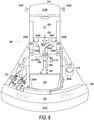
- FIG. 6 shows system box 300 with the lid 316 in the open position to show the chamber 304, where a container, e.g., bag, storing a composite liquid, e.g., whole blood, may be positioned for separation.
- a container e.g., bag
- a composite liquid e.g., whole blood
- the bag may be part of a blood bag system.
- a sensor 330 is also shown in FIG. 6 .
- At least a portion of tubing that is part of a bag system is positioned in sensor 330 to detect the presence of the various components, after separation, as they are being transferred to bags for storage.
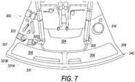
- FIG. 7 shows a close up view of system box 300.
- chambers 306 and 308 are shown.
- chambers 306 and 308 may hold bags that are used to store components of whole blood after separation, or bags with additive solution which is used for adding to separated components.
- chamber 306 includes an opening 307 through which a bag from a bag system in positioned in chamber 306.
- Chamber 308 may be adjacent to chamber 307 and includes an opening 309 through which a bag from a bag system in positioned in chamber 308.
- Chambers 306 and 308 may be located such that when system box 300 is placed in a centrifugal separation apparatus, chambers 306 and 308 may be positioned further away from a central axis of rotation, with chamber 304 being closer to the axis of rotation. System box 300, including bags loaded onto system box 300, may then be subjected to a centrifugal field which separates the composite liquid into components.
- Chamber 306 and chamber 308 may be, at least partially, between chamber 302 and outer wall 331. With this arrangement of the chambers, chambers 306 and 308 will be in a higher force region (compared to chamber
- the axis of rotation may be located on the side of system box 300 closer to guide posts 324D and 324C ( FIG. 5 ). Being in a higher force region may allow components to flow, after separation, from a bag in chamber 302 to one or more bags in chambers 306 and/or 308. As described in greater detail below, in some embodiments, there may be a tubing path located between chamber 306 (and/or 308) and outer wall 331. Having a tubing path that is in a higher force region than a bag in chamber 306 (and/or 308) may provide some advantages as described below.
- chambers 306 and 308 may be different, while in others they may be generally the same. Making chamber 306 and 308 different shapes or sizes may provide some benefits. For example, a provider may be confused as to which specific bag (e.g., an empty bag for storing a component such as plasma or a bag full of preservative) of a bag system should be placed in a chamber. The shape and/or size of a chamber may be such that only the specific bag that should be in the chamber can easily fit in the chamber. If an operator attempts to place a different bag in the chamber, it may be more difficult, which may indicate to the operator that the operator is attempting to place a bag in a chamber that is designed for a different bag.
- specific bag e.g., an empty bag for storing a component such as plasma or a bag full of preservative
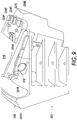
- FIGS. 8 and 9 show different sides of the system box 300 including several of the features, which are described in greater detail below.
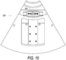
- FIG. 10 shows a bottom view of the system box 300.
- FIG. 10 shows a connector 332, which may be used to connect to electronic components (e.g., a microprocessor, user interface controls, a monitor, memory, etc.) that may be part of a centrifuge apparatus, e.g., apparatus 200 or apparatus 400.
- electronic components e.g., a microprocessor, user interface controls, a monitor, memory, etc.
- system box 300 may include a tubing holder (e.g., tubing holder 318).
- a length of tubing that holds some whole blood may be segmented into portions.
- the segmenting may be performed by an operator using a sealer that seals (e.g., by welding the tubing) whole blood in small segments along the length of tubing.
- a blood bag e.g., bag 302
- the whole blood in the individual segments is also separated.
- an operator can then look at the segments to gauge how well the separation of the whole blood has proceeded.
- the segments provide samples that can be used to determine qualities of the blood being separated, e.g., hematocrit.
- the tubing segments are stuffed in a separation chamber or in chambers with other bags of a bag system.
- the segmented portions of tubing may be stored in a tubing holder (e.g., tubing holder 318) designed specifically for holding segments of tubing with whole blood.
- FIG. 11 illustrates a holder 500 that may be included in embodiments as tubing holder 318 ( FIGS. 3-10 ).
- tubing holder 500 is angled, with respect to an axis of rotation 504 (e.g., axis 228, FIG. 2 ) such that when a centrifuge apparatus is in operation, centrifugal force will keep the tube segments in the tubing holder.
- FIG. 12 shows a close-up view of tubing holder 318 in box 300.
- tubing holder 318 is holding tubing segments.
- One feature of tube holder 318 is the ability to easily remove and replace tubing holder 318. In situations where a tubing segment bursts and whole blood leaks in tubing holder 318, the tubing holder 318 may be easily removed to be cleaned and/or replaced.
- FIG. 13 shows a tool 334 that may be used to loosen or tighten a fastener (not shown) that attaches tubing holder 318 to system box 300.
- a fastener e.g., a screw, bolt, etc.
- Tubing holder 318 may include a hole at the bottom end that allows a screw to attach holder 318 to system box 300.
- FIG. 14 illustrates tubing holder 318, which as noted above is oriented at an angle consistent with some embodiments.
- holder 318 when system box 300 is placed in a centrifuge apparatus, holder 318 will be oriented at an angle.
- the distal end 321 of holder 318 may be closer to outer wall 331 while the proximal end 319 may be further away from outer wall 331.
- this orientation will maintain the tubing segments in holder 318 using the centrifugal force generated from spinning of the centrifuge apparatus.
- embodiments may also provide for a lid that encloses the chamber where the whole blood bag is positioned.
- the lid may include additional features. Referring back to FIG. 6 , lid 316 of system box 300 is shown opened. Lid 316 includes hinges that allow it to be hinged open and closed. Lid 316 allows the whole blood bag positioned in chamber 304 respectively, to be fully contained from all sides. This may be helpful so that a bag positioned in the chamber is not extended (e.g., expands), during centrifugation, causing some other location to collapse, making removal of all of the components from the bag after separation more difficult.
- embodiments provide a mechanism for automatically opening a sealing member, e.g., a clik-tip or frangible.
- a sealing member e.g., a clik-tip or frangible.
- some bag systems may include sealing members that seal off bags until the sealing member, e.g., frangible or clik-tip, is opened.
- a frangible or clik-tip (e.g., 24 and 27 in FIG. 1 ) may be opened manually by an operator.
- An operator may bend a frangible or clik-tip to break an inside pin of the frangible or clik-tip creating fluid communication between two bags.
- An operator may utilize a relatively large number of bag systems in a day, which may result in wrist strain, hand strain, or a repetitive motion injury from having to manipulate numerous frangibles.
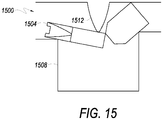
- FIG. 15 illustrates an example of a mechanism that may be used to break a frangible or clik-tip according to an embodiment.
- a frangible 1504 is positioned over a recess 1508.
- system box 300 includes a ridge 326, which may be used as a clik-tip or frangible breaker.
- ridge 326 is on the interior surface 316B of lid 316.
- tubing with a frangible may be positioned in a channel 336.
- An opening 339 of a recess 338 is in channel 336.
- a frangible may be positioned across opening 339 of recess 338 and when lid 316 is closed, ridge 326 may be pressed down on the frangible which may bend into opening 339, causing a pin in the frangible to break, allowing fluid communication from the bag positioned in chamber 304 to bags positioned in chambers 306 and/or 308.
- FIG. 6 Another feature of system box 300 is a tube securing ridge 328.
- interior surface 316B of lid 316 includes tube securing ridge 328.
- Sensor 330 in embodiments senses components as they flow through the tubing past sensor 330. For example, after separation, plasma may be transferred through the tubing.
- Sensor 330 may determine when platelets or leucocytes begin to flow in the tube, at which point, valves may be closed/opened depending on the component passing through the sensor.
- tube securing ridge 328 presses on the tube in channel 336 to ensure that a portion of the tube stays positioned in channel 336 adjacent sensor 330.
- system box 300 may include a liquid guard, such as liquid guard 340 shown in FIGS. 3-9 .
- Liquid guard 340 forms a top portion of outer wall 331.
- a bag system mounted on a system box may fail and/or leak causing liquid, e.g., blood or blood components, to leak. If the leak occurs in a centrifuge apparatus during centrifugation, liquid may be spread across the entire centrifuge apparatus requiring significant time to clean and sterilize.
- Liquid guard 340 may be designed to catch liquid and direct the liquid into one of chambers 306 and/or 308 making clean-up of leaks/spills easier and preventing liquid from spreading across the entire apparatus.
- Liquid guard 340 may in embodiments curve toward the first chamber 304, which allows it to catch liquid and direct the liquid into chambers 306 and/or 304.
- the curved portion extends at least slightly, and in some embodiments significantly, above the other features of the system box, e.g., lid 316 when lid 316 is closed.
- liquid that leaks may be directed by centrifugal force toward liquid guard 340.
- the liquid may then be caught by the curved portion of guard 340 and directed into a chamber(s), e.g., chambers 306 and 308, preventing the liquid from splattering across the entire centrifuge apparatus.
- the system box may then be removed and any liquid in the chambers cleaned.
- a liquid guard such as guard 316 may include other features.
- liquid guard 316 may include indicia indicating the type of bags that may be placed in a chamber, e.g., chambers 308 and 306.
- an outside surface of guard 340 includes the indicia "PPP" and "MAP,” indicating a particular component, such as platelet poor plasma “PPP” or a solution to be added to a component after separation, such as mannitol-adenine-phosphate "MAP.”
- PPP platelet poor plasma
- MAP a solution to be added to a component after separation
- MAP mannitol-adenine-phosphate
- a system box may be designed to ensure that most, if not all, air is pushed out of a component bag and also out of some of the length of tubing connected to the component bag.
- a component bag such as a plasma bag
- system box 300 may have a tubing path for routing tubing that connects a first bag of a bag system (e.g., bag 12) with a second bag of the bag system (e.g., bag 16).
- a tubing path 342 may be positioned between the outer wall 331 and the first chamber 304. Indeed, portion 342 is between chambers 306 and 308 and outer wall 331.
- the chambers 306 and 308 may be positioned closer to an axis of rotation of a centrifuge when the box 300 is in a centrifuge apparatus. This may ensure that an inlet of a bag in one of chambers 306 and 308 is subjected to a lower centrifugal force, than tubing in tubing path portion 342, which may push the air out of the bag and also out of a portion of tubing.
- bag inlet 346 is positioned closer to the axis of rotation than the tubing in the tubing path portion 342.
- the portion 342 of the tubing path may be provided by a number of features.
- a ledge 344 provides the tubing path portion 342.
- the tubing path portion 342 may be provided by a channel, hooks, guide posts, ridge, etc.
- guide hook 348 is part of tubing path 342 and helps maintain tubing between the outer wall 331 and chambers 306 and 308.
- Guide hook 348 and the portion of tubing path 342 may also prevent the tubing from kinking.
- the features may provide multiple functions.
- guide hook 348 may provide part of a frangible opener 349.
- a frangible may be positioned in slot 349A of opener 349 and then manipulated by an operator to break the frangible and open communication with a bag of a bag system.
- the opener 349 may be provided to open communication to a preservative solution of a bag system, such as a bag filled with MAP.
- liquid guard 340 may include indicia indicating to an operator the existence of frangible opener 349.
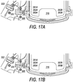
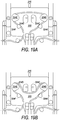
- FIG. 17A and 17B illustrate a latch system for securing a lid of a system box, according to some embodiments.
- FIG. 17A and 17B illustrate system box 300 showing lid 316 and valves 320 and 322.
- Lid 316 comprises two arms 350A and 350B that engage with two hooks 352A and 352B respectively.
- hook 352A engages arm 350A when lid 316 is closed
- hook 352B engages arm 350B when lid 316 is closed.
- the hooks 352A and 352B may be part of a latch system that secures the lid 316 during processing, and opens the lid after processing.
- the latch system may be connected to valves 320 and 322.
- the latch system may work with valves 320 and 322 to ensure that the valves are in an open position whenever lid 316 is not engaged by hooks 352A and/or 352B, as is shown in FIG. 17A .
- the latch system may close valves 320 and 322, as is shown in FIG. 17B .
- the latch system may in embodiments include a number of features.
- the latch system may include hooks, clamps, rods, arms, linkages, sensors, motors, actuators, fasteners, and the like.
- system box 300 may include pushing rods 354A and 354B that push up against lid 316 when a separation process is over. Accordingly, when a separation procedure is over, the hooks 352A and 352B may disengage the arms 350A and 350B of lid 316 and pushing rods 354A and 354B, which in embodiments may be spring loaded, may push up against lid 316 so that lid 316 is unlatched (see e.g., FIG. 13 ).
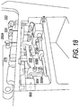
- FIG. 18 illustrates some features of an embodiment of a latch system 500.
- Latch system 500 is part of system box 300 ( FIGS. 3-10 ).
- latch system 500 includes linkage arm 502, which is attached to bracket 504 by two fasteners 506A and 506B.
- Linkage arm 502 may be attached to hooks that engage with arms of lid 316, e.g., arm 350B and arm 350A.
- the hooks may be integrally made, e.g., cast or machined as a single piece, with the linkage arm 502.
- Latch system 500 may be connected to valves 322 and 320.
- latch system 500 may include a sensor (e.g., transducer) for determining when lid 316 is in a closed position, e.g., arm 350A latched by hook 352A.
- a signal may be sent to motors 512A and 512B to close valves 322 and 320.
- a different signal may be sent, in some embodiments, to motors 512A and 512B to open valves 322 and 320.
- the latch system may have merely a mechanical connection to valves 320 and 322.
- valves 320 and 322 may be mechanically closed by portions of system 500.
- feature 351A FIGS. 17A and 17B
- a latch system may include additional features including electronic components (e.g., sensors, processors, etc.).
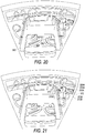
- FIG. 19A and 19B illustrate a number of guide posts 324A-F that may be used to route tubing of a bag system according to an embodiment.
- Guide posts 324A-F may be part of system box 300.
- one feature of the guide posts is that they are spaced apart in a way that allows tubing to be routed in several patterns.
- FIG. 19A illustrates one possible routing embodiment that may be used when the tubing length is relatively short.
- FIG. 19B illustrates a second possible routing embodiment that may be used when the tubing length is longer.
- Guide posts 324A-F may be used to route tubing in a variety of different patterns. This allows bag systems with different tubing lengths to be used with system box 300. As may be appreciated, without guide posts 324A-F, bag systems with longer tubing may not be able to be used with system box 300 because there may not be a way to position the extra tubing so that it does not interfere with operation of system box 300, e.g., closing of lid 316, kinking of tubing, etc.
- the guide posts have a lip (325B and 325E) that creates a channel for positioning the tubing.
- the lip may allow the tubing to fit snuggly around the guide posts to prevent the tubing from moving during separation.
- the lip may be symmetrical around the post.
- the lip e.g., 325B and 325E
- the lip may be asymmetrical and extend different lengths in different locations.
- FIG. 20 illustrates another example of some guide posts with channels that may be used in some embodiments.
- Guide posts 360, 362, and 364 are used to route tubing from a bag system. As shown in FIG. 20 , guides posts 360, 362, and 364 include channels where tubing may be positioned and held in place during separation.
- FIG. 21 some embodiments of system box 300 may include guide members that may be used to help keep tubing secured in valves 320 and 322.
- FIG. 21 shows a close-up view of guide members 370 and 372.
- Each guide member includes two prongs 370A/370B and 372A/372B.
- jaw 320A of valve 320 is positioned between prong 370A and prong 370B.
- jaw 322A of valve 322 is positioned between prong 372A and prong 372B.
- Guide members 370 and 372 help to keep tubing positioned under jaws 320A and 322A.
- the guide members may have other features such as ridges or other feature that provides some friction to maintain tubing positioned in valves 320 and 322.
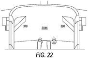
- FIG. 22 illustrates features of a chamber that may be incorporated into embodiments of a system box.
- chamber 304A includes overhang 376 and overhang 380 that are designed to be positioned above a bag, e.g., bag 302 ( FIG. 4 ) when the bag is in chamber 304A.
- a bag of composite liquid is placed inside chamber 304A and is subjected to a centrifugal field
- some portions of the bag may extend (e.g., expand), which may stretch the bag during centrifugation. This stretching may cause some other location of the bag to collapse, making removal of all of the components from the bag after separation more difficult.
- Overhang 376 and overhang 380 provide support to some of the top portions of the bag in chamber 304A to prevent expansion or stretching of the bag when it is subjected to a centrifugal field.
- overhangs 376 and 380 are provided for illustration only. Other embodiments may provide other features that function to support a bag in chamber 304A and prevent extension of a bag during centrifugation. For example, embodiments may provide for additional curved surfaces at the bottom or sides of chamber 304A. Additionally, projections from the side wall of chamber 304A may be located in particular locations, corners, edges, sides, etc. where it may be useful to support a bag in chamber 304A to avoid extension of the bag.
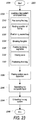
- FIG. 23 illustrates a flow chart 2300 for a process of separating components from a composite liquid.
- the composite liquid may be whole blood
- the components may be one or more of plasma, platelets, white blood cells, buffy coat, red blood cells, and combinations thereof.
- the steps in flow chart 2300 may be described below as performed by an operator, machines, or other apparatus, embodiments are not limited thereto. For example, some steps may be described as performed by an operator, while others are performed by one or more features of a system box or a separation apparatus (e.g., a centrifuge apparatus). This is done merely for illustrative purposes, and flow chart 2300 is not limited to being performed in a specific way, e.g., by any specific device, feature, or component.
- a bag system may be loaded onto a system box.
- the system box may be an embodiment of system box 300 shown and described above with respect to FIGS. 3-10 .
- the bag system may also be any suitable bag system that includes one or more bags, with one bag containing the composite liquid.
- the bag system may be a whole blood bag system that is used to collect whole blood, separate whole blood into components, store separated components, and utilize the components in patients.
- An example of a bag system is system 10 described above with respect to FIG. 1 .
- step 2308 may include a number of sub-steps. Some sub-steps are shown and described in FIG. 23 , however, other steps (not shown) may be performed in other embodiments, e.g., positioning tubing in valves for clamping. Further, the sub-steps may be performed in any order or in parallel.
- a first bag of the bag system is positioned in a first chamber of the system box.
- the first bag may comprise the composite liquid, for example whole blood.
- the first bag may be a bag in which one of the components, e.g., plasma, may be stored after separation.
- a portion of tubing that connects the first bag to a second bag of the bag system may be routed in the system box.
- Sub-step 2316 may involve routing the tubing around guide posts (e.g., 324A-F or 360, 362, and 364).
- the guide posts may be positioned to allow the tubing to be routed in different ways to accommodate different tubing lengths.
- the system box may have guide posts such as posts 324A-F shown in FIGS. 3-10 . As described above, the guide posts 324A-F allow different lengths of tubing to be accommodated in the system box.
- sub-step 2316 may involve positioning a portion of tubing in a tubing path.
- the tubing path may be located to allow one of the bags, e.g., the second bag of the bag system, to be filled with a component separated from the composite liquid while pushing air out of the bag.
- the tubing path may be located so that when the system box is subjected to a centrifugal field, a portion of tubing is positioned in a higher force region, than an inlet port of the bag being filled with the component. This may allow the bag to be filled with a component while air is pushed out of the bag.
- FIG. 16 One example of this embodiment is illustrated in FIG. 16 .
- the portion 342 of the tubing path positions tubing in a higher force region than inlet port 346, pushing air out of the bag and allowing, e.g., plasma, to fill the bag and the tubing up to valve 322.
- sub-step 2316 may also include positioning a portion of tubing adjacent a sensor to sense as components flow through the portion of tubing.
- a sensor such as sensor 330
- Sub-step 2316 may include positioning a portion of tubing in the channel adjacent sensor 330, which may sense as components such as plasma, platelets, white blood cells, and/or red blood cells flow through the tubing.
- a second bag is positioned in a second chamber of the system box.
- Flow 2300 then passes to sub-step 2324 where a frangible is broken to open fluid communication between the first bag and the second bag.
- the frangible may be broken by closing a lid that includes a frangible breaking mechanism.
- the frangible breaking mechanism may be a ridge, e.g., ridge 326 on an interior surface 316A of lid 316 of system box 300.
- sub-step 2324 may be preceded by a step or sub-step in which a frangible is placed in a channel of the system box in a position to be broken.
- sub-step 2316 may further involve positioning a frangible in a channel above an opening of a recess.
- a frangible breaking mechanism e.g., ridge 326 (which may be on a lid), may push against the frangible, deflecting the frangible into the opening of the recess and breaking the frangible, creating open fluid communication between the first bag and second bag.
- frangible breaking sub-step there may be more than one frangible breaking sub-step that utilizes different structures and methods of breaking a frangible.
- a frangible may be broken to open communication with a bag containing preservative solution, which may be performed after other sub-steps.
- the frangible may be broken using a different opener, for example, such as one provided adjacent a chamber for holding the bag of preservative solution, e.g., opener 349 ( FIG. 16 ).
- the additional frangible breaking steps may be performed before, after, or in parallel with sub-step 2324.
- sealed tubing segments may be placed in a tubing holder.
- each segment of tubing may hold a volume of composite liquid, e.g., whole blood.
- the tubing segments may be used as samples that provide information about the composite fluid, e.g., concentration of a component and/or provide an indication of the quality of the separation after components have been separated from the composite fluid.
- the sealed tubing segments may be formed by heating and melting portions of tubing that contain the composite liquid, e.g., blood, creating sealed segments of tubing with a volume of composite liquid.
- the tubing segments may be folded and placed in a tubing holder, e.g., tubing holder 318.
- a valve may be closed.
- sub-step 2332 and 2328 may be performed substantially simultaneously.
- the frangible may be broken (2328) and a valve may be closed (2332).
- a system box may include a latch system that provides for closing a valve.
- Latch system 500 described above provides, in embodiments, for closing one or more of valves 320 and 322 when lid 316 engages one or more hooks 352A and/or 352B.
- closing of the lid to both close a valve and break a frangible may also accomplish other functions.
- the first bag when the lid is closed, the first bag may be completely surrounded to ensure that during separation the bag is not extended.
- Sub-step 2333 may be performed to position a third bag in a third chamber of the system box.
- the bag may be a bag for holding a component after separation.
- the bag may be a bag with preservative solution that is added to a component for storage.
- step 2336 Flow passes from step 2333, and its various sub-steps, to optional step 2336 where the system box is placed in a separation apparatus.
- the separation apparatus may be a centrifuge apparatus, such as apparatus 200 described above with respect to FIG. 2 . It is noted that several system boxes loaded with bag systems may be placed in the apparatus at the same time.
- the system box may already be positioned in the apparatus before step 2308 in which case optional step 2336 may not be performed as part of flow 2300.
- an apparatus may have a plurality of system boxes pre-installed.
- step 2308 may not be part of the process of separating components from a composite liquid but rather be performed before flow 2300 starts.
- the composite liquid in the first bag may be separated by the separation apparatus.
- the separation may be accomplished in any suitable way, some non-limiting examples including centrifugation, acoustic separation, gravity separation, etc.
- a centrifuge apparatus such as apparatus 200 is used to separate the composite liquid into components.
- whole blood may be separated into plasma, a buffy coat (platelets and white blood cells), and red blood cells.
- the system box, the bag system, and the composite liquid may be subjected to a centrifugal field, which may be generated by spinning the system box and the bag system loaded on the system box around an axis of rotation.
- a centrifugal field may be generated by spinning the system box and the bag system loaded on the system box around an axis of rotation.
- the system box may be installed in a centrifugal drum 208 of apparatus 200 ( FIG. 2 ). Apparatus 200 may then spin subjecting the centrifugal drum 208, the system box, the bag system, and the composite liquid to a centrifugal field.
- the bag system may be unloaded from the system box.
- the bag system may be unloaded from the system box, while the system box remains in the separation apparatus.
- the system box may be removed from the separation apparatus.
- Flow 2300 then ends at 2348.
- flow 2300 has been described with steps listed in a particular order, the present disclosure is not limited thereto. In other embodiments, steps may be performed in different order, in parallel, or any different number of times, e.g., before and after another step. Also, as indicated above, flow 2300 includes some optional steps/sub-steps. However, those steps above that are not indicated as optional should not be considered as essential to the invention, but may be performed in some embodiments of the present invention and not in others.
Claims (15)
- Systembehälter (300) zum Halten eines Beutelsystems (10), wobei der Systembehälter Folgendes umfasst:eine erste Kammer (304), die eine erste Öffnung (305) umfasst;eine zweite Kammer (306), die eine zweite Öffnung (307) umfasst;einen Deckel (316), der von einer geöffneten Position in eine geschlossene Position bewegbar ist, wobei der Deckel eine Innenfläche (316B) und eine Außenfläche (316A) umfasst, wobei, wenn sich der Deckel in der geschlossenen Position befindet, die Innenfläche mindestens einen Abschnitt der ersten Öffnung bedeckt;eine erste Erhöhung (326) an der Innenfläche des Deckels;eine Vertiefung (338), wobei sich, wenn sich der Deckel in der geschlossenen Position befindet, die erste Erhöhung über der Vertiefung befindet;eine zweite Erhöhung (328) an der Innenfläche des Deckels, wobei sich, wenn sich der Deckel in der geschlossenen Position befindet, die zweite Erhöhung über mindestens einem Abschnitt eines Kanals (336) befindet; undwobei, wenn ein Rohr mit einem zerbrechlichen Element in dem Kanal (336) platziert ist und der Deckel von der geöffneten Position in die geschlossene Position bewegt wird, die erste Erhöhung (326) das zerbrechliche Element bricht.
- Systembehälter nach Anspruch 1, wobei der Systembehälter so geformt ist, dass er in eine Zentrifugenvorrichtung passt.
- Systembehälter nach einem der Ansprüche 1 oder 2, wobei der Systembehälter keilförmig ist.
- Systembehälter nach einem der Ansprüche 1 bis 3, wobei sich eine Öffnung der Vertiefung in dem Kanal befindet.
- Systembehälter nach einem der Ansprüche 1 bis 4, ferner umfassend einen Sensor (330), der sich in dem Kanal befindet.
- Systembehälter nach einem der Ansprüche 1 bis 5, wobei, wenn ein Rohr in dem Kanal platziert ist und sich der Deckel in der geschlossenen Position befindet, die zweite Erhöhung einen Abschnitt des Rohrs in dem Kanal berührt, um das Rohr in dem Kanal zu halten.
- Systembehälter nach einem der Ansprüche 1 bis 6, wobei der Sensor Blutbestandteile erfasst, die durch das Rohr strömen.
- Systembehälter nach Anspruch 1, ferner umfassend:
eine Rohrhalterung (318), die an die erste Kammer angrenzt, wobei die Rohrhalterung so in einem Winkel positioniert ist, dass sich ein distales Ende der Rohrhalterung näher an der Außenwand (331) befindet als ein proximales Ende der Rohrhalterung. - Verfahren zum Trennen von Bestandteilen aus einem Volumen zusammengesetzter Flüssigkeit, wobei das Verfahren Folgendes umfasst: Laden eines Beutelsystems (10) auf einen Systembehälter (300), wobei das Laden Folgendes umfasst:Positionieren eines ersten Beutels (12) eines Beutelsystems in einer ersten Kammer (304) des Systembehälters, wobei der erste Beutel ein Volumen zusammengesetzter Flüssigkeit umfasst;Verlegen eines Abschnitts eines Rohrs, das den ersten Beutel mit einem zweiten Beutel (14) verbindet;Positionieren des zweiten Beutels (14) des Beutelsystems in einer zweiten Kammer (306) des Systembehälters;Brechen eines zerbrechlichen Elements, um eine Fluidkommunikation zwischen dem ersten Beutel und dem zweiten Beutel zu öffnen durch Schließen eines Deckels (316), der einen Abschnitt der ersten Kammer bedeckt;Auftrennen der zusammengesetzten Flüssigkeit in eine Vielzahl von Bestandteilen; undAbladen des Beutelsystems von dem Systembehälter, wobei mindestens einer aus der Vielzahl von Bestandteilen in dem zweiten Beutel gelagert ist.
- Verfahren nach Anspruch 9, wobei die zusammengesetzte Flüssigkeit Vollblut ist und der mindestens eine aus der Vielzahl von Bestandteilen eines oder mehr von Plasma, Plättchen, weißen Blutkörperchen, roten Blutkörperchen und Kombinationen davon umfasst.
- Verfahren nach Anspruch 9 oder 10, wobei die zusammengesetzte Flüssigkeit Vollblut ist und der mindestens eine aus der Vielzahl von Bestandteilen Plasma umfasst.
- Verfahren nach einem der Ansprüche 9 bis 11, wobei das Auftrennen umfasst, dass die zusammengesetzte Flüssigkeit und das Beutelsystem einem Zentrifugalfeld unterworfen werden.
- Verfahren nach einem der Ansprüche 9 bis 12, wobei, wenn der Deckel geschlossen ist, der erste Beutel vollständig umschlossen ist, um zu vermeiden, dass sich Abschnitte des Beutels ausdehnen, wenn er dem Zentrifugalfeld unterworfen wird.
- Verfahren nach einem der Ansprüche 9 bis 13, wobei das Verlegen Folgendes umfasst:
Positionieren eines ersten Abschnitts eines Rohrs, das den ersten Beutel mit dem zweiten Beutel verbindet, in einem Kanal des Systembehälters, wobei sich der erste Abschnitt des Rohrs neben einem Sensor (330) befindet, wobei sich ein zerbrechliches Element in dem Rohr über einer Vertiefung (338) des Systembehälters befindet. - Verfahren nach einem der Ansprüche 9 bis 14, wobei das Verlegen ferner Folgendes umfasst:
Positionieren eines zweiten Abschnitts eines Rohrs, das den ersten Beutel mit dem zweiten Beutel verbindet, sodass während dem Auftrennen der erste Abschnitt des Rohrs einer höheren Zentrifugalkraft ausgesetzt ist als ein Einlassanschluss des zweiten Beutels.
Priority Applications (1)
| Application Number | Priority Date | Filing Date | Title |
|---|---|---|---|
| EP20153201.7A EP3662941B1 (de) | 2015-02-20 | 2016-02-19 | Halter für verbundflüssigkeitsbeutelsystem |
Applications Claiming Priority (2)
| Application Number | Priority Date | Filing Date | Title |
|---|---|---|---|
| US201562118632P | 2015-02-20 | 2015-02-20 | |
| PCT/US2016/018777 WO2016134317A1 (en) | 2015-02-20 | 2016-02-19 | Composite liquid bag system holder |
Related Child Applications (2)
| Application Number | Title | Priority Date | Filing Date |
|---|---|---|---|
| EP20153201.7A Division-Into EP3662941B1 (de) | 2015-02-20 | 2016-02-19 | Halter für verbundflüssigkeitsbeutelsystem |
| EP20153201.7A Division EP3662941B1 (de) | 2015-02-20 | 2016-02-19 | Halter für verbundflüssigkeitsbeutelsystem |
Publications (2)
| Publication Number | Publication Date |
|---|---|
| EP3258980A1 EP3258980A1 (de) | 2017-12-27 |
| EP3258980B1 true EP3258980B1 (de) | 2020-03-18 |
Family
ID=55442923
Family Applications (2)
| Application Number | Title | Priority Date | Filing Date |
|---|---|---|---|
| EP20153201.7A Active EP3662941B1 (de) | 2015-02-20 | 2016-02-19 | Halter für verbundflüssigkeitsbeutelsystem |
| EP16706765.1A Active EP3258980B1 (de) | 2015-02-20 | 2016-02-19 | Halter für verbundflüssigkeitsbeutelsystem |
Family Applications Before (1)
| Application Number | Title | Priority Date | Filing Date |
|---|---|---|---|
| EP20153201.7A Active EP3662941B1 (de) | 2015-02-20 | 2016-02-19 | Halter für verbundflüssigkeitsbeutelsystem |
Country Status (4)
| Country | Link |
|---|---|
| US (2) | US10518021B2 (de) |
| EP (2) | EP3662941B1 (de) |
| JP (1) | JP6714310B2 (de) |
| WO (1) | WO2016134317A1 (de) |
Families Citing this family (16)
| Publication number | Priority date | Publication date | Assignee | Title |
|---|---|---|---|---|
| JP6714310B2 (ja) | 2015-02-20 | 2020-06-24 | テルモ ビーシーティー、インコーポレーテッド | 複合液体バッグシステムホルダ |
| WO2018062211A1 (en) | 2016-09-30 | 2018-04-05 | Terumo Kabushiki Kaisha | Blood bag system and blood treatment method |
| JP2020512179A (ja) | 2016-12-02 | 2020-04-23 | テルモ ビーシーティー、インコーポレーテッド | 複合流体の分離 |
| US10881765B2 (en) * | 2017-06-16 | 2021-01-05 | Terumo Kabushiki Kaisha | Blood component collection system with pressure detection apparatus having two load detectors and method |
| WO2019065810A2 (en) | 2017-09-28 | 2019-04-04 | Terumo Kabushiki Kaisha | BIOLOGICAL CONSTITUENT COLLECTION DEVICE, BIOLOGICAL CONSTITUENT COLLECTION SYSTEM, AND CIRCUIT INTERNAL PRESSURE ACQUISITION METHOD |
| WO2019065812A1 (en) | 2017-09-28 | 2019-04-04 | Terumo Kabushiki Kaisha | SYSTEM FOR COLLECTING BIOLOGICAL CONSTITUENTS AND METHOD FOR ACQUIRING INTERNAL PRESSURE OF CIRCUIT |
| JP7203115B2 (ja) * | 2018-03-26 | 2023-01-12 | テルモ株式会社 | 生体成分採取システム及び生体成分採取システムの作動方法 |
| JP7303209B2 (ja) * | 2018-03-26 | 2023-07-04 | テルモ株式会社 | 生体成分採取システム及び生体成分採取システムの作動方法 |
| WO2020006418A2 (en) * | 2018-06-29 | 2020-01-02 | Terumo Bct, Inc | Composite fluid bag system holder |
| EP3860676B1 (de) * | 2018-11-01 | 2022-11-23 | TERUMO Kabushiki Kaisha | System zum sammeln biologischer komponenten und kreislaufinnendruckerfassungsverfahren |
| JP7355814B2 (ja) * | 2018-11-01 | 2023-10-03 | テルモ株式会社 | 生体成分採取システムおよび生体成分採取システムの作動方法 |
| CN109332008B (zh) * | 2018-11-06 | 2020-12-01 | 岳欣 | 一种方便对试管进行固定的血液检测用离心机 |
| WO2020184020A1 (ja) * | 2019-03-14 | 2020-09-17 | テルモ株式会社 | 血液バッグシステム |
| CN113557050B (zh) * | 2019-03-27 | 2023-04-25 | 泰尔茂株式会社 | 血袋系统及夹子 |
| DE102020109189A1 (de) | 2020-04-02 | 2021-10-07 | Andreas Hettich Gmbh & Co. Kg | Einsatz für einen Rotor einer Zentrifuge |
| WO2023181975A1 (ja) * | 2022-03-25 | 2023-09-28 | テルモ株式会社 | 作業支援装置、作業支援方法、およびプログラム |
Family Cites Families (58)
| Publication number | Priority date | Publication date | Assignee | Title |
|---|---|---|---|---|
| US3190546A (en) * | 1959-03-27 | 1965-06-22 | Raccuglia Giovanni | Method and apparatus for separating liquid mixtures |
| CA1335181C (en) * | 1988-10-11 | 1995-04-11 | R. Alan Hardwick | System for selective cell separation from cell concentrate |
| SE9700495D0 (sv) | 1997-02-12 | 1997-02-12 | Omega Medicinteknik Ab | Metod och rundpåsesystem samt centrifug för behandling av blod |
| SE516321C2 (sv) | 1999-05-31 | 2001-12-17 | Gambro Inc | Centrifug för behandling av blod och blodkomponenter |
| SE517032C2 (sv) | 1999-10-26 | 2002-04-02 | Gambro Inc | Sätt och anordning för behandling av blod och blodkomponenter |
| US20020020680A1 (en) | 2000-06-20 | 2002-02-21 | Glen Jorgensen | Blood component preparation (BCP) device and method of use thereof |
| DE10065283A1 (de) * | 2000-12-29 | 2002-07-04 | Hettich Andreas Gmbh & Co Kg | Zentrifuge mit Blutbeutelsystem mit oberem und unterem Abgang |
| ATE527004T1 (de) | 2002-02-01 | 2011-10-15 | Caridianbct Inc | System zur entnahme und aufbereitung von vollblut |
| US7033512B2 (en) | 2002-04-12 | 2006-04-25 | Gambro, Inc | Fluid separation devices, systems and/or methods using a centrifuge and roller pump |
| DE60331794D1 (de) | 2002-04-16 | 2010-04-29 | Caridianbct Inc | Verfahren zur Verarbeitung von Blutkomponenten |
| US7347932B2 (en) | 2003-08-25 | 2008-03-25 | Gambro Bct, Inc. | Apparatus and method for separating a volume of composite liquid into at least two components |
| WO2006009650A1 (en) | 2004-06-22 | 2006-01-26 | Gambro, Inc. | Bag assembly for the separation of a composite liquid and method for manufacturing it |
| DE602005018443D1 (de) | 2004-12-28 | 2010-02-04 | Caridianbct Inc | Apparat und Methode zur Separation einer Menge Blut in vier Komponenten |
| US7442178B2 (en) | 2005-03-09 | 2008-10-28 | Jacques Chammas | Automated system and method for blood components separation and processing |
| CA2612891A1 (en) | 2005-06-22 | 2007-01-04 | Gambro Bct, Inc. | Apparatus and method for separating discrete volumes of a composite liquid |
| WO2007024518A2 (en) | 2005-08-22 | 2007-03-01 | Gambro Inc. | Apparatus and method for separating a composite liquid into at least two components |
| CN101374560A (zh) * | 2006-01-30 | 2009-02-25 | 甘布罗Bct公司 | 在分离全血的方法中调节pH |
| US7819793B2 (en) | 2006-06-07 | 2010-10-26 | Caridianbct, Inc. | Apparatus for separating a composite liquid into at least two components |
| JP2009543008A (ja) | 2006-07-07 | 2009-12-03 | カリディアンビーシーティー、インコーポレーテッド | 熱溶接チューブコネクタ |
| CN102274803B (zh) | 2006-09-06 | 2014-01-01 | 泰尔茂比司特公司 | 用来将复合液体分离成至少两种成分的设备和方法 |
| WO2008051847A2 (en) | 2006-10-20 | 2008-05-02 | Caridianbct Biotechnologies, Llc | Methods for washing a red blood cell component and for removing prions therefrom |
| WO2008140561A1 (en) | 2007-05-14 | 2008-11-20 | Caridianbct, Inc. | Apparatus and method for separating a composite liquid into at least two components |
| DE102007000310A1 (de) * | 2007-06-05 | 2008-12-18 | Andreas Hettich Gmbh & Co. Kg | Einsatz und Zentrifuge mit Einsatz |
| DE102007000309A1 (de) | 2007-06-05 | 2008-12-11 | Andreas Hettich Gmbh & Co. Kg | Verfahren zur Zellgewinnung |
| DE102007000308A1 (de) * | 2007-06-05 | 2008-12-18 | Andreas Hettich Gmbh & Co. Kg | Einsatz und Zentrifuge mit Einsatz |
| EP2310851B1 (de) | 2008-07-31 | 2018-11-07 | Terumo BCT, Inc. | Verfahren und vorrichtung zur bestimmung der ausbeute mindestens einer komponente |
| JP5223007B2 (ja) | 2008-11-28 | 2013-06-26 | テルモ株式会社 | 血液バッグシステム及びカセット |
| JP5223006B2 (ja) | 2008-11-28 | 2013-06-26 | テルモ株式会社 | 血液バッグシステム及びカセット |
| EP2357012B1 (de) | 2008-12-03 | 2019-01-16 | Terumo Kabushiki Kaisha | Blutbeutelsystem und blutverarbeitungsverfahren |
| WO2010065396A1 (en) * | 2008-12-03 | 2010-06-10 | Caridianbct, Inc. | Frangible opener |
| US20110003675A1 (en) | 2009-07-06 | 2011-01-06 | Caridianbct, Inc. | Apparatus and Method for Automatically Loading Washing Solution In A Multi-Unit Blood Processor |
| JP5695574B2 (ja) | 2009-11-10 | 2015-04-08 | テルモ株式会社 | 血液バッグシステム及び血液処理方法 |
| EP2509655B1 (de) * | 2009-12-08 | 2014-05-07 | Terumo BCT, Inc. | Blutprozessor mit mehreren einheiten mit progressiv zentrierten kammern |
| ES2563291T3 (es) | 2009-12-08 | 2016-03-14 | Terumo Bct, Inc. | Procesador de sangre de múltiples unidades con válvulas giratorias |
| DE102010000752A1 (de) | 2010-01-08 | 2011-07-14 | Andreas Hettich GmbH & Co. KG, 78532 | Kassette und Systemteil, das in Zusammenwirkung mit der Kassette in einer Zentrifuge einsetzbar ist |
| DE102010000753A1 (de) | 2010-01-08 | 2011-07-14 | Andreas Hettich GmbH & Co. KG, 78532 | Kassette und Systemteil, das in Zusammenwirkung mit der Kassette in einer Zentrifuge einsetzbar ist |
| CN102947009B (zh) | 2010-05-26 | 2016-10-12 | 泰尔茂比司特公司 | 操作含不同血液单元的多单元血液处理器的装置和方法 |
| ES2523125T3 (es) | 2010-05-27 | 2014-11-21 | Terumo Bct, Inc. | Procesador de sangre de múltiples unidades con detección de temperatura |
| US9028388B2 (en) | 2010-06-07 | 2015-05-12 | Terumo Bct, Inc. | Multi-unit blood processor with volume prediction |
| US8944983B2 (en) | 2010-06-17 | 2015-02-03 | Terumo Bct, Inc. | Multi-unit blood processor with isolated valves for radio frequency sealing |
| DE102010030371A1 (de) | 2010-06-22 | 2013-08-22 | Terumo Bct, Inc. | Verbindungsverfahren und zum Durchführen des Verfahrens geeignete Arbeitsstation |
| DE102010030370A1 (de) | 2010-06-22 | 2011-12-22 | Terumo Europe N.V. | Kassette, Arbeitsstation und Verfahren zur Kennzeichnung von eine Flüssigkeit enthaltenden Behältern |
| CN102971021B (zh) | 2010-06-30 | 2016-10-12 | 泰尔茂株式会社 | 夹子及血液袋系统 |
| JP5793567B2 (ja) | 2010-07-15 | 2015-10-14 | テルモ ビーシーティー、インコーポレーテッド | 生体液用の遠心分離装置において回転時間を最適化するための方法 |
| JP5876047B2 (ja) * | 2010-07-19 | 2016-03-02 | テルモ ビーシーティー、インコーポレーテッド | 血液及び血液成分を処理するための遠心分離器 |
| CN103533973B (zh) | 2011-05-16 | 2016-12-28 | 泰尔茂株式会社 | 夹子及血液袋系统 |
| WO2013090707A1 (en) | 2011-12-16 | 2013-06-20 | Terumo Bct, Inc. | Blood filter with attachment element |
| US9733805B2 (en) | 2012-06-26 | 2017-08-15 | Terumo Bct, Inc. | Generating procedures for entering data prior to separating a liquid into components |
| EP2982394B1 (de) | 2013-04-05 | 2019-01-02 | Terumo Kabushiki Kaisha | Handhabungssystem für medizinische beutel und aufnahmekassette für medizinische beutel |
| JP5977444B2 (ja) | 2013-04-05 | 2016-08-24 | テルモ株式会社 | 血液バッグシステム |
| US20150140546A1 (en) | 2013-11-15 | 2015-05-21 | Terumo Bct, Inc. | Detecting components of a composite fluid |
| JP2015104449A (ja) | 2013-11-29 | 2015-06-08 | テルモ ビーシーティー、インコーポレーテッド | 血液バッグシステム及びチューブホルダ |
| USD734487S1 (en) | 2014-01-24 | 2015-07-14 | Terumo Bct, Inc. | Connector for a centrifuge balance bag |
| EP3111971B1 (de) | 2014-02-26 | 2020-12-09 | Terumo Kabushiki Kaisha | Hängeträger und verfahren zum transport einer additivlösung |
| JP6714310B2 (ja) * | 2015-02-20 | 2020-06-24 | テルモ ビーシーティー、インコーポレーテッド | 複合液体バッグシステムホルダ |
| JP6721372B2 (ja) | 2016-03-23 | 2020-07-15 | テルモ株式会社 | 流路封止部材および血液バッグシステム |
| JP6591329B2 (ja) | 2016-03-25 | 2019-10-16 | テルモ株式会社 | 流路分岐管および血液バッグシステム |
| JP2020512179A (ja) | 2016-12-02 | 2020-04-23 | テルモ ビーシーティー、インコーポレーテッド | 複合流体の分離 |
-
2016
- 2016-02-19 JP JP2017543913A patent/JP6714310B2/ja active Active
- 2016-02-19 EP EP20153201.7A patent/EP3662941B1/de active Active
- 2016-02-19 EP EP16706765.1A patent/EP3258980B1/de active Active
- 2016-02-19 US US15/048,838 patent/US10518021B2/en active Active
- 2016-02-19 WO PCT/US2016/018777 patent/WO2016134317A1/en active Application Filing
-
2019
- 2019-11-19 US US16/688,350 patent/US10806848B2/en active Active
Non-Patent Citations (1)
| Title |
|---|
| None * |
Also Published As
| Publication number | Publication date |
|---|---|
| JP6714310B2 (ja) | 2020-06-24 |
| EP3258980A1 (de) | 2017-12-27 |
| US20160243300A1 (en) | 2016-08-25 |
| JP2018505005A (ja) | 2018-02-22 |
| US10806848B2 (en) | 2020-10-20 |
| WO2016134317A1 (en) | 2016-08-25 |
| US20200078508A1 (en) | 2020-03-12 |
| EP3662941B1 (de) | 2023-06-28 |
| US10518021B2 (en) | 2019-12-31 |
| EP3662941A1 (de) | 2020-06-10 |
Similar Documents
| Publication | Publication Date | Title |
|---|---|---|
| US10806848B2 (en) | Composite liquid bag system holder | |
| US10238781B2 (en) | Blood bag system and blood treatment method | |
| JP5555356B2 (ja) | 血液バッグシステム | |
| EP2589395B1 (de) | Klemme und blutbeutelsystem | |
| EP0521129A1 (de) | Blutbehälter mit einem flachgemachten probenreservoir | |
| WO2012157347A1 (ja) | クランプおよび血液バッグシステム | |
| JP5977444B2 (ja) | 血液バッグシステム | |
| JP6943952B2 (ja) | 血液バッグシステム及び血液処理方法 | |
| JP6672262B2 (ja) | 遠心分離機及びセグメント保持部 | |
| CN115697432A (zh) | 医用袋系统和离心分离系统 | |
| JP7103955B2 (ja) | 血液処理システム用y型コネクタおよびそれを含む使い捨てシステム | |
| WO2020006418A2 (en) | Composite fluid bag system holder |
Legal Events
| Date | Code | Title | Description |
|---|---|---|---|
| STAA | Information on the status of an ep patent application or granted ep patent |
Free format text: STATUS: THE INTERNATIONAL PUBLICATION HAS BEEN MADE |
|
| PUAI | Public reference made under article 153(3) epc to a published international application that has entered the european phase |
Free format text: ORIGINAL CODE: 0009012 |
|
| STAA | Information on the status of an ep patent application or granted ep patent |
Free format text: STATUS: REQUEST FOR EXAMINATION WAS MADE |
|
| 17P | Request for examination filed |
Effective date: 20170912 |
|
| AK | Designated contracting states |
Kind code of ref document: A1 Designated state(s): AL AT BE BG CH CY CZ DE DK EE ES FI FR GB GR HR HU IE IS IT LI LT LU LV MC MK MT NL NO PL PT RO RS SE SI SK SM TR |
|
| AX | Request for extension of the european patent |
Extension state: BA ME |
|
| DAV | Request for validation of the european patent (deleted) | ||
| DAX | Request for extension of the european patent (deleted) | ||
| STAA | Information on the status of an ep patent application or granted ep patent |
Free format text: STATUS: EXAMINATION IS IN PROGRESS |
|
| 17Q | First examination report despatched |
Effective date: 20190213 |
|
| GRAP | Despatch of communication of intention to grant a patent |
Free format text: ORIGINAL CODE: EPIDOSNIGR1 |
|
| STAA | Information on the status of an ep patent application or granted ep patent |
Free format text: STATUS: GRANT OF PATENT IS INTENDED |
|
| RIC1 | Information provided on ipc code assigned before grant |
Ipc: B04B 5/04 20060101ALI20190820BHEP Ipc: A61M 1/36 20060101ALI20190820BHEP Ipc: A61M 1/02 20060101AFI20190820BHEP |
|
| INTG | Intention to grant announced |
Effective date: 20190913 |
|
| GRAS | Grant fee paid |
Free format text: ORIGINAL CODE: EPIDOSNIGR3 |
|
| GRAA | (expected) grant |
Free format text: ORIGINAL CODE: 0009210 |
|
| STAA | Information on the status of an ep patent application or granted ep patent |
Free format text: STATUS: THE PATENT HAS BEEN GRANTED |
|
| AK | Designated contracting states |
Kind code of ref document: B1 Designated state(s): AL AT BE BG CH CY CZ DE DK EE ES FI FR GB GR HR HU IE IS IT LI LT LU LV MC MK MT NL NO PL PT RO RS SE SI SK SM TR |
|
| REG | Reference to a national code |
Ref country code: GB Ref legal event code: FG4D |
|
| REG | Reference to a national code |
Ref country code: DE Ref legal event code: R096 Ref document number: 602016031966 Country of ref document: DE |
|
| REG | Reference to a national code |
Ref country code: AT Ref legal event code: REF Ref document number: 1245185 Country of ref document: AT Kind code of ref document: T Effective date: 20200415 Ref country code: IE Ref legal event code: FG4D |
|
| PG25 | Lapsed in a contracting state [announced via postgrant information from national office to epo] |
Ref country code: RS Free format text: LAPSE BECAUSE OF FAILURE TO SUBMIT A TRANSLATION OF THE DESCRIPTION OR TO PAY THE FEE WITHIN THE PRESCRIBED TIME-LIMIT Effective date: 20200318 Ref country code: FI Free format text: LAPSE BECAUSE OF FAILURE TO SUBMIT A TRANSLATION OF THE DESCRIPTION OR TO PAY THE FEE WITHIN THE PRESCRIBED TIME-LIMIT Effective date: 20200318 Ref country code: NO Free format text: LAPSE BECAUSE OF FAILURE TO SUBMIT A TRANSLATION OF THE DESCRIPTION OR TO PAY THE FEE WITHIN THE PRESCRIBED TIME-LIMIT Effective date: 20200618 |
|
| REG | Reference to a national code |
Ref country code: NL Ref legal event code: MP Effective date: 20200318 |
|
| PG25 | Lapsed in a contracting state [announced via postgrant information from national office to epo] |
Ref country code: HR Free format text: LAPSE BECAUSE OF FAILURE TO SUBMIT A TRANSLATION OF THE DESCRIPTION OR TO PAY THE FEE WITHIN THE PRESCRIBED TIME-LIMIT Effective date: 20200318 Ref country code: LV Free format text: LAPSE BECAUSE OF FAILURE TO SUBMIT A TRANSLATION OF THE DESCRIPTION OR TO PAY THE FEE WITHIN THE PRESCRIBED TIME-LIMIT Effective date: 20200318 Ref country code: SE Free format text: LAPSE BECAUSE OF FAILURE TO SUBMIT A TRANSLATION OF THE DESCRIPTION OR TO PAY THE FEE WITHIN THE PRESCRIBED TIME-LIMIT Effective date: 20200318 Ref country code: GR Free format text: LAPSE BECAUSE OF FAILURE TO SUBMIT A TRANSLATION OF THE DESCRIPTION OR TO PAY THE FEE WITHIN THE PRESCRIBED TIME-LIMIT Effective date: 20200619 Ref country code: BG Free format text: LAPSE BECAUSE OF FAILURE TO SUBMIT A TRANSLATION OF THE DESCRIPTION OR TO PAY THE FEE WITHIN THE PRESCRIBED TIME-LIMIT Effective date: 20200618 |
|
| REG | Reference to a national code |
Ref country code: LT Ref legal event code: MG4D |
|
| PG25 | Lapsed in a contracting state [announced via postgrant information from national office to epo] |
Ref country code: NL Free format text: LAPSE BECAUSE OF FAILURE TO SUBMIT A TRANSLATION OF THE DESCRIPTION OR TO PAY THE FEE WITHIN THE PRESCRIBED TIME-LIMIT Effective date: 20200318 |
|
| PG25 | Lapsed in a contracting state [announced via postgrant information from national office to epo] |
Ref country code: RO Free format text: LAPSE BECAUSE OF FAILURE TO SUBMIT A TRANSLATION OF THE DESCRIPTION OR TO PAY THE FEE WITHIN THE PRESCRIBED TIME-LIMIT Effective date: 20200318 Ref country code: EE Free format text: LAPSE BECAUSE OF FAILURE TO SUBMIT A TRANSLATION OF THE DESCRIPTION OR TO PAY THE FEE WITHIN THE PRESCRIBED TIME-LIMIT Effective date: 20200318 Ref country code: CZ Free format text: LAPSE BECAUSE OF FAILURE TO SUBMIT A TRANSLATION OF THE DESCRIPTION OR TO PAY THE FEE WITHIN THE PRESCRIBED TIME-LIMIT Effective date: 20200318 Ref country code: PT Free format text: LAPSE BECAUSE OF FAILURE TO SUBMIT A TRANSLATION OF THE DESCRIPTION OR TO PAY THE FEE WITHIN THE PRESCRIBED TIME-LIMIT Effective date: 20200812 Ref country code: LT Free format text: LAPSE BECAUSE OF FAILURE TO SUBMIT A TRANSLATION OF THE DESCRIPTION OR TO PAY THE FEE WITHIN THE PRESCRIBED TIME-LIMIT Effective date: 20200318 Ref country code: SM Free format text: LAPSE BECAUSE OF FAILURE TO SUBMIT A TRANSLATION OF THE DESCRIPTION OR TO PAY THE FEE WITHIN THE PRESCRIBED TIME-LIMIT Effective date: 20200318 Ref country code: SK Free format text: LAPSE BECAUSE OF FAILURE TO SUBMIT A TRANSLATION OF THE DESCRIPTION OR TO PAY THE FEE WITHIN THE PRESCRIBED TIME-LIMIT Effective date: 20200318 Ref country code: IS Free format text: LAPSE BECAUSE OF FAILURE TO SUBMIT A TRANSLATION OF THE DESCRIPTION OR TO PAY THE FEE WITHIN THE PRESCRIBED TIME-LIMIT Effective date: 20200718 |
|
| REG | Reference to a national code |
Ref country code: AT Ref legal event code: MK05 Ref document number: 1245185 Country of ref document: AT Kind code of ref document: T Effective date: 20200318 |
|
| REG | Reference to a national code |
Ref country code: DE Ref legal event code: R097 Ref document number: 602016031966 Country of ref document: DE |
|
| PLBE | No opposition filed within time limit |
Free format text: ORIGINAL CODE: 0009261 |
|
| STAA | Information on the status of an ep patent application or granted ep patent |
Free format text: STATUS: NO OPPOSITION FILED WITHIN TIME LIMIT |
|
| PG25 | Lapsed in a contracting state [announced via postgrant information from national office to epo] |
Ref country code: AT Free format text: LAPSE BECAUSE OF FAILURE TO SUBMIT A TRANSLATION OF THE DESCRIPTION OR TO PAY THE FEE WITHIN THE PRESCRIBED TIME-LIMIT Effective date: 20200318 Ref country code: ES Free format text: LAPSE BECAUSE OF FAILURE TO SUBMIT A TRANSLATION OF THE DESCRIPTION OR TO PAY THE FEE WITHIN THE PRESCRIBED TIME-LIMIT Effective date: 20200318 Ref country code: DK Free format text: LAPSE BECAUSE OF FAILURE TO SUBMIT A TRANSLATION OF THE DESCRIPTION OR TO PAY THE FEE WITHIN THE PRESCRIBED TIME-LIMIT Effective date: 20200318 Ref country code: IT Free format text: LAPSE BECAUSE OF FAILURE TO SUBMIT A TRANSLATION OF THE DESCRIPTION OR TO PAY THE FEE WITHIN THE PRESCRIBED TIME-LIMIT Effective date: 20200318 |
|
| 26N | No opposition filed |
Effective date: 20201221 |
|
| PG25 | Lapsed in a contracting state [announced via postgrant information from national office to epo] |
Ref country code: PL Free format text: LAPSE BECAUSE OF FAILURE TO SUBMIT A TRANSLATION OF THE DESCRIPTION OR TO PAY THE FEE WITHIN THE PRESCRIBED TIME-LIMIT Effective date: 20200318 |
|
| PG25 | Lapsed in a contracting state [announced via postgrant information from national office to epo] |
Ref country code: SI Free format text: LAPSE BECAUSE OF FAILURE TO SUBMIT A TRANSLATION OF THE DESCRIPTION OR TO PAY THE FEE WITHIN THE PRESCRIBED TIME-LIMIT Effective date: 20200318 |
|
| PGFP | Annual fee paid to national office [announced via postgrant information from national office to epo] |
Ref country code: IE Payment date: 20210518 Year of fee payment: 6 |
|
| PG25 | Lapsed in a contracting state [announced via postgrant information from national office to epo] |
Ref country code: MC Free format text: LAPSE BECAUSE OF FAILURE TO SUBMIT A TRANSLATION OF THE DESCRIPTION OR TO PAY THE FEE WITHIN THE PRESCRIBED TIME-LIMIT Effective date: 20200318 |
|
| REG | Reference to a national code |
Ref country code: BE Ref legal event code: MM Effective date: 20210228 |
|
| PG25 | Lapsed in a contracting state [announced via postgrant information from national office to epo] |
Ref country code: LI Free format text: LAPSE BECAUSE OF NON-PAYMENT OF DUE FEES Effective date: 20210228 Ref country code: LU Free format text: LAPSE BECAUSE OF NON-PAYMENT OF DUE FEES Effective date: 20210219 Ref country code: CH Free format text: LAPSE BECAUSE OF NON-PAYMENT OF DUE FEES Effective date: 20210228 |
|
| PG25 | Lapsed in a contracting state [announced via postgrant information from national office to epo] |
Ref country code: BE Free format text: LAPSE BECAUSE OF NON-PAYMENT OF DUE FEES Effective date: 20210228 |
|
| PG25 | Lapsed in a contracting state [announced via postgrant information from national office to epo] |
Ref country code: IE Free format text: LAPSE BECAUSE OF NON-PAYMENT OF DUE FEES Effective date: 20220219 |
|
| PGFP | Annual fee paid to national office [announced via postgrant information from national office to epo] |
Ref country code: FR Payment date: 20230223 Year of fee payment: 8 |
|
| PGFP | Annual fee paid to national office [announced via postgrant information from national office to epo] |
Ref country code: GB Payment date: 20230227 Year of fee payment: 8 Ref country code: DE Payment date: 20230223 Year of fee payment: 8 |
|
| PG25 | Lapsed in a contracting state [announced via postgrant information from national office to epo] |
Ref country code: CY Free format text: LAPSE BECAUSE OF FAILURE TO SUBMIT A TRANSLATION OF THE DESCRIPTION OR TO PAY THE FEE WITHIN THE PRESCRIBED TIME-LIMIT Effective date: 20200318 |
|
| PG25 | Lapsed in a contracting state [announced via postgrant information from national office to epo] |
Ref country code: HU Free format text: LAPSE BECAUSE OF FAILURE TO SUBMIT A TRANSLATION OF THE DESCRIPTION OR TO PAY THE FEE WITHIN THE PRESCRIBED TIME-LIMIT; INVALID AB INITIO Effective date: 20160219 |