EP3860676B1 - System zum sammeln biologischer komponenten und kreislaufinnendruckerfassungsverfahren - Google Patents
System zum sammeln biologischer komponenten und kreislaufinnendruckerfassungsverfahren Download PDFInfo
- Publication number
- EP3860676B1 EP3860676B1 EP19801121.5A EP19801121A EP3860676B1 EP 3860676 B1 EP3860676 B1 EP 3860676B1 EP 19801121 A EP19801121 A EP 19801121A EP 3860676 B1 EP3860676 B1 EP 3860676B1
- Authority
- EP
- European Patent Office
- Prior art keywords
- collection
- internal pressure
- unit
- biological
- blood
- Prior art date
- Legal status (The legal status is an assumption and is not a legal conclusion. Google has not performed a legal analysis and makes no representation as to the accuracy of the status listed.)
- Active
Links
- 238000000034 method Methods 0.000 title claims description 23
- 238000005259 measurement Methods 0.000 claims description 114
- 238000006243 chemical reaction Methods 0.000 claims description 63
- 238000000926 separation method Methods 0.000 claims description 56
- 239000007788 liquid Substances 0.000 claims description 48
- 230000009471 action Effects 0.000 claims description 24
- 238000012937 correction Methods 0.000 claims description 16
- 230000008859 change Effects 0.000 claims description 10
- 239000007779 soft material Substances 0.000 claims description 8
- 210000004369 blood Anatomy 0.000 description 152
- 239000008280 blood Substances 0.000 description 152
- 239000012503 blood component Substances 0.000 description 70
- 239000000306 component Substances 0.000 description 51
- 238000012546 transfer Methods 0.000 description 13
- 238000010586 diagram Methods 0.000 description 9
- 238000011088 calibration curve Methods 0.000 description 8
- 238000003825 pressing Methods 0.000 description 6
- 230000006870 function Effects 0.000 description 5
- 230000037452 priming Effects 0.000 description 5
- 210000001772 blood platelet Anatomy 0.000 description 4
- 230000008878 coupling Effects 0.000 description 4
- 238000010168 coupling process Methods 0.000 description 4
- 238000005859 coupling reaction Methods 0.000 description 4
- 230000004927 fusion Effects 0.000 description 4
- 239000000463 material Substances 0.000 description 4
- 230000002093 peripheral effect Effects 0.000 description 4
- 230000008569 process Effects 0.000 description 4
- 238000012545 processing Methods 0.000 description 4
- 238000003860 storage Methods 0.000 description 4
- 230000002123 temporal effect Effects 0.000 description 4
- 238000002617 apheresis Methods 0.000 description 3
- 238000004891 communication Methods 0.000 description 3
- 210000003743 erythrocyte Anatomy 0.000 description 3
- BZHJMEDXRYGGRV-UHFFFAOYSA-N Vinyl chloride Chemical compound ClC=C BZHJMEDXRYGGRV-UHFFFAOYSA-N 0.000 description 2
- 238000010241 blood sampling Methods 0.000 description 2
- 210000004027 cell Anatomy 0.000 description 2
- 230000007423 decrease Effects 0.000 description 2
- 238000001514 detection method Methods 0.000 description 2
- 230000000694 effects Effects 0.000 description 2
- 238000005304 joining Methods 0.000 description 2
- 238000002360 preparation method Methods 0.000 description 2
- 230000000717 retained effect Effects 0.000 description 2
- 239000004743 Polypropylene Substances 0.000 description 1
- 239000003146 anticoagulant agent Substances 0.000 description 1
- 229940127219 anticoagulant drug Drugs 0.000 description 1
- 230000015572 biosynthetic process Effects 0.000 description 1
- HORIEOQXBKUKGQ-UHFFFAOYSA-N bis(7-methyloctyl) cyclohexane-1,2-dicarboxylate Chemical compound CC(C)CCCCCCOC(=O)C1CCCCC1C(=O)OCCCCCCC(C)C HORIEOQXBKUKGQ-UHFFFAOYSA-N 0.000 description 1
- 230000000903 blocking effect Effects 0.000 description 1
- 230000017531 blood circulation Effects 0.000 description 1
- 238000011109 contamination Methods 0.000 description 1
- 230000001419 dependent effect Effects 0.000 description 1
- 238000002474 experimental method Methods 0.000 description 1
- 230000007246 mechanism Effects 0.000 description 1
- 230000015654 memory Effects 0.000 description 1
- 239000004014 plasticizer Substances 0.000 description 1
- 229920000515 polycarbonate Polymers 0.000 description 1
- 239000004417 polycarbonate Substances 0.000 description 1
- 229920000098 polyolefin Polymers 0.000 description 1
- -1 polypropylene Polymers 0.000 description 1
- 229920001155 polypropylene Polymers 0.000 description 1
- 229920002635 polyurethane Polymers 0.000 description 1
- 239000004814 polyurethane Substances 0.000 description 1
- 239000000126 substance Substances 0.000 description 1
Images


Classifications
-
- A—HUMAN NECESSITIES
- A61—MEDICAL OR VETERINARY SCIENCE; HYGIENE
- A61M—DEVICES FOR INTRODUCING MEDIA INTO, OR ONTO, THE BODY; DEVICES FOR TRANSDUCING BODY MEDIA OR FOR TAKING MEDIA FROM THE BODY; DEVICES FOR PRODUCING OR ENDING SLEEP OR STUPOR
- A61M1/00—Suction or pumping devices for medical purposes; Devices for carrying-off, for treatment of, or for carrying-over, body-liquids; Drainage systems
- A61M1/14—Dialysis systems; Artificial kidneys; Blood oxygenators ; Reciprocating systems for treatment of body fluids, e.g. single needle systems for hemofiltration or pheresis
- A61M1/30—Single needle dialysis ; Reciprocating systems, alternately withdrawing blood from and returning it to the patient, e.g. single-lumen-needle dialysis or single needle systems for hemofiltration or pheresis
-
- A—HUMAN NECESSITIES
- A61—MEDICAL OR VETERINARY SCIENCE; HYGIENE
- A61M—DEVICES FOR INTRODUCING MEDIA INTO, OR ONTO, THE BODY; DEVICES FOR TRANSDUCING BODY MEDIA OR FOR TAKING MEDIA FROM THE BODY; DEVICES FOR PRODUCING OR ENDING SLEEP OR STUPOR
- A61M1/00—Suction or pumping devices for medical purposes; Devices for carrying-off, for treatment of, or for carrying-over, body-liquids; Drainage systems
- A61M1/02—Blood transfusion apparatus
- A61M1/0209—Multiple bag systems for separating or storing blood components
- A61M1/0218—Multiple bag systems for separating or storing blood components with filters
-
- A—HUMAN NECESSITIES
- A61—MEDICAL OR VETERINARY SCIENCE; HYGIENE
- A61M—DEVICES FOR INTRODUCING MEDIA INTO, OR ONTO, THE BODY; DEVICES FOR TRANSDUCING BODY MEDIA OR FOR TAKING MEDIA FROM THE BODY; DEVICES FOR PRODUCING OR ENDING SLEEP OR STUPOR
- A61M1/00—Suction or pumping devices for medical purposes; Devices for carrying-off, for treatment of, or for carrying-over, body-liquids; Drainage systems
- A61M1/36—Other treatment of blood in a by-pass of the natural circulatory system, e.g. temperature adaptation, irradiation ; Extra-corporeal blood circuits
- A61M1/3621—Extra-corporeal blood circuits
- A61M1/3622—Extra-corporeal blood circuits with a cassette forming partially or totally the blood circuit
- A61M1/36226—Constructional details of cassettes, e.g. specific details on material or shape
- A61M1/362261—Constructional details of cassettes, e.g. specific details on material or shape at least one cassette surface or portion thereof being flexible, e.g. the cassette having a rigid base portion with preformed channels and being covered with a foil
-
- A—HUMAN NECESSITIES
- A61—MEDICAL OR VETERINARY SCIENCE; HYGIENE
- A61M—DEVICES FOR INTRODUCING MEDIA INTO, OR ONTO, THE BODY; DEVICES FOR TRANSDUCING BODY MEDIA OR FOR TAKING MEDIA FROM THE BODY; DEVICES FOR PRODUCING OR ENDING SLEEP OR STUPOR
- A61M1/00—Suction or pumping devices for medical purposes; Devices for carrying-off, for treatment of, or for carrying-over, body-liquids; Drainage systems
- A61M1/36—Other treatment of blood in a by-pass of the natural circulatory system, e.g. temperature adaptation, irradiation ; Extra-corporeal blood circuits
- A61M1/3621—Extra-corporeal blood circuits
- A61M1/3622—Extra-corporeal blood circuits with a cassette forming partially or totally the blood circuit
- A61M1/36226—Constructional details of cassettes, e.g. specific details on material or shape
- A61M1/362263—Details of incorporated filters
- A61M1/362264—Details of incorporated filters the filter being a blood filter
-
- A—HUMAN NECESSITIES
- A61—MEDICAL OR VETERINARY SCIENCE; HYGIENE
- A61M—DEVICES FOR INTRODUCING MEDIA INTO, OR ONTO, THE BODY; DEVICES FOR TRANSDUCING BODY MEDIA OR FOR TAKING MEDIA FROM THE BODY; DEVICES FOR PRODUCING OR ENDING SLEEP OR STUPOR
- A61M1/00—Suction or pumping devices for medical purposes; Devices for carrying-off, for treatment of, or for carrying-over, body-liquids; Drainage systems
- A61M1/36—Other treatment of blood in a by-pass of the natural circulatory system, e.g. temperature adaptation, irradiation ; Extra-corporeal blood circuits
- A61M1/3693—Other treatment of blood in a by-pass of the natural circulatory system, e.g. temperature adaptation, irradiation ; Extra-corporeal blood circuits using separation based on different densities of components, e.g. centrifuging
-
- A—HUMAN NECESSITIES
- A61—MEDICAL OR VETERINARY SCIENCE; HYGIENE
- A61M—DEVICES FOR INTRODUCING MEDIA INTO, OR ONTO, THE BODY; DEVICES FOR TRANSDUCING BODY MEDIA OR FOR TAKING MEDIA FROM THE BODY; DEVICES FOR PRODUCING OR ENDING SLEEP OR STUPOR
- A61M1/00—Suction or pumping devices for medical purposes; Devices for carrying-off, for treatment of, or for carrying-over, body-liquids; Drainage systems
- A61M1/36—Other treatment of blood in a by-pass of the natural circulatory system, e.g. temperature adaptation, irradiation ; Extra-corporeal blood circuits
- A61M1/38—Removing constituents from donor blood and storing or returning remainder to body, e.g. for transfusion
-
- B—PERFORMING OPERATIONS; TRANSPORTING
- B04—CENTRIFUGAL APPARATUS OR MACHINES FOR CARRYING-OUT PHYSICAL OR CHEMICAL PROCESSES
- B04B—CENTRIFUGES
- B04B11/00—Feeding, charging, or discharging bowls
- B04B11/04—Periodical feeding or discharging; Control arrangements therefor
-
- B—PERFORMING OPERATIONS; TRANSPORTING
- B04—CENTRIFUGAL APPARATUS OR MACHINES FOR CARRYING-OUT PHYSICAL OR CHEMICAL PROCESSES
- B04B—CENTRIFUGES
- B04B13/00—Control arrangements specially designed for centrifuges; Programme control of centrifuges
-
- B—PERFORMING OPERATIONS; TRANSPORTING
- B04—CENTRIFUGAL APPARATUS OR MACHINES FOR CARRYING-OUT PHYSICAL OR CHEMICAL PROCESSES
- B04B—CENTRIFUGES
- B04B5/00—Other centrifuges
- B04B5/04—Radial chamber apparatus for separating predominantly liquid mixtures, e.g. butyrometers
- B04B5/0407—Radial chamber apparatus for separating predominantly liquid mixtures, e.g. butyrometers for liquids contained in receptacles
- B04B5/0428—Radial chamber apparatus for separating predominantly liquid mixtures, e.g. butyrometers for liquids contained in receptacles with flexible receptacles
-
- B—PERFORMING OPERATIONS; TRANSPORTING
- B04—CENTRIFUGAL APPARATUS OR MACHINES FOR CARRYING-OUT PHYSICAL OR CHEMICAL PROCESSES
- B04B—CENTRIFUGES
- B04B5/00—Other centrifuges
- B04B5/04—Radial chamber apparatus for separating predominantly liquid mixtures, e.g. butyrometers
- B04B5/0442—Radial chamber apparatus for separating predominantly liquid mixtures, e.g. butyrometers with means for adding or withdrawing liquid substances during the centrifugation, e.g. continuous centrifugation
-
- A—HUMAN NECESSITIES
- A61—MEDICAL OR VETERINARY SCIENCE; HYGIENE
- A61M—DEVICES FOR INTRODUCING MEDIA INTO, OR ONTO, THE BODY; DEVICES FOR TRANSDUCING BODY MEDIA OR FOR TAKING MEDIA FROM THE BODY; DEVICES FOR PRODUCING OR ENDING SLEEP OR STUPOR
- A61M2202/00—Special media to be introduced, removed or treated
- A61M2202/0014—Special media to be introduced, removed or treated removed from the body
-
- A—HUMAN NECESSITIES
- A61—MEDICAL OR VETERINARY SCIENCE; HYGIENE
- A61M—DEVICES FOR INTRODUCING MEDIA INTO, OR ONTO, THE BODY; DEVICES FOR TRANSDUCING BODY MEDIA OR FOR TAKING MEDIA FROM THE BODY; DEVICES FOR PRODUCING OR ENDING SLEEP OR STUPOR
- A61M2202/00—Special media to be introduced, removed or treated
- A61M2202/04—Liquids
- A61M2202/0413—Blood
- A61M2202/0415—Plasma
-
- A—HUMAN NECESSITIES
- A61—MEDICAL OR VETERINARY SCIENCE; HYGIENE
- A61M—DEVICES FOR INTRODUCING MEDIA INTO, OR ONTO, THE BODY; DEVICES FOR TRANSDUCING BODY MEDIA OR FOR TAKING MEDIA FROM THE BODY; DEVICES FOR PRODUCING OR ENDING SLEEP OR STUPOR
- A61M2205/00—General characteristics of the apparatus
- A61M2205/12—General characteristics of the apparatus with interchangeable cassettes forming partially or totally the fluid circuit
- A61M2205/125—General characteristics of the apparatus with interchangeable cassettes forming partially or totally the fluid circuit with incorporated filters
-
- A—HUMAN NECESSITIES
- A61—MEDICAL OR VETERINARY SCIENCE; HYGIENE
- A61M—DEVICES FOR INTRODUCING MEDIA INTO, OR ONTO, THE BODY; DEVICES FOR TRANSDUCING BODY MEDIA OR FOR TAKING MEDIA FROM THE BODY; DEVICES FOR PRODUCING OR ENDING SLEEP OR STUPOR
- A61M2205/00—General characteristics of the apparatus
- A61M2205/33—Controlling, regulating or measuring
- A61M2205/3331—Pressure; Flow
-
- A—HUMAN NECESSITIES
- A61—MEDICAL OR VETERINARY SCIENCE; HYGIENE
- A61M—DEVICES FOR INTRODUCING MEDIA INTO, OR ONTO, THE BODY; DEVICES FOR TRANSDUCING BODY MEDIA OR FOR TAKING MEDIA FROM THE BODY; DEVICES FOR PRODUCING OR ENDING SLEEP OR STUPOR
- A61M2205/00—General characteristics of the apparatus
- A61M2205/70—General characteristics of the apparatus with testing or calibration facilities
- A61M2205/702—General characteristics of the apparatus with testing or calibration facilities automatically during use
Definitions
- the present invention relates to a biological component collection system equipped with a biological component collection device according to the preamble of claim 1, the features of which are known from document EP 0 214 803 A2 .
- a biological component collection device is configured to be attachable to a separation device.
- the invention relates to a circuit internal pressure acquisition method according to the preamble of claim 5, the features of which are also known from document EP 0 214 803 A2 .
- component blood sampling is a blood collection method in which a blood component collection system (apheresis system) is used, whereby only specific blood components are collected from whole blood, and the remaining blood components are returned again into the donor's body.
- a blood component collection system in which blood platelets are collected by centrifugally separating whole blood that is extracted from a blood donor.
- a blood component collection system comprises a blood collection circuit set, which forms a circuit through which blood or blood components to be treated flow, and a centrifugal separation device (blood component separation device) in which the blood collection circuit set is mounted.
- the blood collection circuit set is equipped with a plurality of bags for accommodating a blood collection line having a blood collection needle, a band-shaped channel (separator) into which whole blood is introduced, and the blood components, etc., and a cassette connected through a plurality of tubes to the bags.
- a plurality of flow paths including a line for introducing blood from a blood donor, a line for transferring the blood components into a bag, a blood returning line for returning uncollected blood components to the donor, etc., are formed in the cassette.
- the cassette is mounted in a mounting unit disposed in the blood component separation device.
- the present invention has been devised taking into consideration the aforementioned problems, and has the object of providing a biological component collection system and a circuit internal pressure acquisition method, which are capable of accurately measuring the circuit internal pressure.
- the object of the invention is achieved by a biological component collection system according to claim 1 and by a circuit internal pressure acquisition method according to claim 5, respectively.
- Advantageous embodiments are carried out according to the dependent claims.
- One aspect of the present invention relates to a biological component collection system equipped with a separation device adapted to separate a biological component from a biological liquid, a biological component collection device configured to be attachable to the separation device and having a biological liquid line formed therein through which the biological liquid or the biological component flows, and a collection and returning pump, the biological component collection system being configured to perform a collection operation for collecting a desired biological component in the biological liquid by allowing the biological liquid to flow from a donor through the biological liquid line to the separation device under an action of the collection and returning pump, and a returning operation for returning remaining biological components to the donor from the separation device through the biological liquid line under the action of the collection and returning pump, wherein the biological component collection device is formed of a soft material and has a line forming member defining the biological liquid line, and the separation device comprises a first load detecting unit adapted to detect a load applied to a first applied load measurement unit which partially makes up the line forming member in a device installed state in which the biological component collection device is attached to the separation device, a
- Another aspect of the present invention relates to a circuit internal pressure acquisition method using a biological component collection system equipped with a separation device adapted to separate a biological component from a biological liquid, a biological component collection device configured to be attachable to the separation device and having a biological liquid line formed therein through which the biological liquid or the biological component flows, and a collection and returning pump, the biological component collection system being suitable for performing a collection operation for collecting a desired biological component in the biological liquid by allowing the biological liquid to flow from a donor through the biological liquid line to the separation device under an action of the collection and returning pump, and for performing a returning operation for returning remaining biological components to the donor from the separation device through the biological liquid line under the action of the collection and returning pump, wherein the biological component collection device is formed of a soft material and has a line forming member defining the biological liquid line, and the separation device comprises a first load detecting unit adapted to detect a load applied to a first applied load measurement unit which partially makes up the line forming member in a device installed state in which the biological component collection
- the circuit internal pressure can be accurately measured. Further, since the estimated data is corrected in a manner so that the internal pressure calculated by the first internal pressure calculation unit becomes equivalent to the internal pressure calculated by the second internal pressure calculation unit at a time between the collection operation and the returning operation, the circuit internal pressure can be measured more accurately.
- a blood component collection system 10 which is one form of a biological component collection system according to the present invention, is constituted as a blood apheresis system, in which blood (whole blood) is continuously extracted from a blood donor and subjected to centrifugal separation outside the body, whereby a specific blood component (in the present embodiment, plasma (platelet poor plasma: PPP)) is collected, and the remaining blood components are returned to the blood donor.
- a specific blood component in the present embodiment, plasma (platelet poor plasma: PPP)
- the blood component is a biological component
- the blood is a biological liquid (a liquid containing at least one biological component).
- the blood component collection system 10 is equipped with a blood collection circuit set 12 for enabling storage and flow of blood components therein, and a centrifugal separation device 14 (separation device) that applies a centrifugal force to the blood collection circuit set 12.
- the blood collection circuit set 12 includes a blood treatment unit 16 (biological liquid treatment unit) in which whole blood that is removed from the blood donor is centrifugally separated into a plurality of blood components.
- the centrifugal separation device 14 is equipped with a centrifuge unit 18 having a rotor 18a for applying a centrifugal force to the blood treatment unit 16.
- the blood treatment unit 16 is capable of being mounted in the centrifuge unit 18.
- the blood collection circuit set 12 is discarded every time that it is used in order to prevent contamination and ensure sanitation.
- the blood collection circuit set 12 includes a blood collection and blood returning unit 22 having a blood collecting needle 20 and an initial flow blood collecting bag 21, the blood treatment unit 16, a plurality of bags 24, and a blood component collection cassette 28 (hereinafter referred to as a "cassette 28") serving as a biological component collection device to which the aforementioned elements are connected via tubes.
- the plurality of bags 24 include an ACD solution bag 24a containing an ACD solution which is an anticoagulant, and a PPP bag 24b for storing the plasma (platelet poor plasma).
- the blood collection and blood returning unit 22 is connected to the ACD solution bag 24a and the cassette 28 via a tube connector 30.
- the ACD solution bag 24a is connected to the tube connector 30 via an ACD solution transfer tube 23.
- the cassette 28 is connected to the blood collection and blood returning unit 22 via a donor side tube 32, and is also connected to the blood treatment unit 16 via a treatment unit side tube 34.
- the blood treatment unit 16 is attached to the centrifuge unit 18 (rotor 18a) of the centrifugal separation device 14, and is configured in the form of a container in which blood can be introduced therein, flow therethrough, and flow out therefrom.
- the PPP bag 24b is connected to the blood treatment unit 16 via a PPP transfer tube 36.
- the cassette 28 is provided with a cassette body 40 in which a blood line 42 (biological liquid line) is formed through which blood or blood components flow.
- the cassette body 40 is formed in a rectangular shape as viewed in plan.
- the cassette body 40 is formed of a soft material.
- the soft material that constitutes the cassette body 40 the same material is used over the entirety of the cassette body 40.
- the cassette body 40 may be constituted from a plurality of different materials. More specifically, the cassette body 40 includes a first sheet 40a and a second sheet 40b formed of a soft material. The first sheet 40a and the second sheet 40b are stacked in a thickness direction and are joined to each other.
- the soft material that constitutes the first sheet 40a and the second sheet 40b there may be cited vinyl chloride, polyolefin, polyurethane, and the like.
- a vinyl chloride plasticizer there may be cited diisononylcyclohexane-1,2-dicarboxylate, bis-2-ethylhexyl phthalate, and the like.
- the blood line 42 is formed between the first sheet 40a and the second sheet 40b.
- fusion bonding high frequency fusion bonding, thermal fusion bonding, etc.
- the first sheet 40a and the second sheet 40b may also be joined together by another joining means (adhesion or the like).
- a first port member 44 and a second port member 46 which are made of a hard material (for example, polypropylene, polycarbonate, or the like), are disposed on an outer peripheral edge portion 40c of the cassette body 40.
- the first port member 44 is provided at a first end portion 45a, which is one longitudinal end portion of the rectangular cassette body 40, and is connected to a first port 43a provided on one end side of the blood line 42.
- the second port member 46 is provided at a second end portion 45b, which is another longitudinal end portion of the cassette body 40, and is connected to a second port 43b provided on the other end side of the blood line 42.
- the donor side tube 32 is connected to the first port member 44, and the treatment unit side tube 34 is connected to the second port member 46.
- the first port member 44 and the second port member 46 are arranged on the same straight line along the longitudinal direction of the rectangular cassette body 40. It should be noted that the first port member 44 and the second port member 46 need not necessarily be arranged on the same straight line.
- the blood line 42 which is formed in the cassette body 40 includes a blood collection line 42a (collection line) through which the blood is made to flow at a time of blood collection, and a blood returning line 42b (returning line) through which the blood components are made to flow at a time that the blood is returned.
- a blood collection line 42a selection line
- a blood returning line 42b returning line
- One end portion 42a1 of the blood collection line 42a and one end portion 42b1 of the blood returning line 42b are connected mutually via a first coupling member 48.
- Another end portion 42a2 of the blood collection line 42a and another end portion 42b2 of the blood returning line 42b are connected mutually via a second coupling member 50.
- the blood collection line 42a and the blood returning line 42b extend at least partially in parallel with each other.
- the first coupling member 48 and the second coupling member 50 each constitute parts of the blood line 42.
- sealed portions 55 in the form of fusion-bonded locations are formed along the blood line 42 on both sides of the blood line 42. Further, a sealed portion 57 is formed along the outer peripheral edge portion 40c, on the outer peripheral edge portion 40c of the cassette body 40.
- locations other than the sealed portions 55 and 57 are non-sealed portions where the first sheet 40a and the second sheet 40b are not fusion bonded to each other. Since the sealed portions 55 are subjected to pressure during formation thereof, the sealed portions 55 are smaller in thickness than the non-sealed portions, and are recessed with respect to the non-sealed portions. Stated otherwise, the non-sealed portions protrude in the thickness direction with respect to the sealed portions 55.
- the wall portions that form the blood line 42 bulge in convex shapes in the thickness direction of the cassette 28 on both side surfaces of the cassette body 40. Accordingly, the blood line 42 is a flow path which is opened in its natural state. When pressed by an external force, the wall portions can be elastically deformed in directions to close the blood line 42 at the pressed locations thereof.
- the cassette body 40 comprises a line forming member 53 that forms the blood line 42.
- the line forming member 53 includes a first line forming member 54 that forms the blood collection line 42a.
- a first applied load measurement unit 60 (first pressed portion) is provided, which is pressed by a later-described first load detecting unit 88 (see FIG. 3 ) that is installed in the centrifugal separation device 14.
- the first applied load measurement unit 60 constitutes a part of the wall portion of the blood collection line 42a. Accordingly, the first applied load measurement unit 60 bulges out in the thickness direction of the cassette body 40 from a sheet surface 41 (base surface) of the cassette body 40.
- the line forming member 53 includes a second line forming member 64 that forms the blood returning line 42b.
- a second applied load measurement unit 62 (second pressed portion) is provided, which is pressed by a later-described second load detecting unit 90 (see FIG. 3 ) that is installed in the centrifugal separation device 14.
- the second applied load measurement unit 62 constitutes a part of the wall portion of the blood returning line 42b. Accordingly, the second applied load measurement unit 62 bulges out in the thickness direction of the cassette body 40 from a sheet surface 41 of the cassette body 40.
- the second applied load measurement unit 62 constitutes a filter accommodating unit 65.
- the filter accommodating unit 65 accommodates a filter member 70 for separating predetermined components (clotted blood or blood clumps) contained within the blood components.
- the second applied load measurement unit 62 is more easily deformable than the first applied load measurement unit 60.
- the width of the second applied load measurement unit 62 is greater than the width of the first applied load measurement unit 60, whereby the second applied load measurement unit 62 is more easily deformable than the first applied load measurement unit 60.
- the ratio of the width of the second applied load measurement unit 62 with respect to the width of the first applied load measurement unit 60 is set, for example, to 300% or greater, preferably is set to 500% or greater, and more preferably, is set to 800% or greater.
- the width of the wall portion that constitutes the second applied load measurement unit 62 may be set to be thinner than the width of the wall portion of the first applied load measurement unit 60, whereby the second applied load measurement unit 62 may be more easily deformable than the first applied load measurement unit 60.
- the second applied load measurement unit 62 may be made of a material that is softer than that of the first applied load measurement unit 60, whereby the second applied load measurement unit 62 may be more easily deformable than the first applied load measurement unit 60.
- clamp action members 76 (76a to 76c) on which a plurality of clamps 72 (72a to 72c) (see FIG. 3 ), which act as flow path opening/closing mechanisms, are provided in the centrifugal separation device 14.
- the clamp action members 76 abut against or are placed in facing relation to their corresponding clamps 72. More specifically, the clamp action member 76a is disposed at a location forming a side of the first port member 44 of the blood collection line 42a in the cassette 28.
- the clamp action members 76b, 76c are disposed respectively at locations forming both sides of the second applied load measurement unit 62 within the blood returning line 42b.
- the flow path structure formed in the cassette 28, and the number and arrangement of the bags 24 that are provided are not limited to the configurations shown and described above, but may be modified in accordance with the type of blood components to be collected, the method of use, and the like.
- the centrifugal separation device 14 is a device that is used repeatedly during blood component collection, and is provided, for example, in a medical facility, a blood collection vehicle, or the like.
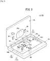
- the centrifugal separation device 14 is equipped with the centrifuge unit 18 having the rotor 18a, and a cassette mounting unit 78 configured in a manner so that the cassette 28 of the blood collection circuit set 12 is capable of being attached thereto.
- the cassette mounting unit 78 includes an attachment base 84 having a cassette mounting groove 82 formed therein, a lid 86 which can be opened and closed and is configured in a manner so as to cover the attachment base 84 when closed, a first load detecting unit 88 capable of pressing the first applied load measurement unit 60 (see FIG. 2 ) of the cassette 28, a second load detecting unit 90 capable of pressing the second applied load measurement unit 62 (see FIG. 2 ) of the cassette 28, and a plurality of clamps 72 configured to be capable of pressing the clamp action members 76 (see FIG. 2 ) of the cassette 28.
- a first port arrangement groove 84b into which the first port member 44 of the cassette 28 can be arranged, and a second port arrangement groove 84c into which the second port member 46 of the cassette 28 can be arranged are provided on the outer peripheral portion of the attachment base 84.
- the first port arrangement groove 84b and the second port arrangement groove 84c are in communication with the cassette mounting groove 82.
- the lid 86 is connected in a rotatable manner to the attachment base 84 via a hinge 85.
- the lid 86 When the lid 86 is closed with the cassette 28 being held in the cassette mounting groove 82 of the attachment base 84, the cassette 28 is sandwiched between the attachment base 84 and the lid 86.
- On the attachment base 84 and the lid 86 there are respectively provided concave portions 84a, 86a in which the filter accommodating unit 65 of the cassette 28 can be received. Consequently, the cassette 28 is appropriately retained between the attachment base 84 and the lid 86, while also preventing the filter accommodating unit 65 from being crushed. Further, the concave portions 84a, 86a prevent the filter accommodating unit 65 from bulging excessively.
- the first load detecting unit 88 is inserted into a first through hole 92a provided in the attachment base 84, together with being exposed in the cassette mounting groove 82. An upper surface of the first load detecting unit 88 protrudes from a bottom surface 82a of the cassette mounting groove 82.
- the second load detecting unit 90 is inserted into a second through hole 92b provided in a bottom surface 87 of the concave portion 84a, together with being exposed in the concave portion 84a. An upper surface of the second load detecting unit 90 protrudes from the bottom surface 87 of the concave portion 84a.
- the first load detecting unit 88 and the second load detecting unit 90 are constituted from load cells, for example.
- the plurality of clamps 72 (72a to 72c) are capable of being advanced and retracted in the thickness direction of the cassette 28 in a state in which the cassette 28 is retained in the cassette mounting groove 82, and are disposed corresponding to the arrangement of the plurality of clamp action members 76 (76a to 76c) provided on the cassette 28.
- the plurality of clamps 72 are capable of pressing the plurality of clamp action members 76, respectively, via a plurality of holes 94 that open on a bottom surface 82a of the cassette mounting groove 82. When closed, a plurality of projections 96 are provided on the lid 86 at positions corresponding to the plurality of holes 94 (clamps 72).
- the flow paths inside the clamp action members 76 are opened.
- the clamps 72 protrude from the holes 94 and press the clamp action members 76, the flow paths inside the clamp action members 76 are closed.
- the clamps 72 are retracted, due to the elastic restorative force of (the clamp action members 76 of) the cassette body 40, the clamp action members 76 are restored to their original shape, and the flow paths inside the clamp action members 76 are opened.
- the centrifugal separation device 14 includes an ACD solution transfer pump 98 which acts on the ACD solution transfer tube 23, and a collection and returning pump 100 which acts on the treatment unit side tube 34 that is connected to the cassette 28.
- the ACD solution transfer pump 98 is a pump that transfers the ACD solution from the ACD solution bag 24a to the cassette 28 and the blood treatment unit 16 via the ACD solution transfer tube 23.
- the collection and returning pump 100 is a pump for transferring the blood or blood components. Stated otherwise, the collection and returning pump 100 is a pump that transfers blood from the blood donor to the blood treatment unit 16, and together therewith, transfers the blood from the blood treatment unit 16 back to the blood donor.
- the ACD solution transfer pump 98 and the collection and returning pump 100 are constituted, for example, by a roller pump or a finger pump.
- the centrifugal separation device 14 further includes a control unit 102.
- the control unit 102 is a computation device including a microcomputer, and has a CPU (central processing unit), and a ROM, a RAM, etc., serving as memories, wherein by reading out and executing programs stored in the ROM, the CPU functions as various function realizing units (function realizing means).
- the various function realizing units may be constituted by function realizing devices in the form of hardware.
- the control unit 102 controls operations of the above-described plurality of clamps 72.
- the control unit 102 comprises a storage unit 104, a data acquisition unit 106, an estimated data calculation unit 108, a reaction force calculation unit 110, a first internal pressure calculation unit 112, a second internal pressure calculation unit 114, and a correction unit 116.
- the data acquisition unit 106 acquires initial data A (see FIG. 12 ) indicative of a temporal change in the reaction force of the first applied load measurement unit 60.
- the estimated data calculation unit 108 calculates estimated data B (see FIG. 12 ) for the purpose of estimating the reaction force of the first applied load measurement unit 60 during collection of the blood components.
- the reaction force calculation unit 110 calculates the reaction force of the first applied load measurement unit 60 based on the estimated data B.
- the first internal pressure calculation unit 112 calculates the internal pressure (circuit internal pressure) of the first applied load measurement unit 60 on the basis of the reaction force of the first applied load measurement unit 60 as calculated by the reaction force calculation unit 110, and the load detected by the first load detecting unit 88.
- the second internal pressure calculation unit 114 calculates the internal pressure of the second applied load measurement unit 62 on the basis of the load detected by the second load detecting unit 90.
- the correction unit 116 corrects the estimated data B (see FIG. 15 ) in a manner so that the internal pressure calculated by the first internal pressure calculation unit 112 becomes equivalent to the internal pressure calculated by the second internal pressure calculation unit 114, at a time between the collection operation and the returning operation, in a state in which an inner hole of the first applied load measurement unit 60 and an inner hole of the second applied load measurement unit 62 communicate with each other and the collection and returning pump 100 is stopped.
- the blood collection circuit set 12 is attached to the centrifugal separation device 14. More specifically, the cassette 28 is mounted in the cassette mounting unit 78, and the blood treatment unit 16 is attached to the rotor 18a. On the other hand, the blood collecting needle 20 pierces and is inserted into the blood donor.
- the cassette 28 is mounted in the cassette mounting unit 78, as shown in FIG. 4 , at first, the cassette 28 is mounted in the cassette mounting groove 82. In addition, by closing the lid 86, the cassette 28 is placed in a state of being held between the lid 86 and the attachment base 84. As a result, the first applied load measurement unit 60 and the second applied load measurement unit 62 of the cassette 28 are pressed respectively by the first load detecting unit 88 and the second load detecting unit 90, and are placed in a state of being slightly elastically deformed. Further, the plurality of clamp action members 76 of the cassette 28 are placed in facing relation with respect to the plurality of clamps 72.
- priming with the ACD solution is carried out. More specifically, at a stage at which it is detected by a non-illustrated line sensor disposed outside of the cassette 28 that the ACD solution has arrived in the immediate vicinity of the first port 43a, priming by the ACD solution is terminated.
- the centrifugal separation device 14 applies a centrifugal force to the blood treatment unit 16 that is attached to the rotor 18a, and together therewith, by operation of the collection and returning pump 100, blood (whole blood) from the blood donor is extracted and introduced into the blood treatment unit 16 (blood collection operation).
- blood whole blood
- the centrifugal force that accompanies rotation of the rotor 18a the blood introduced into the blood treatment unit 16 is separated into red blood cells (concentrated red blood cells), a buffy coat, and plasma (platelet poor plasma).
- the plasma that is separated in the blood treatment unit 16 is introduced into the PPP bag 24b via the PPP transfer tube 36.
- the remaining blood components (the red blood cells and the buffy coat) are returned to the blood donor (returning operation).
- the filter member 70 provided in the blood returning line 42b of the cassette 28 any risk of such foreign matter being returned to the blood donor can be reduced.
- the collection operation and the returning operation described above are performed a plurality of times.
- the clamps 72 (see FIG. 3 ) of the centrifugal separation device 14 are operated in the following manner.
- priming by the ACD solution is carried out, the clamps 72a, 72b, and 72c are opened.
- priming by the ACD solution is terminated at a stage at which it is detected by a non-illustrated line sensor outside the cassette 28 in the immediate vicinity of the first port 43a that the ACD solution has arrived in close proximity to the first port 43a.
- the clamp 72a is closed, and the clamps 72b and 72c are opened.
- the blood collection line 42a is closed, whereas the blood returning line 42b is opened. Accordingly, when the blood components pass through the filter member 70, clotted blood contained within the blood components is trapped in the filter member 70. Since the blood collection line 42a is closed, foreign matter cannot be returned to the blood donor via the blood collection line 42a.
- step S1 of FIG. 10 the control unit 102 determines whether or not the cassette 28 has been mounted in the cassette mounting unit 78. More specifically, the control unit 102 determines that the cassette 28 has been mounted in the cassette mounting unit 78 when the lid 86 is closed, in a state in which the cassette 28 is mounted in the cassette mounting groove 82 of the attachment base 84.
- step S1 determines that the cassette 28 is not mounted in the cassette mounting unit 78 (step S1: NO)
- the process remains at step S1 until it is determined that the cassette 28 has been mounted in the cassette mounting unit 78.
- step S2 determines that the cassette 28 has been mounted in the cassette mounting unit 78 (step S1: YES).
- step S2 the control unit 102 initiates measurement of an elapsed time period from when the control unit 102 determines that the cassette 28 has been mounted in the cassette mounting unit 78.
- step S3 the control unit 102 determines whether or not the elapsed time period has reached the predetermined time period t1 (see FIG. 12 ).
- the predetermined time period t1 can be arbitrarily set, the predetermined time period t1 may be set to five minutes, for example.
- step S3 determines that the elapsed time period has not reached the predetermined time period t1 (step S3: NO)
- the process remains at step S3 until it is determined that the elapsed time period has reached the predetermined time period t1.
- step S4 a data acquisition step is performed.
- the data acquisition unit 106 uses the load detected by the first load detecting unit 88 during a predetermined data acquisition time period t2, acquires the initial data A indicative of the temporal change in the reaction force of the first applied load measurement unit 60.
- the predetermined time period t2 can be arbitrarily set, the predetermined time period t2 may be set to five minutes, for example.
- an estimated data calculation step is performed.
- the estimated data calculation unit 108 calculates estimated data B (a baseline) for the purpose of estimating the reaction force of the first load detecting unit 88 that changes depending on the time period during which the blood components are collected. More specifically, the estimated data calculation unit 108 calculates the estimated data B using a least squares method based on the initial data A. Consequently, it is possible to obtain the reaction force of the first applied load measurement unit 60 in real time, which changes depending on the time period during which the blood components are collected.
- the calculated estimated data B is saved (stored) in the storage unit 104.
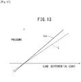
- the slope of the calibration curve L (see FIG. 13 ), which is data that is used for calculating the internal pressure, is corrected using the load detected by the second load detecting unit 90. Consequently, the calibration curve La, the slope of which has been corrected, is obtained.
- the calibration curve L can be acquired in advance by experiment or analysis.
- the second applied load measurement unit 62 is more easily deformed than the first applied load measurement unit 60, the relationship between the load detected by the second load detecting unit 90 and the pressure corresponding to the load is extremely stable. Accordingly, by using the second load detecting unit 90 as a reference sensor for the first load detecting unit 88, and thereby correcting the slope of the calibration curve L used when calculating the circuit internal pressure in the correction step, it is possible to measure the circuit internal pressure with high accuracy.
- the correction step may be performed (between step S2 and step S3) until the elapsed time period reaches the predetermined time period t1. In this case, it is possible to shorten the preparation time until blood component collection is started.
- step S7 of FIG. 10 the ACD solution transfer pump 98 is driven, and carries out the aforementioned priming in which the ACD solution is filled until immediately before the blood line 42 of the cassette 28. Thereafter, in step S8, blood is introduced into the blood line 42 of the cassette 28. Stated otherwise, the collection operation is started.
- step S9 of FIG. 11 the control unit 102 operates the collection and returning pump 100.
- the reaction force calculation unit 110 calculates the reaction force of the first applied load measurement unit 60 based on the estimated data B (see FIG. 12 ).
- the first internal pressure calculation unit 112 calculates a differential load, which is obtained by subtracting the reaction force calculated in the reaction force calculation step from the load detected by the first load detecting unit 88, and calculates the internal pressure (circuit internal pressure) of the first applied load measurement unit 60 on the basis of the differential load and the calibration curve La, the slope of which has been corrected.
- step S12 the control unit 102 determines whether or not operation of the collection and returning pump 100 has been stopped.
- the control unit 102 stops operation of the collection and returning pump 100 when a predetermined set time period has elapsed from when the collection operation or the returning operation was started. If it is determined by the control unit 102 that operation of the collection and returning pump 100 is not stopped (step S12: NO), the processing from step S10 and thereafter is performed.
- step S13 the control unit 102 determines whether or not it is immediately after the collection operation.
- step S13 the control unit 102 opens the clamps 72b and 72c (see FIG. 14 ). Consequently, the inner hole of the first applied load measurement unit 60 and the inner hole of the second applied load measurement unit 62 are placed in communication with each other. At this time, the internal pressure of the first applied load measurement unit 60 and the internal pressure of the second applied load measurement unit 62 both have the same pressure.
- the control unit 102 may also open the clamp 72a.
- the first internal pressure calculation unit 112 calculates the internal pressure of the first applied load measurement unit 60 on the basis of the load detected by the first load detecting unit 88 and the calibration curve La, the slope of which has been corrected.
- the second internal pressure calculation unit 114 calculates the internal pressure of the second applied load measurement unit 62 on the basis of the load detected by the second load detecting unit 90.
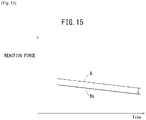
- step S17 the estimated data B is corrected in a manner so that the internal pressure calculated by the first internal pressure calculation unit 112 becomes equivalent to the internal pressure calculated by the second internal pressure calculation unit 114 (see FIG. 15 ).
- the corrected estimated data Ba is saved (stored) in the storage unit 104. Thereafter, the processing from step S9 and thereafter is performed.
- step S13 in the case it is determined by the control unit 102 that it is not immediately after the collection operation (that it is immediately after the returning operation) (step S13: NO), then in step S18, the control unit 102 determines whether or not the blood collection operation has ended. More specifically, in the event that the collection operation and the returning operation cycles have been performed a predetermined number of times, the control unit 102 determines that the collection of blood components has ended.
- step S18 NO
- the processing from step S15 and thereafter is performed.
- the process of step S14 need not necessarily be performed.
- the control unit 102 may open the clamp 72a before performing the process of step S15.
- step S18 the current execution of the flowchart is brought to an end.
- the blood component collection system 10 and the circuit internal pressure acquisition method according to the present embodiment exhibit the following effects.
- a load is detected by the first load detecting unit 88, which is the sum of the internal pressure (circuit internal pressure) of the blood collection line 42a through which the blood flows, and the reaction force of the first applied load measurement unit 60 (the restorative force accompanying deformation of the first applied load measurement unit 60). That is, in the case that the circuit internal pressure is a positive pressure, as shown in FIG. 16A , the load detected by the first load detecting unit 88 (the pressing force from the first applied load measurement unit 60) is obtained simply by adding the circuit internal pressure and the reaction force. On the other hand, in the case that the circuit internal pressure is a negative pressure, as shown in FIG. 16B , the load detected by the first load detecting unit 88 is obtained simply by subtracting the absolute value of the circuit internal pressure from the reaction force.
- the reaction force of the first applied load measurement unit 60 decreases over time.
- FIG. 17 an image is shown of a temporal change in the reaction force of the first applied load measurement unit 60, in the case that the reaction force of the first applied load measurement unit 60 when the cassette 28 is mounted in the cassette mounting unit 78 is set to zero.
- the reason that the reaction force of the first applied load measurement unit 60 decreases over time in the foregoing manner is due to the fact that creep is generated accompanying continuation of a state in which the first applied load measurement unit 60 is pressed by the first load detecting unit 88. Accordingly, when a fixed value that does not change over time is used as the reaction force of the first applied load measurement unit 60, the measurement accuracy of the internal pressure of the first applied load measurement unit 60 is lowered.
- the blood component collection system 10 is equipped with the data acquisition unit 106, the estimated data calculation unit 108, the reaction force calculation unit 110, and the first internal pressure calculation unit 112.
- the data acquisition unit 106 acquires the initial data A which is indicative of the temporal change in the reaction force of the first applied load measurement unit 60.
- the estimated data calculation unit 108 calculates the estimated data B for the purpose of estimating the reaction force of the first applied load measurement unit 60 during collection of the blood components.
- the reaction force calculation unit 110 calculates the reaction force of the first applied load measurement unit 60 based on the estimated data B.
- the first internal pressure calculation unit 112 calculates the internal pressure (circuit internal pressure) of the first applied load measurement unit 60 on the basis of the reaction force calculated by the reaction force calculation unit 110, and the load detected by the first load detecting unit 88. Consequently, since based on the estimated data B it is possible to calculate in real time the reaction force of the first applied load measurement unit 60 during collection of the blood components, which changes with the passage of time, it is possible for the circuit internal pressure to be accurately measured.
- the circuit internal pressure for example, ranges from -300 mmHg to 500 mmHg.
- the estimated data B is calculated by using the initial data A. Therefore, as time elapses, there is a possibility that the reaction force calculated using the estimated data B may deviate from the actual reaction force of the first applied load measurement unit 60.
- the blood component collection system 10 includes the correction unit 116 that corrects the estimated data B in a manner so that the internal pressure calculated by the first internal pressure calculation unit 112 becomes equivalent to the internal pressure calculated by the second internal pressure calculation unit 114, at a time between the collection operation and the returning operation, in a state in which the inner hole of the first applied load measurement unit 60 and the inner hole of the second applied load measurement unit 62 communicate with each other and the collection and returning pump 100 is stopped.
- the second internal pressure calculation unit 114 is capable of calculating relatively accurately the internal pressure (positive pressure) of the second applied load measurement unit 62.
- the first internal pressure calculation unit 112 is capable of calculating the internal pressure (positive pressure and negative pressure) of the first applied load measurement unit 60.
- the reaction force calculated using the estimated data B can be prevented from deviating from the actual reaction force of the first applied load measurement unit 60 as time elapses.
- the circuit internal pressure can be measured more accurately.
- the correction unit 116 corrects the estimated data B each time that the collection operation and the returning operation are switched. Consequently, it is possible to accurately measure the circuit internal pressure over the entire period of collection of biological liquid components (collection of blood components).
- the applied load measurement unit (first applied load measurement unit 60) undergoes creep deformation to a comparatively large extent, and therefore, the reaction force of the applied load measurement unit (first applied load measurement unit 60) easily fluctuates.
- the data acquisition unit 106 acquires the initial data A during the predetermined data acquisition time period t2 after the elapse of the predetermined time period t1 from when the biological component collection device (cassette 28) was mounted in the separation device (centrifugal separation device 14). Therefore, the accuracy of the estimated data B can be improved.
- the estimated data calculation unit 108 calculates the estimated data B using a least squares method based on the initial data A. Consequently, it is possible to easily calculate the estimated data B.
- the biological component collection device is not limited to being in the form of the cassette 28. Accordingly, the biological component collection device may be equipped with a first soft tube member having the blood collection line 42a, and a second soft tube member having the blood returning line 42b, and may be constituted in a manner so that both end portions of the first soft tube member and the second soft tube member are connected together respectively via connectors.
- the internal pressure calculation data which is used when calculating the circuit internal pressure using the load detected by the first load detecting unit 88 is not limited to the calibration curve L, but may be a table that is prepared beforehand.
- the first load detecting unit 88 and the second load detecting unit 90 may be configured in a manner so as to measure the load (in a non-contact manner) without applying pressure to the first applied load measurement unit 60 and the second applied load measurement unit 62.
- the scope of application of the present invention is not limited to a blood component collection system 10, but may be applied to various systems through which a liquid is made to flow through a flow path, for example, a whole blood donation system, or a culture apparatus for various types of cells which are collected or cultured from patients or donors, or alternatively, a medicinal solution administration system, or the like. Accordingly, the liquid that flows in the biological component collection device (biological component collection system) is not limited to blood.
- the biological component collection system and the circuit internal pressure acquisition method according to the present invention are not limited to the above-described embodiments, but the scope of the invention is defined by the claims.
Claims (5)
- System (10) zum Sammeln von biologischen Komponenten, das ausgestattet ist mit einer Trennvorrichtung (14), die angepasst ist, eine biologische Komponente von einer biologischen Flüssigkeit zu trennen, einer Sammelvorrichtung (28) für biologische Komponenten, die so konfiguriert ist, dass sie an der Trennvorrichtung (14) angebracht werden kann und eine darin ausgebildete Leitung (42) für biologische Flüssigkeit aufweist, durch die die biologische Flüssigkeit oder die biologische Komponente fließt, und eine Sammel- und Rückführpumpe (100), wobei das System (10) zum Sammeln von biologischen Komponenten so konfiguriert ist, dass es einen Sammelvorgang zum Sammeln einer gewünschten biologischen Komponente in der biologischen Flüssigkeit durchführt, indem es die biologische Flüssigkeit unter einer Tätigkeit der Sammel- und Rückführpumpe (100) von einem Spender durch die Leitung (42) für biologische Flüssigkeit zu der Trennvorrichtung (14) fließen lässt, und einen Rückführvorgang, um unter der Tätigkeit der Sammel- und Rückfuhrpumpe (100) verbleibende biologische Komponenten von der Trennvorrichtung (14) durch die Leitung (42) für biologische Flüssigkeit zu dem Spender zurückzuführen;wobei die Sammelvorrichtung (28) für biologische Komponenten aus einem weichen Material ausgebildet ist und ein Leitungsausbildungselement aufweist, das die Leitung (42) für biologische Flüssigkeit definiert;wobei die Trennvorrichtung (14) hat:eine erste Lasterfassungseinheit (88), die angepasst ist, eine Last zu erfassen, die auf eine erste Ausübungslastmesseinheit ausgeübt wird, die teilweise das Leitungsausbildungselement in einem in einer Vorrichtung installierten Zustand ausmacht, in der die Sammelvorrichtung (28) für biologische Komponenten an der Trennvorrichtung (14) angebracht ist;gekennzeichnet durcheine zweite Lasterfassungseinheit (90), die angepasst ist, eine auf eine zweite Ausübungslastmesseinheit (62) ausgeübte Last zu erfassen, die teilweise das Leitungsausbildungselement in dem in der Vorrichtung installierten Zustand ausbildet;eine Datenerfassungseinheit, die angepasst ist, um Anfangsdaten zu erfassen, die eine zeitliche Änderung in einer Reaktionskraft der ersten Ausübungslastmesseinheit unter Verwendung der durch die erste Lasterfassungseinheit (88) erfassten Last in dem in der Vorrichtung installierten Zustand anzuzeigen, bevor die biologische Flüssigkeit oder die biologische Komponente dazu gebracht wird, durch die Leitung (42) für biologische Flüssigkeit zum Sammeln der biologischen Komponente zu fließen;eine Einheit (108) zum Berechnen geschätzter Daten, die angepasst ist, um auf der Grundlage der Anfangsdaten geschätzte Daten zum Schätzen der Reaktionskraft der ersten Ausübungslastmesseinheit zu berechnen, die sich abhängig von der Zeit während des Sammelns der biologischen Komponente ändert;eine Reaktionskraftberechnungseinheit (110), die angepasst ist, während des Sammelns der biologischen Komponente die Reaktionskraft ausgehend von den geschätzten Daten zu berechnen;eine erste Innendruckberechnungseinheit (112), die angepasst ist einen Innendruck der ersten Ausübungslastmesseinheit ausgehend von der durch die Reaktionskraftberechnungseinheit (110) berechneten Reaktionskraft und ausgehend von der durch die erste Lasterfassungseinheit (88) erfassten Last zu berechnen;eine zweite Innendruckberechnungseinheit (114), die angepasst ist, einen Innendruck der zweiten Ausübungslastmesseinheit (62) ausgehend von der durch die zweite Lasterfassungseinheit (90) erfassten Last zu berechnen; undeine Korrektureinheit (116), die angepasst ist, die geschätzten Daten so in einer Weise zu korrigieren, dass der durch die erste Innendruckberechnungseinheit (112) berechnete Innendruck zu einer Zeit zwischen dem Sammelvorgang und dem Rückführvorgang in einem Zustand gleichwertig zu dem durch die zweite Innendruckberechnungseinheit (114) berechneten Innendruck wird, in dem ein inneres Loch der ersten Ausübungslastmesseinheit (60) und ein inneres Loch der zweiten Ausübungslastmesseinheit (62) miteinander in Verbindung sind und die Sammel- und Rückführpumpe (100) angehalten ist.
- System (10) zum Sammeln von biologischen Komponenten nach Anspruch 1, wobei die Korrektureinheit (116) die geschätzten Daten jedes Mal korrigiert, wenn der Sammelvorgang und der Rückführvorgang umgeschaltet werden.
- System (10) zum Sammeln von biologischen Komponenten nach Anspruch 1 oder 2, wobei die Datenerfassungseinheit die Anfangsdaten während eines vorbestimmten Datenerfassungszeitraums erfasst, nachdem ein vorbestimmter Zeitraum seit dann verstrichen ist, wenn die Vorrichtung (28) zum Sammeln von biologischen Komponenten in der Trennvorrichtung (14) montiert wurde.
- System (10) zum Sammeln von biologischen Komponenten nach einem der Ansprüche 1 bis 3, wobei die Schätzdatenberechnungseinheit (108) die geschätzten Daten unter Verwendung von zumindest einer Methode der kleinsten Quadrate ausgehend von den Anfangsdaten berechnet.
- Verfahren zum Erfassen eines Innendrucks unter Verwendung eines Systems (10) zum Sammeln von biologischen Komponenten, das mit einer Trennvorrichtung (14) ausgestattet ist, die angepasst ist, eine biologische Komponente von einer biologischen Flüssigkeit zu trennen, einer Vorrichtung (28) zu Sammeln von biologischen Komponenten, die konfiguriert ist, an der Trennvorrichtung (14) anbringbar zu sein, und eine darin ausgebildete Leitung (42) für biologische Flüssigkeit aufweist, durch die die biologische Flüssigkeit oder die biologische Komponente fließt, und eine Sammel- und Rückführpumpe (100), wobei das System (10) zum Sammeln von biologischen Komponenten geeignet zum Durchführen eines Sammelvorgangs zum Sammeln einer gewünschten biologischen Komponente in der biologischen Flüssigkeit ist, in dem es die biologische Flüssigkeit von einem Spender durch die Leitung (42) für biologische Flüssigkeit zu der Trennvorrichtung (14) und einer Tätigkeit der Sammel- und Rückführpumpe fließen lässt, und um unter der Tätigkeit der Sammel- und Rückführpumpe (100) einen Rückführvorgang zum Zurückführen der verbleibenden biologischen Komponenten von der Trennvorrichtung (14) durch die Leitung (42) für biologische Flüssigkeit zu dem Spender durchzuführen;wobei die Vorrichtung (28) zum Sammeln der biologischen Komponente aus einem weichen Material ausgebildet ist und ein Leitungsausbildungselement aufweist, das die Leitung (42) für biologische Flüssigkeit definiert;wobei die Trennvorrichtung (14) umfasst:eine erste Lasterfassungseinheit (88), die angepasst ist eine Last zu erfassen, die auf eine erste Ausübungslastmesseinheit (60) ausgeübt wird, die teilweise das Leitungsausbildungselement in einem in der Vorrichtung installierten Zustand ausmacht, in dem die Vorrichtung (28) zum Sammeln von biologischen Komponenten an der Trennvorrichtung (14) angebracht ist; undeiner zweiten Lasterfassungseinheit (90), die angepasst ist, eine Last zu erfassen, die auf eine zweite Ausübungslastmesseinheit (62) ausgeübt wird, die teilweise das Leitungsausbildungselement in dem in der Vorrichtung installierten Zustand ausmacht;dadurch gekennzeichnet, dass das Verfahren zum Erfassen des Innendrucks des Kreislaufs hat:einen Datenerfassungsschritt, Anfangsdaten zu erfassen, die eine zeitliche Änderung in einer Reaktionskraft der ersten Ausübungslastmesseinheit (60) unter der durch die erste Lasterfassungseinheit (88) erfassten Last in dem in der Vorrichtung installierten Zustand anzeigen, bevor dafür gesorgt wird, dass die biologische Flüssigkeit oder die biologische Komponente durch die Leitung (42) für biologische Flüssigkeit zur Sammlung der biologischen Komponente fließt;einen Schritt zum Berechnen geschätzter Daten, ausgehend von den Anfangsdaten geschätzte Daten zum Schätzen der Reaktionskraft der ersten Ausübungslastmesseinheit (60) zu berechnen, die sich abhängig von der Zeit während des Sammelns der biologischen Komponente ändert;einen Reaktionskraftberechnungsschritt, während des Sammelns der biologischen Komponente die Reaktionskraft ausgehend von den geschätzten Daten zu berechnen;einen ersten Innendruckberechnungsschritt, einen Innendruck der ersten Ausübungslastmesseinheit (60) ausgehend von der in dem Reaktionskraftberechnungsschritt berechneten Reaktionskraft und der durch die erste Lasterfassungseinheit (88) erfassten Last zu berechnen;einen zweiten Innendruckberechnungsschritt, einen Innendruck der zweiten Ausübungslastmesseinheit (62) ausgehend von der durch die zweite Lasterfassungseinheit (90) erfassten Last zu berechnen; undeinen Korrekturschritt, die geschätzten Daten in einer Weise so zu korrigieren, dass der in dem ersten Innendruckberechnungsschritt berechnete Innendruck zu einer Zeit zwischen dem Sammelvorgang und dem Rückführvorgang und in einem Zustand, in dem die Sammel- und Rückführpumpe (100) angehalten ist, gleichwertig zu dem in dem zweiten Innendruckberechnungsschritt berechneten Innendruck wird.
Applications Claiming Priority (2)
| Application Number | Priority Date | Filing Date | Title |
|---|---|---|---|
| JP2018206654 | 2018-11-01 | ||
| PCT/JP2019/041300 WO2020090544A1 (en) | 2018-11-01 | 2019-10-21 | Biological component collection system and circuit internal pressure acquisition method |
Publications (2)
| Publication Number | Publication Date |
|---|---|
| EP3860676A1 EP3860676A1 (de) | 2021-08-11 |
| EP3860676B1 true EP3860676B1 (de) | 2022-11-23 |
Family
ID=68501984
Family Applications (1)
| Application Number | Title | Priority Date | Filing Date |
|---|---|---|---|
| EP19801121.5A Active EP3860676B1 (de) | 2018-11-01 | 2019-10-21 | System zum sammeln biologischer komponenten und kreislaufinnendruckerfassungsverfahren |
Country Status (4)
| Country | Link |
|---|---|
| US (1) | US10758665B2 (de) |
| EP (1) | EP3860676B1 (de) |
| JP (1) | JP7355813B2 (de) |
| WO (1) | WO2020090544A1 (de) |
Families Citing this family (8)
| Publication number | Priority date | Publication date | Assignee | Title |
|---|---|---|---|---|
| WO2018230155A1 (en) * | 2017-06-16 | 2018-12-20 | Terumo Kabushiki Kaisha | Blood component collection cassette and method to measure the blood pressure inside the cassette |
| JP7261791B2 (ja) | 2017-09-28 | 2023-04-20 | テルモ株式会社 | 生体成分採取用デバイス、生体成分採取システム、及び生体成分採取システムの動作方法 |
| WO2019065812A1 (en) | 2017-09-28 | 2019-04-04 | Terumo Kabushiki Kaisha | SYSTEM FOR COLLECTING BIOLOGICAL CONSTITUENTS AND METHOD FOR ACQUIRING INTERNAL PRESSURE OF CIRCUIT |
| JP7303209B2 (ja) * | 2018-03-26 | 2023-07-04 | テルモ株式会社 | 生体成分採取システム及び生体成分採取システムの作動方法 |
| JP7203115B2 (ja) * | 2018-03-26 | 2023-01-12 | テルモ株式会社 | 生体成分採取システム及び生体成分採取システムの作動方法 |
| WO2020090544A1 (en) * | 2018-11-01 | 2020-05-07 | Terumo Kabushiki Kaisha | Biological component collection system and circuit internal pressure acquisition method |
| JP7355814B2 (ja) * | 2018-11-01 | 2023-10-03 | テルモ株式会社 | 生体成分採取システムおよび生体成分採取システムの作動方法 |
| WO2021050294A1 (en) * | 2019-09-10 | 2021-03-18 | Integrated Energy Services Corporation | System and method for assuring building air quality |
Family Cites Families (29)
| Publication number | Priority date | Publication date | Assignee | Title |
|---|---|---|---|---|
| JPS6036059A (ja) * | 1983-08-09 | 1985-02-25 | 東レ株式会社 | 血漿採取装置 |
| GB8521867D0 (en) * | 1985-09-03 | 1985-10-09 | Fisons Plc | Centrifuge |
| JP2581986B2 (ja) * | 1990-03-01 | 1997-02-19 | 鐘淵化学工業株式会社 | ピロー型圧力検出器 |
| DE4106444C1 (de) * | 1991-02-28 | 1992-07-23 | Fresenius Ag, 6380 Bad Homburg, De | |
| JPH08159896A (ja) * | 1994-12-09 | 1996-06-21 | Kanegafuchi Chem Ind Co Ltd | 軟質材を用いたピロー型圧力検出器 |
| WO1998022163A1 (en) * | 1996-11-22 | 1998-05-28 | Therakos, Inc. | Intergrated cassette for valving, pumping and controlling movement of fluids |
| US6280406B1 (en) * | 1997-09-12 | 2001-08-28 | Gambro, Inc | Extracorporeal blood processing system |
| DE19747254C2 (de) * | 1997-10-25 | 2000-01-13 | Gerhard Silber | Verfahren zur nichtinvasiven Innendruckmessung in elastischen Gefäßen |
| FR2817754B1 (fr) * | 2000-12-08 | 2003-09-12 | Hospal Internat Marketing Man | Dispositif pour la mesure de pression comportant une membrane moulee dans une cassette |
| AU2003300210A1 (en) * | 2002-12-30 | 2004-07-29 | James Brugger | Pressure detector for fluid circuits |
| DE102007000310A1 (de) * | 2007-06-05 | 2008-12-18 | Andreas Hettich Gmbh & Co. Kg | Einsatz und Zentrifuge mit Einsatz |
| US8591448B2 (en) * | 2009-05-13 | 2013-11-26 | Haemonetics Corporation | Pressure monitoring within a fluid cassette |
| CN102665792B (zh) | 2009-12-21 | 2016-01-20 | 泰尔茂比司特公司 | 用于提取血小板而具有减小的血浆遗留的方法及设备 |
| CN106104259B (zh) * | 2014-03-14 | 2018-11-09 | 泰尔茂株式会社 | 成分测定装置、方法以及存储介质 |
| EP3258980B1 (de) * | 2015-02-20 | 2020-03-18 | Terumo BCT, Inc. | Halter für verbundflüssigkeitsbeutelsystem |
| JP6715613B2 (ja) * | 2016-02-16 | 2020-07-01 | テルモ株式会社 | 血液成分採取用カセット及びその製造方法、並びに採血回路セット及び血液成分採取システム |
| US10413653B2 (en) * | 2016-04-08 | 2019-09-17 | Fenwal, Inc. | Fluid processing cassette and sensor coupling system and method |
| US11752243B2 (en) * | 2016-09-14 | 2023-09-12 | Terumo Kabushiki Kaisha | Blood component sampling cassette, blood sampling circuit set, and blood component sampling system |
| WO2018230545A1 (en) * | 2017-06-16 | 2018-12-20 | Terumo Kabushiki Kaisha | Blood component collection cassette with load detector and method to determine internal pressure |
| US11938256B2 (en) * | 2017-06-16 | 2024-03-26 | Terumo Kabushiki Kaisha | Blood component collection cassette having flow control features for pressure sensing |
| WO2018230155A1 (en) * | 2017-06-16 | 2018-12-20 | Terumo Kabushiki Kaisha | Blood component collection cassette and method to measure the blood pressure inside the cassette |
| EP3441094A1 (de) * | 2017-08-11 | 2019-02-13 | Fenwal, Inc. | Systeme und verfahren zur überwachung eines fluidprozesses mithilfe von hydrostatischem druck |
| JP7303209B2 (ja) * | 2018-03-26 | 2023-07-04 | テルモ株式会社 | 生体成分採取システム及び生体成分採取システムの作動方法 |
| WO2019188501A1 (en) * | 2018-03-26 | 2019-10-03 | Terumo Kabushiki Kaisha | Biological component treatment cassette and biological component treatment system |
| JP7203115B2 (ja) * | 2018-03-26 | 2023-01-12 | テルモ株式会社 | 生体成分採取システム及び生体成分採取システムの作動方法 |
| WO2019188500A1 (en) * | 2018-03-26 | 2019-10-03 | Terumo Kabushiki Kaisha | Biological component treatment cassette and biological component treatment system |
| EP3873558B1 (de) * | 2018-11-01 | 2023-03-08 | TERUMO Kabushiki Kaisha | System zum sammeln biologischer komponenten und kreislaufinnendruckerfassungsverfahren |
| WO2020090544A1 (en) * | 2018-11-01 | 2020-05-07 | Terumo Kabushiki Kaisha | Biological component collection system and circuit internal pressure acquisition method |
| JP7355814B2 (ja) * | 2018-11-01 | 2023-10-03 | テルモ株式会社 | 生体成分採取システムおよび生体成分採取システムの作動方法 |
-
2019
- 2019-10-21 WO PCT/JP2019/041300 patent/WO2020090544A1/en unknown
- 2019-10-21 EP EP19801121.5A patent/EP3860676B1/de active Active
- 2019-10-21 JP JP2021519914A patent/JP7355813B2/ja active Active
- 2019-10-30 US US16/668,750 patent/US10758665B2/en active Active
Also Published As
| Publication number | Publication date |
|---|---|
| US10758665B2 (en) | 2020-09-01 |
| JP7355813B2 (ja) | 2023-10-03 |
| US20200164136A1 (en) | 2020-05-28 |
| JP2022504749A (ja) | 2022-01-13 |
| EP3860676A1 (de) | 2021-08-11 |
| WO2020090544A1 (en) | 2020-05-07 |
Similar Documents
| Publication | Publication Date | Title |
|---|---|---|
| EP3860676B1 (de) | System zum sammeln biologischer komponenten und kreislaufinnendruckerfassungsverfahren | |
| EP3860677B1 (de) | System zum sammeln biologischer komponenten und kreislaufinnendruckerfassungsverfahren | |
| US10960128B2 (en) | Biological component collection system and circuit internal pressure acquisition method | |
| US10780212B2 (en) | Biological component collection system and flow path internal pressure acquisition method | |
| EP3768352B1 (de) | System zum sammeln biologischer komponenten und strömungsweginnendruckerfassungsverfahren | |
| EP3687594B1 (de) | System zum sammeln von biologischen komponenten und verfahren zum betrieb eines systems zum sammeln von biologischen komponenten | |
| US11925741B2 (en) | Biological component collection device with internal pressure sensor and method | |
| EP3687593B1 (de) | System zum sammeln biologischer komponenten und kreislaufinnendruckerfassungsverfahren | |
| US11786905B2 (en) | Blood component separation apparatus with internal pressure monitor |
Legal Events
| Date | Code | Title | Description |
|---|---|---|---|
| STAA | Information on the status of an ep patent application or granted ep patent |
Free format text: STATUS: UNKNOWN |
|
| STAA | Information on the status of an ep patent application or granted ep patent |
Free format text: STATUS: THE INTERNATIONAL PUBLICATION HAS BEEN MADE |
|
| PUAI | Public reference made under article 153(3) epc to a published international application that has entered the european phase |
Free format text: ORIGINAL CODE: 0009012 |
|
| STAA | Information on the status of an ep patent application or granted ep patent |
Free format text: STATUS: REQUEST FOR EXAMINATION WAS MADE |
|
| 17P | Request for examination filed |
Effective date: 20210504 |
|
| AK | Designated contracting states |
Kind code of ref document: A1 Designated state(s): AL AT BE BG CH CY CZ DE DK EE ES FI FR GB GR HR HU IE IS IT LI LT LU LV MC MK MT NL NO PL PT RO RS SE SI SK SM TR |
|
| DAV | Request for validation of the european patent (deleted) | ||
| DAX | Request for extension of the european patent (deleted) | ||
| GRAP | Despatch of communication of intention to grant a patent |
Free format text: ORIGINAL CODE: EPIDOSNIGR1 |
|
| STAA | Information on the status of an ep patent application or granted ep patent |
Free format text: STATUS: GRANT OF PATENT IS INTENDED |
|
| INTG | Intention to grant announced |
Effective date: 20220603 |
|
| GRAS | Grant fee paid |
Free format text: ORIGINAL CODE: EPIDOSNIGR3 |
|
| GRAA | (expected) grant |
Free format text: ORIGINAL CODE: 0009210 |
|
| STAA | Information on the status of an ep patent application or granted ep patent |
Free format text: STATUS: THE PATENT HAS BEEN GRANTED |
|
| AK | Designated contracting states |
Kind code of ref document: B1 Designated state(s): AL AT BE BG CH CY CZ DE DK EE ES FI FR GB GR HR HU IE IS IT LI LT LU LV MC MK MT NL NO PL PT RO RS SE SI SK SM TR |
|
| REG | Reference to a national code |
Ref country code: GB Ref legal event code: FG4D |
|
| REG | Reference to a national code |
Ref country code: CH Ref legal event code: EP |
|
| REG | Reference to a national code |
Ref country code: AT Ref legal event code: REF Ref document number: 1532746 Country of ref document: AT Kind code of ref document: T Effective date: 20221215 Ref country code: DE Ref legal event code: R096 Ref document number: 602019022311 Country of ref document: DE |
|
| REG | Reference to a national code |
Ref country code: IE Ref legal event code: FG4D |
|
| REG | Reference to a national code |
Ref country code: NL Ref legal event code: FP |
|
| REG | Reference to a national code |
Ref country code: LT Ref legal event code: MG9D |
|
| REG | Reference to a national code |
Ref country code: AT Ref legal event code: MK05 Ref document number: 1532746 Country of ref document: AT Kind code of ref document: T Effective date: 20221123 |
|
| PG25 | Lapsed in a contracting state [announced via postgrant information from national office to epo] |
Ref country code: SE Free format text: LAPSE BECAUSE OF FAILURE TO SUBMIT A TRANSLATION OF THE DESCRIPTION OR TO PAY THE FEE WITHIN THE PRESCRIBED TIME-LIMIT Effective date: 20221123 Ref country code: PT Free format text: LAPSE BECAUSE OF FAILURE TO SUBMIT A TRANSLATION OF THE DESCRIPTION OR TO PAY THE FEE WITHIN THE PRESCRIBED TIME-LIMIT Effective date: 20230323 Ref country code: NO Free format text: LAPSE BECAUSE OF FAILURE TO SUBMIT A TRANSLATION OF THE DESCRIPTION OR TO PAY THE FEE WITHIN THE PRESCRIBED TIME-LIMIT Effective date: 20230223 Ref country code: LT Free format text: LAPSE BECAUSE OF FAILURE TO SUBMIT A TRANSLATION OF THE DESCRIPTION OR TO PAY THE FEE WITHIN THE PRESCRIBED TIME-LIMIT Effective date: 20221123 Ref country code: FI Free format text: LAPSE BECAUSE OF FAILURE TO SUBMIT A TRANSLATION OF THE DESCRIPTION OR TO PAY THE FEE WITHIN THE PRESCRIBED TIME-LIMIT Effective date: 20221123 Ref country code: ES Free format text: LAPSE BECAUSE OF FAILURE TO SUBMIT A TRANSLATION OF THE DESCRIPTION OR TO PAY THE FEE WITHIN THE PRESCRIBED TIME-LIMIT Effective date: 20221123 Ref country code: AT Free format text: LAPSE BECAUSE OF FAILURE TO SUBMIT A TRANSLATION OF THE DESCRIPTION OR TO PAY THE FEE WITHIN THE PRESCRIBED TIME-LIMIT Effective date: 20221123 |
|
| PG25 | Lapsed in a contracting state [announced via postgrant information from national office to epo] |
Ref country code: RS Free format text: LAPSE BECAUSE OF FAILURE TO SUBMIT A TRANSLATION OF THE DESCRIPTION OR TO PAY THE FEE WITHIN THE PRESCRIBED TIME-LIMIT Effective date: 20221123 Ref country code: PL Free format text: LAPSE BECAUSE OF FAILURE TO SUBMIT A TRANSLATION OF THE DESCRIPTION OR TO PAY THE FEE WITHIN THE PRESCRIBED TIME-LIMIT Effective date: 20221123 Ref country code: LV Free format text: LAPSE BECAUSE OF FAILURE TO SUBMIT A TRANSLATION OF THE DESCRIPTION OR TO PAY THE FEE WITHIN THE PRESCRIBED TIME-LIMIT Effective date: 20221123 Ref country code: IS Free format text: LAPSE BECAUSE OF FAILURE TO SUBMIT A TRANSLATION OF THE DESCRIPTION OR TO PAY THE FEE WITHIN THE PRESCRIBED TIME-LIMIT Effective date: 20230323 Ref country code: HR Free format text: LAPSE BECAUSE OF FAILURE TO SUBMIT A TRANSLATION OF THE DESCRIPTION OR TO PAY THE FEE WITHIN THE PRESCRIBED TIME-LIMIT Effective date: 20221123 Ref country code: GR Free format text: LAPSE BECAUSE OF FAILURE TO SUBMIT A TRANSLATION OF THE DESCRIPTION OR TO PAY THE FEE WITHIN THE PRESCRIBED TIME-LIMIT Effective date: 20230224 |
|
| PG25 | Lapsed in a contracting state [announced via postgrant information from national office to epo] |
Ref country code: SM Free format text: LAPSE BECAUSE OF FAILURE TO SUBMIT A TRANSLATION OF THE DESCRIPTION OR TO PAY THE FEE WITHIN THE PRESCRIBED TIME-LIMIT Effective date: 20221123 Ref country code: RO Free format text: LAPSE BECAUSE OF FAILURE TO SUBMIT A TRANSLATION OF THE DESCRIPTION OR TO PAY THE FEE WITHIN THE PRESCRIBED TIME-LIMIT Effective date: 20221123 Ref country code: EE Free format text: LAPSE BECAUSE OF FAILURE TO SUBMIT A TRANSLATION OF THE DESCRIPTION OR TO PAY THE FEE WITHIN THE PRESCRIBED TIME-LIMIT Effective date: 20221123 Ref country code: DK Free format text: LAPSE BECAUSE OF FAILURE TO SUBMIT A TRANSLATION OF THE DESCRIPTION OR TO PAY THE FEE WITHIN THE PRESCRIBED TIME-LIMIT Effective date: 20221123 Ref country code: CZ Free format text: LAPSE BECAUSE OF FAILURE TO SUBMIT A TRANSLATION OF THE DESCRIPTION OR TO PAY THE FEE WITHIN THE PRESCRIBED TIME-LIMIT Effective date: 20221123 |
|
| REG | Reference to a national code |
Ref country code: DE Ref legal event code: R097 Ref document number: 602019022311 Country of ref document: DE |
|
| PG25 | Lapsed in a contracting state [announced via postgrant information from national office to epo] |
Ref country code: SK Free format text: LAPSE BECAUSE OF FAILURE TO SUBMIT A TRANSLATION OF THE DESCRIPTION OR TO PAY THE FEE WITHIN THE PRESCRIBED TIME-LIMIT Effective date: 20221123 Ref country code: AL Free format text: LAPSE BECAUSE OF FAILURE TO SUBMIT A TRANSLATION OF THE DESCRIPTION OR TO PAY THE FEE WITHIN THE PRESCRIBED TIME-LIMIT Effective date: 20221123 |
|
| PLBE | No opposition filed within time limit |
Free format text: ORIGINAL CODE: 0009261 |
|
| STAA | Information on the status of an ep patent application or granted ep patent |
Free format text: STATUS: NO OPPOSITION FILED WITHIN TIME LIMIT |
|
| PGFP | Annual fee paid to national office [announced via postgrant information from national office to epo] |
Ref country code: NL Payment date: 20230915 Year of fee payment: 5 Ref country code: GB Payment date: 20230831 Year of fee payment: 5 |
|
| 26N | No opposition filed |
Effective date: 20230824 |
|
| PG25 | Lapsed in a contracting state [announced via postgrant information from national office to epo] |
Ref country code: SI Free format text: LAPSE BECAUSE OF FAILURE TO SUBMIT A TRANSLATION OF THE DESCRIPTION OR TO PAY THE FEE WITHIN THE PRESCRIBED TIME-LIMIT Effective date: 20221123 |
|
| PGFP | Annual fee paid to national office [announced via postgrant information from national office to epo] |
Ref country code: FR Payment date: 20230911 Year of fee payment: 5 |
|
| PGFP | Annual fee paid to national office [announced via postgrant information from national office to epo] |
Ref country code: DE Payment date: 20230830 Year of fee payment: 5 |