EP3258015B1 - Bodenverdichtungsmaschine, sowie verfahren zum herstellen eines beschwerungsgewichtes für eine bodenverdichtungsmaschine - Google Patents
Bodenverdichtungsmaschine, sowie verfahren zum herstellen eines beschwerungsgewichtes für eine bodenverdichtungsmaschine Download PDFInfo
- Publication number
- EP3258015B1 EP3258015B1 EP17169222.1A EP17169222A EP3258015B1 EP 3258015 B1 EP3258015 B1 EP 3258015B1 EP 17169222 A EP17169222 A EP 17169222A EP 3258015 B1 EP3258015 B1 EP 3258015B1
- Authority
- EP
- European Patent Office
- Prior art keywords
- enclosure
- impact
- concrete core
- filling material
- machine frame
- Prior art date
- Legal status (The legal status is an assumption and is not a legal conclusion. Google has not performed a legal analysis and makes no representation as to the accuracy of the status listed.)
- Active
Links
Images


Classifications
-
- E—FIXED CONSTRUCTIONS
- E02—HYDRAULIC ENGINEERING; FOUNDATIONS; SOIL SHIFTING
- E02D—FOUNDATIONS; EXCAVATIONS; EMBANKMENTS; UNDERGROUND OR UNDERWATER STRUCTURES
- E02D3/00—Improving or preserving soil or rock, e.g. preserving permafrost soil
- E02D3/02—Improving by compacting
- E02D3/026—Improving by compacting by rolling with rollers usable only for or specially adapted for soil compaction, e.g. sheepsfoot rollers
-
- E—FIXED CONSTRUCTIONS
- E01—CONSTRUCTION OF ROADS, RAILWAYS, OR BRIDGES
- E01C—CONSTRUCTION OF, OR SURFACES FOR, ROADS, SPORTS GROUNDS, OR THE LIKE; MACHINES OR AUXILIARY TOOLS FOR CONSTRUCTION OR REPAIR
- E01C19/00—Machines, tools or auxiliary devices for preparing or distributing paving materials, for working the placed materials, or for forming, consolidating, or finishing the paving
- E01C19/22—Machines, tools or auxiliary devices for preparing or distributing paving materials, for working the placed materials, or for forming, consolidating, or finishing the paving for consolidating or finishing laid-down unset materials
- E01C19/23—Rollers therefor; Such rollers usable also for compacting soil
- E01C19/29—Rolling apparatus adapted to apply a rolling pressure less than its weight, e.g. roller finishers travelling on formrail combined with spread-out, strike-off or smoothing means; Rolling elements with controlled penetration or a controlled path of movement in a vertical plane, e.g. controlled by the formrails, by guides ensuring a desired configuration of the rolled surface
Definitions
- the invention relates to a soil compacting machine, in particular a compactor according to the preamble of claim 1, as well as a method for producing a weight for a soil compacting machine according to the preamble of claim 9.
- Such soil compacting machines are, for example, single drum rollers, as they are known in particular from the machine program of the company Hamm AG, Tirschenreuth.
- a known generic compactor has a wheel axle with wheels mounted in the machine frame, as well as at least one drum mounted in a front vehicle.
- the front end is connected to the machine frame via an articulated steering system.
- the machine frame also carries a body with a driver's cab and a hood.
- a weight weight adapted to the body is attached to the machine frame.
- This weight is a molded part made of concrete that can be painted to match the look of the body.
- the drum of such a roller train can also be a crusher drum with which a wide variety of building materials and minerals can be crushed and compacted at the same time.
- a bandage can be used as a rock breaker or for pre-breaking and relaxing of rocky ground and also as a padfoot roller.
- ballast system for soil compaction machines with two wheel axles which has modular ballast elements for adaptation to different compaction tasks, the number and arrangement of which can be selected selectively.
- the ballast elements consist of ballast boxes that are filled, for example, with bulk material, for example wet sand.
- the aim of this prior art is to use a modular ballast system to attach different weights to the machine frame in order to enable the static compaction load to be adapted to the compaction work to be performed.
- the generic single drum rollers mentioned at the beginning do not require such a variation in the weight load.
- the weights cast from concrete can, however, be easily damaged because the concrete is only slightly pressure-resistant, and larger pieces of concrete can break off and require repair and / or cleaning of the damaged floor surface, so that work interruptions until a replacement can be obtained. Soil compaction machine can occur. Because of the risk of the weight losing further fragments, the component has to be replaced, so that significant business interruptions can occur, especially if a spare part is not immediately available.
- the invention is therefore based on the object of specifying a soil compacting machine or a method for producing a weight for a soil compacting machine with which operational interruptions even in the event of damage to the weight while working on a soil surface the soil compacting machine and work interruptions at a construction site can be avoided.
- the invention provides in an advantageous manner that the at least one weighting weight at least partially has an impact-resistant casing which forms part of the body.
- the casing is filled with filler material, so that the impact-resistant casing protects the filler material from impact loads, even if it is not sufficiently pressure-resistant. Even in the event that a non-pressure-resistant filling material is damaged or broken, it is ensured that the weight is still fully functional due to the almost complete coating, so that no noteworthy operational or work interruptions can take place.
- the impact-resistant casing is therefore preferably made of a material with a high impact strength, which protects the weight and keeps it functional even in the event of a violent collision.
- the weight can be almost completely surrounded by the casing.
- the weighting weight is preferably attached to the rear end of the machine frame as a body part.
- the impact-resistant casing is filled with a weighting filler material, which preferably has a concrete core.
- the sheathing thus forms an impact-resistant outer skin for the concrete core and gives the entire weight the necessary pressure resistance and impact resistance.
- the anchoring of the fastening means in the concrete core has the advantage that the fastening of the weight is overall more stable on the machine frame and can absorb higher impact forces and shear loads.
- the concrete core has reinforcement structures.
- Such reinforcement structures can be two or three dimensional structures of a material with high tensile strength, e.g. Be metal that are introduced during the manufacture of the concrete core.
- the reinforcement structures can have three-dimensional lattice structures, for example.
- the casing has walls with inwardly protruding anchors which are connected to the concrete core.
- the anchorages can be connected to the concrete core or to the reinforcement structures contained therein, for example via wire brackets.
- the anchoring of the walls can extend into the concrete core. It goes without saying that the anchorages can also be in one piece with the walls of the casing.
- the impact-resistant casing has walls made of plastic material. Plastics with high tensile strengths and high impact strength values are preferred.
- the walls of the sheathing can have an incorporated reinforcement structure, wherein the walls can have a fiber-reinforced plastic, at least in some areas, or can be formed from fiber-reinforced plastic.
- the casing with walls made of plastic material can be painted and can also be formed from plastics that are multilayered and in particular already contain an outer layer of paint, so that subsequent painting can be dispensed with.
- the attachment means of the weight can be attached to the reinforcement structures of the concrete core.
- the weighting weight is formed from an impact-resistant casing which is adapted to the shape of the body and which is filled with weighting filling material.
- the weighting weight is at least partially, preferably predominantly, enclosed by the impact-resistant casing, which is used as a component of the body.
- the casing can be used as a casting mold for the concrete core, whereby the concrete core can be formed in the casing by filling in concrete that has not yet solidified.
- an already solidified, prefabricated concrete core adapted to the shape of the casing can be inserted into the casing.
- the sheathing is preferably made from an impact-resistant plastic or fiber-reinforced plastic.
- a gap between the casing and the concrete resulting from a shrinkage process or after the insertion of a prefabricated concrete core can be filled with adhesive or another possibly shock-absorbing filler.
- a reinforcement structure for the concrete to be filled can first be inserted into the impact-resistant casing, the reinforcement structure can be provided with fasteners for fastening to the machine frame before or after installation and then the solidifying filler material can be poured into the casing with the reinforcement structure inserted.
- anchors projecting inward from the walls of the casing are used, which are enclosed when the solidifying filler material is poured, whereby an intimate connection is formed between the walls of the casing and the solidified filler material after the filler material has solidified.
- Fig. 1 shows an example of a soil compacting machine in the form of a compactor 1.
- the machine frame 2 carries a body 4 with a driver's cab 5 and a hood 7, as well as two weighting weights 6 arranged on both sides of the longitudinal center line of the compactor 1 at the rear end 10 of the compactor 1.
- a wheel axle with wheels 9 is mounted in the machine frame 2 .
- a bandage 14 is mounted in a front carriage 12 connected to the machine frame 2 via an articulated joint.
- the bandage 14 can be a smooth bandage, but also a breaker bandage or a vibrating ramfoot bandage.
- weighting weights 6 described in more detail below can also be used for soil cultivation machines of other constructions, for example pneumatic tire rollers and the like. can be used, in which a weight 6 can be used as part of the body 4.
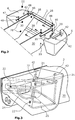
- Fig. 2 shows a perspective view of the arrangement and attachment of the weight weights 6 at the rear end 10 of the machine frame 2.
- the weighting weight 6 has an impact-resistant casing 8 which forms part of the body 4 and which receives a concrete core 16.
- the concrete core 16 preferably has reinforcement structures 20 that are integrated into the concrete core 16.
- the reinforcement structures 20 are made of Fig. 3 evident.
- the reinforcement structures 20 can be connected with fastening means 18 which are provided for fastening the weighting weight 6 to the machine frame 2. These fastening means 18 can be anchored on the casing 8 and / or in the concrete core 16. Screw connections are preferably used as fastening means 18.
- Fig. 3 shows an embodiment in which three threaded nuts 22 interacting with screw bolts 28 are fastened, in particular welded, to an anchor plate 24 as fastening means 18, wherein the anchor plate 24 can be connected to the reinforcement structures 20 integrated in the concrete core 16.
- the anchor plate 24 can be attached to the outside of the casing 8 on the side of the weight 6 facing the machine frame 2, or preferably in the concrete core 16, as shown in FIG Fig. 6 can be seen, be integrated, with corresponding recesses in the weight 6 allow the screw bolts 28 to be screwed into the threaded nuts 22.
- the weight 6 can be adjusted via the in Fig. 2 apparent screw bolts 28, which are inserted through through holes 29 in the side walls 30 of the machine frame 2, for example, are fastened to the machine frame 2.
- a plate 46 firmly connected to the machine frame 2 via screw bolts 48 can be attached to the top of the weight 6 Weighting weight 6 be screwed to relieve the bolt 28 of transverse forces.
- the casing 8 has walls 26 made of plastic material made of an impact-resistant and / or fiber-reinforced plastic.
- the walls made of plastic material form an impact-resistant casing 8 of the concrete core 16, so that the weight 6 can absorb high impact forces without any functional failure. Even if the concrete core 16 breaks in the event of a violent collision of the soil compacting machine, it is held together by the casing 8 of the concrete core 16, in particular in connection with the reinforcing structures 20, in such a way that no immediate business interruption and work interruptions are required.
- a damaged weight 6 can be exchanged after the work has been completed or if a corresponding replacement part is available.
- the casing 8 can also have an in Fig. 4 have shown removable lid 40, which can also cover a filling opening for concrete.
- the cover 40 does not have to extend over the entire upper surface of the casing 8 when the concrete core 16 is filled in in the liquefied state.
- fastening means 42 e.g. Threaded bushings which are connected to anchors 21 in the concrete core 16 may be arranged. These fastening means 42 allow lifting devices to be coupled in order to transport a weighting weight 6 or to hold it during assembly or disassembly.
- the plastic surface of the casing 8 also enables the weighting weight 6 to be painted as a component of the body 4, so that the weighting weight 6 also visually forms a body part.
- the sheath 8 can be made of impact-resistant or impact-resistant plastics, such as those from the overview "Technical plastics from Thyssen Krupp Plastics”: http://www.thyssenkruppplastics.de/fileadmin/inhalte/07_Publikationen/06_Pros pekte / 0750_Techn_Kunstscher_150dpi.pdf can be seen.
- suitable plastics with a tensile strength of, for example, over 40 N / mm 2 according to ISO 527 or plastics in which no breakage can be determined in an impact strength test according to ISO 179.
- thermoplastics, thermoplastic elastomers and thermosets are suitable plastics.
- a particularly impact-resistant plastic is, for example, polycarbonate.
- the wall thickness of the plastic walls can be calculated based on the strength values of the plastic and the impact load to be withstood.
- the wall thickness can also be based on the fact that the casing 8 cannot burst or excessively deform when it is filled with the filler material, in particular concrete.
- the casing 8 can also be supported from the outside when the concrete core 16 is poured, until the concrete core 16 has hardened.
- Figs. 4th and 6th show a schematic cross section through the weight 6 across the machine frame 2 with alternative anchors 32, 34.
- the anchoring 32 consists of a holder 36 which is integrated into the wall 26 and is connected to the schematically illustrated reinforcement structures 20 in the concrete core 16, for example, via at least one connecting bracket 38 which extends into the concrete core 16.
- Figs. 5a and 5b show the connecting bracket 38 and three-dimensionally an example of the holder 36.
- Fig. 6 shows an alternative embodiment in which an anchor 34, which can consist of a plastic or metal structure, is integrated into the wall 26 and protrudes into the concrete core 16.
- the anchorage 34 can have openings 44 in the area of the concrete core 16, through which concrete can pass and thus enables a particularly firm anchorage in the concrete core 16.
- This anchoring 34 is particularly advantageous if no wall of the casing 8 is provided on the side facing the machine frame 2.
- Fig. 6 an example of the arrangement of the anchor plate 24 in the concrete core 16 is also shown.
- the concrete core 16 preferably extends to the contact surface of the weight 6 on the machine frame 2, so that the concrete core 16 can be supported directly on the machine frame 2.
- the casing 8 is therefore at least partially recessed, so that the casing 8 does not completely surround the concrete core 16.
- the recesses simultaneously form the filling openings for filling in the not yet solidified concrete in the preferred method of manufacturing the weight weights 6.
- the sheathing 8 can also only be cut out in the areas in which the fastening means 18 pass through, for example in the form of the three screw bolts 28, so that the concrete core 16 is only flush with the casing 8 with a larger area on the machine frame in the vicinity of the fastening means 18 2 rests.
- the weighting weight 6 can then be almost completely encompassed by the casing 8.
Description
- Die Erfindung betrifft eine Bodenverdichtungsmaschine, insbesondere einen Walzenzug nach dem Oberbegriff des Anspruchs 1, sowie ein Verfahren zum Herstellen eines Beschwerungsgewichtes für eine Bodenverdichtungsmaschine nach dem Oberbegriff des Anspruchs 9.
- Derartige Bodenverdichtungsmaschinen sind beispielsweise Walzenzüge, wie sie insbesondere von dem Maschinenprogramm der Firma Hamm AG, Tirschenreuth bekannt sind.
- Ein bekannter gattungsgemäßer Walzenzug weist eine im Maschinenrahmen gelagerte Radachse mit Rädern auf, sowie mindestens eine in einem Vorderwagen gelagerte Bandage. Der Vorderwagen ist über eine Knicklenkung mit dem Maschinenrahmen verbunden. Der Maschinenrahmen trägt auch eine Karosserie mit einer Fahrerkabine sowie einer Motorhaube. Am hinteren Ende des Maschinenrahmens ist beiderseits einer Längsmittelachse des Maschinenrahmens ein an die Karosserie angepasstes Beschwerungsgewicht an dem Maschinenrahmen befestigt.
- Dieses Beschwerungsgewicht ist ein Formteil aus Beton, das zur optischen Anpassung an die Karosserie lackiert sein kann.
- Es versteht sich, dass die Bandage eines derartigen Walzenzuges auch eine Brecherbandage sein kann, mit der verschiedenste Bau- und Mineralstoffe gleichzeitig zerkleinert und verdichtet werden können. Eine derartige Bandage kann als Felsbrecher oder zum Vorbrechen und Entspannen von felsigem Untergrund und auch als Stampffußwalze verwendet werden.
- Aus der
WO 96/38631 - Dieser Stand der Technik zielt darauf ab, über ein modulares Ballastsystem unterschiedliche Gewichte an dem Maschinenrahmen zu befestigen, um eine Anpassung der statischen Verdichtungslast an die auszuführende Verdichtungstätigkeit zu ermöglichen.
- Die eingangs erwähnten gattungsgemäßen Walzenzüge benötigen eine derartige Variation der Gewichtsbelastung nicht. Die aus Beton gegossenen Beschwerungsgewichte können allerdings, da der Beton nur in geringem Umfang druckresistent ist, leicht beschädigt werden, wobei auch größere Betonstücke abbrechen können und eine Reparatur und/oder Reinigung der beschädigten Bodenoberfläche erfordern können, so dass Arbeitsunterbrechungen bis zur Beschaffung einer Ersatz-Bodenverdichtungsmaschine auftreten können. Wegen der Gefahr, dass das Beschwerungsgewicht noch weitere Bruchstücke verliert, ist ein Austausch des Bauteils erforderlich, so dass erhebliche Betriebsunterbrechungen auftreten können, insbesondere wenn ein Ersatzteil nicht sofort verfügbar ist.
- Der Erfindung liegt daher die Aufgabe zugrunde, eine Bodenverdichtungsmaschine bzw. ein Verfahren zum Herstellen eines Beschwerungsgewichtes für eine Bodenverdichtungsmaschine anzugeben, mit der auch im Falle einer Beschädigung des Beschwerungsgewichtes während der Bearbeitung einer Bodenoberfläche Betriebsunterbrechungen der Bodenverdichtungsmaschine und Arbeitsunterbrechung an einer Baustelle vermieden werden können.
- Zur Lösung dieser Aufgabe dienen die Merkmale der Ansprüche 1 bzw. 9.
- Die Erfindung sieht in vorteilhafter Weise vor, dass das mindestens eine Beschwerungsgewicht zumindest teilweise eine schlagfeste Ummantelung aufweist, die einen Bestandteil der Karosserie bildet. Die Ummantelung ist mit Füllmaterial ausgefüllt, so dass die schlagfeste Ummantelung das Füllmaterial, auch wenn es nicht ausreichend druckresistent ist, vor Stoßbelastungen schützt. Selbst für den Fall, dass ein nicht druckresistentes Füllmaterial beschädigt wird, oder zerbricht, ist sicherstellt, dass das Beschwerungsgewicht aufgrund der fast vollständigen Ummantelung weiterhin voll funktionsfähig ist, so dass keine nennenswerte Betriebs- oder Arbeitsunterbrechungen stattfinden können.
- Die schlagfeste Ummantelung besteht daher vorzugsweise aus einem Material mit einer hohen Schlagzähigkeit, die das Beschwerungsgewicht auch im Falle einer kräftigen Kollision schützt und funktionsfähig hält.
- Das Beschwerungsgewicht kann bis auf den Bereich der Befestigung am Maschinenrahmen nahezu vollständig von der Ummantelung umgeben sein.
- Das Beschwerungsgewicht ist vorzugsweise am hinteren Ende des Maschinenrahmens als Karosserieteil befestigt.
- Die schlagfeste Ummantelung ist mit einem beschwerenden Füllmaterial gefüllt, das vorzugsweise einen Betonkern aufweist. Die Ummantelung bildet dadurch eine schlagfeste Außenhaut für den Betonkern und verleiht dem gesamten Beschwerungsgewicht die erforderliche Druckresistenz und Stoßfestigkeit.
- Vorzugsweise ist vorgesehen, dass Befestigungsmittel an dem Beschwerungsgewicht zur Befestigung des Beschwerungsgewichts an dem Maschinenrahmen vorgesehen sind, welche in dem Betonkern verankert sind. Die Verankerung der Befestigungsmittel in dem Betonkern hat den Vorteil, dass die Befestigung des Beschwerungsgewichtes an dem Maschinenrahmen insgesamt stabiler ist und höhere Stoßkräfte und Scherbelastungen aufnehmen kann.
- Bei einem besonders bevorzugten Ausführungsbeispiel weist der Betonkern Verstärkungsstrukturen auf. Derartige Verstärkungsstrukturen können zwei- oder dreidimensionale Strukturen eines Materials mit hoher Zugfestigkeit, z.B. Metall sein, die bei der Herstellung des Betonkerns eingebracht werden. Dabei können die Verstärkungsstrukturen beispielsweise dreidimensionale Gitterstrukturen aufweisen.
- Bei einer Weiterbildung der Erfindung ist vorgesehen, dass die Ummantelung Wände mit nach innen hineinragenden Verankerungen aufweist, die mit dem Betonkern verbunden sind. Dabei können die Verankerungen beispielsweise über Drahtbügel mit dem Betonkern oder darin enthaltenen Verstärkungsstrukturen verbunden sein. Alternativ können die Verankerungen der Wände bis in den Betonkern hinein. Es versteht sich dabei, dass die Verankerungen auch einstückig mit den Wänden der Ummantelung sein können.
- Bei einem besonders bevorzugten Ausführungsbeispiel ist vorgesehen, dass die schlagfeste Ummantelung Wände aus Kunststoffmaterial aufweist. Dabei sind Kunststoffe mit hohen Zugfestigkeiten und hohen Schlagzähigkeitswerten bevorzugt.
- Die Wände der Ummaneltung können eine inkorporierte Verstärkungsstruktur aufweisen, wobei die Wände zumindest bereichsweise einen faserverstärkten Kunststoff aufweisen können, oder aus faserverstärktem Kunststoff gebildet sein können.
- Die Ummantelung mit Wänden aus Kunststoffmaterial ist lackierbar und kann auch aus Kunststoffen gebildet sein, die mehrschichtig sind und insbesondere bereits eine äußere Lackschicht enthalten, so dass eine nachträgliche Lackierung entfallen kann.
- Die Befestigungsmittel des Beschwerungsgewichts können an den Verstärkungsstrukturen des Betonkerns befestigt sein.
- Nach dem Verfahren zum Herstellen eines Beschwerungsgewichtes ist vorgesehen, dass das Beschwerungsgewicht aus einer schlagfesten, an die Form der Karosserie angepasste Ummantelung gebildet wird, die mit beschwerendem Füllmaterial gefüllt wird. Dabei ist das Beschwerungsgewicht zumindest teilweise, vorzugsweise überwiegend, von der schlagfesten Ummantelung eingefasst, die als Bestandteil der Karosserie verwendet wird.
- Die Ummantelung kann als Gießform für den Betonkern verwendet werden, wobei durch Einfüllen von noch nicht verfestigtem Beton der Betonkern in der Ummantelung geformt werden kann.
- Alternativ kann ein bereits verfestigter, vorgefertigter und der Form der Ummantelung angepasster Betonkern in die Ummantelung eingesetzt werden.
- Die Ummantelung wird vorzugsweise aus einem schlagzähen Kunststoff oder faserverstärkten Kunststoff hergestellt.
- Nach dem Einfüllen und Verfestigen des Betons kann ein sich aus einem Schrumpfungsprozess oder nach dem Einsetzen eines vorgefertigten Betonkerns ergebender Spalt zwischen der Ummantelung und dem Beton mit Kleber oder einem anderen ggf. stoßdämpfenden Füllmittel ausgefüllt werden.
- Zur Herstellung des Beschwerungsgewichtes kann zunächst eine Verstärkungsstruktur für den einzufüllenden Beton in die schlagfeste Ummantelung eingesetzt werden, die Verstärkungsstruktur vor oder nach dem Einbau mit Befestigungsmitteln zum Befestigen an dem Maschinenrahmen versehen werden und anschließend das sich verfestigende Füllmaterial in die Ummantelung mit eingesetzter Verstärkungsstruktur eingefüllt werden.
- Vorzugsweise ist vorgesehen, dass von den Wänden der Ummantelung nach innen abstehende Verankerungen verwendet werden, die beim Vergießen des sich verfestigenden Füllmaterials umschlossen werden, wodurch nach dem Verfestigen des Füllmaterial eine innige Verbindung zwischen den Wänden der Ummantelung und dem verfestigten Füllmaterial gebildet wird.
- Im Folgenden werden unter Bezugnahme auf die Zeichnungen Ausführungsbeispiele der Erfindung näher erläutert:
-
- Fig. 1
- eine Bodenverdichtungsmaschine in Form eines Walzenzuges,
- Fig. 2
- die Befestigung der Beschwerungsgewichte an dem Maschinenrahmen,
- Fig. 3
- die innere Struktur eines Betonkerns,
- Fig. 4
- ein schematischer Querschnitt durch das Beschwerungsgewicht,
- Fig. 5a
- ein in die Wand der Ummantelung integriertes Verankerungselement,
- Fig. 5b
- einen Verbindungsbügel, und
- Fig. 6
- ein alternatives Ausführungsbeispiel zu
Fig. 4 . -
Fig. 1 zeigt ein Beispiel einer Bodenverdichtungsmaschine in Form einer Walzenzuges 1. Der Maschinenrahmen 2 trägt eine Karosserie 4 mit einem Fahrerkabine 5 und einer Motorhaube 7, sowie zwei beiderseits der Längsmittellinie des Walzenzuges 1 am hinteren Ende 10 des Walzenzuges 1 angeordnete Beschwerungsgewichte 6. In dem Maschinenrahmen 2 ist eine Radachse mit Rädern 9 gelagert. In einem über eine Knicklenkung mit dem Maschinenrahmen 2 verbundenen Vorderwagen 12 ist eine Bandage 14 gelagert. - Die Bandage 14 kann eine Glattbandage sein, aber auch eine Brecherbandage oder eine Vibrationsstampffußbandage.
- Grundsätzlich können die im Folgenden näher beschriebenen Beschwerungsgewichte 6 auch für Bodenbearbeitungsmaschinen anderer Konstruktionen, z.B. Gummiradwalzen u.dgl. verwendet werden, bei denen ein Beschwerungsgewicht 6 als Bestandteil der Karosserie 4 zum Einsatz kommen kann.
-
Fig. 2 zeigt eine perspektivische Ansicht der Anordnung und Befestigung der Beschwerungsgewichte 6 am hinteren Ende 10 des Maschinenrahmen 2. - Das Beschwerungsgewicht 6 weist eine einen Bestandteil der Karosserie 4 bildenden, schlagfeste Ummantelung 8 auf, die einen Betonkern 16 aufnimmt. Der Betonkern 16 weist vorzugsweise Verstärkungsstrukturen 20 auf, die in den Betonkern 16 integriert sind. Die Verstärkungsstrukturen 20 sind aus
Fig. 3 ersichtlich. - Die Verstärkungsstrukturen 20 können mit Befestigungsmitteln 18 verbunden sein, die zur Befestigung des Beschwerungsgewichtes 6 an dem Maschinenrahmen 2 vorgesehen sind. Diese Befestigungsmittel 18 können an der Ummantelung 8 und/oder in dem Betonkern 16 verankert sein. Als Befestigungsmittel 18 werden vorzugsweise Schraubverbindungen verwendet.
-
Fig. 3 zeigt ein Ausführungsbeispiel, bei dem als Befestigungsmittel 18 drei mit Schraubbolzen 28 zusammenwirkende Gewindemuttern 22 auf einer Ankerplatte 24 befestigt, insbesondere verschweißt sind, wobei die Ankerplatte 24 mit den im Betonkern 16 integrierten Verstärkungsstrukturen 20 verbunden sein kann. Es versteht sich, dass die Gewindemuttern 22 von der Außenseite der Ummantelung 8 des Beschwerungsgewichtes 6 zugänglich sein müssen. Die Ankerplatte 24 kann dabei außen an der Ummantelung 8 an der dem Maschinenrahmen 2 zugewandten Seite des Beschwerungsgewichts 6 angebracht sein, oder vorzugsweise in dem Betonkern 16, wie ausFig. 6 ersichtlich, integriert sein, wobei entsprechende Aussparungen in dem Beschwerungsgewicht 6 das Einschrauben der Schraubbolzen 28 in die Gewindemuttern 22 ermöglichen. - Das Beschwerungsgewicht 6 kann über die in
Fig. 2 ersichtlichen Schraubbolzen 28, die z.B. durch Durchgangslöcher 29 in den Seitenwänden 30 des Maschinenrahmens 2 hindurch gesteckt werden, an dem Maschinenrahmen 2 befestigt werden. - Zusätzlich kann auf der Oberseite des Beschwerungsgewichtes 6 eine mit dem Maschinenrahmen 2 fest verbundene Platte 46 über Schraubbolzen 48 mit dem Beschwerungsgewicht 6 verschraubt sein, um die Schraubbolzen 28 von Querkräften zu entlasten.
- Die Ummantelung 8 hat Wände 26 aus Kunststoffmaterial aus einem schlagzähen und/oder faserverstärkten Kunststoff. Die Wände aus Kunststoffmaterial bilden eine schlagfeste Ummantelung 8 des Betonkerns 16, so dass das Beschwerungsgewicht 6 hohe Stoßkräfte ohne Funktionsausfall absorbieren kann. Selbst wenn bei einer kräftigen Kollision der Bodenverdichtungsmaschine der Betonkern 16 bricht, wird dieser durch die Ummantelung 8 des Betonkerns 16, insbesondere in Verbindung mit den Verstärkungsstrukturen 20, derart zusammengehalten, dass keine sofortige Betriebsunterbrechung und Arbeitsunterbrechungen erforderlich ist.
- Falls notwendig, kann ein beschädigtes Beschwerungsgewicht 6 dann nach Abschluss der Arbeiten, oder wenn ein entsprechendes Austauschteil vorliegt, ausgewechselt werden.
- Die Ummantelung 8 kann auch einen in
Fig. 4 gezeigten demontierbaren Deckel 40 aufweisen, der auch eine Einfüllöffnung für Beton bedecken kann. - Es versteht sich, dass der Deckel 40 sich nicht über die gesamte obere Fläche der Ummantelung 8 erstrecken muss, wenn der Betonkern 16 im verflüssigten Zustand einfüllt wird.
- Auf der Oberseite des Beschwerungsgewichts 6 können weitere Befestigungsmittel 42, z.B. Gewindebuchsen angeordnet sein, die mit Ankern 21 im Betonkern 16 verbunden sind. Diese Befestigungsmittel 42 erlauben, Hubeinrichtungen anzukoppeln, um ein Beschwerungsgewicht 6 zu transportieren, oder während der Montage oder Demontage zu halten.
- Die Kunststoffoberfläche der Ummantelung 8 ermöglicht auch eine Lackierung des Beschwerungsgewichts 6 als Bestandteil der Karosserie 4, so dass das Beschwerungsgewicht 6 auch optisch ein Karosserieteil bildet.
- Die Ummantelung 8 kann aus schlagfesten bzw. schlagzähen Kunststoffen hergestellt werden, wie sie beispielsweise aus dem Überblick "Technische Kunststoffe der Firma Thyssen Krupp Plastics":
http://www.thyssenkruppplastics.de/fileadmin/inhalte/07_Publikationen/06_Pros pekte/0750_Techn_Kunststoffe_150dpi.pdf
ersichtlich sind. Grundsätzlich geeignet sind Kunststoffe mit einer Zugfestigkeit von beispielsweise über 40 N/mm2 nach ISO 527 bzw. Kunststoffe, bei denen in einer Schlagzähigkeitsprüfung nach ISO 179 kein Bruch festgestellt werden kann. Grundsätzlich sind Thermoplaste, thermoplastische Elastomere und Duroplaste geeignete Kunststoffe. - Ein besonders schlagfester Kunststoff ist beispielsweise Polycarbonat.
- Die Wandstärke der Kunststoffwandungen kann anhand der Festigkeitswerte des Kunststoffs und der auszuhaltenden Stoßbelastung berechnet werden.
- Falls die Ummantelung 8 als Gießform verwendet wird, kann sich die Wandstärke auch daran orientieren, dass die Ummantelung 8 beim Einfüllen mit dem Füllmaterial, insbesondere Beton, nicht aufplatzen oder übermäßig verformen kann.
- Sind dünnere Wandstärken erwünscht, kann die Ummantelung 8 beim Vergießen des Betonkerns 16 auch von außen abgestützt werden, bis der Betonkern 16 ausgehärtet ist.
- Die
Fign. 4 und6 zeigen einen schematischen Querschnitt durch das Beschwerungsgewicht 6 quer zum Maschinenrahmen 2 mit alternativen Verankerungen 32, 34. - Bei dem Ausführungsbeispiel der
Fig. 4 besteht die Verankerung 32 aus einer Halterung 36, die in die Wand 26 integriert ist und z.B. über mindestens einen Verbindungsbügel 38, der in den Betonkern 16 hineinreicht, mit den schematisch dargestellten Verstärkungsstrukturen 20 im Betonkern 16 verbunden ist. - Die
Fign. 5a und 5b zeigen den Verbindungsbügel 38 und dreidimensional ein Beispiel für die Halterung 36. -
Fig. 6 zeigt eine alternative Ausführungsform, bei der eine Verankerung 34, die aus einer Kunststoff- oder Metallstruktur bestehen kann, in die Wand 26 integriert ist und in den Betonkern 16 hineinragt. Die Verankerung 34 kann dabei im Bereich des Betonkerns 16 Durchbrechungen 44 aufweisen, durch die Beton hindurchtreten kann und damit eine besonders feste Verankerung im Betonkern 16 ermöglicht. Diese Verankerung 34 ist besonders vorteilhaft, wenn auf der dem Maschinenrahmen 2 zugewandten Seite, keine Wand der Ummantelung 8 vorgesehen ist. - In
Fig. 6 ist zusätzlich ein Beispiel für die Anordnung der Ankerplatte 24 im Betonkern 16 gezeigt. Der Betonkern 16 reicht vorzugsweise bis an die Anlagefläche des Beschwerungsgewichtes 6 an dem Maschinenrahmen 2, so dass sich der Betonkern 16 direkt am Maschinenrahmen 2 abstützen kann. Auf der dem Maschinenrahmen 2 zugewandten Seite ist daher die Ummantelung 8 zumindest teilweise ausgespart, so dass die Ummantelung 8 den Betonkern 16 nicht vollständig umschließt. Die Aussparungen bilden dabei zugleich die Einfüllöffnungen zum Einfüllen des noch nicht verfestigten Betons bei der bevorzugten Herstellungsweise der Beschwerungsgewichte 6. - Es versteht sich, dass, bei dem Ausführungsbeispiel der
Fig. 4 , die Ummantelung 8 auch nur in den Bereichen, in denen die Befestigungsmittel 18 z.B. in Form der drei Schraubbolzen 28 hindurchtreten, ausgespart sein kann, so dass der Betonkern 16 nur im Umfeld der Befestigungsmittel 18 bündig mit der Ummantelung 8 mit einer größeren Fläche am Maschinenrahmen 2 aufliegt. Das Beschwerungsgewicht 6 kann dann nahezu vollständig von der Ummantelung 8 umfasst sein.
Claims (15)
- Bodenverdichtungsmaschine, insbesondere Walzenzug (1), mit einem Maschinenrahmen (2), der eine Karosserie (4) trägt, wobei mindestens ein an die Karosserie (4) angepasstes Beschwerungsgewicht (6) an dem Maschinenrahmen (2) befestigt ist,
dadurch gekennzeichnet,dass
das mindestens eine Beschwerungsgewicht (6) zumindest teilweise eine schlagfeste Ummantelung (8) aufweist, die einen Bestandteil der Karosserie (4) bildet, wobei die schlagfeste Ummantelung (8) mit beschwerendem Füllmaterial gefüllt ist und die schlagfeste Ummantelung (8) das Füllmaterial vor Stoßbelastungen schützt. - Bodenverdichtungsmaschine nach Anspruch 1, dadurch gekennzeichnet, dass das Beschwerungsgewicht (6) am hinteren Ende des Maschinenrahmens (2) befestigt ist.
- Bodenverdichtungsmaschine nach Anspruch 1, dadurch gekennzeichnet, dass das beschwerende Füllmaterial einen Betonkern (16) aufweist.
- Bodenverdichtungsmaschine nach Anspruch 3, dadurch gekennzeichnet, dass Befestigungsmittel (18) zur Befestigung des Beschwerungsgewichts (6) an dem Maschinenrahmen (2) vorgesehen sind, welche in dem Betonkern (16) verankert sind.
- Bodenverdichtungsmaschine einem der Ansprüche 3 oder 4, dadurch gekennzeichnet, dass der Betonkern (16) Verstärkungsstrukturen (20) aufweist.
- Bodenverdichtungsmaschine nach einem der Ansprüche 3 bis 5, dadurch gekennzeichnet, die Ummantelung (8) Wände (26) mit nach innen hineinragenden Verankerungen (32, 34) aufweist, die mit dem Betonkern (16) verbunden sind.
- Bodenverdichtungsmaschine nach Anspruch 1 bis 6, dadurch gekennzeichnet, dass die schlagfeste Ummantelung (8) Wände aus Kunststoffmaterial aufweist.
- Bodenverdichtungsmaschine nach Anspruch 7, dadurch gekennzeichnet, dass die Wände (26) der Ummantelung (8) eine inkorporierte Verstärkungsstruktur (20) aufweisen, wobei vorzugsweise die Wände (26) einen faserverstärkten Kunststoff aufweisen.
- Verfahren zum Herstellen eines Beschwerungsgewichtes (6) für eine Bodenverdichtungsmaschine, insbesondere für einen Walzenzug (1), mit einem eine Karosserie (4) tragenden Maschinenrahmen (2), wobei mindestens ein der Karosserie (4) angepasstes Beschwerungsgewicht (6) an dem Maschinenrahmen (2) befestigt wird,
dadurch gekennzeichnet, dass
das Beschwerungsgewicht (6) zumindest teilweise von einer schlagfesten, an die Form der Karosserie (4) angepasste Ummantelung (8) eingefasst wird, die als Bestandteil der Karosserie (4) verwendet wird. - Verfahren nach Anspruch 9, dadurch gekennzeichnet, dass als Füllmaterial ein Betonkern (16) mit integrierten Verstärkungsstrukturen (20) verwendet wird.
- Verfahren nach einem der Ansprüche 9 bis 10, dadurch gekennzeichnet, dass die den Betonkern (16) überwiegend umschließende Ummantelung (8) als Gießform für einen Betonkern (16) verwendet wird, wobei in der Ummantelung (8) durch Einfüllen von noch nicht verfestigtem Beton ein Betonkern (16) als beschwerendes Füllmaterial gebildet wird oder, dass ein bereits verfestigter der Ummantelung angepasster Betonkern (16) eingesetzt wird.
- Verfahren nach einem der Ansprüche 9 bis 11, dadurch gekennzeichnet, dass für die Wände (26) der schlagfesten Ummantelung (8) ein schlagzäher Kunststoff oder faserverstärkter Kunststoff verwendet wird.
- Verfahren nach einem der Ansprüche 9 bis 12, dadurch gekennzeichnet, dass die schlagfeste Ummantelung (8) an der Innenseite mit einer Klebeschicht versehen wird, bevor ein nachträglich sich verfestigendes Füllmaterial eingefüllt wird oder dass nach dem Einfüllen und Verfestigen des Füllmaterials ein sich aus einem Schrumpfungsprozess oder nach dem Einsetzen eines vorgefertigten Betonkerns (16) ergebender Spalt zwischen der Ummantelung (8) und dem Füllmaterial mit Kleber ausgefüllt wird.
- Verfahren nach einem der Ansprüche 9 bis 13, dadurch gekennzeichnet, dass zur Herstellung des Beschwerungsgewichtes (6) in die schlagfeste Ummantelung (8) zunächst eine Verstärkungsstruktur (20) für das Füllmaterial eingesetzt wird, die Verstärkungsstruktur (20) vor oder nach dem Einbau mit Befestigungsmitteln (18) zum Befestigen an dem Maschinenrahmen (2) versehen wird und dass anschließend das sich verfestigende Füllmaterial in die Ummantelung (8) mit eingesetzter Verstärkungsstruktur (20) eingefüllt wird.
- Verfahren nach einem der Ansprüche 9 bis 14, dadurch gekennzeichnet, dass von den Wänden (26) der Ummantelung (8) nach innen abstehende Verankerungen (32, 34) verwendet werden, die beim Vergießen des sich verfestigenden Füllmaterials umschlossen werden, wodurch nach dem Verfestigen des Füllmaterial eine starre Verbindung zwischen den Wänden (26) der Ummantelung (8) und dem verfestigten Füllmaterial gebildet wird.
Applications Claiming Priority (1)
| Application Number | Priority Date | Filing Date | Title |
|---|---|---|---|
| DE102016210906.5A DE102016210906A1 (de) | 2016-06-17 | 2016-06-17 | Bodenverdichtungsmaschine, sowie Verfahren zum Herstellen eines Beschwerungsgewichtes für eine Bodenverdichtungsmaschine |
Publications (2)
| Publication Number | Publication Date |
|---|---|
| EP3258015A1 EP3258015A1 (de) | 2017-12-20 |
| EP3258015B1 true EP3258015B1 (de) | 2020-09-02 |
Family
ID=58668789
Family Applications (1)
| Application Number | Title | Priority Date | Filing Date |
|---|---|---|---|
| EP17169222.1A Active EP3258015B1 (de) | 2016-06-17 | 2017-05-03 | Bodenverdichtungsmaschine, sowie verfahren zum herstellen eines beschwerungsgewichtes für eine bodenverdichtungsmaschine |
Country Status (3)
| Country | Link |
|---|---|
| EP (1) | EP3258015B1 (de) |
| CN (2) | CN107130499B (de) |
| DE (1) | DE102016210906A1 (de) |
Families Citing this family (1)
| Publication number | Priority date | Publication date | Assignee | Title |
|---|---|---|---|---|
| DE102016210906A1 (de) * | 2016-06-17 | 2017-12-21 | Hamm Ag | Bodenverdichtungsmaschine, sowie Verfahren zum Herstellen eines Beschwerungsgewichtes für eine Bodenverdichtungsmaschine |
Family Cites Families (8)
| Publication number | Priority date | Publication date | Assignee | Title |
|---|---|---|---|---|
| FR2133535B1 (de) * | 1971-04-15 | 1975-02-21 | Richier Sa | |
| BR9502171A (pt) | 1995-05-31 | 1997-08-26 | Dynapac Equipamentos Ind Ltda | Sistema de lastro para máquina de compactação |
| DE102004007389A1 (de) * | 2004-02-11 | 2005-09-15 | Ab-Polymerchemie Gmbh | Verfahren zum Herstellen eines Formteils aus Beton und/oder Mörtel mit einem zumindest bereichsweisen Oberflächenschutz und Verwendung desselben |
| WO2015122926A1 (en) * | 2014-02-17 | 2015-08-20 | Volvo Construction Equipment Ab | Pneumatic tire compactor with water ballast |
| DE102014216439A1 (de) * | 2014-08-19 | 2016-02-25 | Hamm Ag | Bodenverdichter |
| CN204059157U (zh) * | 2014-09-01 | 2014-12-31 | 常林股份有限公司 | 一种钢轮压路机的部件布置结构 |
| US9469947B2 (en) * | 2014-10-13 | 2016-10-18 | Caterpillar Paving Products Inc. | Modular compactor frame construction |
| DE102016210906A1 (de) * | 2016-06-17 | 2017-12-21 | Hamm Ag | Bodenverdichtungsmaschine, sowie Verfahren zum Herstellen eines Beschwerungsgewichtes für eine Bodenverdichtungsmaschine |
-
2016
- 2016-06-17 DE DE102016210906.5A patent/DE102016210906A1/de not_active Withdrawn
-
2017
- 2017-05-03 EP EP17169222.1A patent/EP3258015B1/de active Active
- 2017-06-13 CN CN201710442827.1A patent/CN107130499B/zh active Active
- 2017-06-13 CN CN201720682512.XU patent/CN208266639U/zh not_active Withdrawn - After Issue
Non-Patent Citations (1)
| Title |
|---|
| None * |
Also Published As
| Publication number | Publication date |
|---|---|
| CN107130499B (zh) | 2020-03-31 |
| EP3258015A1 (de) | 2017-12-20 |
| CN208266639U (zh) | 2018-12-21 |
| DE102016210906A1 (de) | 2017-12-21 |
| CN107130499A (zh) | 2017-09-05 |
Similar Documents
| Publication | Publication Date | Title |
|---|---|---|
| EP2499028B1 (de) | Modulare stossfängeranordnung für ein fahrzeug | |
| DE102005020917A1 (de) | Schutzplankenanordnung | |
| WO2019030054A1 (de) | Tragschiene für eine translativ verfahrbare roboterplattform | |
| EP3258015B1 (de) | Bodenverdichtungsmaschine, sowie verfahren zum herstellen eines beschwerungsgewichtes für eine bodenverdichtungsmaschine | |
| DE202017007035U1 (de) | Tragschiene für eine translativ verfahrbare Roboterplattform sowie Verfahrsystem und Robotersystem mit einer solchen Tragschiene | |
| EP2416933B1 (de) | Schalung für ein als bahnschwelle ausgestaltetes präzisions-betonteil | |
| EP2158363B1 (de) | Befülltes oder befüllbares fahrzeugrückhaltesystem zum begrenzen von fahrbahnen | |
| EP2025816B1 (de) | Verfahren zum Herstellen eines Wandelements und nach dem Verfahren hergestelltes Wandelement für eine Verkehrsleitwand | |
| EP1724416A2 (de) | Fundamentsysteme zum befestigen eines stab- oder pfostenförmigen gegenstandes im erdboden und hülsenartiges aufnahmeteil dafür | |
| EP2898158B1 (de) | Befestigungselement für eine sicherheitseinrichtung | |
| WO2016110293A2 (de) | Monolithisches betonprofil und herstellungsverfahren mittels gleitschalung | |
| DE102010029789A1 (de) | Frontträger für ein Kraftfahrzeug | |
| EP3702187B1 (de) | Aufprallschutzverstärkung einer fahrzeugkonstruktion sowie verbindungs- und herstellungsverfahren dafür | |
| DE102004010927B4 (de) | Verfahren und Vorrichtung zum Erstellen von insbesondere viertel-, halb- oder vollgewendelten Ortbeton-Treppen | |
| DE102017102568A1 (de) | Crash-System für Schienenfahrzeug | |
| EP3377228B1 (de) | Mahlschüssel | |
| EP3774691B1 (de) | Plattenkörper | |
| DE102005036881B4 (de) | Vorrichtung zum Erstellen einer Dehnfuge | |
| WO2015059008A1 (de) | Maschinentischfundament | |
| DE2315186A1 (de) | Stahlbetonstuetze | |
| DE3615490C2 (de) | Verfahren zum Verfestigen des Fußbereichs eines Ortbetonelementes in einer Bohrung und Vorrichtung zur Durchführung des Verfahrens | |
| EP3135819B1 (de) | Füllrohr und verfahren zum erstellen einer füllgutsäule im boden | |
| EP4294604A1 (de) | Fahrschiene für einen roboter und robotersystem mit einer solchen fahrschiene sowie verfahren zur herstellung einer solchen fahrschiene | |
| DE2310840A1 (de) | Schleisschutz-verfahren zu seiner herstellung und anwendung | |
| DE102019120406A1 (de) | Plattenkörper |
Legal Events
| Date | Code | Title | Description |
|---|---|---|---|
| PUAI | Public reference made under article 153(3) epc to a published international application that has entered the european phase |
Free format text: ORIGINAL CODE: 0009012 |
|
| STAA | Information on the status of an ep patent application or granted ep patent |
Free format text: STATUS: THE APPLICATION HAS BEEN PUBLISHED |
|
| STAA | Information on the status of an ep patent application or granted ep patent |
Free format text: STATUS: REQUEST FOR EXAMINATION WAS MADE |
|
| AK | Designated contracting states |
Kind code of ref document: A1 Designated state(s): AL AT BE BG CH CY CZ DE DK EE ES FI FR GB GR HR HU IE IS IT LI LT LU LV MC MK MT NL NO PL PT RO RS SE SI SK SM TR |
|
| AX | Request for extension of the european patent |
Extension state: BA ME |
|
| 17P | Request for examination filed |
Effective date: 20171207 |
|
| RBV | Designated contracting states (corrected) |
Designated state(s): AL AT BE BG CH CY CZ DE DK EE ES FI FR GB GR HR HU IE IS IT LI LT LU LV MC MK MT NL NO PL PT RO RS SE SI SK SM TR |
|
| GRAP | Despatch of communication of intention to grant a patent |
Free format text: ORIGINAL CODE: EPIDOSNIGR1 |
|
| STAA | Information on the status of an ep patent application or granted ep patent |
Free format text: STATUS: GRANT OF PATENT IS INTENDED |
|
| RIC1 | Information provided on ipc code assigned before grant |
Ipc: E02D 3/026 20060101AFI20180523BHEP |
|
| INTG | Intention to grant announced |
Effective date: 20180615 |
|
| TPAC | Observations filed by third parties |
Free format text: ORIGINAL CODE: EPIDOSNTIPA |
|
| GRAS | Grant fee paid |
Free format text: ORIGINAL CODE: EPIDOSNIGR3 |
|
| 17Q | First examination report despatched |
Effective date: 20181017 |
|
| GRAJ | Information related to disapproval of communication of intention to grant by the applicant or resumption of examination proceedings by the epo deleted |
Free format text: ORIGINAL CODE: EPIDOSDIGR1 |
|
| GRAL | Information related to payment of fee for publishing/printing deleted |
Free format text: ORIGINAL CODE: EPIDOSDIGR3 |
|
| STAA | Information on the status of an ep patent application or granted ep patent |
Free format text: STATUS: EXAMINATION IS IN PROGRESS |
|
| INTC | Intention to grant announced (deleted) | ||
| GRAP | Despatch of communication of intention to grant a patent |
Free format text: ORIGINAL CODE: EPIDOSNIGR1 |
|
| STAA | Information on the status of an ep patent application or granted ep patent |
Free format text: STATUS: GRANT OF PATENT IS INTENDED |
|
| INTG | Intention to grant announced |
Effective date: 20200409 |
|
| GRAS | Grant fee paid |
Free format text: ORIGINAL CODE: EPIDOSNIGR3 |
|
| GRAA | (expected) grant |
Free format text: ORIGINAL CODE: 0009210 |
|
| STAA | Information on the status of an ep patent application or granted ep patent |
Free format text: STATUS: THE PATENT HAS BEEN GRANTED |
|
| AK | Designated contracting states |
Kind code of ref document: B1 Designated state(s): AL AT BE BG CH CY CZ DE DK EE ES FI FR GB GR HR HU IE IS IT LI LT LU LV MC MK MT NL NO PL PT RO RS SE SI SK SM TR |
|
| REG | Reference to a national code |
Ref country code: GB Ref legal event code: FG4D Free format text: NOT ENGLISH |
|
| REG | Reference to a national code |
Ref country code: AT Ref legal event code: REF Ref document number: 1308936 Country of ref document: AT Kind code of ref document: T Effective date: 20200915 Ref country code: CH Ref legal event code: EP |
|
| REG | Reference to a national code |
Ref country code: DE Ref legal event code: R096 Ref document number: 502017006995 Country of ref document: DE |
|
| REG | Reference to a national code |
Ref country code: IE Ref legal event code: FG4D Free format text: LANGUAGE OF EP DOCUMENT: GERMAN |
|
| REG | Reference to a national code |
Ref country code: SE Ref legal event code: TRGR |
|
| REG | Reference to a national code |
Ref country code: LT Ref legal event code: MG4D |
|
| PG25 | Lapsed in a contracting state [announced via postgrant information from national office to epo] |
Ref country code: LT Free format text: LAPSE BECAUSE OF FAILURE TO SUBMIT A TRANSLATION OF THE DESCRIPTION OR TO PAY THE FEE WITHIN THE PRESCRIBED TIME-LIMIT Effective date: 20200902 Ref country code: FI Free format text: LAPSE BECAUSE OF FAILURE TO SUBMIT A TRANSLATION OF THE DESCRIPTION OR TO PAY THE FEE WITHIN THE PRESCRIBED TIME-LIMIT Effective date: 20200902 Ref country code: GR Free format text: LAPSE BECAUSE OF FAILURE TO SUBMIT A TRANSLATION OF THE DESCRIPTION OR TO PAY THE FEE WITHIN THE PRESCRIBED TIME-LIMIT Effective date: 20201203 Ref country code: NO Free format text: LAPSE BECAUSE OF FAILURE TO SUBMIT A TRANSLATION OF THE DESCRIPTION OR TO PAY THE FEE WITHIN THE PRESCRIBED TIME-LIMIT Effective date: 20201202 Ref country code: BG Free format text: LAPSE BECAUSE OF FAILURE TO SUBMIT A TRANSLATION OF THE DESCRIPTION OR TO PAY THE FEE WITHIN THE PRESCRIBED TIME-LIMIT Effective date: 20201202 Ref country code: HR Free format text: LAPSE BECAUSE OF FAILURE TO SUBMIT A TRANSLATION OF THE DESCRIPTION OR TO PAY THE FEE WITHIN THE PRESCRIBED TIME-LIMIT Effective date: 20200902 |
|
| REG | Reference to a national code |
Ref country code: NL Ref legal event code: MP Effective date: 20200902 |
|
| PG25 | Lapsed in a contracting state [announced via postgrant information from national office to epo] |
Ref country code: RS Free format text: LAPSE BECAUSE OF FAILURE TO SUBMIT A TRANSLATION OF THE DESCRIPTION OR TO PAY THE FEE WITHIN THE PRESCRIBED TIME-LIMIT Effective date: 20200902 Ref country code: PL Free format text: LAPSE BECAUSE OF FAILURE TO SUBMIT A TRANSLATION OF THE DESCRIPTION OR TO PAY THE FEE WITHIN THE PRESCRIBED TIME-LIMIT Effective date: 20200902 Ref country code: LV Free format text: LAPSE BECAUSE OF FAILURE TO SUBMIT A TRANSLATION OF THE DESCRIPTION OR TO PAY THE FEE WITHIN THE PRESCRIBED TIME-LIMIT Effective date: 20200902 |
|
| PG25 | Lapsed in a contracting state [announced via postgrant information from national office to epo] |
Ref country code: RO Free format text: LAPSE BECAUSE OF FAILURE TO SUBMIT A TRANSLATION OF THE DESCRIPTION OR TO PAY THE FEE WITHIN THE PRESCRIBED TIME-LIMIT Effective date: 20200902 Ref country code: PT Free format text: LAPSE BECAUSE OF FAILURE TO SUBMIT A TRANSLATION OF THE DESCRIPTION OR TO PAY THE FEE WITHIN THE PRESCRIBED TIME-LIMIT Effective date: 20210104 Ref country code: SM Free format text: LAPSE BECAUSE OF FAILURE TO SUBMIT A TRANSLATION OF THE DESCRIPTION OR TO PAY THE FEE WITHIN THE PRESCRIBED TIME-LIMIT Effective date: 20200902 Ref country code: EE Free format text: LAPSE BECAUSE OF FAILURE TO SUBMIT A TRANSLATION OF THE DESCRIPTION OR TO PAY THE FEE WITHIN THE PRESCRIBED TIME-LIMIT Effective date: 20200902 |
|
| PG25 | Lapsed in a contracting state [announced via postgrant information from national office to epo] |
Ref country code: AL Free format text: LAPSE BECAUSE OF FAILURE TO SUBMIT A TRANSLATION OF THE DESCRIPTION OR TO PAY THE FEE WITHIN THE PRESCRIBED TIME-LIMIT Effective date: 20200902 Ref country code: ES Free format text: LAPSE BECAUSE OF FAILURE TO SUBMIT A TRANSLATION OF THE DESCRIPTION OR TO PAY THE FEE WITHIN THE PRESCRIBED TIME-LIMIT Effective date: 20200902 Ref country code: IS Free format text: LAPSE BECAUSE OF FAILURE TO SUBMIT A TRANSLATION OF THE DESCRIPTION OR TO PAY THE FEE WITHIN THE PRESCRIBED TIME-LIMIT Effective date: 20210102 |
|
| REG | Reference to a national code |
Ref country code: DE Ref legal event code: R097 Ref document number: 502017006995 Country of ref document: DE |
|
| PG25 | Lapsed in a contracting state [announced via postgrant information from national office to epo] |
Ref country code: SK Free format text: LAPSE BECAUSE OF FAILURE TO SUBMIT A TRANSLATION OF THE DESCRIPTION OR TO PAY THE FEE WITHIN THE PRESCRIBED TIME-LIMIT Effective date: 20200902 |
|
| PLBE | No opposition filed within time limit |
Free format text: ORIGINAL CODE: 0009261 |
|
| STAA | Information on the status of an ep patent application or granted ep patent |
Free format text: STATUS: NO OPPOSITION FILED WITHIN TIME LIMIT |
|
| 26N | No opposition filed |
Effective date: 20210603 |
|
| PG25 | Lapsed in a contracting state [announced via postgrant information from national office to epo] |
Ref country code: DK Free format text: LAPSE BECAUSE OF FAILURE TO SUBMIT A TRANSLATION OF THE DESCRIPTION OR TO PAY THE FEE WITHIN THE PRESCRIBED TIME-LIMIT Effective date: 20200902 Ref country code: SI Free format text: LAPSE BECAUSE OF FAILURE TO SUBMIT A TRANSLATION OF THE DESCRIPTION OR TO PAY THE FEE WITHIN THE PRESCRIBED TIME-LIMIT Effective date: 20200902 |
|
| PG25 | Lapsed in a contracting state [announced via postgrant information from national office to epo] |
Ref country code: IT Free format text: LAPSE BECAUSE OF FAILURE TO SUBMIT A TRANSLATION OF THE DESCRIPTION OR TO PAY THE FEE WITHIN THE PRESCRIBED TIME-LIMIT Effective date: 20200902 |
|
| REG | Reference to a national code |
Ref country code: CH Ref legal event code: PL |
|
| GBPC | Gb: european patent ceased through non-payment of renewal fee |
Effective date: 20210503 |
|
| PG25 | Lapsed in a contracting state [announced via postgrant information from national office to epo] |
Ref country code: LI Free format text: LAPSE BECAUSE OF NON-PAYMENT OF DUE FEES Effective date: 20210531 Ref country code: MC Free format text: LAPSE BECAUSE OF FAILURE TO SUBMIT A TRANSLATION OF THE DESCRIPTION OR TO PAY THE FEE WITHIN THE PRESCRIBED TIME-LIMIT Effective date: 20200902 Ref country code: LU Free format text: LAPSE BECAUSE OF NON-PAYMENT OF DUE FEES Effective date: 20210503 Ref country code: CH Free format text: LAPSE BECAUSE OF NON-PAYMENT OF DUE FEES Effective date: 20210531 |
|
| REG | Reference to a national code |
Ref country code: BE Ref legal event code: MM Effective date: 20210531 |
|
| PG25 | Lapsed in a contracting state [announced via postgrant information from national office to epo] |
Ref country code: IE Free format text: LAPSE BECAUSE OF NON-PAYMENT OF DUE FEES Effective date: 20210503 Ref country code: GB Free format text: LAPSE BECAUSE OF NON-PAYMENT OF DUE FEES Effective date: 20210503 |
|
| PG25 | Lapsed in a contracting state [announced via postgrant information from national office to epo] |
Ref country code: FR Free format text: LAPSE BECAUSE OF NON-PAYMENT OF DUE FEES Effective date: 20210531 |
|
| PG25 | Lapsed in a contracting state [announced via postgrant information from national office to epo] |
Ref country code: BE Free format text: LAPSE BECAUSE OF NON-PAYMENT OF DUE FEES Effective date: 20210531 |
|
| PG25 | Lapsed in a contracting state [announced via postgrant information from national office to epo] |
Ref country code: HU Free format text: LAPSE BECAUSE OF FAILURE TO SUBMIT A TRANSLATION OF THE DESCRIPTION OR TO PAY THE FEE WITHIN THE PRESCRIBED TIME-LIMIT; INVALID AB INITIO Effective date: 20170503 |
|
| P01 | Opt-out of the competence of the unified patent court (upc) registered |
Effective date: 20230502 |
|
| PG25 | Lapsed in a contracting state [announced via postgrant information from national office to epo] |
Ref country code: NL Free format text: LAPSE BECAUSE OF NON-PAYMENT OF DUE FEES Effective date: 20200923 Ref country code: CY Free format text: LAPSE BECAUSE OF FAILURE TO SUBMIT A TRANSLATION OF THE DESCRIPTION OR TO PAY THE FEE WITHIN THE PRESCRIBED TIME-LIMIT Effective date: 20200902 |
|
| REG | Reference to a national code |
Ref country code: AT Ref legal event code: MM01 Ref document number: 1308936 Country of ref document: AT Kind code of ref document: T Effective date: 20220503 |
|
| PG25 | Lapsed in a contracting state [announced via postgrant information from national office to epo] |
Ref country code: AT Free format text: LAPSE BECAUSE OF NON-PAYMENT OF DUE FEES Effective date: 20220503 |
|
| PGFP | Annual fee paid to national office [announced via postgrant information from national office to epo] |
Ref country code: DE Payment date: 20230525 Year of fee payment: 7 Ref country code: CZ Payment date: 20230421 Year of fee payment: 7 |
|
| PGFP | Annual fee paid to national office [announced via postgrant information from national office to epo] |
Ref country code: SE Payment date: 20230522 Year of fee payment: 7 |