EP3257421A2 - Gebläsevorrichtung für einen staubsauger, verfahren zum betreiben einer gebläsevorrichtung, steuergerät und staubsauger - Google Patents
Gebläsevorrichtung für einen staubsauger, verfahren zum betreiben einer gebläsevorrichtung, steuergerät und staubsauger Download PDFInfo
- Publication number
- EP3257421A2 EP3257421A2 EP17170956.1A EP17170956A EP3257421A2 EP 3257421 A2 EP3257421 A2 EP 3257421A2 EP 17170956 A EP17170956 A EP 17170956A EP 3257421 A2 EP3257421 A2 EP 3257421A2
- Authority
- EP
- European Patent Office
- Prior art keywords
- blower
- engine
- motor
- bypass
- vacuum cleaner
- Prior art date
- Legal status (The legal status is an assumption and is not a legal conclusion. Google has not performed a legal analysis and makes no representation as to the accuracy of the status listed.)
- Granted
Links
Images


Classifications
-
- A—HUMAN NECESSITIES
- A47—FURNITURE; DOMESTIC ARTICLES OR APPLIANCES; COFFEE MILLS; SPICE MILLS; SUCTION CLEANERS IN GENERAL
- A47L—DOMESTIC WASHING OR CLEANING; SUCTION CLEANERS IN GENERAL
- A47L9/00—Details or accessories of suction cleaners, e.g. mechanical means for controlling the suction or for effecting pulsating action; Storing devices specially adapted to suction cleaners or parts thereof; Carrying-vehicles specially adapted for suction cleaners
- A47L9/28—Installation of the electric equipment, e.g. adaptation or attachment to the suction cleaner; Controlling suction cleaners by electric means
- A47L9/2805—Parameters or conditions being sensed
- A47L9/2831—Motor parameters, e.g. motor load or speed
-
- A—HUMAN NECESSITIES
- A47—FURNITURE; DOMESTIC ARTICLES OR APPLIANCES; COFFEE MILLS; SPICE MILLS; SUCTION CLEANERS IN GENERAL
- A47L—DOMESTIC WASHING OR CLEANING; SUCTION CLEANERS IN GENERAL
- A47L9/00—Details or accessories of suction cleaners, e.g. mechanical means for controlling the suction or for effecting pulsating action; Storing devices specially adapted to suction cleaners or parts thereof; Carrying-vehicles specially adapted for suction cleaners
- A47L9/0072—Mechanical means for controlling the suction or for effecting pulsating action
-
- A—HUMAN NECESSITIES
- A47—FURNITURE; DOMESTIC ARTICLES OR APPLIANCES; COFFEE MILLS; SPICE MILLS; SUCTION CLEANERS IN GENERAL
- A47L—DOMESTIC WASHING OR CLEANING; SUCTION CLEANERS IN GENERAL
- A47L9/00—Details or accessories of suction cleaners, e.g. mechanical means for controlling the suction or for effecting pulsating action; Storing devices specially adapted to suction cleaners or parts thereof; Carrying-vehicles specially adapted for suction cleaners
- A47L9/28—Installation of the electric equipment, e.g. adaptation or attachment to the suction cleaner; Controlling suction cleaners by electric means
- A47L9/2836—Installation of the electric equipment, e.g. adaptation or attachment to the suction cleaner; Controlling suction cleaners by electric means characterised by the parts which are controlled
-
- A—HUMAN NECESSITIES
- A47—FURNITURE; DOMESTIC ARTICLES OR APPLIANCES; COFFEE MILLS; SPICE MILLS; SUCTION CLEANERS IN GENERAL
- A47L—DOMESTIC WASHING OR CLEANING; SUCTION CLEANERS IN GENERAL
- A47L9/00—Details or accessories of suction cleaners, e.g. mechanical means for controlling the suction or for effecting pulsating action; Storing devices specially adapted to suction cleaners or parts thereof; Carrying-vehicles specially adapted for suction cleaners
- A47L9/28—Installation of the electric equipment, e.g. adaptation or attachment to the suction cleaner; Controlling suction cleaners by electric means
- A47L9/2889—Safety or protection devices or systems, e.g. for prevention of motor over-heating or for protection of the user
Definitions
- the invention relates to a blower device for a vacuum cleaner, a method for operating a blower device, a control device and a vacuum cleaner.
- a vacuum cleaner can be used for example in the household for cleaning a floor.
- the object of the invention is to provide an improved blower device for a vacuum cleaner, an improved method for operating a blower device, an improved control device and an improved vacuum cleaner.
- an aspirated airflow may be used to cool a blower motor of the vacuum cleaner by passing the airflow through the blower motor.
- blower motor If the blower motor is not operated at its maximum load, a lower cooling capacity is required than when the blower motor is operated at its maximum load.
- the cooling capacity can be regulated by the airflow directed by the blower motor. Airflow that is not required for cooling can be routed past the blower motor via a bypass.
- a variable bypass is arranged in a channel between the blower and the blower motor.
- the bypass is controlled by electronics.
- the achievable with the present invention consist in addition to a needs-based cooling performance for the blower motor in an increased efficiency of the overall system, since the bypass has a lower flow resistance, as the fan motor.
- a cleaning device Under a vacuum cleaner, a cleaning device can be understood in which air is sucked through a suction port of the vacuum cleaner.
- the required negative pressure can be generated using the fan motor and the blower.
- a blower motor can be understood to mean an electric motor.
- a fan may include a rotatable fan or turbine wheel and a fixed guide.
- An engine bypass may be an alternate way for a fan airflow past the fan motor.
- An adjusting element may for example be a slide for adjusting a flow cross-section of the engine bypass.
- the engine bypass may have at least one adjustable by the adjusting element bypass opening in an outflow channel of the fan. Positioning close to the fan allows air to flow through the engine bypass with little loss.
- the actuator may be movably mounted tangentially to a rotational axis of the fan.
- the adjusting element may have a gate which defines an opening cross section of the bypass opening. The slider can be moved with a rotary motion.
- the adjusting element can be mounted to be movable axially relative to the axis of rotation.
- An edge of the actuating element can define an opening cross section of the bypass opening. Due to the axial mobility, a simple motor for moving the actuator can be used.
- the adjusting element can be mounted to be movable radially relative to the axis of rotation.
- the actuator can be retracted and extended in the discharge channel.
- the adjusting element can be formed as a ramp, which closes the flow cross section of the engine bypass in a first position and releases a flow cross section of the outflow channel and releases the flow cross section of the engine bypass in a second position and closes a flow cross section of the outflow channel.
- the ramp can release the flow cross sections proportionally in intermediate positions.
- the actuator can be used as a controllable two-way valve.
- the air flow through the engine bypass can be set as a proportion of a total air flow.
- the blower device may comprise a controller according to the approach presented here.
- the control unit can be connected to a temperature sensor of the fan motor and a drive of the actuating element.
- the control unit can take over the control directly.
- a method for operating the blower device wherein in a step of providing a control signal for the actuator using a temperature of the blower motor representing temperature signal is provided to control a cooling air flow through the blower motor.
- the control signal may also be provided using a time signal representing a duration of use of the blower motor.
- a time signal representing a duration of use of the blower motor.
- control unit which is designed to execute, to control or to implement the steps of a variant of a method presented here in corresponding devices. Also by this embodiment of the invention in the form of a control device, the object underlying the invention can be achieved quickly and efficiently.
- the controller may be configured to read input signals and determine and provide output signals using the input signals.
- An input signal may represent, for example, a readable via an input interface of the controller sensor signal.
- An output signal may represent a control signal or a data signal that may be provided at an output interface of the controller.
- the controller may be configured to determine the output signals using a processing instruction implemented in hardware or software.
- the control device may comprise a logic circuit, an integrated circuit or a software module for this purpose, for example, be realized as a discrete component or be comprised by a discrete component.
- a corresponding vacuum cleaner has a said fan device and a said control unit, which is designed to provide the actuating signal via an interface to the actuating element of the fan device.
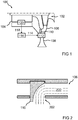
- FIG. 1 shows a representation of a blower device 100 for a vacuum cleaner according to an embodiment.
- the blower device 100 may be installed in a vacuum cleaner.
- one half of the blower device 100 is shown.
- the blower device 100 has a blower motor 104 coupled to a blower 102 of the blower device 100.
- An exhaust passage 106 of the blower 102 leads to an inflow port of the blower motor 104 to supply the blower motor 104 with a cooling air flow generated by the blower 102 in operation.
- the cooling air flow corresponds in the vacuum cleaner sucked by a filter device air.
- the cooling air flow flows through the blower motor 104 and cools the blower motor 104.
- an engine bypass 108 is arranged in the outflow passage 106.
- a flow cross-section of the engine bypass 108 is adjustable by a controllable actuator 110.
- the actuating element 110 is moved by a drive unit 112 in response to a control signal 114.
- the control signal 114 is provided by a controller 116 for operating the blower device 100.
- the controller 116 reads a temperature signal 118 representative of a temperature of the blower motor 104 from a temperature sensor 120 of the blower motor 104 and provides the control signal 114 as a function of temperature to control the cooling air flow through the blower motor 104.
- FIG. 1 a blower device 100 in the form of a vacuum cleaner fan.
- the blower device 100 is a combination of the blower motor 104 in the form of a prime mover or a motor, which converts the supplied electric power into a torque and a rotational speed and the designed as a working machine fan 102, the applied torque and speed in an aerodynamic vacuum a pressure difference and a flow converts.
- the overall efficiency of this unit is then composed of the product of the two prevailing individual efficiencies.
- the blower motor 104 of the blower device 100 is, for example, a high power density series-wound motor (RSM).
- the fan motor 104 is actively cooled, so that the power loss in the form of heat due to the high electrical input power is sufficiently dissipated. By the external cooling of the motor 104 is protected from destruction and the limits of the permissible winding temperatures are maintained.
- the airflow generated by the blower 102 is directed, according to one embodiment, through the interior of the blower motor 104 where the heat is taken up and removed by both the rotating armature and the stator surface.
- the described approach does not require continuous introduction of the full air flow generated by the blower 102 into the blower motor 104 to be cooled, which has the effect of increasing efficiency and efficiency.
- the flow flows through bottlenecks of the fan motor 104.
- the speed changes of the air flow leads to pressure fluctuations, turbulences and dead water areas, which further reduce the efficiency.
- Alone above the stator of the series motor (RSM) results in a static pressure loss of about 20 to 30 mbar.
- the introduced cooling air is not necessarily dependent on the suction air flow, since it does not always need to correspond to the suction air flow. If the dust bag fills or the vacuum cleaner hose is closed, the temperature and speed of the engine increases sharply. By a suitable control can be avoided that the available cooling air flow additionally reduced.
- a substantial increase in the overall efficiency of the blower unit can be achieved by the active control of the cooling air volume by the engine 104 presented here.
- the active material of the engine 104 can be better utilized in the adaptive thermal management presented here since it is not necessary to maintain reserves and worst case scenarios.
- the volume flow generated by the blower 102 can be completely passed through the engine 104. If, for example, due to lower performance requirements or increased motor efficiency, a complete flow through the motor 104 with the full volume flow is not or no longer completely required, bypasses 108 are activated in the blower housing. Due to the flow resistance of the motor 104, a portion of the generated volume flow is discharged through openings in front of the motor 104 from the housing 102. The total resistance of the blower unit drops.
- controllable engine bypass 108 presented here is structurally designed so that sufficient engine cooling is ensured even under adverse conditions, such as overvoltage, strong suction throttling, clogged filters or high power position.
- the engine bypass 108 is directly downstream of the blower 102, whereby a large part of the deflection losses in front of the engine can be avoided.
- the geometry is variable and allows for adjustments.
- the engine bypass 108 presented here can be optimized for many different types of fans.
- the cooling air flow supplied to the engine 104 and generated by the blower 102 is regulated, that is to say influenced by an active, adjusted or regulated mechanical control element 110.
- This can be achieved by a cross-sectionally variable, that is to say adjustable, bypass 108 or blow-out opening 108 arranged upstream of the motor housing.
- this bypass 108 is located either as a radial outlet in the fan shroud or as an axial outlet above or integrated within the diffuser, whereby the lossy, multiple flow deflections can be saved to the motor housing.
- a measurement or at least estimation of the current engine temperature is useful.
- the adjustment or regulation of the bypass opening 108 by means of adjustment of the bypass scenes 110 by means of adjustment of the bypass scenes 110.
- the known possibilities of adjustment such as rotary or translational for use via a solenoid 112, a motor 112 or bimetal come.
- the controller 116 can be taken over with the existing processor (MC) of the vacuum cleaner, for example as a P or PI controller.
- a temperature recording 120 can take place in the region of the winding overhang.
- FIG. 2 shows a representation of an arranged in an outflow 106 actuator 110 according to an embodiment.
- the actuating element 110 essentially corresponds to the actuating element in FIG. 1 ,
- the actuating element 110 here has the form of a ramp which is designed to deflect the cooling air flow 200 from the fan in a flow-favorable manner laterally.
- the actuating element 110 blocks the outflow channel completely when it is arranged in a completely extended position in the outflow channel.
- the cooling air flow 200 then flows through a recess 202 in Outflow 106 out.
- the ramp 110 is retracted, the fan operates at maximum efficiency.
- the outflow channel 106 and the actuator 110 are here substantially aligned as in FIG. 1 are shown.
- FIG. 3 shows a representation of an arranged in an outflow 106 actuator 110 according to an embodiment.
- the actuating element 110 essentially corresponds to the actuating element in FIG. 2 ,
- the actuator 110 is arranged here in a fully retracted position.
- the actuator 110 closes the recess 202 completely and the cooling air flow 200 flows along the completely released outflow channel 106 to the blower motor.
- the engine receives the maximum cooling capacity.
- the actuator 110 When the actuator 110 is disposed in an intermediate position, the discharge passage 106 and the recess 202 are partially released.
- the cooling air flow 200 is divided by the actuator 110. A part continues to flow to the fan motor and a part escapes through the recess 202 into the engine bypass.
- the ramps 110 are first moved out of the blower in the axial direction to the B-end shield during normal operation. They terminate the axial opening 202 flush and introduce the airflow 200 into the motor housing for cooling. If a maximum effect of the bypasses are allowed, the ramps 110 drive axially into the housing in the direction of the A-end shield and thereby close the radial air duct 106 to the motor and at the same time deflect the air 200 in the axial direction.
- the ramps 110 are immersed in the axial direction in the openings 202 of the pot in dependence on the determined motor temperature, in which case the bypass is maximum, or emerged, in which case the axial outlet 202 is blocked.
- the entire suction air 200 is then available as cooling air and is directed into the motor housing.
- FIG. 4 shows a sectional view of a blower 102 with an engine bypass 108 according to an embodiment.
- the blower 102 substantially corresponds to the blower in FIG FIG. 1 ,
- the blower 102 has a housing 400 in which a shaft 402 of the blower 102 is mounted.
- the housing 400 encloses a fan 404 of the blower 102.
- the housing 400 merges into the outflow channel 106.
- the housing 400 has along its circumference in the region of the outflow channel 106 or the hood a number of openings 202 or bypass window 202.
- the adjusting element 110 is arranged here as a slide ring around an outer side of the housing 400 and mounted axially displaceable relative to the shaft 402. About a position of Control element 110, an opening cross-section or an effective bypass area of the openings 202 is set.
- FIG. 5 shows an illustration of a blower device 100 with an engine bypass 108 according to an embodiment.
- the blower device 100 essentially corresponds to the blower device in FIG FIG. 4 ,
- the actuator 110 is arranged here so that the openings 202 are half closed. This means that only half the opening cross-section 500 is available for flowing through into the engine bypass 108.
- FIG. 6 shows a sectional view of a blower 102 with an engine bypass 108 according to an embodiment.
- the blower 102 substantially corresponds to the blower in the FIGS. 4 and 5 .
- the adjusting element 110 is rotatably mounted here on the housing 400.
- the actuator 110 has openings 600, which can be made to coincide with the openings 202 in the discharge channel. By a rotation of the actuating element 110, the resulting flow cross section can be adjusted.
- a bypass adjustment in the hood 400 is shown via a rotational adjustment.
- FIG. 7 shows an illustration of a blower device 100 with an engine bypass 108 according to an embodiment.
- the blower device 100 essentially corresponds to the representation in FIG FIG. 6 ,
- the adjusting element 110 is rotated relative to the openings 202, so that the openings 600 in the control element 110 cover the openings 202 only partially.
- the flow cross section 500 is reduced in the engine bypass 108.
- a rotary valve 110 is used on the fan shroud 400 to deflect the air regulated regulated or after closing in the engine for cooling.
- the ring 110 can block the passage window 202 in the hood 400 by, as in the FIGS. 4 and 5 immersed in the axial direction and the passage window 202 of the hood 400 in cross-section 500 reduced or as in the FIGS. 6 and 7 also has window 600 in the scope and by turning the cross-section 500 of the passage window 202 in the hood 400 decreases or closes.
- FIG. 8 is a flowchart of a method of operating a blower device according to one embodiment.
- the method can be used, for example, on the in FIG. 1 shown control unit to be executed.
- the method comprises a step 800 of providing in which an actuating signal to the actuator is provided using a temperature signal representative of a temperature of the fan motor to control a flow of cooling air through the fan motor.
- the method includes a step 802 of detecting and a step 804 of setting.
- step 802 of the detection the temperature of the fan motor is detected and mapped in the temperature signal.
- step (04 of setting the control signal is read and the actuator is set according to the control signal.
- thermal management of vacuum cleaner fans by means of active bypass control is proposed.
- a variable control of the air flow to the engine cooling in dependence of the engine temperature is proposed.
- the bypass When the vacuum cleaner is switched on when cold, the bypass is completely opened and the largest part of the blower air is discharged. As a result, the total resistance is the lowest, the overall efficiency maximum and the achievable dust absorption is greatest. After reaching a temperature threshold of the engine or, for example, after 10 minutes, the bypass is successively closed and the proportion of engine-passing cooling air is greater.
- the bypass can be completely closed. All air is then available to the engine as cooling air.
- the vacuum cleaner is switched on when hot, the power setting is set to MAX, the dust bag is full and a high pile carpet is sucked in, the bypasses can be fully closed so that all available airflow is routed through the engine and no cooling air through the bypass openings get lost.
Landscapes
- Engineering & Computer Science (AREA)
- Mechanical Engineering (AREA)
- Structures Of Non-Positive Displacement Pumps (AREA)
- Control Of Positive-Displacement Air Blowers (AREA)
Abstract
Description
- Die Erfindung betrifft eine Gebläsevorrichtung für einen Staubsauger, ein Verfahren zum Betreiben einer Gebläsevorrichtung, ein Steuergerät und einen Staubsauger.
- Ein Staubsauger kann beispielsweise im Haushalt zur Reinigung eines Bodens verwendet werden. Der Erfindung stellt sich die Aufgabe, eine verbesserte Gebläsevorrichtung für einen Staubsauger, ein verbessertes Verfahren zum Betreiben einer Gebläsevorrichtung, ein verbessertes Steuergerät und einen verbesserten Staubsauger bereitzustellen.
- Erfindungsgemäß wird diese Aufgabe durch eine Gebläsevorrichtung für einen Staubsauger, ein Verfahren zum Betreiben einer Gebläsevorrichtung, ein Steuergerät zum Betreiben einer Gebläsevorrichtung und einen Staubsager mit den Merkmalen der Hauptansprüche gelöst. Vorteilhafte Ausgestaltungen und Weiterbildungen der Erfindung ergeben sich aus den nachfolgenden Unteransprüchen.
- Bei einem Staubsauger kann ein angesaugter Luftstrom dazu verwendet werden, einen Gebläsemotor des Staubsaugers zu kühlen, indem der Luftstrom durch den Gebläsemotor geführt wird.
- Wenn der Gebläsemotor nicht mit seiner Maximallast betrieben wird, ist eine geringere Kühlleistung erforderlich, als wenn der Gebläsemotor mit seiner Maximallast betrieben wird. Die Kühlleistung kann über den durch den Gebläsemotor geleiteten Luftstrom reguliert werden. Nicht zum Kühlen erforderlicher Luftstrom kann über einen Bypass am Gebläsemotor vorbei geleitet werden.
- Bei dem hier vorgestellten Ansatz ist in einem Kanal zwischen dem Gebläse und dem Gebläsemotor ein variabler Bypass angeordnet. Der Bypass wird durch eine Elektronik angesteuert.
- Die mit der Erfindung erreichbaren Vorteile bestehen neben einer bedarfsgerechten Kühlleistung für den Gebläsemotor in einer erhöhten Effizienz des Gesamtsystems, da der Bypass einen geringeren Strömungswiderstand aufweist, als der Gebläsemotor.
- Es wird eine Gebläsevorrichtung für einen Staubsauger vorgestellt. Die Gebläsevorrichtung weist die folgenden Merkmale auf:
- einen Gebläsemotor, der mit einem Gebläse der Gebläsevorrichtung gekoppelt ist; und
- einen steuerbaren Motorbypass, der zwischen dem Gebläse und dem Gebläsemotor angeordnet ist, wobei der Motorbypass zumindest ein Stellelement zum Einstellen eines Strömungsquerschnitts des Motorbypasses aufweist.
- Unter einem Staubsauger kann ein Reinigungsgerät verstanden werden, bei dem Luft durch eine Ansaugöffnung des Staubsaugers eingesaugt wird. Der dazu erforderliche Unterdruck kann unter Verwendung des Gebläsemotors und des Gebläses erzeugt werden. Unter einem Gebläsemotor kann ein Elektromotor verstanden werden. Ein Gebläse kann ein drehbares Lüfterrad beziehungsweise Turbinenrad und eine feststehende Leiteinrichtung aufweisen. Ein Motorbypass kann ein alternativer Weg für einen Luftstrom des Gebläses an dem Gebläsemotor vorbei sein. Ein Stellelement kann beispielsweise ein Schieber zum Einstellen eines Strömungsquerschnitts des Motorbypasses sein.
- Der Motorbypass kann zumindest eine durch das Stellelement einstellbare Bypassöffnung in einem Ausströmkanal des Gebläses aufweisen. Durch eine Position nahe am Gebläse kann Luft mit geringen Verlusten durch den Motorbypass ausströmen.
- Das Stellelement kann tangential zu einer Rotationsachse des Gebläses beweglich gelagert sein. Das Stellelement kann eine Kulisse aufweisen, die einen Öffnungsquerschnitt der Bypassöffnung definiert. Der Schieber kann mit einer Drehbewegung bewegt werden.
- Das Stellelement kann axial zu der Rotationsachse beweglich gelagert sein. Eine Kante des Stellelements kann einen Öffnungsquerschnitt der Bypassöffnung definieren. Durch die axiale Beweglichkeit kann ein einfacher Motor zum Bewegen des Stellelements verwende werden.
- Das Stellelement kann radial zu der Rotationsachse beweglich gelagert sein. Das Stellelement kann in den Ausströmkanal eingefahren und ausgefahren werden.
- Das Stellelement kann als Rampe ausgeformt sein, die in einer ersten Position den Strömungsquerschnitt des Motorbypasses verschließt und einen Strömungsquerschnitt des Ausströmkanals freigibt und in einer zweiten Position den Strömungsquerschnitt des Motorbypasses freigibt und einen Strömungsquerschnitt des Ausströmkanals verschließt. Die Rampe kann in Zwischenpositionen die Strömungsquerschnitte anteilig freigeben. Das Stellelement kann so als regelbare Zweiwegearmatur verwendet werden. Der Luftstrom durch den Motorbypass kann als Anteil eines Gesamtluftstroms eingestellt werden.
- Die Gebläsevorrichtung kann ein Steuergerät gemäß dem hier vorgestellten Ansatz umfassen. Das Steuergerät kann mit einem Temperatursensor des Gebläsemotors und einem Antrieb des Stellelements verbunden sein. Das Steuergerät kann direkt die Regelung übernehmen.
- Weiterhin wird ein Verfahren zum Betreiben der Gebläsevorrichtung vorgestellt, wobei in einem Schritt des Bereitstellens ein Stellsignal für das Stellelement unter Verwendung eines eine Temperatur des Gebläsemotors repräsentierenden Temperatursignals bereitgestellt wird, um einen Kühlluftstrom durch den Gebläsemotor zu steuern.
- Das Stellsignal kann ferner unter Verwendung eines eine Benutzungsdauer des Gebläsemotor repräsentierenden Zeitsignals bereitgestellt werden. Durch das Verwenden der Benutzungsdauer kann basierend auf Erfahrungswerten der Kühlluftstrom für den Gebläsemotor eingestellt werden. So kann bereits präventiv gekühlt werden, bevor die Temperatur ansteigt.
- Der hier vorgestellte Ansatz schafft ferner ein Steuergerät, das ausgebildet ist, um die Schritte einer Variante eines hier vorgestellten Verfahrens in entsprechenden Einrichtungen durchzuführen, anzusteuern bzw. umzusetzen. Auch durch diese Ausführungsvariante der Erfindung in Form eines Steuergeräts kann die der Erfindung zugrunde liegende Aufgabe schnell und effizient gelöst werden.
- Das Steuergerät kann ausgebildet sein, um Eingangssignale einzulesen und unter Verwendung der Eingangssignale Ausgangssignale zu bestimmen und bereitzustellen. Ein Eingangssignal kann beispielsweise ein über eine Eingangsschnittstelle des Steuergeräts einlesbares Sensorsignal darstellen. Ein Ausgangssignal kann ein Steuersignal oder ein Datensignal darstellen, das an einer Ausgangsschnittstelle des Steuergeräts bereitgestellt werden kann. Das Steuergerät kann ausgebildet sein, um die Ausgangssignale unter Verwendung einer in Hardware oder Software umgesetzten Verarbeitungsvorschrift zu bestimmen. Beispielsweise kann das Steuergerät dazu eine Logikschaltung, einen integrierten Schaltkreis oder ein Softwaremodul umfassen und beispielsweise als ein diskretes Bauelement realisiert sein oder von einem diskreten Bauelement umfasst sein.
- Ein entsprechender Staubsauger weist eine genannte Gebläsevorrichtung und ein genanntes Steuergerät auf, das ausgebildet ist, um das Stellsignal über eine Schnittstelle an das Stellelement der Gebläsevorrichtung bereitzustellen. Auf diese Weise kann der beschriebene Ansatz vorteilhaft bei einem Staubsauger eingesetzt werden.
- Ein Ausführungsbeispiel der Erfindung ist in den Zeichnungen rein schematisch dargestellt und wird nachfolgend näher beschrieben. Es zeigt
- Figur 1
- eine Darstellung einer Gebläsevorrichtung für einen Staubsauger gemäß einem Ausführungsbeispiel;
- Figur 2
- eine Darstellung eines in einem Ausströmkanal angeordneten Stellelements gemäß einem Ausführungsbeispiel;
- Figur 3
- eine Darstellung eines in einem Ausströmkanal angeordneten Stellelements gemäß einem Ausführungsbeispiel;
- Figur 4
- eine Schnittdarstellung eines Gebläses mit einem Motorbypass gemäß einem Ausführungsbeispiel;
- Figur 5
- eine Darstellung einer Gebläsevorrichtung mit einem Motorbypass gemäß einem Ausführungsbeispiel;
- Figur 6
- eine Schnittdarstellung eines Gebläses mit einem Motorbypass gemäß einem Ausführungsbeispiel;
- Figur 7
- eine Darstellung einer Gebläsevorrichtung mit einem Motorbypass gemäß einem Ausführungsbeispiel; und
- Figur 8
- ein Ablaufdiagramm eines Verfahrens zum Betreiben einer Gebläsevorrichtung gemäß einem Ausführungsbeispiel.
-
Figur 1 zeigt eine Darstellung einer Gebläsevorrichtung 100 für einen Staubsauger gemäß einem Ausführungsbeispiel. Im betriebsbereiten Zustand kann die Gebläsevorrichtung 100 in einem Staubsauger verbaut sein. Dabei ist eine Hälfte der Gebläsevorrichtung 100 dargestellt. Die Gebläsevorrichtung 100 weist einen mit einem Gebläse 102 der Gebläsevorrichtung 100 gekoppelten Gebläsemotor 104 auf. Ein Ausströmkanal 106 des Gebläses 102 führt zu einer Einströmöffnung des Gebläsemotors 104, um dem Gebläsemotor 104 einen von dem Gebläse 102 im Betrieb erzeugten Kühlluftstrom zuzuführen. Der Kühlluftstrom entspricht im Staubsauger der durch eine Filtereinrichtung angesaugten Luft. Der Kühlluftstrom durchströmt den Gebläsemotor 104 und kühlt den Gebläsemotor 104. In dem Ausströmkanal 106 ist ein Motorbypass 108 angeordnet. Ein Strömungsquerschnitt des Motorbypasses 108 ist durch ein steuerbares Stellelement 110 einstellbar. Das Stellelement 110 wird von einer Antriebseinheit 112 ansprechend auf ein Stellsignal 114 bewegt. - Das Stellsignal 114 wird von einem Steuergerät 116 zum Betreiben der Gebläsevorrichtung 100 bereitgestellt. Das Steuergerät 116 liest ein eine Temperatur des Gebläsemotors 104 repräsentierendes Temperatursignal 118 von einem Temperatursensor 120 des Gebläsemotors 104 ein und stellt das Stellsignal 114 in Abhängigkeit von der Temperatur bereit, um den Kühlluftstrom durch den Gebläsemotor 104 zu steuern.
- Mit anderen Worten zeigt
Figur 1 eine Gebläsevorrichtung 100 in Form eines Staubsaugergebläses. Die Gebläsevorrichtung 100 ist eine Kombination des Gebläsemotors 104 in Form einer Antriebsmaschine beziehungsweise eines Motors, welcher die zugeführte elektrische Leistung in ein Drehmoment und eine Drehzahl wandelt und dem als eine Arbeitsmaschine ausgeführten Gebläse 102, das das anliegende Drehmoment und die Drehzahl in einen aerodynamischen Unterdruck beziehungsweise eine Druckdifferenz und einen Durchfluss wandelt. Der Gesamtwirkungsgrad dieser Einheit setzt sich dann aus dem Produkt der beiden jeweils vorherrschenden Einzelwirkungsgrade zusammen. - Der Gebläsemotor 104 der Gebläsevorrichtung 100 ist beispielsweise ein Reihenschlussmotor (RSM) mit hoher Leistungsdichte. Der Gebläsemotor 104 wird aktiv gekühlt, damit die Verlustleistung in Form von Wärme aufgrund der hohen elektrischen Eingangsleistung ausreichend abgeführt wird. Durch die Fremdkühlung wird der Motor 104 vor Zerstörung geschützt und die Grenzen der zulässigen Wicklungstemperaturen werden eingehalten.
- Der durch das Gebläse 102 erzeugte Luftstrom wird gemäß einem Ausführungsbeispiel durch das Innere des Gebläsemotors 104 geleitet, wo die Wärme sowohl vom rotierenden Anker als auch von der Statoroberfläche aufgenommen und abtransportiert wird.
- Durch den beschriebenen Ansatz ist keine ständige Einleitung der vollständigen durch das Gebläse 102 erzeugten Luftströmung in den zu kühlenden Gebläsemotor 104 erforderlich, was sich als effizient und wirkungsgradsteigernd auswirkt. Die ergibt sich dadurch, dass der durch den Gebläsemotor 104 geleitete erhebliche Volumenstrom mit seiner hohen Strömungsgeschwindigkeit innerhalb kleiner geometrischer Abmessungen mehrfach seine Strömungsrichtung ändert. Bei jeder Änderung der Strömungsrichtung wirkt ein induzierter Strömungswiderstand, der zu einem Druckverlust führt. Die Strömung strömt dabei durch Engstellen des Gebläsemotors 104. Durch die Geschwindigkeitsänderungen der Luftströmung kommt es zu Druckschwankungen, Turbulenzen und Totwassergebieten, die den Wirkungsgrad weiter reduzieren. Alleine über dem Stator des Reihenschlussmotors (RSM) ergibt sich ein statischer Druckverlust von ca. 20 bis 30 mbar.
- Bei der Gebläsevorrichtung 100 ist die eingeleitete Kühlluft nicht unbedingt abhängig von dem Saugluftstrom, da sie nicht immer dem Saugluftstrom zu entsprechen braucht. Füllt sich der Staubbeutel oder wird der Staubsaugerschlauch geschlossen, steigt die Temperatur und Drehzahl des Motors stark an. Durch eine geeignete Regelung kann vermieden werden, dass sich der zur Verfügung stehende Kühlluftstrom zusätzlich noch verringert.
- Eine wesentliche Steigerung des Gesamtwirkungsgrades der Gebläseeinheit kann durch die hier vorgestellte aktive Regelung des Kühlluftvolumens durch den Motor 104 erzielt werden. Das aktive Material des Motors 104 kann bei dem hier vorgestellten adaptiven Wärmemanagement besser ausgenutzt werden, da es nicht erforderlich ist, Reserven und Worst Case Szenarien vorzuhalten.
- Der durch das Gebläse 102 erzeugte Volumenstrom kann komplett durch den Motor 104 geleitet werden. Wenn beispielsweise aufgrund geringerer Leistungsvorgaben oder gesteigertem Motorwirkungsgrad eine komplette Durchströmung des Motors 104 mit dem vollständigen Volumenstrom nicht oder nicht mehr komplett erforderlich ist, so werden Bypässe 108 im Gebläsegehäuse aktiviert. Durch den Strömungswiderstand des Motors 104 wird ein Teil des erzeugten Volumenstromes durch Öffnungen vor dem Motor 104 aus dem Gehäuse 102 ausgeleitet. Der Gesamtwiderstand der Gebläseeinheit sinkt.
- Im Gegensatz zu fixen Bypässen ist der hier vorgestellte steuerbare Motorbypass 108 konstruktiv so ausgelegt, dass auch unter widrigen Bedingungen, wie Überspannung, starke Saugerdrosselung, verstopfte Filter oder hohe Leistungsstellung eine ausreichende Motorkühlung gewährleistet ist. Der Motorbypass 108 ist dem Gebläse 102 direkt nachgeschaltet, wodurch ein Großteil der Umlenkungsverluste vor dem Motor vermieden werden kann. Die Geometrie ist variabel und lässt Anpassungen zu. Der hier vorgestellte Motorbypass 108 kann für viele verschiedene Gebläsetypen optimiert werden.
- Prinzipiell wird der dem Motor 104 zugeführte und vom Gebläse 102 generierte Kühlluftstrom reguliert, also durch ein aktives, gestelltes beziehungsweise geregeltes mechanisches Stellelement 110 beeinflusst. Dies kann durch einen im Querschnitt variablen, also regelbaren, dem Motorgehäuse vorgelagerten Bypass 108 beziehungsweise Ausblasöffnung 108 erreicht werden. Beispielsweise liegt dieser Bypass 108 entweder als radialer Auslass in der Gebläsehaube oder als axialer Auslass oberhalb beziehungsweise integriert innerhalb des Diffusors, wodurch die verlustbehafteten, mehrfachen Strömungsumlenkungen bis zum Motorgehäuse eingespart werden können. Um eine bedarfsgerechte Kühlung des Motors 104 zu gewährleisten, ist eine Messung oder zumindest Abschätzung der aktuellen Motortemperatur dienlich.
- Die Verstellung beziehungsweise Regulierung der Bypassöffnung 108 erfolgt mittels Verstellung der Bypasskulissen 110. Dabei kommen die bekannten Möglichkeiten der Verstellung, wie rotatorisch oder translatorisch zur Anwendung über einen Hubmagnet 112, einen Motor 112 oder Bimetall. Die Regelung 116 kann mit dem vorhandenen Prozessor (MC) des Staubsaugers mitübernommen werden, beispielsweise als P oder PI-Regler. Eine Temperaturaufnahme 120 kann im Bereich des Wickelkopfes erfolgen.
-
Figur 2 zeigt eine Darstellung eines in einem Ausströmkanal 106 angeordneten Stellelements 110 gemäß einem Ausführungsbeispiel. Das Stellelement 110 entspricht dabei im Wesentlichen dem Stellelement inFigur 1 . Das Stellelement 110 weist hier die Form einer Rampe auf, die dazu ausgebildet ist, den Kühlluftstrom 200 vom Gebläse strömungsgünstig seitlich abzulenken. Dabei versperrt das Stellelement 110 den Ausströmkanal 106 vollständig, wenn es in einer vollständig ausgefahrenen Position im Ausströmkanal 106 angeordnet ist. Der Kühlluftstrom 200 strömt dann durch eine Aussparung 202 im Ausströmkanal 106 aus. Wenn die Rampe 110 eingefahren ist, arbeitet das Gebläse mit maximaler Effizienz. - Der Ausströmkanal 106 und das Stellelement 110 sind hier im Wesentlichen so ausgerichtet, wie sie in
Figur 1 dargestellt sind. -
Figur 3 zeigt eine Darstellung eines in einem Ausströmkanal 106 angeordneten Stellelements 110 gemäß einem Ausführungsbeispiel. Das Stellelement 110 entspricht dabei im Wesentlichen dem Stellelement inFigur 2 . Das Stellelement 110 ist hier in einer vollständig zurückgezogenen Position angeordnet. Damit verschließt das Stellelement 110 die Aussparung 202 vollständig und der Kühlluftstrom 200 strömt entlang des vollständig freigegebenen Ausströmkanals 106 zu dem Gebläsemotor. Wenn die Rampe 110 aus dem Ausströmkanal herausgefahren ist, erhält der Motor die maximale Kühlleistung. - Wenn das Stellelement 110 in einer Zwischenposition angeordnet ist, sind der Ausströmkanal 106 und die Aussparung 202 teilweise freigegeben. Der Kühlluftstrom 200 wird durch das Stellelement 110 geteilt. Ein Teil strömt weiter zum Gebläsemotor und ein Teil entweicht durch die Aussparung 202 in den Motorbypass.
- Mit anderen Worten werden im Regelbetrieb zunächst die Rampen 110 aus dem Gebläse in axialer Richtung zum B-Lagerschild herausgefahren. Sie schließen die axiale Öffnung 202 bündig ab und leiten den Luftstrom 200 in das Motorgehäuse zur Kühlung ein. Soll eine maximale Wirkung der Bypässe ermöglicht werden, fahren die Rampen 110 in das Gehäuse axial in Richtung zum A-Lagerschild ein und verschließen dabei den radialen Luftkanal 106 zum Motor und lenken formgegeben gleichzeitig die Luft 200 in axialer Richtung um und aus.
- Die Rampen 110 werden in Abhängigkeit von der ermittelten Motortemperatur in axialer Richtung in die Öffnungen 202 des Topfes eingetaucht, wobei dann der Bypass maximal ist, oder ausgetaucht, wobei dann der axiale Auslass 202 versperrt ist. Die gesamte Saugluft 200 steht dann als Kühlluft zur Verfügung und wird in das Motorgehäuse gelenkt.
-
Figur 4 zeigt eine Schnittdarstellung eines Gebläses 102 mit einem Motorbypass 108 gemäß einem Ausführungsbeispiel. Das Gebläse 102 entspricht im Wesentlichen dem Gebläse inFigur 1 . Das Gebläse 102 weist ein Gehäuse 400 auf, in dem eine Welle 402 des Gebläses 102 gelagert ist. Das Gehäuse 400 umschließt ein Lüfterrad 404 des Gebläses 102. Das Gehäuse 400 geht in den Ausströmkanal 106 über. Das Gehäuse 400 weist entlang seines Umfangs im Bereich des Ausströmkanals 106 beziehungsweise der Haube eine Reihe von Durchbrüchen 202 beziehungsweise Bypassfenster 202 auf. - Das Stellelement 110 ist hier als Schieber ringförmig um eine Außenseite des Gehäuses 400 angeordnet und axial zu der Welle 402 verschiebbar gelagert. Über eine Position des Stellelements 110 wird ein Öffnungsquerschnitt beziehungsweise eine wirksame Bypassfläche der Durchbrüche 202 eingestellt.
- Mit anderen Worten ist eine Schubverstellung gezeigt.
-
Figur 5 zeigt eine Darstellung einer Gebläsevorrichtung 100 mit einem Motorbypass 108 gemäß einem Ausführungsbeispiel. Die Gebläsevorrichtung 100 entspricht dabei im Wesentlichen der Gebläsevorrichtung inFigur 4 . Das Stellelement 110 ist hier so angeordnet, dass die Durchbrüche 202 halb verschlossen sind. Damit steht nur der halbe Öffnungsquerschnitt 500 zum Durchströmen in den Motorbypass 108 zu Verfügung. -
Figur 6 zeigt eine Schnittdarstellung eines Gebläses 102 mit einem Motorbypass 108 gemäß einem Ausführungsbeispiel. Das Gebläse 102 entspricht im Wesentlichen dem Gebläse in denFiguren 4 und5 . Im Gegensatz dazu ist das Stellelement 110 hier am Gehäuse 400 drehbar gelagert. Das Stellelement 110 weist Durchbrüche 600 auf, die mit den Durchbrüchen 202 im Ausströmkanal zur Deckung gebracht werden können. Durch eine Drehung des Stellelements 110 kann der resultierende Strömungsquerschnitt eingestellt werden. - Mit anderen Worten ist eine Bypassverstellung in der Haube 400 über eine Drehverstellung gezeigt.
-
Figur 7 zeigt eine Darstellung einer Gebläsevorrichtung 100 mit einem Motorbypass 108 gemäß einem Ausführungsbeispiel. Die Gebläsevorrichtung 100 entspricht im Wesentlichen der Darstellung inFigur 6 . Hier ist das Stellelement 110 gegenüber den Durchbrüchen 202 verdreht, sodass die Durchbrüche 600 im Stellelement 110 die Durchbrüche 202 nur teilweise überdecken. Dadurch ist der Strömungsquerschnitt 500 in den Motorbypass 108 reduziert. - In einem Ausführungsbeispiel wird statt eines Hubes im Sinne eines Ein- und Austretens von Luftführungsrampen in axialer Richtung wie in den
Figuren 2 und3 ein Drehschieber 110 an der Gebläsehaube 400 verwendet, um die Luft geregelt auszulenken beziehungsweise nach dem Schließen in den Motor zur Kühlung lenken. Dazu befinden sich am Umfang der Haube 400 ausgestanzte Fenster 202, durch die die Gebläseluft direkt in den Gebläseraum des Saugers ausgeleitet werden kann. Soll die Luft zur Kühlung in den Motor geleitet werden, so kann der Ring 110 die Durchtrittsfenster 202 in der Haube 400 blockieren, indem er wie in denFiguren 4 und5 in axialer Richtung eintaucht und die Durchtrittsfenster 202 der Haube 400 im Querschnitt 500 verkleinert oder wie in denFiguren 6 und7 im Umfang ebenfalls Fenster 600 besitzt und durch Verdrehen den Querschnitt 500 der Durchtrittsfenster 202 in der Haube 400 verkleinert beziehungsweise verschließt. -
Figur 8 zeigt ein Ablaufdiagramm eines Verfahrens zum Betreiben einer Gebläsevorrichtung gemäß einem Ausführungsbeispiel. Das Verfahren kann beispielsweise auf dem inFigur 1 dargestellten Steuergerät ausgeführt werden. Das Verfahren weist einen Schritt 800 des Bereitstellens auf, in dem ein Stellsignal für das Stellelement unter Verwendung eines eine Temperatur des Gebläsemotors repräsentierenden Temperatursignals bereitgestellt wird, um einen Kühlluftstrom durch den Gebläsemotor zu steuern. - In einem Ausführungsbeispiel weist das Verfahren einen Schritt 802 des Erfassens und einen Schritt 804 des Stellens auf. Im Schritt 802 des Erfassens wird die Temperatur des Gebläsemotors erfasst und in dem Temperatursignal abgebildet. Im Schritt (04 des Stellens wird das Stellsignal eingelesen und das Stellelement entsprechend des Stellsignals gestellt.
- Mit anderen Worten wird ein thermisches Management von Staubsaugergebläsen mittels einer aktiven Bypass-Regelung vorgeschlagen. Dabei erfolgt eine variable Regelung des Luftstroms zur Motorkühlung in Abhängigkeit der Motortemperatur.
- Durch den hier vorgestellten Ansatz kann eine Erhöhung des Wirkungsgrades durch adaptive, bedarfsgerechte Motorkühlung und damit verbundener Luftwiderstandsreduktion erreicht werden. Die aktive Regelung und Adaption des Kühlluftanteiles des Motors erfolgt je nach Motortemperatur und Lastfall, wie beispielsweise Phasenanschnitt mit geringerer Leistung, Staubbeutelfüllgrad, Filterverschmutzung, Luftwiderstand durch verschiedene Bodenbeläge, Spannungsabfallkompensation oder momentaner Motortemperatur. Dadurch ergibt sich eine verbesserte Bypasswirksamkeit durch Verlusteinsparungen in der Luftumlenkung. Durch den ansteuerbaren Motorbypass ist eine optimale Anpassung auch bei verschiedenen Gebläse(leistungs-)klassen mit gleichem mechanischen Aufbau möglich.
- In den ersten Minuten des Betriebs wird ein maximal möglicher Wirkungsgrad erreicht. Im weiteren Betrieb erfolgt nur dann eine Kühlung des Motors, wenn es die Motortemperatur erfordert. Durch die regelbaren Bypässe kann die Motorerwärmung reduziert oder ein geringerer Materialeinsatz durch bessere Materialausnutzung erzielt werden. Wenn ein hohes Kühlluftvolumen erforderlich ist, wird kein Kühlluftstrom am Motor vorbeigeleitet. Durch die in weiten Teilen vor dem Motor ausgelenkte Saugluft (=Kühlluft) wird die innere Verschmutzung des Motors durch angelagerte Schmutzpartikel, die durch den Staubbeutel nicht gefiltert werden, reduziert oder sogar ausgeschlossen. Insbesondere die Lagerverschmutzung und damit verbundene Lagerausfälle könnten reduziert werden. Mögliche Gebläseausfälle durch aufgesaugtes Wasser können weitgehend vermieden werden, solange die Bypässe vollständig aufgefahren sind und eine Durchströmung des Motors verhindert ist.
- Durch den hier vorgestellten Ansatz kann eine verbesserte Akustik erreicht werden. In einer "Silence-Stufe" wird der Bypass aktiv vollständig geschlossen. Der Motorraum wird völlig durchströmt und es besteht keine direkte Schallabstrahlung durch die Bypassöffnungen. Gleichzeitig kann die aufgenommene elektrische Leistung entsprechend heruntergeregelt werden.
- Wenn der Staubsauger in kaltem Zustand zugeschaltet wird, wird der Bypass komplett geöffnet und der größtmögliche Anteil der Gebläseluft wird ausgeleitet. Dadurch ist der Gesamtwiderstand am geringsten, der Gesamtwirkungsgrad maximal und die erzielbare Staubaufnahme ist am größten. Nach Erreichen einer Temperaturschwelle des Motors oder beispielsweise nach 10 Minuten wird der Bypass sukzessive geschlossen und der Anteil der motordurchströmenden Kühlluft wird größer.
- Nach Erreichen einer weiteren, höheren Temperaturschwelle oder beispielsweise nach weiteren 10 Minuten Saugbetrieb kann der Bypass vollständig geschlossen werden. Alle Luft steht dann dem Motor als Kühlluft zur Verfügung.
- Wenn der Staubsauger in heißem Zustand eingeschaltet wird, die Leistungsstellung auf MAX steht, der Staubbeutel ist voll und ein hochfloriger Teppich gesaugt wird können die Bypässe ganz geschlossen werden, damit der gesamte zur Verfügung stehende Luftstrom durch den Motor geleitet wird und keine Kühlluft durch die Bypassöffnungen verloren geht.
- Wenn die "Silence-Stufe" aktiviert wird, wird der Bypass komplett geschlossen und die Leistungsaufnahme wird heruntergeregelt. Dadurch verbessert sich die Akustik.
Claims (11)
- Gebläsevorrichtung (100) für einen Staubsauger, wobei die Gebläsevorrichtung (100) die folgenden Merkmale aufweist:einem Gebläse (102) und einem Gebläsemotor (104), wobei der Gebläsemotor (104) mit dem Gebläse (102) der Gebläsevorrichtung (100) gekoppelt ist; undeinem steuerbaren Motorbypass (108), der zwischen dem Gebläse (102) und dem Gebläsemotor (104) angeordnet ist, wobei der Motorbypass (108) zumindest ein Stellelement (110) zum Einstellen eines Strömungsquerschnitts (500) des Motorbypasses (108) aufweist.
- Gebläsevorrichtung (100) gemäß Anspruch 1, bei der der Motorbypass (108) zumindest eine durch das Stellelement (110) einstellbare Bypassöffnung (202) in einem Ausströmkanal (106) des Gebläses (102) aufweist.
- Gebläsevorrichtung (100) gemäß einem der vorhergehenden Ansprüche, bei der das Stellelement (110) tangential zu einer Rotationsachse des Gebläses (102) beweglich gelagert ist.
- Gebläsevorrichtung (100) gemäß einem der Ansprüche 1 bis 2, bei der das Stellelement (110) axial zu einer Rotationsachse des Gebläses (102) beweglich gelagert ist.
- Gebläsevorrichtung (100) gemäß einem der Ansprüche 1 bis 2, bei der das Stellelement (110) radial zu einer Rotationsachse des Gebläses (102) beweglich gelagert ist.
- Gebläsevorrichtung (100) gemäß einem der vorhergehenden Ansprüche, bei der das Stellelement (110) als Rampe ausgeformt ist, die in einer ersten Position den Strömungsquerschnitt (500) des Motorbypasses (108) verschließt und einen Strömungsquerschnitt des Ausströmkanals (106) freigibt und in einer zweiten Position den Strömungsquerschnitt (500) des Motorbypasses (108) freigibt und einen Strömungsquerschnitt des Ausströmkanals (106) verschließt, wobei die Rampe (110) in Zwischenpositionen die Strömungsquerschnitte anteilig freigibt.
- Gebläsevorrichtung (100) gemäß einem der vorhergehenden Ansprüche, mit einem Steuergerät (116) gemäß Anspruch 10 zum Betreiben der Gebläsevorrichtung (100), wobei das Steuergerät (116) mit einem Temperatursensor (120) des Gebläsemotors (104) und einem Antrieb (112) des Stellelements (110) verbunden ist.
- Verfahren zum Betreiben einer Gebläsevorrichtung (100) für einen Staubsauger, wobei die Gebläsevorrichtung (100) einen mit einem Gebläse (102) gekoppelten Gebläsemotor (104) und einen steuerbaren Motorbypass (108) aufweist, wobei der Motorbypass (108) zwischen dem Gebläse (102) und dem Gebläsemotor (104) angeordnet ist und zumindest ein Stellelement (110) zum Einstellen eines Strömungsquerschnitts (500) des Motorbypasses (108) aufweist, wobei in einem Schritt (800) des Bereitstellens ein Stellsignal (114) für das Stellelement (110) unter Verwendung eines eine Temperatur des Gebläsemotors (104) repräsentierenden Temperatursignals (118) bereitgestellt wird, um einen Kühlluftstrom (200) durch den Gebläsemotor (104) zu steuern.
- Verfahren gemäß Anspruch 7, bei dem im Schritt (800) des Bereitstellens das Stellsignal (114) ferner unter Verwendung eines eine Benutzungsdauer des Gebläsemotors (104) repräsentierenden Zeitsignals bereitgestellt wird.
- Steuergerät (116), das ausgebildet ist, um die Schritte des Verfahrens gemäß einem der vorangegangenen Ansprüche auszuführen.
- Staubsauger mit einer Gebläsevorrichtung (100) gemäß einem der vorhergehenden Ansprüche und einem Steuergerät (116) gemäß Anspruch 10, das ausgebildet ist, um das Stellsignal (114) über eine Schnittstelle an das Stellelement (110) der Gebläsevorrichtung (100) bereitzustellen.
Applications Claiming Priority (1)
| Application Number | Priority Date | Filing Date | Title |
|---|---|---|---|
| DE102016110923.1A DE102016110923A1 (de) | 2016-06-15 | 2016-06-15 | Gebläsevorrichtung für einen Staubsauger, Verfahren zum Betreiben einer Gebläsevorrichtung, Steuergerät und Staubsauger |
Publications (3)
| Publication Number | Publication Date |
|---|---|
| EP3257421A2 true EP3257421A2 (de) | 2017-12-20 |
| EP3257421A3 EP3257421A3 (de) | 2018-04-18 |
| EP3257421B1 EP3257421B1 (de) | 2021-08-18 |
Family
ID=58709327
Family Applications (1)
| Application Number | Title | Priority Date | Filing Date |
|---|---|---|---|
| EP17170956.1A Active EP3257421B1 (de) | 2016-06-15 | 2017-05-15 | Gebläsevorrichtung für einen staubsauger, verfahren zum betreiben einer gebläsevorrichtung, steuergerät und staubsauger |
Country Status (2)
| Country | Link |
|---|---|
| EP (1) | EP3257421B1 (de) |
| DE (1) | DE102016110923A1 (de) |
Family Cites Families (5)
| Publication number | Priority date | Publication date | Assignee | Title |
|---|---|---|---|---|
| DE2703175C2 (de) * | 1977-01-26 | 1979-03-01 | Siemens Ag, 1000 Berlin Und 8000 Muenchen | Gebläseaggregat für einen Staubsauger |
| US5216778A (en) * | 1989-06-30 | 1993-06-08 | Hitachi, Ltd. | Vacuum cleaner |
| DE10129596A1 (de) * | 2000-07-21 | 2002-01-31 | Vorwerk Co Interholding | Staubsauger |
| JP4635563B2 (ja) * | 2004-11-04 | 2011-02-23 | パナソニック株式会社 | 電動送風機 |
| JP2010180705A (ja) * | 2009-02-03 | 2010-08-19 | Panasonic Corp | 電動送風機及びそれを用いた電気掃除機 |
-
2016
- 2016-06-15 DE DE102016110923.1A patent/DE102016110923A1/de not_active Withdrawn
-
2017
- 2017-05-15 EP EP17170956.1A patent/EP3257421B1/de active Active
Non-Patent Citations (1)
| Title |
|---|
| None |
Also Published As
| Publication number | Publication date |
|---|---|
| DE102016110923A1 (de) | 2017-12-21 |
| EP3257421A3 (de) | 2018-04-18 |
| EP3257421B1 (de) | 2021-08-18 |
Similar Documents
| Publication | Publication Date | Title |
|---|---|---|
| DE10119433C1 (de) | Stauluftkanal für eine Flugzeugklimaanlage | |
| DE10220168B4 (de) | Fahrzeugklimaanlage und Regelungsverfahren einer solchen | |
| DE102014208791A1 (de) | Luftstrom-Steueranordnung | |
| DE102012201712A1 (de) | Gebläseeinheit | |
| DE102008020310A1 (de) | Kraftfahrzeug mit zwei Wärmetauschern | |
| DE102019205431A1 (de) | Kühlvorrichtung für ein Kraftfahrzeug | |
| DE19635196A1 (de) | Kühlanordnung für einen Elektromotor | |
| DE1476346A1 (de) | Luefteranordnung zur Kuehlung von Verbrennungsmotoren | |
| WO2019052727A1 (de) | Verdichter für eine aufladevorrichtung einer brennkraftmaschine, drosselmodul und aufladevorrichtung für eine brennkraftmaschine | |
| EP3682115A1 (de) | Verdichter für eine aufladevorrichtung einer brennkraftmaschine und aufladevorrichtung für eine brennkraftmaschine | |
| DE112017000340T5 (de) | Kühlvorrichtung und Verfahren | |
| DE202011110551U1 (de) | Kühlerzarge und Kühlerverbund | |
| EP2238287B1 (de) | Ablufttrockner mit einem gebläse | |
| EP3257421B1 (de) | Gebläsevorrichtung für einen staubsauger, verfahren zum betreiben einer gebläsevorrichtung, steuergerät und staubsauger | |
| DE19500648A1 (de) | Kühlanlage für einen Verbrennungsmotor eines Kraftfahrzeuges mit einem Thermostatventil | |
| EP1055883A2 (de) | Dunstabzugshaube | |
| DE4228586A1 (de) | Kuehlanlage | |
| WO2006008221A1 (de) | Verfahren zum betrieb einer gasturbogruppe | |
| DE69303823T2 (de) | Saugeinrichtung für eine automatische schneidmaschine so wie schneidverfahren zur anwendung der gesamten einrichtung | |
| EP3804095B1 (de) | Rotor für eine elektrische maschine, insbesondere eines kraftfahrzeugs, sowie elektrische maschine, insbesondere für ein kraftfahrzeug | |
| DE863112C (de) | Elektrisches Raumheizgeraet | |
| DE102015116863A1 (de) | Im Abluft- und Umluftbetrieb zu betreibende Dunstabzugshaube | |
| EP1073174A2 (de) | Elektromotor mit Selbstschutzeinrichtung gegen Überhitzung | |
| EP3695122B1 (de) | Vorrichtung und verfahren zum betreiben einer antriebsmaschine | |
| EP3696002B1 (de) | Landwirtschaftliche arbeitsmaschine mit kühleraggregat |
Legal Events
| Date | Code | Title | Description |
|---|---|---|---|
| PUAI | Public reference made under article 153(3) epc to a published international application that has entered the european phase |
Free format text: ORIGINAL CODE: 0009012 |
|
| STAA | Information on the status of an ep patent application or granted ep patent |
Free format text: STATUS: THE APPLICATION HAS BEEN PUBLISHED |
|
| AK | Designated contracting states |
Kind code of ref document: A2 Designated state(s): AL AT BE BG CH CY CZ DE DK EE ES FI FR GB GR HR HU IE IS IT LI LT LU LV MC MK MT NL NO PL PT RO RS SE SI SK SM TR |
|
| AX | Request for extension of the european patent |
Extension state: BA ME |
|
| PUAL | Search report despatched |
Free format text: ORIGINAL CODE: 0009013 |
|
| AK | Designated contracting states |
Kind code of ref document: A3 Designated state(s): AL AT BE BG CH CY CZ DE DK EE ES FI FR GB GR HR HU IE IS IT LI LT LU LV MC MK MT NL NO PL PT RO RS SE SI SK SM TR |
|
| AX | Request for extension of the european patent |
Extension state: BA ME |
|
| RIC1 | Information provided on ipc code assigned before grant |
Ipc: A47L 9/28 20060101AFI20180312BHEP |
|
| STAA | Information on the status of an ep patent application or granted ep patent |
Free format text: STATUS: REQUEST FOR EXAMINATION WAS MADE |
|
| 17P | Request for examination filed |
Effective date: 20180821 |
|
| RBV | Designated contracting states (corrected) |
Designated state(s): AL AT BE BG CH CY CZ DE DK EE ES FI FR GB GR HR HU IE IS IT LI LT LU LV MC MK MT NL NO PL PT RO RS SE SI SK SM TR |
|
| STAA | Information on the status of an ep patent application or granted ep patent |
Free format text: STATUS: EXAMINATION IS IN PROGRESS |
|
| 17Q | First examination report despatched |
Effective date: 20200605 |
|
| GRAP | Despatch of communication of intention to grant a patent |
Free format text: ORIGINAL CODE: EPIDOSNIGR1 |
|
| STAA | Information on the status of an ep patent application or granted ep patent |
Free format text: STATUS: GRANT OF PATENT IS INTENDED |
|
| INTG | Intention to grant announced |
Effective date: 20210507 |
|
| GRAS | Grant fee paid |
Free format text: ORIGINAL CODE: EPIDOSNIGR3 |
|
| GRAA | (expected) grant |
Free format text: ORIGINAL CODE: 0009210 |
|
| STAA | Information on the status of an ep patent application or granted ep patent |
Free format text: STATUS: THE PATENT HAS BEEN GRANTED |
|
| AK | Designated contracting states |
Kind code of ref document: B1 Designated state(s): AL AT BE BG CH CY CZ DE DK EE ES FI FR GB GR HR HU IE IS IT LI LT LU LV MC MK MT NL NO PL PT RO RS SE SI SK SM TR |
|
| REG | Reference to a national code |
Ref country code: GB Ref legal event code: FG4D Free format text: NOT ENGLISH |
|
| REG | Reference to a national code |
Ref country code: CH Ref legal event code: EP |
|
| REG | Reference to a national code |
Ref country code: DE Ref legal event code: R096 Ref document number: 502017011209 Country of ref document: DE |
|
| REG | Reference to a national code |
Ref country code: AT Ref legal event code: REF Ref document number: 1420867 Country of ref document: AT Kind code of ref document: T Effective date: 20210915 Ref country code: IE Ref legal event code: FG4D Free format text: LANGUAGE OF EP DOCUMENT: GERMAN |
|
| REG | Reference to a national code |
Ref country code: DE Ref legal event code: R084 Ref document number: 502017011209 Country of ref document: DE |
|
| REG | Reference to a national code |
Ref country code: GB Ref legal event code: 746 Effective date: 20210915 |
|
| REG | Reference to a national code |
Ref country code: LT Ref legal event code: MG9D |
|
| REG | Reference to a national code |
Ref country code: NL Ref legal event code: MP Effective date: 20210818 |
|
| PG25 | Lapsed in a contracting state [announced via postgrant information from national office to epo] |
Ref country code: RS Free format text: LAPSE BECAUSE OF FAILURE TO SUBMIT A TRANSLATION OF THE DESCRIPTION OR TO PAY THE FEE WITHIN THE PRESCRIBED TIME-LIMIT Effective date: 20210818 Ref country code: SE Free format text: LAPSE BECAUSE OF FAILURE TO SUBMIT A TRANSLATION OF THE DESCRIPTION OR TO PAY THE FEE WITHIN THE PRESCRIBED TIME-LIMIT Effective date: 20210818 Ref country code: NO Free format text: LAPSE BECAUSE OF FAILURE TO SUBMIT A TRANSLATION OF THE DESCRIPTION OR TO PAY THE FEE WITHIN THE PRESCRIBED TIME-LIMIT Effective date: 20211118 Ref country code: PT Free format text: LAPSE BECAUSE OF FAILURE TO SUBMIT A TRANSLATION OF THE DESCRIPTION OR TO PAY THE FEE WITHIN THE PRESCRIBED TIME-LIMIT Effective date: 20211220 Ref country code: HR Free format text: LAPSE BECAUSE OF FAILURE TO SUBMIT A TRANSLATION OF THE DESCRIPTION OR TO PAY THE FEE WITHIN THE PRESCRIBED TIME-LIMIT Effective date: 20210818 Ref country code: FI Free format text: LAPSE BECAUSE OF FAILURE TO SUBMIT A TRANSLATION OF THE DESCRIPTION OR TO PAY THE FEE WITHIN THE PRESCRIBED TIME-LIMIT Effective date: 20210818 Ref country code: ES Free format text: LAPSE BECAUSE OF FAILURE TO SUBMIT A TRANSLATION OF THE DESCRIPTION OR TO PAY THE FEE WITHIN THE PRESCRIBED TIME-LIMIT Effective date: 20210818 Ref country code: BG Free format text: LAPSE BECAUSE OF FAILURE TO SUBMIT A TRANSLATION OF THE DESCRIPTION OR TO PAY THE FEE WITHIN THE PRESCRIBED TIME-LIMIT Effective date: 20211118 Ref country code: LT Free format text: LAPSE BECAUSE OF FAILURE TO SUBMIT A TRANSLATION OF THE DESCRIPTION OR TO PAY THE FEE WITHIN THE PRESCRIBED TIME-LIMIT Effective date: 20210818 |
|
| PG25 | Lapsed in a contracting state [announced via postgrant information from national office to epo] |
Ref country code: PL Free format text: LAPSE BECAUSE OF FAILURE TO SUBMIT A TRANSLATION OF THE DESCRIPTION OR TO PAY THE FEE WITHIN THE PRESCRIBED TIME-LIMIT Effective date: 20210818 Ref country code: LV Free format text: LAPSE BECAUSE OF FAILURE TO SUBMIT A TRANSLATION OF THE DESCRIPTION OR TO PAY THE FEE WITHIN THE PRESCRIBED TIME-LIMIT Effective date: 20210818 Ref country code: GR Free format text: LAPSE BECAUSE OF FAILURE TO SUBMIT A TRANSLATION OF THE DESCRIPTION OR TO PAY THE FEE WITHIN THE PRESCRIBED TIME-LIMIT Effective date: 20211119 |
|
| PG25 | Lapsed in a contracting state [announced via postgrant information from national office to epo] |
Ref country code: NL Free format text: LAPSE BECAUSE OF FAILURE TO SUBMIT A TRANSLATION OF THE DESCRIPTION OR TO PAY THE FEE WITHIN THE PRESCRIBED TIME-LIMIT Effective date: 20210818 |
|
| PG25 | Lapsed in a contracting state [announced via postgrant information from national office to epo] |
Ref country code: DK Free format text: LAPSE BECAUSE OF FAILURE TO SUBMIT A TRANSLATION OF THE DESCRIPTION OR TO PAY THE FEE WITHIN THE PRESCRIBED TIME-LIMIT Effective date: 20210818 |
|
| REG | Reference to a national code |
Ref country code: DE Ref legal event code: R097 Ref document number: 502017011209 Country of ref document: DE |
|
| PG25 | Lapsed in a contracting state [announced via postgrant information from national office to epo] |
Ref country code: SM Free format text: LAPSE BECAUSE OF FAILURE TO SUBMIT A TRANSLATION OF THE DESCRIPTION OR TO PAY THE FEE WITHIN THE PRESCRIBED TIME-LIMIT Effective date: 20210818 Ref country code: SK Free format text: LAPSE BECAUSE OF FAILURE TO SUBMIT A TRANSLATION OF THE DESCRIPTION OR TO PAY THE FEE WITHIN THE PRESCRIBED TIME-LIMIT Effective date: 20210818 Ref country code: RO Free format text: LAPSE BECAUSE OF FAILURE TO SUBMIT A TRANSLATION OF THE DESCRIPTION OR TO PAY THE FEE WITHIN THE PRESCRIBED TIME-LIMIT Effective date: 20210818 Ref country code: EE Free format text: LAPSE BECAUSE OF FAILURE TO SUBMIT A TRANSLATION OF THE DESCRIPTION OR TO PAY THE FEE WITHIN THE PRESCRIBED TIME-LIMIT Effective date: 20210818 Ref country code: CZ Free format text: LAPSE BECAUSE OF FAILURE TO SUBMIT A TRANSLATION OF THE DESCRIPTION OR TO PAY THE FEE WITHIN THE PRESCRIBED TIME-LIMIT Effective date: 20210818 Ref country code: AL Free format text: LAPSE BECAUSE OF FAILURE TO SUBMIT A TRANSLATION OF THE DESCRIPTION OR TO PAY THE FEE WITHIN THE PRESCRIBED TIME-LIMIT Effective date: 20210818 |
|
| PLBE | No opposition filed within time limit |
Free format text: ORIGINAL CODE: 0009261 |
|
| STAA | Information on the status of an ep patent application or granted ep patent |
Free format text: STATUS: NO OPPOSITION FILED WITHIN TIME LIMIT |
|
| 26N | No opposition filed |
Effective date: 20220519 |
|
| PG25 | Lapsed in a contracting state [announced via postgrant information from national office to epo] |
Ref country code: IT Free format text: LAPSE BECAUSE OF FAILURE TO SUBMIT A TRANSLATION OF THE DESCRIPTION OR TO PAY THE FEE WITHIN THE PRESCRIBED TIME-LIMIT Effective date: 20210818 |
|
| PG25 | Lapsed in a contracting state [announced via postgrant information from national office to epo] |
Ref country code: SI Free format text: LAPSE BECAUSE OF FAILURE TO SUBMIT A TRANSLATION OF THE DESCRIPTION OR TO PAY THE FEE WITHIN THE PRESCRIBED TIME-LIMIT Effective date: 20210818 |
|
| REG | Reference to a national code |
Ref country code: CH Ref legal event code: PL |
|
| REG | Reference to a national code |
Ref country code: BE Ref legal event code: MM Effective date: 20220531 |
|
| PG25 | Lapsed in a contracting state [announced via postgrant information from national office to epo] |
Ref country code: MC Free format text: LAPSE BECAUSE OF FAILURE TO SUBMIT A TRANSLATION OF THE DESCRIPTION OR TO PAY THE FEE WITHIN THE PRESCRIBED TIME-LIMIT Effective date: 20210818 Ref country code: LU Free format text: LAPSE BECAUSE OF NON-PAYMENT OF DUE FEES Effective date: 20220515 Ref country code: LI Free format text: LAPSE BECAUSE OF NON-PAYMENT OF DUE FEES Effective date: 20220531 Ref country code: CH Free format text: LAPSE BECAUSE OF NON-PAYMENT OF DUE FEES Effective date: 20220531 |
|
| PG25 | Lapsed in a contracting state [announced via postgrant information from national office to epo] |
Ref country code: IE Free format text: LAPSE BECAUSE OF NON-PAYMENT OF DUE FEES Effective date: 20220515 |
|
| PG25 | Lapsed in a contracting state [announced via postgrant information from national office to epo] |
Ref country code: BE Free format text: LAPSE BECAUSE OF NON-PAYMENT OF DUE FEES Effective date: 20220531 |
|
| P01 | Opt-out of the competence of the unified patent court (upc) registered |
Effective date: 20230528 |
|
| REG | Reference to a national code |
Ref country code: AT Ref legal event code: MM01 Ref document number: 1420867 Country of ref document: AT Kind code of ref document: T Effective date: 20220515 |
|
| PG25 | Lapsed in a contracting state [announced via postgrant information from national office to epo] |
Ref country code: AT Free format text: LAPSE BECAUSE OF NON-PAYMENT OF DUE FEES Effective date: 20220515 |
|
| PG25 | Lapsed in a contracting state [announced via postgrant information from national office to epo] |
Ref country code: HU Free format text: LAPSE BECAUSE OF FAILURE TO SUBMIT A TRANSLATION OF THE DESCRIPTION OR TO PAY THE FEE WITHIN THE PRESCRIBED TIME-LIMIT; INVALID AB INITIO Effective date: 20170515 |
|
| PG25 | Lapsed in a contracting state [announced via postgrant information from national office to epo] |
Ref country code: MK Free format text: LAPSE BECAUSE OF FAILURE TO SUBMIT A TRANSLATION OF THE DESCRIPTION OR TO PAY THE FEE WITHIN THE PRESCRIBED TIME-LIMIT Effective date: 20210818 Ref country code: CY Free format text: LAPSE BECAUSE OF FAILURE TO SUBMIT A TRANSLATION OF THE DESCRIPTION OR TO PAY THE FEE WITHIN THE PRESCRIBED TIME-LIMIT Effective date: 20210818 |
|
| PG25 | Lapsed in a contracting state [announced via postgrant information from national office to epo] |
Ref country code: MT Free format text: LAPSE BECAUSE OF FAILURE TO SUBMIT A TRANSLATION OF THE DESCRIPTION OR TO PAY THE FEE WITHIN THE PRESCRIBED TIME-LIMIT Effective date: 20210818 |
|
| PG25 | Lapsed in a contracting state [announced via postgrant information from national office to epo] |
Ref country code: TR Free format text: LAPSE BECAUSE OF FAILURE TO SUBMIT A TRANSLATION OF THE DESCRIPTION OR TO PAY THE FEE WITHIN THE PRESCRIBED TIME-LIMIT Effective date: 20210818 |
|
| PGFP | Annual fee paid to national office [announced via postgrant information from national office to epo] |
Ref country code: GB Payment date: 20260313 Year of fee payment: 10 |
|
| PGFP | Annual fee paid to national office [announced via postgrant information from national office to epo] |
Ref country code: DE Payment date: 20260531 Year of fee payment: 10 |
|
| PGFP | Annual fee paid to national office [announced via postgrant information from national office to epo] |
Ref country code: FR Payment date: 20260521 Year of fee payment: 10 |