EP3256259B1 - Randluftdüsen für bandförmige trenneinrichtungen - Google Patents
Randluftdüsen für bandförmige trenneinrichtungen Download PDFInfo
- Publication number
- EP3256259B1 EP3256259B1 EP16716716.2A EP16716716A EP3256259B1 EP 3256259 B1 EP3256259 B1 EP 3256259B1 EP 16716716 A EP16716716 A EP 16716716A EP 3256259 B1 EP3256259 B1 EP 3256259B1
- Authority
- EP
- European Patent Office
- Prior art keywords
- gas
- belt
- nozzles
- source
- edge
- Prior art date
- Legal status (The legal status is an assumption and is not a legal conclusion. Google has not performed a legal analysis and makes no representation as to the accuracy of the status listed.)
- Active
Links
Images



Classifications
-
- B—PERFORMING OPERATIONS; TRANSPORTING
- B03—SEPARATION OF SOLID MATERIALS USING LIQUIDS OR USING PNEUMATIC TABLES OR JIGS; MAGNETIC OR ELECTROSTATIC SEPARATION OF SOLID MATERIALS FROM SOLID MATERIALS OR FLUIDS; SEPARATION BY HIGH-VOLTAGE ELECTRIC FIELDS
- B03C—MAGNETIC OR ELECTROSTATIC SEPARATION OF SOLID MATERIALS FROM SOLID MATERIALS OR FLUIDS; SEPARATION BY HIGH-VOLTAGE ELECTRIC FIELDS
- B03C3/00—Separating dispersed particles from gases or vapour, e.g. air, by electrostatic effect
- B03C3/34—Constructional details or accessories or operation thereof
-
- B—PERFORMING OPERATIONS; TRANSPORTING
- B03—SEPARATION OF SOLID MATERIALS USING LIQUIDS OR USING PNEUMATIC TABLES OR JIGS; MAGNETIC OR ELECTROSTATIC SEPARATION OF SOLID MATERIALS FROM SOLID MATERIALS OR FLUIDS; SEPARATION BY HIGH-VOLTAGE ELECTRIC FIELDS
- B03C—MAGNETIC OR ELECTROSTATIC SEPARATION OF SOLID MATERIALS FROM SOLID MATERIALS OR FLUIDS; SEPARATION BY HIGH-VOLTAGE ELECTRIC FIELDS
- B03C7/00—Separating solids from solids by electrostatic effect
- B03C7/006—Charging without electricity supply, e.g. by tribo-electricity or pyroelectricity
-
- B—PERFORMING OPERATIONS; TRANSPORTING
- B03—SEPARATION OF SOLID MATERIALS USING LIQUIDS OR USING PNEUMATIC TABLES OR JIGS; MAGNETIC OR ELECTROSTATIC SEPARATION OF SOLID MATERIALS FROM SOLID MATERIALS OR FLUIDS; SEPARATION BY HIGH-VOLTAGE ELECTRIC FIELDS
- B03C—MAGNETIC OR ELECTROSTATIC SEPARATION OF SOLID MATERIALS FROM SOLID MATERIALS OR FLUIDS; SEPARATION BY HIGH-VOLTAGE ELECTRIC FIELDS
- B03C7/00—Separating solids from solids by electrostatic effect
- B03C7/02—Separators
- B03C7/08—Separators with material carriers in the form of belts
Definitions
- the present invention relates to a system of gas nozzles, for example, pressurized gas injection nozzles, installed in a belt-type separator device to fluidize particles within a belt-type separator system.
- the present invention may relate to a system comprising pressurized gas injection nozzles installed in a belt-type separator device to fluidize particles in the longitudinal outside edge of the separation zone of a belt-type separator device, for example, a belt separation apparatus, to fluidize a particle mixture to allow for triboelectric charging and subsequent triboelectric separation of the particles that accumulate on one or more edges of the belt separation apparatus.
- FIG. 1 shows a belt separator system 10 such as is disclosed in commonly-owned U.S. Patent Nos. 4,839,032 and 4,874,507 .
- One embodiment of belt separator system 10 includes parallel spaced electrodes 12 and 14/16 arranged in a longitudinal direction to define a longitudinal centerline 18, and a belt 20 traveling in the longitudinal direction between the spaced electrodes, parallel to the longitudinal centerline.
- the belt 20 forms a continuous loop which is driven by a pair of end rollers 22, 24.
- a particle mixture is loaded onto the belt 20 at a feed area 26 between electrodes 14 and 16.
- Belt 20 includes counter-current traveling belt segments 28 and 30 moving in opposite directions for transporting the constituents of the particle mixture along the lengths of the electrodes 12 and 14/16.
- the only moving part of the BSS is the belt 20.
- the belt is therefore a critical component of the BSS.
- the belt 20 moves at a high speed, for example, about 40 miles an hour, in an extremely abrasive environment.
- the two belt segments 28, 30 move in opposite directions, parallel to centerline 18.
- aspects and embodiments are directed to a system to deliver a gas, for example a high pressure fluidizing gas such as air to a belt separation apparatus or system, for example, the longitudinal inside edge of the separation zone of a belt separation apparatus or system.
- a gas for example a high pressure fluidizing gas such as air
- One embodiment of the belt separation system comprises a series of air nozzles installed at periodic locations along inside of the wall of the BSS separation zone wall to deliver compressed gas on a continuous or intermittent basis to fluidize or de-agglomerate the difficult to fluidize powder to make it amenable to electrostatic separation by the BSS.
- Another embodiment of the belt separation system comprises a series of air nozzles installed at periodic locations along the inside of the wall of the BSS separation zone to inject relative humidity (RH) controlled air on a continuous or intermittent basis to enhance the triboelectric separation properties of the subject material while simultaneously fluidizing the powder.
- RH relative humidity
- Another embodiment of the belt separation system comprises a series of air nozzles installed at periodic locations along the inside of the wall of the BSS separation zone to inject relative humidity (RH) and temperature controlled air on a continuous or intermittent basis to enhance the triboelectric separation properties of the subject material while simultaneously fluidizing the powder.
- RH relative humidity
- temperature controlled air on a continuous or intermittent basis to enhance the triboelectric separation properties of the subject material while simultaneously fluidizing the powder.
- a belt separator system comprising a first electrode and a second electrode arranged on opposite sides of a longitudinal centerline and configured to provide an electric field between the first and second electrodes.
- the belt separator system further comprises a first roller disposed at a first end of the system, a second roller disposed at a second end of the system, and a continuous belt (54) disposed between the first and second electrodes and supported by the first roller and the second roller.
- the belt separator system further comprises a separation zone defined by and between the continuous belt and edge walls (55) of the separation zone, and a plurality of gas nozzles (51) positioned at periodic locations along one or more edge walls of the system to deliver gas to the separation zone and a means to control conditions of the gas entering the separation zone.
- the system further comprises a source of gas fluidly connected to an inlet of at least one gas nozzle of the plurality of gas nozzles.
- the source of gas is a pressurized gas.
- the source of gas is pressurized air.
- the gas is at selected conditions such that after the gas has expanded through the nozzle it is provided at at least one of a pre-determined temperature and a pre-determined pressure of the expanded gas.
- the source of gas is at a selected relative humidity condition to provide a pre-determined relative humidity, for example, in the separation zone.
- the pre-determined relative humidity is in a range of about 0% to about 75%, measured at ambient pressure, for example zero psig in the separation zone.
- the source of gas is at a selected temperature condition to provide a pre-determined temperature, for example, in the separation zone.
- the pre-determined temperature is in a range of about 16°C (60 degrees Fahrenheit (°F)) to about 121°C (250°F) in the separation zone.
- the source of gas is at selected conditions in order to provide pre-determined relative humidity and a pre-determined temperature in the separation zone.
- the pre-determined relative humidity is in a range of about 0% to about 75% and the pre-determined temperature is in a range of about 16°C (60°F) to about 121°C (250°F).
- the pre-determined relative humidity is provided through at least one of dehumidification, steam addition, and liquid water addition to the source of gas.
- the gas is conditioned to have a relative humidity about equal to a relative humidity of a process air, for example, the process air in the separation zone.
- the gas is dry air.
- the source of pressurized gas is at ambient conditions.
- the plurality of gas nozzles are configured to deliver pressurized gas on at least one of a continuous basis and an intermittent basis.
- the system comprises a timing device to provide gas at the intermittent basis at a pre-determined interval.
- the pre-determined interval is between about zero seconds and about 30 seconds.
- the pre-determined interval is about 10 seconds.
- the plurality of gas nozzles are configured to deliver pressurized gas at a pressure of about 69 kilopascals (10 pounds per square inch gauge (psig)) to about 689 kilopascals (100 psig).
- the plurality of gas nozzles are configured to deliver pressurized gas at a pressure of about 103 kilopascals (15 psig) to about 172 kilopascals (25 psig). According to aspects of the embodiment, the plurality of gas nozzles are configured to deliver pressurized gas at a pressure of about 172 kilopascals (25 psig). According to aspects of the embodiment, the plurality of gas nozzles are configured to deliver pressurized gas at a pressure of about 414 kilopascals (60 psig).
- the plurality of air nozzles are positioned to maximize fluidization of a powder to be separated in the system, without exposing the air nozzles to an abrasive high shear zone created by the continuous belt.
- the plurality of gas nozzles are positioned at an angle in a range of about 90 degrees to a direction of travel of the continuous belt to 45 degrees from normal relative to the direction of travel of the belt.
- the system further comprises an abrasion resistant, electrically insulating, ceramic material positioned on the wall of the system, internally to the separation zone.
- the plurality of air nozzles are installed through the wall of the system and an abrasion resistant liner positioned adjacent the wall and the separation zone.
- the source of gas is fluidly connected to at least one of a dehumidification system, a source of steam, and a source of liquid water.
- the continuous belt comprises periodic notches formed within a longitudinal edge at periodic locations in the longitudinal edge of the belt, the periodic notches configured for conveying components of a difficult-to-fluidize material in a direction along a longitudinal direction of the belt separator system.
- the notches formed in the longitudinal edge of the belt have a beveled edge.
- the bevel edge of each notch has a radius in a range of 4-5 mm.
- the notches formed in the longitudinal edge of the belt have a triangular-shape.
- a leading edge of the notch has an angle in a range from about 12° to about 45° with respect to the longitudinal edge.
- the belt includes counter-current belt segments traveling in opposite directions along the longitudinal direction.
- the notches in the longitudinal edges have dimensions selected to maximize throughput of the belt separator system for a difficult-to-fluidize material.
- the notch in the longitudinal edge has dimensions selected to maximize an operating lifetime of the belt for a difficult-to-fluidize material.
- the belt has a width about 1 to 5 millimeters short of a width of the inside of the belt separator system and the edges in the longitudinal edges of the belt are configured to sweep components of the difficult-to-fluidize material away from the inside edge of the separation system.
- a method of fluidizing a particle mixture when using the belt separator system (56) described comprises introducing the particle mixture to a feed port of the belt separator system (56), in which the system comprises a first electrode and a second electrode arranged on opposite sides of a longitudinal centerline and configured to provide an electric field between the first and second electrodes.
- the system further comprises a first roller disposed at a first end of the system, a second roller disposed at a second end of the system, a continuous belt (54) disposed between the first and second electrodes and supported by the first roller and the second roller, a separation zone defined by and between the continuous belt and edge walls (55) of the separation zone, and a plurality of gas nozzles (51) positioned at periodic locations along one or more of the edge walls to deliver gas to the separation zone and a means to control conditions of the gas entering the separation zone.
- the method of fluidizing a particle mixture within the belt separator system comprises delivering a gas through at least one gas nozzle (51) of the plurality of gas nozzles (51) positioned along an edge wall of the system to deliver gas to the separation zone and controlling conditions of the gas entering the separation zone.
- delivering the gas through the gas nozzle comprises delivering a pressurized gas.
- delivering the gas through the gas nozzle comprises delivering a gas intermittently, for a pre-determined interval.
- the pre-determined interval is between about zero seconds to about 30 seconds.
- the pre-determined interval is about 10 seconds.
- delivering a gas through a gas nozzle comprises delivering the gas through a gas nozzle at a pressure of about 69 kilopascals (10 pounds per square inch gauge (psig)) to about 689 kilopascals (100 psig).
- the plurality of gas nozzles are configured to deliver pressurized gas at a pressure of about 103 kilopascals (15 psig) to about 172 kilopascals (25 psig).
- the pressure is about 172 kilopascals (25 psig).
- the pressure is about 414 kilopascals (60 psig).
- the method further comprises operating the continuous belt at a velocity between about 3.0 meters per second (10 feet per second ) and about 30.5 meters per second (100 feet per second).
- delivering a gas through the gas nozzle provides for an at least 10% decrease in a belt motor torque.
- delivering a gas through the gas nozzle provides for an at least 100% increase in belt life of the continuous belt.
- the method further comprises delivering a gas to provide the gas at a pre-determined relative humidity equal to that of a process air, which provides for an at least about 75% decrease in an electrode coating by the particle mixture.
- the method further comprises conditioning the gas to have a relative humidity about equal to a relative humidity of a process air.
- the method further comprises conditioning the gas to have a relative humidity of dry air in the separation zone, prior to delivering the gas.
- the method further comprises at least one of humidifying or dehumidifying the gas prior to delivering the gas.
- the method further comprises operating at an increased voltage as compared to a system without air nozzles, thereby improving separation of electrically insulating powders.
- the method further comprises operating at a decreased electrode gap as compared to a system without air nozzles, thereby improving separation of the particle mixture.
- a manufacturing method for lengthening an operating life of the belt separation system (56) described comprises installing a plurality of gas nozzles (51) positioned along one or more edge walls (55) of the belt separation system (56), in which the system comprises a first electrode and a second electrode arranged on opposite sides of a longitudinal centerline and configured to provide an electric field between the first and second electrodes, a first roller disposed at a first end of the system, a second roller disposed at a second end of the system, and a continuous belt (54) disposed between the first and second electrodes and supported by the first roller and the second roller.
- the method further comprises connecting the plurality of gas nozzles to a source of gas.
- the method further comprises connecting the plurality of gas nozzles to a source of pressurized gas.
- the method further comprises connecting the plurality of gas nozzles to a source of pressurized gas conditioned to at least one of a pre-determined relative humidity and a pre-determined temperature.
- the method further comprises connecting the source of pressurized gas to at least one of dehumidifier, a source of steam, and a source of liquid water.
- the method further comprises conditioning the gas to have a relative humidity about equal to a relative humidity of a process air.
- the method further comprises conditioning the gas to have a relative humidity of dry air in the separation zone, prior to delivering the gas.
- the method further comprises operating at an increased voltage as compared to a system without air nozzles, thereby improving separation of electrically insulating powders.
- the method further comprises operating at a decreased electrode gap as compared to a system without air nozzles, thereby improving separation of the particle mixture.
- the method further comprises introducing the particle mixture to a feed port of the belt separator system.
- the method further comprises operating the continuous belt at a velocity between about 3.0 meters per second (10 feet per second ) and about 30.5 meters per second (100 feet per second).
- the method further comprises delivering the gas through a gas nozzle positioned along a wall of the system to deliver gas to the separation zone.
- the method further comprises, delivering the gas through the gas nozzle comprises delivering a pressurized gas.
- delivering the gas through the gas nozzle comprises delivering a gas intermittently, for a pre-determined interval.
- the pre-determined interval is about 0 to about 30 seconds.
- the pre-determined interval is about 10 seconds.
- delivering the gas through a gas nozzle comprises delivering the gas through a gas nozzle at a pressure of about 69 kilopascals (10 pounds per square inch gauge (psig)) to about 689 kilopascals (100 psig).
- the plurality of gas nozzles are configured to deliver pressurized gas at a pressure of about 103 kilopascals (15 psig) to about 172 kilopascals (25 psig).
- the pressure is about 172 kilopascals (25 psig).
- the pressure is about 414 kilopascals (60 psig).
- delivering a gas through the gas nozzle provides for an at least 10% decrease in a belt motor torque. According to aspects of this embodiment, delivering a gas through the gas nozzle provides for an at least 100% increase in belt life of the continuous belt. According to aspects of this embodiment, the method further comprises delivering a gas to provide the gas at a pre-determined relative humidity equal to that of process air, which provides for an at least about 75% decrease in an electrode coating by the particle mixture. According to aspects of this embodiment, the plurality of gas nozzles are positioned at an angle in a range of about 90 degrees to a direction of travel of the continuous belt to 45 degrees from normal relative to the direction of travel of the belt.
- Systems and methods are provided as improvements to belt separator systems and operation of such systems.
- the systems and methods provided herein may improve or increase the operating life of belt separator systems through lengthening the life of the continuous belt of the system. This may be accomplished by decreasing the accumulation of particles on and around the belt, thereby providing more efficient processing of materials and use of the equipment in the system. This may allow for optimized operation of the system, and reduces costs associated with operation and time lost due to necessary equipment replacement.
- references to "or” may be construed as inclusive so that any terms described using “or” may indicate any of a single, more than one, and all of the described terms. Any references to embodiments or elements or acts of the systems and methods herein referred to in the singular may also embrace embodiments including a plurality of these elements, and any references in plural to any embodiment or element or act herein may also embrace embodiments including only a single element. Any reference to front and back, left and right, top and bottom, upper and lower, and vertical and horizontal are intended for convenience of description, not to limit the present systems and methods or their components to any one positional or spatial orientation.
- the present disclosure is directed to a system comprising one or more gas nozzles that may be installed in a belt-type separator system, for example a belt separator system, for example, in a triboelectric counter-current belt-type separator system.
- aspects and embodiments are directed to an improved belt that may be used in a belt separation apparatus to separate a particle mixture based on triboelectric charging of the particles, and more specifically to an improved belt having notches in each impermeable longitudinal edge.
- the improved belt is particularly suitable for triboelectric separation of particles that tend to accumulate on the edges of the belt separation apparatus and/or tend to compound, or blend, with the belt material.
- the improved belt also result in an improved separation process, improved belt lifetime, reduced failure of the belt and less down time for the separation apparatus.
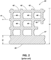
- FIG. 2 shows the embodiment of the BSS with a continuous counter current belt moving between two longitudinal, parallel planar electrodes (electrodes not shown).
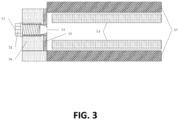
- Inside edge walls (55 of FIG. 3 ) of the separation chamber are not directly swept by the belt 45. It is desirable to minimize the area of the unswept zone (see FIG. 3 , located between belt 54 and abrasion resistant edge wall 55) of the edges of the separation chamber, since it represents electrode area that is not effective for particle separation. However, it is also typical to leave a gap between the edge 49 of the belt 45 and the inside edge of the separation chamber to prevent the belt from rubbing and wearing against the inside edge wall of the separation chamber (see 55 of FIG. 3 ), which could lead to early belt failure. Therefore the width W (see FIG.
- the belt 45 is approximately 20 mm narrower than the width of the separation chamber, in order to leave about 10 mm clearance between the inside edge wall (55 of FIG. 3 ) of the separation chamber and the edges 49 of the belt 45.
- This unswept area provides a location for difficult-to-fluidize feed to accumulate, which over time can be compacted by the motion of the separator belt, providing an abrasive surface for the belt to rub against, thereby reducing its operating life due to failure by edge abrasion and other related failure modes.
- Belts may be made of various materials. For example, woven belts or extruded belts may be used.
- UHMWPE ultra high molecular weight polyethylene
- UHMWPE sheet belts 45 have proven to have much longer life than extruded belts. In certain applications, such as the separation of unburned carbon from coal combustion fly ash, these UMHWPE belts have had been tested and shown to have a maximum life of up to 1950 hours before failure.
- the fluidization characteristics of powders is one parameter in determining how the particles of the powder are conveyed and separated in a BSS.
- Section 3.5 in Pneumatic Conveying of Solids by Klinzig G.E. et al., second edition 1997 describes materials loosely as "fluidizable” or "difficult-to-fluidize”. This property is qualitatively assessed by the behavior of the material in a fluidized bed.
- the fluidization property of powders is generally accepted to be influenced by the powder particle size, specific gravity, particle shape, surface moisture, and by other less well understood properties.
- Coal combustion fly ash is an example of an easily fluidizable powder. Many other industrial mineral powders are more difficult to fluidize than fly ash.
- Difficult-to-fluidize powders can greatly reduce the operating life of the BSS belt by providing a compacted surface for the belt edge 49 to rub against at high velocity, for example 40 miles per hour.
- the shear force generated by the moving belt 45 is not typically sufficient to overcome the interparticle forces in the powder, which results in a build-up of compacted, thermally insulating, abrasive powder on the inside edge of the separation chamber in the zone between the inside edge wall of the separation chamber (for example, see 55 on FIG. 3 and FIG. 4 ) and the edges 49 of the belt 45 that the belt 45 does not sweep. Over hours of operation this reduces the width of the belt edge strands 47, e, until the belts edge strand 47 is removed completely and the open cells of the belt 46 are exposed.
- thermoplastic-powder composite that was retrieved from a belt failure caused by the buildup of this composite residue has been measured as approximately 50% thermoplastic and 50% industrial mineral powder.
- Belt motor torque is the sum of the forces acting against the belt as it travels through the electrode gap. Belt motor torque increases with the amount of powder present in the separator, the distance between the opposing electrodes, the coarseness and degree of fluidization of the powder and the speed of the belt. Difficult-to-fluidize powders increase the belt motor torque required at a given processing condition by accumulating on the unswept edges of the separation chamber, providing a surface for the belt to wear. Elevated belt motor torques can result in increased belt wear and more frequent process shutdowns due to belt stoppage or belt breaks.
- Gas separator systems may be provided that include gas nozzles to disperse and fluidize difficult to fluidize materials or particles that may reside in unswept areas of the system or on the belt.
- the gas nozzles may be referred to as air nozzles, pressured gas nozzles, or pressurized air nozzles.
- the gas may be any inert gas that maintains the gas phase upon addition to a belt-type separator system.
- the gas may be air or pressurized air.
- the system may comprise one or more gas nozzles that may be installed to penetrate the longitudinal edge of the separation zone of a belt separator apparatus or system and inject, for example, compressed gas, that may aerate difficult-to-fluidize powders that would otherwise remain stagnant on the unswept edges of the separation zone.
- the system of one or more gas nozzles has been shown to have a beneficial effect on the longevity of the separator belt, reducing early belt failures due to belt edge abrasion.
- embodiments of the disclosure have been demonstrated to reduce the frequency of solid deposit formation due to belt material and powder compounding.
- Embodiments of the disclosure have also been shown to allow for a reduction in the operating belt motor torque of the belt separator apparatus, allowing for separation to occur at narrower electrode gaps and higher voltage gradients, leading to an improvement in separation performance.
- Such a system of compressed gas, for example air, injectors comprises one or more nozzles located in the system to provide gas, for example, pressurized gas, to the system to disperse particles within the system.
- the nozzles may be located in the longitudinal edge of the belt separator apparatus wall, directed in such a way as to supply compressed gas at angles to provide such dispersal of particles. The angles may range from perpendicular to the direction of travel of the separator belt to 45 degrees from normal relative to the direction of travel of the belt.
- Gas nozzles for example air nozzles, may be operated in such a way as to supply gas, such as air, continuously during operation, or intermittently by a timing device.
- gas may be delivered for an interval between about zero or 1 to about 30 seconds.
- gas may be delivered for an interval of about 10 seconds.
- gas may be delivered first at an interval of about 10 seconds, then at an interval of about 30 seconds, and then at another interval of about 20 seconds.
- the nozzles may comprise one or more air outlets in order to maximize the efficiency of the one or more nozzles in dispersing and/or fluidizing the material.
- the nozzles may be spaced at desired positions throughout out the system to provide an optimal dispersal and/or fluidization of material.
- the nozzles may be spaced at between about 1 inch to about 12 inch intervals. Each interval between positioned nozzle may be the same or different, depending on the desired pressurized air release to the system in order to achieve optimal or desired dispersal and/or fluidization of material.
- Nozzles may be operated at pressures ranging from about 69 kilopascals (10 psig) to about 689 kilopascals (100 psig), although a set point of about 172 kilopascals (25 psig) may be selected in some applications.
- FIG. 3 and FIG. 4 One embodiment of such a system of gas nozzles is shown in FIG. 3 and FIG. 4 .
- the gas nozzle 51 is installed through the wall of the belt separator system 56 and the abrasion resistant edge wall 55.
- Compressed gas at a pressure between about 69 kilopascals (10 psig) and about 689 kilopascals (100 psig) is supplied to the nozzle inlet 52.
- the compressed gas may be supplied at a controlled relative humidity, a controlled temperature, controlled relative humidity and temperature, or compressed air from ambient inlet conditions, without adjusting relative humidity or temperature.
- Ambient conditions may be conditions in which humidity is not controlled by a dehumidifier/humidifier, steam generator, liquid water addition, and/or temperature is not controlled by any type of heat exchange device.
- these properties of the gas are based upon the local weather conditions.
- a range of ambient conditions may be between about -23°C (-10°F) to about 38 °C (100 °F); between about 0% to about 100% relative humidity, at atmospheric pressure.
- the compressed gas is introduced into the separation chamber from the nozzle exit 53. Abrasive difficult to fluidize mineral deposits are thus removed from the path of travel of the separator open mesh belt 54 and separator electrodes 57 by the compressed gas stream.
- relative humidity is a humidity that changes with pressure. Therefore, the RH measured when the air is pressurized in the nozzle, and the RH measured immediately after the nozzle, at ambient pressure, will be different.
- process air is air that is conditioned for relative humidity and temperature to a selected relative humidity and temperature by one or more of a dehumidifier/humidifier, steam generator, liquid water addition, fan, blower, air compressor, or heat exchange device.
- the separation zone of the belt separator apparatus is a highly abrasive environment, as particles are moving at high velocity, for example, 40 miles per hour, relative to the separator electrodes. For this reason, it may be desirable to construct all components exposed to the particle stream of abrasion resistant materials to improve or maximize their service life. Included in this is the inside, longitudinal edge of the belt separator apparatus separation zone, which is constructed of an abrasion resistant, electrically insulating, ceramic material through which the air nozzles penetrate. Therefore, it is important to position or configure the gas nozzles in such a way as to maximize the fluidizing effect to the powder without exposing the nozzle to the abrasive high shear zone created by the belt.
- a key benefit of gas nozzles for difficult to fluidize powders is a significant improvement in the longevity of separator belts due to reduced edge wear. Gas nozzles have also been shown to be effective in reducing the frequency of solid belt and mineral deposits forming along the edge of the belt separator system when processing difficult to fluidize materials.
- the benefit of using gas nozzles has been measured directly as a reduction in the amount of torque required to drive the belt separator apparatus belt, referred to as "belt torque" or “belt motor torque.”
- the torque requirements to drive the belt may be determined by one or more factors including the distance between the opposing electrodes, the speed of the belt, the thickness and material of construction of the belt, the particle size distribution and fluidization properties of the powder being processed, and the rate of powder processed.
- the gas nozzles reduce the belt motor torque requirements by reducing losses to friction at the edge of the belt, where the belt is moving at high velocity against otherwise stagnant, difficult-to-fluidize powder. Additional reduction in belt motor torque occurs through fluidization of the feed, for example, a mineral feed, entering the belt separator system through the active feed port. It may be desirable to operate using lower belt motor torque as it allows for less belt wear and allows for more aggressive processing conditions. Furthermore, by requiring less torque to drive the separator belt, less static tension pressure is required to transfer motion from the drive rollers to the separator belt without slipping. This results in increased belt longevity due to longer times before belt failure due to belt material stretching.
- One consequence of failing to adequately control relative humidity in a triboelectrostatic BSS may be the accumulation of finely ground, electrically insulating, mineral powders on the surface of the electrodes, which are unable to be removed by the action of the separator belt. These accumulations of insulating layers on the surface of the electrodes may have the effect of reducing the electric field and thus reducing the efficiency of the electrostatic separation. It therefore may be desirable to optimize the relative humidity of the air supplied to the air nozzles to prevent these accumulations of electrically insulating powder.
- the separation process itself may be optimized, as removing the electrically insulating powder deposits at the locations of the air nozzles, through optimum relative humidity control, the electrodes may be brought closer together during processing, resulting in a higher electric field strength, better cleaning action of the continuous loop belt and increased particle to particle contact.
- a source of gas such as a source of air
- a source of gas may be provided to be delivered through one or more gas nozzles to provide gas to the system, for example, the separation chamber or the separation zone.
- the gas provided to the system may be the gas provided to the system after delivery through the nozzle, i.e., an expanded gas.
- the gas from the source of gas may be at selected conditions such that after the gas has expanded through the nozzle it is provided at at least one of a pre-determined temperature and a pre-determined pressure of the expanded gas.
- the gas provided to the system may have a pre-determined relative humidity and/or pre-determined temperature.
- the gas provided to the system having the pre-determined relative humidity and/or pre-determined temperature may be provided to the system, for example, the separation zone or chamber, through conditioning of the source of gas.
- the pre-determined relative humidity of the gas provided to the system may be between about 0% relative humidity to about 75% relative humidity.
- the pre-determined temperature of the gas provided to the system may be between about 16°C (60°F) and about 121°C (250°F).
- the air that may be conditioned may be conditions from a feed air source.
- the conditioning of the air to provide for pre-determined relative humidity and/or temperature may be achieved through a dehumidifier/humidifier, steam generator, liquid water addition, fan, blower, air compressor, or heat exchange device.
- FIG. 5A there is illustrated a plan view of an improved belt for a BSS, particularly for processing and separating some industrial materials (particularly non-fluidized materials).
- the improved belt design 50 has been provided with continuous (having a width Wi of about 20 to about 30 mm wide) edge strands 47 on each side of the belt (only one side of the belt is illustrated), which have been modified by creating open notches 52 of a prescribed shape and location. These notches 52 can be obtained through various forming means such as molding, punching, machining, water jet cutting, laser cutting, and the like.
- the edge notches 52 of FIG. 5A provide a mechanism, pathway and conveying mechanism for powder sandwiched between edge strands 47 of oppositely moving belt segments 28, 30 (see FIG. 1 ) to convey the particles of powder in either direction of belt motion. It is to be appreciated that the removal of stagnant powder between the edge strands 47 of oppositely moving belt segments 28, 30 (see FIG. 1 ) significantly reduces abrasion and frictional heating.
- This belt 50 having such edge notches 52 has been tested in existing BSS of FIG. 1 , and it has been shown that the use of belts with notched edges 52 has eliminated the formation of the plastic-powder composite build-up material that has historically resulted in short belt file. This belt 50 having such edge notches 52 has been tested in existing BSS of FIG.
- the trailing edge 54 of the notch 52 perpendicular to the edge of the belt 49 and the direction the belt is moving 41 provides a motive force to move powder in the direction of the belt motion.
- the volume of the notch 52 which is determined by depth of notch D, length of notch L, angle ⁇ , and thickness t of the belt (See FIG. 5B ), provides the carrying capacity of each notch 52.
- FIG. 5B illustrates a side view of the belt 50 and the notch 52, and in particular illustrates that the edges of the notch, such as the trailing edge 46, can be provided we a bevel having a bevel radius of b.
- the improved belt design described herein may be used in conjunction with the gas nozzles disclosed herein in order to improve the performance and life of the belt separator system.
- a system of air nozzles was installed on a test section of a belt separator apparatus and cycled on and off on a periodic basis.
- a total of 26 air nozzles were installed on a single side of a belt separator system, each nozzle was spaced 4 inches apart.
- Nozzle size varied between 0.020 to 0.040 inches in diameter.
- Several air nozzles had multiple (for example two or three) air injector locations. Other air nozzles had one air injector location.
- Air pressure at the pipe header prior to the nozzles was maintained at about 60 psig.
- Compressed air was introduced at low relative humidity, for example below 5% relative humidity when measured at ambient pressure (0 psig), and was not adjusted to match the relative humidity of the process air used to control the RH of the separator feed material.
- Nozzles were operated in a repeating cycle; nozzles were off for about 30 seconds, and then nozzles were on for about 10 seconds.
- Belt motor torque for the time period when the air nozzles was on averaged 30% of full motor load.
- Belt motor torque for time when the air nozzles were cycled off was 33%.
- a regular and periodic oscillation was observed during the time when the air nozzles were cycled on and off. For time periods when the air nozzles were on, the belt motor torque was, on average, 10% lower in relative terms.
- the belt motor torque increased.
- a system of air nozzles was installed on the entire length of a belt separator apparatus. Intervals of 4 inches were used between each air injection point. Air nozzle size was 0.040 inches in diameter. Air nozzles were operated continuously while the separator belt was operating. Compressed air was supplied at about 15 to about 25 psig. The operation of the air nozzles was found to have a significant effect on the operating life of the separator belt. Maximum belt life without any air nozzles was 124 hours. Maximum belt life with air nozzles supplying compressed, dried air at low relative humidity was 272 hours. Maximum belt life with air nozzles supplying compressed air, RH conditioned to match the relative humidity of the process air, was 628 hours.
- a system of air nozzles was installed and operated on the entire length of a belt separator apparatus. Intervals of 4 inches were used between each air injection point. Air nozzle size was 0.040 inches in diameter. Air nozzles were operated continuously while the separator belt was operating. Compressed air was supplied at about 15 - 25 psig. The relative humidity of the air supplied to the air nozzles was found to have a significant effect on the depth of electrode coating by finely ground, electrically insulating mineral powder. With dry, for example below 5% relative humidity when measured at ambient pressure (0 psig), compressed air supplied to the air nozzles, electrode coating was 1.2 - 2.1 kg/m 2 of electrode area for areas where electrode coating was evident, generally near the separator wall, adjacent to the air jets. Electrode coating by fine particles was less than 0.3 kg/m 2 of electrode area for areas in which electrode coating was observed when the air nozzles were operated with RH controlled air at a relative humidity equal to that of the process air.
- a synthetic (95%/5%) mixture of ground, agricultural grade calcium carbonate (Poultrycal 120) and silica sand (Flint) with a mean particle size of 60 microns was separated by a belt separator apparatus without air nozzles.
- a series of separation experiments was performed at constant operating conditions, except for the distance between the two opposing electrodes, the electrode gap, which was varied from 0.48 to 0.38 inches, in evenly spaced intervals of 0.02 inches.
- the rejection of acid insoluble (AI) silica sand was increased as the content of silica sand was decreased in the low AI, calcium carbonate enriched product.
- the belt motor torques increased as the electrode gap decreased.
- a synthetic (95%/5%) mixture of ground, agricultural grade calcium carbonate (Poultrycal 120) and silica sand (Flint) with a mean particle size of 60 microns was separated by a belt separator apparatus without air nozzles.
- a series of separation experiments was performed at constant operating conditions, except for the strength of the electric field between the two opposing electrodes, which was varied from about 20 kV/inch to about 50 kV/inch, in increments of 10 kV/inch. As electric field strength increased, the silica sand remaining in the carbonate enriched product decreased.
- a belt separator system comprising at least one gas nozzle, methods of operating the same and fluidizing a particle mixture, and methods of facilitating an operating life of a belt separation system. Accordingly, the foregoing description is by way of example and is not intended to be limiting. The application is limited only as defined in the following claims.
Landscapes
- Electrostatic Separation (AREA)
- Battery Electrode And Active Subsutance (AREA)
- Combined Means For Separation Of Solids (AREA)
- Structure Of Belt Conveyors (AREA)
- Separation Using Semi-Permeable Membranes (AREA)
Claims (17)
- Bandtrennsystem (56), umfassend:eine erste Elektrode und eine zweite Elektrode, die auf einander gegenüberliegenden Seiten einer längs verlaufenden Mittellinie angeordnet und zum Bereitstellen eines elektrischen Feldes zwischen der ersten und der zweiten Elektrode ausgelegt sind;eine erste Walze, die an einem ersten Ende des Systems angeordnet ist;eine zweite Walze, die an einem zweiten Ende des Systems angeordnet ist;ein Endlosband (54), das zwischen der ersten und der zweiten Elektrode angeordnet und durch die erste Walze und die zweite Walze getragen wird;eine Trennzone, die durch und zwischen dem Endlosband und Seitenwänden (55) der Trennzone definiert ist; undgekennzeichnet durch eine Vielzahl von Gasdüsen (51), die in regelmäßigen Abständen entlang einer oder mehrerer der Seitenwände positioniert sind, um Gas in die Trennzone abzugeben, und ein Mittel zur Steuerung der Bedingungen des in die Trennzone eintretenden Gases.
- Bandtrennsystem (56) nach Anspruch 1, ferner umfassend eine Gasquelle, die fluidisch mit einem Einlass mindestens einer Gasdüse (51) der Vielzahl von Gasdüsen (51) verbunden ist.
- Bandtrennsystem (56) nach Anspruch 2, wobei die Gasquelle ein Druckgas ist, wobei die Gasquelle optional Druckluft ist oder wobei die Druckgasquelle unter Umgebungsbedingungen steht.
- Bandtrennsystem (56) nach Anspruch 3, wobei die Gasquelle unter einer ausgewählten relativen Feuchtigkeitsbedingung steht, um eine vorbestimmte relative Feuchtigkeit in der Trennzone bereitzustellen, wobei die vorbestimmte relative Feuchtigkeit optional in einem Bereich von etwa 0 % bis etwa 75 % in der Trennzone liegt.
- Bandtrennsystem (56) nach Anspruch 3, wobei die Gasquelle unter einer ausgewählten Temperaturbedingung steht, um eine vorbestimmte Temperatur in der Trennzone bereitzustellen, wobei die vorbestimmte Temperatur optional in einem Bereich von etwa 16 °C (60 °F) bis etwa 121 °C (250 °F) in der Trennzone liegt.
- Bandtrennsystem (56) nach Anspruch 4, wobei:a) die Gasquelle unter einer ausgewählten Temperaturbedingung steht, um eine vorbestimmte Temperatur in der Trennzone bereitzustellen, wobei optional die vorbestimmte relative Feuchtigkeit in einem Bereich von etwa 0 % bis etwa 75 % und die vorbestimmte Temperatur in einem Bereich von etwa 16 °C (60 °F) bis etwa 121 °C (250 °F) in der Trennzone liegt; oderb) die vorbestimmte relative Feuchtigkeit durch mindestens eines von Entfeuchtung, Dampfzugabe und Flüssigwasserzugabe zur Gasquelle bereitgestellt wird; oderc) das Gas so aufbereitet ist, dass es eine relative Feuchtigkeit etwa gleich einer relativen Feuchtigkeit einer Prozessluft in der Trennzone aufweist; oderd) das Gas trockene Luft ist.
- Bandtrennsystem (56) nach Anspruch 1, wobei:a) die Vielzahl von Gasdüsen (51) dazu ausgelegt sind, Druckgas auf mindestens einer von einer kontinuierlichen und einer intermittierenden Basis abzugeben, wobei das System optional ferner eine Zeitsteuerungsvorrichtung umfasst, um Gas auf der intermittierenden Basis in einem vorbestimmten Intervall bereitzustellen, wobei optional das vorbestimmte Intervall zwischen etwa null Sekunden und etwa 30 Sekunden, optional etwa 10 Sekunden beträgt; oderb) das Bandtrennsystem ferner eine Gasquelle umfasst, die fluidisch mit einem Einlass mindestens einer Gasdüse (51) der Vielzahl von Gasdüsen (51) verbunden ist, wobei die Gasquelle ein Druckgas ist und die Vielzahl von Gasdüsen dazu ausgelegt ist, Druckgas mit einem Druck von etwa 69 Kilopascal (10 Pfund pro Quadratzoll Überdruck (psig)) bis etwa 689 Kilopascal (100 psig) abzugeben, wobei die Vielzahl von Gasdüsen optional dazu ausgelegt ist, Druckgas mit einem Druck von etwa 103 Kilopascal (15 psig) bis etwa 172 Kilopascal (25 psig), optional etwa 172 Kilopascal (25 psig) oder etwa 414 Kilopascal (60 psig) abzugeben; oderc) die Vielzahl von Luftdüsen so positioniert sind, dass sie ein zu trennendes Pulver im System maximal fluidisieren, ohne die Luftdüsen einer abrasiven Hochscherzone auszusetzen, die durch das Endlosband (54) erzeugt wird, wobei die Vielzahl von Gasdüsen (51) optional in einem Winkelbereich von etwa 90 Grad zur Bewegungsrichtung des Endlosbandes bis 45 Grad von der Normalen relativ zur Bewegungsrichtung des Bandes positioniert sind.
- Bandtrennsystem (56) nach Anspruch 1:a) ferner umfassend ein abriebfestes, elektrisch isolierendes, keramisches Material, das auf der einen oder den mehreren Seitenwänden innerhalb der Trennzone positioniert ist; oderb) wobei die Vielzahl von Luftdüsen über die einen oder die mehreren Seitenwände und eine abriebfeste Auskleidung installiert sind, die angrenzend an der einen oder den mehreren Seitenwänden positioniert ist.
- Bandtrennsystem (56) nach Anspruch 4, wobei die Gasquelle fluidisch mit mindestens einem von einem Entfeuchtungssystem, einer Dampfquelle und einer Flüssigwasserquelle verbunden ist.
- Bandtrennsystem (56) nach Anspruch 1, wobei das Endlosband (54) regelmäßige Kerben umfasst, die innerhalb einer Längskante an regelmäßigen Stellen in der Längskante des Bandes ausgebildet sind, wobei die regelmäßigen Kerben zum Fördern von Komponenten eines schwer zu fluidisierenden Materials in einer Richtung entlang einer Längsrichtung des Bandtrennsystems ausgelegt sind.
- Bandtrennsystem (56) nach Anspruch 10, wobei:a) die in der Längskante des Bandes ausgebildeten Kerben eine abgeschrägte Kante aufweisen, wobei die abgeschrägte Kante jeder Kerbe optional einen Radius im Bereich von 4-5 mm aufweist; oderb) die in der Längskante des Bandes ausgebildeten Kerben eine dreieckige Form aufweisen; oderc) eine Vorderkante der Kerbe einen Winkel im Bereich von etwa 12° bis etwa 45° in Bezug auf die Längskante aufweist; oderd) eine Hinterkante der Kerbe rechtwinklig zur Längskante steht; odere) das Band gegenläufige Bandsegmente enthält, die sich in entgegengesetzte Richtungen entlang der Längsrichtung bewegen; oderf) die Kerben in den Längskanten Abmessungen aufweisen, die ausgewählt sind, um den Durchsatz des Bandtrennsystems für ein schwer zu fluidisierendes Material zu maximieren; oderg) die Kerbe in der Längskante Abmessungen aufweist, die ausgewählt sind, um eine Betriebslebensdauer des Bandes für ein schwer zu fluidisierendes Material zu maximieren; oderh) das Band eine Breite aufweist, die etwa 1 bis 5 Millimeter kürzer als eine Breite der Innenseite des Bandtrennsystems ist, und die Kanten in den Längskanten des Bandes dazu ausgelegt sind, Komponenten des schwer zu fluidisierenden Materials von der Innenkante des Trennsystems wegzufegen.
- Verfahren zum Fluidisieren eines Partikelgemischs bei Verwendung eines Bandtrennsystems nach Anspruch 1, umfassend die Schritte:Einführen des Partikelgemischs in eine Zuführöffnung des Bandtrennsystems,Abgeben eines Gases durch mindestens eine Gasdüse (51) der Vielzahl von Gasdüsen (51), um Gas in die Trennzone abzugeben, und Steuern der Bedingungen des in die Trennzone eintretenden Gases.
- Verfahren nach Anspruch 12, wobei:a) das Abgeben des Gases durch mindestens eine Gasdüse (51) der Vielzahl von Gasdüsen (51) das Abgeben eines Druckgases umfasst; oderb) das Abgeben des Gases durch mindestens eine Gasdüse (51) der Vielzahl von Gasdüsen (51) das intermittierende Abgeben eines Gases für ein vorbestimmtes Intervall umfasst, optional ferner umfassend das intermittierende Abgeben des Gases durch die Gasdüse in einem vorbestimmten Intervall zwischen etwa null Sekunden und etwa 30 Sekunden, wobei das vorbestimmte Intervall optional etwa 10 Sekunden beträgt; oderc) das Abgeben eines Gases durch mindestens eine Gasdüse (51) der Vielzahl von Gasdüsen (51) das Abgeben des Gases durch eine Gasdüse mit einem Druck von etwa 69 Kilopascal (10 Pfund pro Quadratzoll Überdruck (psig)) bis etwa 689 Kilopascal (100 psig) umfasst, wobei die Vielzahl von Gasdüsen optional dazu ausgelegt ist, Druckgas mit einem Druck von etwa 103 Kilopascal (15 psig) bis etwa 172 Kilopascal (25 psig), optional etwa 172 Kilopascal (25 psig) oder etwa 414 Kilopascal (60 psig) abzugeben; oderd) das Zuführen eines Gases durch mindestens eine Gasdüse (51) der Vielzahl von Gasdüsen (51) eine Verringerung des Bandmotordrehmoments um mindestens 10 % bewirkt; odere) das Zuführen eines Gases durch mindestens eine Gasdüse (51) der Vielzahl von Gasdüsen (51) eine Erhöhung der Bandlebensdauer des Endlosbandes (54) um mindestens 100 % bewirkt.
- Verfahren nach Anspruch 12, ferner umfassend:a) Betreiben des Endlosbandes (54) mit einer Geschwindigkeit zwischen etwa 3 Metern pro Sekunde (10 Fuß pro Sekunde) und etwa 30 Metern pro Sekunde (100 Fuß pro Sekunde); oderb) Zuführen eines Gases, um das Gas mit einer vorbestimmten relativen Feuchtigkeit gleich der einer Prozessluft bereitzustellen, was eine Verringerung der Elektrodenbeschichtung durch das Partikelgemisch um mindestens etwa 75 % bewirkt; oderc) Aufbereiten des Gases, um eine relative Feuchtigkeit gleich etwa einer relativen Feuchtigkeit einer Prozessluft zu erreichen; oderd) Aufbereiten des Gases, um vor dem Zuführen des Gases eine relative Feuchtigkeit von trockener Luft in der Trennzone zu erreichen; odere) mindestens eines von Befeuchten oder Entfeuchten des Gases vor dem Abgeben des Gases; oderf) Betreiben mit einer höheren Spannung im Vergleich zu einem System ohne Luftdüsen, wodurch die Trennung von elektrisch isolierenden Pulvern verbessert wird; oderg) Betreiben mit einem kleineren Elektrodenabstand im Vergleich zu einem System ohne Luftdüsen, wodurch die Trennung des Partikelgemischs verbessert wird.
- Herstellungsverfahren zur Verlängerung der Betriebslebensdauer eines Bandtrennsystems nach Anspruch 1, umfassend die Schritte:- Anordnen einer ersten Elektrode und einer zweiten Elektrode auf gegenüberliegenden Seiten einer Längsmittellinie und Ausbilden der ersten und der zweiten Elektrode, um ein elektrisches Feld zwischen diesen bereitzustellen;- Anordnen einer ersten Walze an einem ersten Ende des Systems;- Anordnen einer zweiten Walze an einem zweiten Ende des Systems;- Anordnen eines Endlosbandes (54) zwischen der ersten und der zweiten Elektrode so, dass das Endlosband durch die erste Walze und die zweite Walze getragen wird;- Bereitstellen von Seitenwänden (55) so, dass eine Trennzone durch und zwischen dem Endlosband (54) und den Seitenwänden (55) definiert ist;Installieren einer Vielzahl von Gasdüsen (51), die entlang einer oder mehrerer der Seitenwände (55) positioniert sind.
- Verfahren nach Anspruch 15, ferner umfassend:a) Verbinden der Vielzahl von Gasdüsen (51) mit einer Gasquelle; oderb) Verbinden der Vielzahl von Gasdüsen (51) mit einer Druckgasquelle; oderc) Verbinden der Vielzahl von Gasdüsen (51) mit einer Druckgasquelle, die auf mindestens eine von einer vorbestimmten relativen Feuchtigkeit und einer vorbestimmten Temperatur aufbereitet ist, optional ferner umfassend:(i) Verbinden der Druckgasquelle mit mindestens einem von einem Entfeuchter, einer Dampfquelle und einer Flüssigwasserquelle.
- Verfahren nach Anspruch 15, wobei die Vielzahl von Gasdüsen (51) in einem Winkelbereich von etwa 90 Grad zur Bewegungsrichtung des Endlosbandes (54) bis 45 Grad von der Normalen relativ zur Bewegungsrichtung des Bandes positioniert sind.
Applications Claiming Priority (2)
| Application Number | Priority Date | Filing Date | Title |
|---|---|---|---|
| US14/622,450 US9764332B2 (en) | 2015-02-13 | 2015-02-13 | Edge air nozzles for belt-type separator devices |
| PCT/US2016/017394 WO2016130707A1 (en) | 2015-02-13 | 2016-02-10 | Edge air nozzles for belt-type separator devices |
Publications (2)
| Publication Number | Publication Date |
|---|---|
| EP3256259A1 EP3256259A1 (de) | 2017-12-20 |
| EP3256259B1 true EP3256259B1 (de) | 2024-10-23 |
Family
ID=55754398
Family Applications (1)
| Application Number | Title | Priority Date | Filing Date |
|---|---|---|---|
| EP16716716.2A Active EP3256259B1 (de) | 2015-02-13 | 2016-02-10 | Randluftdüsen für bandförmige trenneinrichtungen |
Country Status (14)
| Country | Link |
|---|---|
| US (1) | US9764332B2 (de) |
| EP (1) | EP3256259B1 (de) |
| JP (1) | JP6824174B2 (de) |
| KR (1) | KR102508633B1 (de) |
| AU (1) | AU2016219331B2 (de) |
| BR (1) | BR112017016203B1 (de) |
| CA (1) | CA2981498C (de) |
| CL (1) | CL2017002018A1 (de) |
| CO (1) | CO2017007937A2 (de) |
| ES (1) | ES3003108T3 (de) |
| FI (1) | FI3256259T3 (de) |
| RU (1) | RU2695575C2 (de) |
| WO (1) | WO2016130707A1 (de) |
| ZA (1) | ZA201705500B (de) |
Families Citing this family (2)
| Publication number | Priority date | Publication date | Assignee | Title |
|---|---|---|---|---|
| US9393573B2 (en) * | 2014-04-24 | 2016-07-19 | Separation Technologies Llc | Continuous belt for belt-type separator devices |
| CN115916387A (zh) | 2020-06-22 | 2023-04-04 | 分离技术有限责任公司 | 通过粒度和静电分离对细铁和极细铁矿石的干法选矿工艺 |
Citations (1)
| Publication number | Priority date | Publication date | Assignee | Title |
|---|---|---|---|---|
| WO1998031469A1 (en) * | 1997-01-15 | 1998-07-23 | Separation Technologies, Inc. | Belt separator system having improved belt geometry |
Family Cites Families (102)
| Publication number | Priority date | Publication date | Assignee | Title |
|---|---|---|---|---|
| US1110896A (en) | 1911-06-09 | 1914-09-15 | Harry Comstock | Electrostatic separator. |
| US1100896A (en) | 1913-12-08 | 1914-06-23 | Milton A Lokey | Fertilizer-mixer. |
| US1222305A (en) | 1914-10-27 | 1917-04-10 | Jakob Kraus | Electrostatic separator for inflammable materials. |
| US1355477A (en) | 1918-11-04 | 1920-10-12 | United Chemical & Organic Prod | Means for separating mixtures |
| US1931322A (en) | 1930-08-14 | 1933-10-17 | Goodrich Co B F | Spliced belt and method of splicing the same |
| DE705007C (de) | 1939-01-10 | 1941-04-15 | Metallgesellschaft Akt Ges | Elektrostatischer Scheider fuer Erze und sonstige Stoffe |
| FR940389A (fr) | 1947-02-07 | 1948-12-10 | Anciens Ets Skoda | Procédé et dispositif pour la séparation électrostatique de matière granuleuse |
| US2689648A (en) | 1952-02-18 | 1954-09-21 | Doenges Long Motors Inc | Separation of metallic from nonmetallic particles |
| US2758666A (en) | 1952-04-10 | 1956-08-14 | Phillips Petroleum Co | Carbon black separation |
| US2776725A (en) | 1954-05-20 | 1957-01-08 | Phillips Petroleum Co | Carbon black collecting and conveying systems |
| US2847124A (en) | 1955-02-08 | 1958-08-12 | Gen Mills Inc | Suppressor electrode for a perforated type of electrostatic separator machine |
| US2889042A (en) | 1955-09-22 | 1959-06-02 | Int Minerals & Chem Corp | Beneficiation of minerals |
| US3022889A (en) | 1959-01-19 | 1962-02-27 | Int Minerals & Chem Corp | Electrostatic separation of normally liquid materials |
| US3096277A (en) * | 1961-03-27 | 1963-07-02 | Thomas E Maestas | Electrostatic separator |
| US3247960A (en) | 1962-06-21 | 1966-04-26 | Gen Mills Inc | Electrostatic conditioning electrode separator |
| US3140714A (en) | 1962-06-28 | 1964-07-14 | Cordis Corp | Blood separation method |
| US3384692A (en) | 1962-12-06 | 1968-05-21 | Du Pont | Method for producing square-mesh net structure |
| GB1039898A (en) | 1964-06-10 | 1966-08-24 | Ira Stephens Ltd | Improvements in electrically heated presses for bonding ends of belts |
| US3449837A (en) | 1967-07-11 | 1969-06-17 | Gert Ottmuller | Drying peat |
| US3449938A (en) | 1967-08-03 | 1969-06-17 | Univ Utah | Method for separating and detecting fluid materials |
| US3493109A (en) | 1967-08-04 | 1970-02-03 | Consiglio Nazionale Ricerche | Process and apparatus for electrostatically separating ores with charging of the particles by triboelectricity |
| US3635340A (en) | 1969-01-31 | 1972-01-18 | F I N D Inc | Electrostatic separating apparatus for particles |
| US3664939A (en) | 1970-04-22 | 1972-05-23 | Univ California | ISOELECTRIC FOCUSING AND FRACTIONATION AMPHOLYTES IN THERMALLY ENGENDERED pH GRADIENTS |
| US3720312A (en) | 1970-07-09 | 1973-03-13 | Fmc Corp | Separation of particulate material by the application of electric fields |
| SU495088A1 (ru) | 1971-03-23 | 1975-12-15 | Государственный проектно-конструкторский и экспериментальный институт по обогатительному оборудованию | Трибоэлектрический сепаратор |
| SU498042A1 (ru) | 1972-02-25 | 1976-01-05 | Челябинский Институт Механизации И Электрофикации Сельского Хозяйства | Сепаратор дл разделени зерновых смесей в электростатическом поле с одновременным воздействием потоком воздуха |
| US3988410A (en) | 1973-10-09 | 1976-10-26 | Conwed Corporation | Lubricant for the production of nylon and polytetramethylene terephthalate net-like structures |
| US3941685A (en) | 1974-08-15 | 1976-03-02 | Kali Und Salz Aktiengesellschaft | Process for electrostatic separation of pyrite from crude coal |
| US4137156A (en) | 1975-03-21 | 1979-01-30 | Occidental Petroleum Corporation | Separation of non-magnetic conductive metals |
| US4211594A (en) | 1975-11-05 | 1980-07-08 | Sigri Elektrographit Gesellschaft Mit Beschrankter Haftung | Joining together shaped bodies of polytetrafluoroethylene |
| DE2609048C2 (de) | 1976-03-05 | 1983-12-15 | Kali Und Salz Ag, 3500 Kassel | Verfahren und Vorrichtung zur elektrostatischen Aufbereitung von Carnallit enthaltenden Kalirohsalzen |
| SU602225A1 (ru) | 1976-07-22 | 1978-04-15 | Челябинский Институт Механизации И Электрификации Сельского Хозяйства | Электростатический сепаратор дл сыпучих смесей |
| CA1081203A (en) | 1976-08-03 | 1980-07-08 | Kenneth A. Mackenzie | Process for preparing clay-based grease compositions |
| US4298518A (en) | 1976-09-06 | 1981-11-03 | Mitsubishi Chemical Industries, Ltd. | Polyamide resin composition |
| US4122002A (en) | 1977-05-09 | 1978-10-24 | Hauskins Jr John B | Method and apparatus for electrostatically separating particles from a mixture of particles |
| DE2737939A1 (de) | 1977-07-20 | 1979-02-01 | Staeubli Ag | Verbindung der beiden enden einer steuerkarte |
| FR2446422A1 (fr) | 1978-01-19 | 1980-08-08 | Renault | Courroie dentee de transmission de puissance |
| US4172028A (en) | 1978-09-29 | 1979-10-23 | Electro-Power-Tech., Inc. | Fine particle separation by electrostatically induced oscillation |
| US4321189A (en) | 1979-04-12 | 1982-03-23 | Toray Industries, Inc. | Flame retardant polyamide molding resin containing melamine cyanurate finely dispersed therein |
| US4274947A (en) | 1980-01-14 | 1981-06-23 | Beeckmans Jan M | Electrostatic method and apparatus for sorting fluidized particulate material |
| US4302245A (en) | 1980-06-20 | 1981-11-24 | American Can Company | Method for recovering zinc and zinc alloys from automobile scrap |
| SU975093A1 (ru) * | 1981-03-31 | 1982-11-23 | Курский Политехнический Институт | Устройство дл очистки и сортировки зерна |
| US4358358A (en) | 1981-10-06 | 1982-11-09 | The United States Of America As Represented By The Administrator Of The National Aeronautics And Space Administration | Static continuous electrophoresis device |
| CS225323B1 (en) | 1981-12-01 | 1984-02-13 | Zdenek Ing Csc Zapletal | The slab splicing of the viscosity of melt more than 103 poise |
| SU1007735A1 (ru) | 1982-01-08 | 1983-03-30 | Предприятие П/Я В-8413 | Способ непрерывного электростатического рассева мелкодисперсных порошкообразных материалов |
| US4440638A (en) | 1982-02-16 | 1984-04-03 | U.T. Board Of Regents | Surface field-effect device for manipulation of charged species |
| US4430146A (en) | 1982-02-22 | 1984-02-07 | Scandura, Inc. | Belt splicing apparatus and method and splice formed thereby |
| US4451357A (en) * | 1982-05-17 | 1984-05-29 | Lavigne Gordon | Apparatus for dry placer mining and method of operating same |
| US4517078A (en) | 1982-11-17 | 1985-05-14 | Blue Circle Industries Plc | Method and apparatus for separating particulate materials |
| US4482351A (en) | 1982-12-27 | 1984-11-13 | Hitachi Shipbuilding & Engineering Co., Ltd. | Process for removing ash from coal |
| US4476004A (en) | 1983-04-08 | 1984-10-09 | D.E.P. Systems, Inc. | Apparatus for electrofusion of biological particles |
| IT1212736B (it) | 1983-05-04 | 1989-11-30 | Pirelli | Cinghia di trasmissione. |
| US4650567A (en) * | 1983-05-18 | 1987-03-17 | The Standard Oil Company | Apparatus and method for flotation separation utilizing an improved spiral spray nozzle |
| US4701487A (en) | 1983-06-06 | 1987-10-20 | Petrolite Corporation | Extrusion processing aid composition and polyolefin containing same |
| US4533447A (en) | 1983-06-13 | 1985-08-06 | Meldon Jerry H | Apparatus for and method of isoelectric focussing |
| SU1196033A1 (ru) | 1984-03-01 | 1985-12-07 | Vnii Solyanoj Promy | Электрический классификатор |
| DE3439042A1 (de) | 1984-10-25 | 1986-04-30 | Kali Und Salz Ag, 3500 Kassel | Verfahren zur elektrostatischen aufbereitung von kieserit enthaltenden, gemahlenen kalirohsalzen |
| DE3527599A1 (de) | 1985-08-01 | 1987-02-12 | Mabeg Maschinenbau Gmbh Nachf | Verfahren zum verbinden der freien enden des flexiblen transportbandes eines baendertischs |
| US4839032A (en) * | 1986-06-06 | 1989-06-13 | Advanced Energy Dynamics Inc. | Separating constituents of a mixture of particles |
| US4874507A (en) * | 1986-06-06 | 1989-10-17 | Whitlock David R | Separating constituents of a mixture of particles |
| SU1475720A1 (ru) | 1987-08-26 | 1989-04-30 | Московский институт инженеров сельскохозяйственного производства им.В.П.Горячкина | Устройство дл электросепарации сем н |
| US5006226A (en) | 1987-11-02 | 1991-04-09 | Burt Jr Leo O | Fluidized, dry bed, ore concentrator |
| RU1787555C (ru) | 1990-08-01 | 1993-01-15 | Читинский политехнический институт | Электростатический сепаратор |
| BE1004603A3 (fr) | 1990-10-26 | 1992-12-22 | Solvay | Compositions moulables a base de polyolefines et objets faconnes a partir de ces compositions. |
| IT1245165B (it) | 1991-02-15 | 1994-09-13 | Ente Naz Energia Elettrica | Sistema per controllare e regolare alimentatori ad impulsi di tensione per precipitatori elettrostatici |
| DE4127572C1 (de) | 1991-08-21 | 1993-03-11 | Kali Und Salz Ag, 3500 Kassel, De | |
| US5135974A (en) | 1991-09-23 | 1992-08-04 | Fr Polymers, Inc. | Cyanurate based fire retardant concentrates |
| US5251762A (en) | 1992-04-03 | 1993-10-12 | Carpco, Inc. | Electrostatic separation of particles |
| US5375721A (en) * | 1992-04-23 | 1994-12-27 | Lavigne; Gordon | Apparatus for dry placer mining |
| US5484061A (en) | 1992-08-04 | 1996-01-16 | Advanced Electrostatic Technologies, Inc. | Electrostatic sieving apparatus |
| US5698358A (en) | 1992-11-27 | 1997-12-16 | Xerox Corporation | Process for fabricating a belt with a seam having a curvilinear S shaped profile |
| US5513755A (en) * | 1993-02-03 | 1996-05-07 | Jtm Industries, Inc. | Method and apparatus for reducing carbon content in fly ash |
| US5299692A (en) * | 1993-02-03 | 1994-04-05 | Jtm Industries, Inc. | Method and apparatus for reducing carbon content in particulate mixtures |
| US5427663A (en) | 1993-06-08 | 1995-06-27 | British Technology Group Usa Inc. | Microlithographic array for macromolecule and cell fractionation |
| US5356682A (en) | 1993-06-17 | 1994-10-18 | Eastman Kodak Company | Ultrasonically spliced web |
| US5342250A (en) | 1993-08-31 | 1994-08-30 | Sanders Ronald W | Process for the manufacture of an endless transfer belt |
| DE4343625C1 (de) | 1993-12-21 | 1995-06-22 | Kali & Salz Beteiligungs Ag | Verfahren zur Aufbereitung von langbeinit- und anhydrithaltigen Kieserit-Konzentraten |
| US5449390A (en) | 1994-03-08 | 1995-09-12 | Wilhelm Environmental Technologies, Inc. | Flue gas conditioning system using vaporized sulfuric acid |
| US5562796A (en) | 1994-05-24 | 1996-10-08 | Dorner Mfg. Corp. | Heat press for joining the spliced ends of a conveyor belt |
| US5819946A (en) * | 1995-03-03 | 1998-10-13 | Separation Technologies, Inc. | Separation system belt construction |
| US5829598A (en) * | 1995-04-28 | 1998-11-03 | Separation Technologies, Inc. | Method and apparatus for electrostatic separation |
| WO1997020633A1 (en) | 1995-12-06 | 1997-06-12 | Separation Technologies, Inc. | An adjustable gap in an electrostatic separator |
| WO1997030661A1 (en) | 1996-02-21 | 1997-08-28 | Smith & Nephew Inc. | Trial wedges with magnetic attachments |
| US6074458A (en) * | 1997-02-24 | 2000-06-13 | Separation Technologies, Inc. | Method and apparatus for separation of unburned carbon from flyash |
| JPH10263963A (ja) * | 1997-03-27 | 1998-10-06 | Ntn Corp | 精密送り装置 |
| US6066194A (en) | 1998-04-17 | 2000-05-23 | American Standard Inc. | Electronic room air cleaner with variable speed motor |
| US6320148B1 (en) * | 1999-08-05 | 2001-11-20 | Roe-Hoan Yoon | Electrostatic method of separating particulate materials |
| US6375875B1 (en) | 2000-01-27 | 2002-04-23 | Ut-Battelle, Llc | Diagnostic monitor for carbon fiber processing |
| JP4830196B2 (ja) | 2000-12-12 | 2011-12-07 | パナソニック株式会社 | プラスチック粉砕物の静電選別装置 |
| JP2003126832A (ja) | 2001-08-10 | 2003-05-07 | Mitsubishi Heavy Ind Ltd | 石炭灰の処理装置及び計測装置 |
| ATE421052T1 (de) | 2001-09-27 | 2009-01-15 | Separation Technologies Llc | Verfahren zur herstellung eines endlosriemens für eine riementrennvorrichtung |
| JP2003154291A (ja) * | 2001-11-26 | 2003-05-27 | Nippon Kokan Pipe Fittings Mfg Co Ltd | 慣性分級装置 |
| DE10351180B3 (de) | 2003-11-03 | 2005-01-27 | K+S Kali Gmbh | Band eines elektrischen Bandabscheiders |
| RU49842U1 (ru) | 2005-04-25 | 2005-12-10 | Закрытое акционерное общество научно-производственная компания "Комбест" | Пневматическое устройство ударного действия |
| WO2007014402A1 (en) | 2005-07-25 | 2007-02-01 | Francoi Eberhardt Du Plessis | Method of and control system for controlling electrostatic separator |
| RU49588U1 (ru) | 2005-07-29 | 2005-11-27 | Иванов Александр Александрович | Погружной высокооборотный насосный агрегат |
| JP2007046805A (ja) | 2005-08-08 | 2007-02-22 | Chugoku Electric Power Co Inc:The | 石炭火力発電所におけるズリ除去装置および石炭供給設備 |
| JP4889268B2 (ja) | 2005-09-22 | 2012-03-07 | ルネサスエレクトロニクス株式会社 | Eepromとeepromの駆動方法 |
| JP4889269B2 (ja) | 2005-09-26 | 2012-03-07 | 和雄 村上 | 微生物固定化担体を用いた水質浄化装置 |
| CA2741224A1 (en) | 2010-05-26 | 2011-11-26 | Separation Technologies Llc | Recovery of mercury control reagents by tribo-electric separation |
| DE102010026445A1 (de) * | 2010-07-08 | 2012-01-12 | Evonik Degussa Gmbh | Flugaschetrennung mittels Koronaentladung |
| US8552326B2 (en) * | 2010-09-03 | 2013-10-08 | Separation Technologies Llc | Electrostatic separation control system |
-
2015
- 2015-02-13 US US14/622,450 patent/US9764332B2/en active Active
-
2016
- 2016-02-10 RU RU2017131845A patent/RU2695575C2/ru active
- 2016-02-10 CA CA2981498A patent/CA2981498C/en active Active
- 2016-02-10 JP JP2017542092A patent/JP6824174B2/ja active Active
- 2016-02-10 KR KR1020177022553A patent/KR102508633B1/ko active Active
- 2016-02-10 ES ES16716716T patent/ES3003108T3/es active Active
- 2016-02-10 BR BR112017016203-2A patent/BR112017016203B1/pt active IP Right Grant
- 2016-02-10 FI FIEP16716716.2T patent/FI3256259T3/fi active
- 2016-02-10 WO PCT/US2016/017394 patent/WO2016130707A1/en not_active Ceased
- 2016-02-10 AU AU2016219331A patent/AU2016219331B2/en active Active
- 2016-02-10 EP EP16716716.2A patent/EP3256259B1/de active Active
-
2017
- 2017-08-04 CO CONC2017/0007937A patent/CO2017007937A2/es unknown
- 2017-08-07 CL CL2017002018A patent/CL2017002018A1/es unknown
- 2017-08-14 ZA ZA2017/05500A patent/ZA201705500B/en unknown
Patent Citations (1)
| Publication number | Priority date | Publication date | Assignee | Title |
|---|---|---|---|---|
| WO1998031469A1 (en) * | 1997-01-15 | 1998-07-23 | Separation Technologies, Inc. | Belt separator system having improved belt geometry |
Also Published As
| Publication number | Publication date |
|---|---|
| BR112017016203A2 (pt) | 2018-03-27 |
| CA2981498C (en) | 2024-02-06 |
| US9764332B2 (en) | 2017-09-19 |
| ZA201705500B (en) | 2018-11-28 |
| FI3256259T3 (fi) | 2025-01-23 |
| JP6824174B2 (ja) | 2021-02-03 |
| US20160236206A1 (en) | 2016-08-18 |
| WO2016130707A1 (en) | 2016-08-18 |
| CA2981498A1 (en) | 2016-08-18 |
| RU2017131845A3 (de) | 2019-03-13 |
| AU2016219331A1 (en) | 2017-08-10 |
| KR102508633B1 (ko) | 2023-03-10 |
| CL2017002018A1 (es) | 2018-04-13 |
| RU2017131845A (ru) | 2019-03-13 |
| ES3003108T3 (en) | 2025-03-10 |
| BR112017016203B1 (pt) | 2022-06-21 |
| AU2016219331B2 (en) | 2021-03-04 |
| KR20170117076A (ko) | 2017-10-20 |
| RU2695575C2 (ru) | 2019-07-24 |
| JP2018506425A (ja) | 2018-03-08 |
| EP3256259A1 (de) | 2017-12-20 |
| CO2017007937A2 (es) | 2017-10-31 |
Similar Documents
| Publication | Publication Date | Title |
|---|---|---|
| KR101582849B1 (ko) | 양방향 기류를 가진 초미립 파우더 체거름 장치 | |
| Kosmider et al. | Polymeric nanofibres exhibit an enhanced air filtration performance | |
| US10092908B2 (en) | Continuous belt for belt-type separator devices | |
| CA2981498C (en) | Edge air nozzles for belt-type separator devices | |
| JP5147023B2 (ja) | 微粉状鉱物製品の製造方法 | |
| CN102942015A (zh) | 全密闭双气垫带式输送机 | |
| US9138780B2 (en) | Device and method for separating feedstock into at least one light material fraction and a heavy material fraction | |
| US20110217405A1 (en) | Method and installation for producing a non-woven web with dust removal | |
| EP3134213B1 (de) | Verbesserter endlosriemen für bandförmige trenneinrichtung | |
| JP2006015298A (ja) | 粉粒体の静電分離装置 | |
| CN101128713B (zh) | 流化床干燥机及利用流化床干燥机进行的湿润原料的干燥方法 | |
| CN105658444A (zh) | 粒状材料排放装置 | |
| JP7567613B2 (ja) | ドライアイスブラスト装置 | |
| JP7797411B2 (ja) | 粒子状材料を粉砕する装置及び方法 | |
| CN111285055A (zh) | 一种气垫带式输送机 | |
| CN120846058A (zh) | 一种结块物料破碎烘干装置 | |
| RU2320729C1 (ru) | Установка для распыления раствора обогащающей добавки на кристаллы сахара | |
| UA20570U (en) | Disintegrator of clay-containing raw material | |
| PL117170B3 (en) | Method and apparatus forming fibrous matsvki voloknistogo mata |
Legal Events
| Date | Code | Title | Description |
|---|---|---|---|
| STAA | Information on the status of an ep patent application or granted ep patent |
Free format text: STATUS: THE INTERNATIONAL PUBLICATION HAS BEEN MADE |
|
| PUAI | Public reference made under article 153(3) epc to a published international application that has entered the european phase |
Free format text: ORIGINAL CODE: 0009012 |
|
| STAA | Information on the status of an ep patent application or granted ep patent |
Free format text: STATUS: REQUEST FOR EXAMINATION WAS MADE |
|
| 17P | Request for examination filed |
Effective date: 20170823 |
|
| AK | Designated contracting states |
Kind code of ref document: A1 Designated state(s): AL AT BE BG CH CY CZ DE DK EE ES FI FR GB GR HR HU IE IS IT LI LT LU LV MC MK MT NL NO PL PT RO RS SE SI SK SM TR |
|
| AX | Request for extension of the european patent |
Extension state: BA ME |
|
| DAV | Request for validation of the european patent (deleted) | ||
| DAX | Request for extension of the european patent (deleted) | ||
| STAA | Information on the status of an ep patent application or granted ep patent |
Free format text: STATUS: EXAMINATION IS IN PROGRESS |
|
| 17Q | First examination report despatched |
Effective date: 20201209 |
|
| REG | Reference to a national code |
Ref country code: DE Ref legal event code: R079 Free format text: PREVIOUS MAIN CLASS: B03C0007080000 Ipc: B03C0007000000 Ref document number: 602016089928 Country of ref document: DE |
|
| RIC1 | Information provided on ipc code assigned before grant |
Ipc: B03C 7/08 20060101ALI20240327BHEP Ipc: B03C 7/00 20060101AFI20240327BHEP |
|
| GRAP | Despatch of communication of intention to grant a patent |
Free format text: ORIGINAL CODE: EPIDOSNIGR1 |
|
| STAA | Information on the status of an ep patent application or granted ep patent |
Free format text: STATUS: GRANT OF PATENT IS INTENDED |
|
| INTG | Intention to grant announced |
Effective date: 20240516 |
|
| GRAS | Grant fee paid |
Free format text: ORIGINAL CODE: EPIDOSNIGR3 |
|
| GRAA | (expected) grant |
Free format text: ORIGINAL CODE: 0009210 |
|
| STAA | Information on the status of an ep patent application or granted ep patent |
Free format text: STATUS: THE PATENT HAS BEEN GRANTED |
|
| AK | Designated contracting states |
Kind code of ref document: B1 Designated state(s): AL AT BE BG CH CY CZ DE DK EE ES FI FR GB GR HR HU IE IS IT LI LT LU LV MC MK MT NL NO PL PT RO RS SE SI SK SM TR |
|
| REG | Reference to a national code |
Ref country code: GB Ref legal event code: FG4D |
|
| REG | Reference to a national code |
Ref country code: CH Ref legal event code: EP |
|
| P01 | Opt-out of the competence of the unified patent court (upc) registered |
Free format text: CASE NUMBER: APP_54869/2024 Effective date: 20241004 |
|
| REG | Reference to a national code |
Ref country code: NL Ref legal event code: FP |
|
| REG | Reference to a national code |
Ref country code: DE Ref legal event code: R096 Ref document number: 602016089928 Country of ref document: DE |
|
| REG | Reference to a national code |
Ref country code: SE Ref legal event code: TRGR |
|
| REG | Reference to a national code |
Ref country code: IE Ref legal event code: FG4D |
|
| REG | Reference to a national code |
Ref country code: FI Ref legal event code: FGE |
|
| REG | Reference to a national code |
Ref country code: LT Ref legal event code: MG9D |
|
| REG | Reference to a national code |
Ref country code: ES Ref legal event code: FG2A Ref document number: 3003108 Country of ref document: ES Kind code of ref document: T3 Effective date: 20250310 |
|
| PG25 | Lapsed in a contracting state [announced via postgrant information from national office to epo] |
Ref country code: IS Free format text: LAPSE BECAUSE OF FAILURE TO SUBMIT A TRANSLATION OF THE DESCRIPTION OR TO PAY THE FEE WITHIN THE PRESCRIBED TIME-LIMIT Effective date: 20250223 Ref country code: PT Free format text: LAPSE BECAUSE OF FAILURE TO SUBMIT A TRANSLATION OF THE DESCRIPTION OR TO PAY THE FEE WITHIN THE PRESCRIBED TIME-LIMIT Effective date: 20250224 Ref country code: HR Free format text: LAPSE BECAUSE OF FAILURE TO SUBMIT A TRANSLATION OF THE DESCRIPTION OR TO PAY THE FEE WITHIN THE PRESCRIBED TIME-LIMIT Effective date: 20241023 |
|
| PG25 | Lapsed in a contracting state [announced via postgrant information from national office to epo] |
Ref country code: BG Free format text: LAPSE BECAUSE OF FAILURE TO SUBMIT A TRANSLATION OF THE DESCRIPTION OR TO PAY THE FEE WITHIN THE PRESCRIBED TIME-LIMIT Effective date: 20241023 |
|
| PG25 | Lapsed in a contracting state [announced via postgrant information from national office to epo] |
Ref country code: GR Free format text: LAPSE BECAUSE OF FAILURE TO SUBMIT A TRANSLATION OF THE DESCRIPTION OR TO PAY THE FEE WITHIN THE PRESCRIBED TIME-LIMIT Effective date: 20250124 Ref country code: LV Free format text: LAPSE BECAUSE OF FAILURE TO SUBMIT A TRANSLATION OF THE DESCRIPTION OR TO PAY THE FEE WITHIN THE PRESCRIBED TIME-LIMIT Effective date: 20241023 |
|
| PG25 | Lapsed in a contracting state [announced via postgrant information from national office to epo] |
Ref country code: PL Free format text: LAPSE BECAUSE OF FAILURE TO SUBMIT A TRANSLATION OF THE DESCRIPTION OR TO PAY THE FEE WITHIN THE PRESCRIBED TIME-LIMIT Effective date: 20241023 |
|
| PG25 | Lapsed in a contracting state [announced via postgrant information from national office to epo] |
Ref country code: RS Free format text: LAPSE BECAUSE OF FAILURE TO SUBMIT A TRANSLATION OF THE DESCRIPTION OR TO PAY THE FEE WITHIN THE PRESCRIBED TIME-LIMIT Effective date: 20250123 |
|
| PG25 | Lapsed in a contracting state [announced via postgrant information from national office to epo] |
Ref country code: SM Free format text: LAPSE BECAUSE OF FAILURE TO SUBMIT A TRANSLATION OF THE DESCRIPTION OR TO PAY THE FEE WITHIN THE PRESCRIBED TIME-LIMIT Effective date: 20241023 |
|
| PG25 | Lapsed in a contracting state [announced via postgrant information from national office to epo] |
Ref country code: DK Free format text: LAPSE BECAUSE OF FAILURE TO SUBMIT A TRANSLATION OF THE DESCRIPTION OR TO PAY THE FEE WITHIN THE PRESCRIBED TIME-LIMIT Effective date: 20241023 |
|
| PG25 | Lapsed in a contracting state [announced via postgrant information from national office to epo] |
Ref country code: EE Free format text: LAPSE BECAUSE OF FAILURE TO SUBMIT A TRANSLATION OF THE DESCRIPTION OR TO PAY THE FEE WITHIN THE PRESCRIBED TIME-LIMIT Effective date: 20241023 |
|
| PG25 | Lapsed in a contracting state [announced via postgrant information from national office to epo] |
Ref country code: RO Free format text: LAPSE BECAUSE OF FAILURE TO SUBMIT A TRANSLATION OF THE DESCRIPTION OR TO PAY THE FEE WITHIN THE PRESCRIBED TIME-LIMIT Effective date: 20241023 |
|
| REG | Reference to a national code |
Ref country code: DE Ref legal event code: R097 Ref document number: 602016089928 Country of ref document: DE |
|
| PG25 | Lapsed in a contracting state [announced via postgrant information from national office to epo] |
Ref country code: SK Free format text: LAPSE BECAUSE OF FAILURE TO SUBMIT A TRANSLATION OF THE DESCRIPTION OR TO PAY THE FEE WITHIN THE PRESCRIBED TIME-LIMIT Effective date: 20241023 |
|
| PG25 | Lapsed in a contracting state [announced via postgrant information from national office to epo] |
Ref country code: CZ Free format text: LAPSE BECAUSE OF FAILURE TO SUBMIT A TRANSLATION OF THE DESCRIPTION OR TO PAY THE FEE WITHIN THE PRESCRIBED TIME-LIMIT Effective date: 20241023 |
|
| PLBE | No opposition filed within time limit |
Free format text: ORIGINAL CODE: 0009261 |
|
| STAA | Information on the status of an ep patent application or granted ep patent |
Free format text: STATUS: NO OPPOSITION FILED WITHIN TIME LIMIT |
|
| PG25 | Lapsed in a contracting state [announced via postgrant information from national office to epo] |
Ref country code: MC Free format text: LAPSE BECAUSE OF FAILURE TO SUBMIT A TRANSLATION OF THE DESCRIPTION OR TO PAY THE FEE WITHIN THE PRESCRIBED TIME-LIMIT Effective date: 20241023 |
|
| REG | Reference to a national code |
Ref country code: CH Ref legal event code: PL |
|
| 26N | No opposition filed |
Effective date: 20250724 |
|
| PG25 | Lapsed in a contracting state [announced via postgrant information from national office to epo] |
Ref country code: LU Free format text: LAPSE BECAUSE OF NON-PAYMENT OF DUE FEES Effective date: 20250210 |
|
| PG25 | Lapsed in a contracting state [announced via postgrant information from national office to epo] |
Ref country code: CH Free format text: LAPSE BECAUSE OF NON-PAYMENT OF DUE FEES Effective date: 20250228 |
|
| GBPC | Gb: european patent ceased through non-payment of renewal fee |
Effective date: 20250210 |
|
| PG25 | Lapsed in a contracting state [announced via postgrant information from national office to epo] |
Ref country code: GB Free format text: LAPSE BECAUSE OF NON-PAYMENT OF DUE FEES Effective date: 20250210 |
|
| PG25 | Lapsed in a contracting state [announced via postgrant information from national office to epo] |
Ref country code: IE Free format text: LAPSE BECAUSE OF NON-PAYMENT OF DUE FEES Effective date: 20250210 |
|
| PGFP | Annual fee paid to national office [announced via postgrant information from national office to epo] |
Ref country code: NL Payment date: 20260226 Year of fee payment: 11 |
|
| PGFP | Annual fee paid to national office [announced via postgrant information from national office to epo] |
Ref country code: SE Payment date: 20260227 Year of fee payment: 11 |
|
| PGFP | Annual fee paid to national office [announced via postgrant information from national office to epo] |
Ref country code: ES Payment date: 20260302 Year of fee payment: 11 |
|
| PGFP | Annual fee paid to national office [announced via postgrant information from national office to epo] |
Ref country code: NO Payment date: 20260227 Year of fee payment: 11 Ref country code: DE Payment date: 20260227 Year of fee payment: 11 |
|
| PGFP | Annual fee paid to national office [announced via postgrant information from national office to epo] |
Ref country code: AT Payment date: 20260227 Year of fee payment: 11 |
|
| PGFP | Annual fee paid to national office [announced via postgrant information from national office to epo] |
Ref country code: BE Payment date: 20260227 Year of fee payment: 11 Ref country code: FI Payment date: 20260225 Year of fee payment: 11 Ref country code: IT Payment date: 20260219 Year of fee payment: 11 |
|
| PGFP | Annual fee paid to national office [announced via postgrant information from national office to epo] |
Ref country code: FR Payment date: 20260225 Year of fee payment: 11 |
|
| PGFP | Annual fee paid to national office [announced via postgrant information from national office to epo] |
Ref country code: TR Payment date: 20260127 Year of fee payment: 11 |