EP3255341A1 - Gasbrenner und haushaltsgargerät - Google Patents
Gasbrenner und haushaltsgargerät Download PDFInfo
- Publication number
- EP3255341A1 EP3255341A1 EP17173971.7A EP17173971A EP3255341A1 EP 3255341 A1 EP3255341 A1 EP 3255341A1 EP 17173971 A EP17173971 A EP 17173971A EP 3255341 A1 EP3255341 A1 EP 3255341A1
- Authority
- EP
- European Patent Office
- Prior art keywords
- burner
- gas
- adjusting device
- gas outlet
- gas burner
- Prior art date
- Legal status (The legal status is an assumption and is not a legal conclusion. Google has not performed a legal analysis and makes no representation as to the accuracy of the status listed.)
- Granted
Links
Images




Classifications
-
- F—MECHANICAL ENGINEERING; LIGHTING; HEATING; WEAPONS; BLASTING
- F23—COMBUSTION APPARATUS; COMBUSTION PROCESSES
- F23D—BURNERS
- F23D14/00—Burners for combustion of a gas, e.g. of a gas stored under pressure as a liquid
- F23D14/02—Premix gas burners, i.e. in which gaseous fuel is mixed with combustion air upstream of the combustion zone
- F23D14/04—Premix gas burners, i.e. in which gaseous fuel is mixed with combustion air upstream of the combustion zone induction type, e.g. Bunsen burner
- F23D14/06—Premix gas burners, i.e. in which gaseous fuel is mixed with combustion air upstream of the combustion zone induction type, e.g. Bunsen burner with radial outlets at the burner head
-
- F—MECHANICAL ENGINEERING; LIGHTING; HEATING; WEAPONS; BLASTING
- F23—COMBUSTION APPARATUS; COMBUSTION PROCESSES
- F23D—BURNERS
- F23D14/00—Burners for combustion of a gas, e.g. of a gas stored under pressure as a liquid
- F23D14/46—Details
- F23D14/48—Nozzles
- F23D14/58—Nozzles characterised by the shape or arrangement of the outlet or outlets from the nozzle, e.g. of annular configuration
- F23D14/583—Nozzles characterised by the shape or arrangement of the outlet or outlets from the nozzle, e.g. of annular configuration of elongated shape, e.g. slits
-
- F—MECHANICAL ENGINEERING; LIGHTING; HEATING; WEAPONS; BLASTING
- F23—COMBUSTION APPARATUS; COMBUSTION PROCESSES
- F23N—REGULATING OR CONTROLLING COMBUSTION
- F23N1/00—Regulating fuel supply
Definitions
- the present invention relates to a gas burner for a Marshsgar réelle and a Mullsgar réelle with such a gas burner.
- Gas burners for household cooking appliances comprise a burner base, which can be attached to a hob plate of the household cooking appliance, and a torch lid which can be placed on the burner base. Between the burner base and the burner cover, a plurality of gas outlet openings may be provided, which are arranged distributed uniformly over a circumference of the burner base. With the help of the gas outlet openings a primary air / fuel gas mixture is evenly distributed for flame formation. The gas outlet openings have a firmly defined opening cross-section.
- an object of the present invention is to provide an improved gas burner.
- the gas burner comprises a burner housing, which comprises at least one gas outlet opening, which can be flowed through by a primary air / fuel gas mixture for flame generation, and an adjusting device, which is set up to vary an opening cross section of the at least one gas outlet opening.
- the at least one gas outlet opening can also be referred to as a gas outlet channel.
- the at least one gas outlet opening fluidly connects a mixing chamber of the gas burner provided between a burner lower part and a burner cover of the burner housing with an environment of the gas burner. That is, the primary air / fuel gas mixture flows from the mixing chamber through the at least one gas outlet opening to the environment.
- a plurality of such gas outlet openings is provided.
- the primary air / fuel gas mixture is evenly distributed for flame formation.
- the term "vary” the term “change” can also be used.
- air in particular primary air and secondary air, is required.
- a gas nozzle injects the fuel gas in a downwardly open nozzle chamber of the gas burner. By injecting the fuel gas creates a Venturi effect and the primary air is sucked laterally past the gas nozzle in the nozzle chamber and mixed there with the fuel gas.
- the secondary air is in contrast, the air that is required to burn the emerging from the gas outlet opening primary air / fuel gas mixture.
- the opening cross section of the at least one gas outlet opening can be varied, an enlarged operating range of the gas burner can be achieved.
- a better adjustability of the burner flame is possible to ensure flame stability under different operating conditions. It is achieved a better gas combustion, whereby the pollutant emissions of the gas burner is minimized.
- the efficiency of the gas burner is significantly improved. In particular, good combustion is also ensured in a so-called booster operation of the gas burner, in which the gas burner is supplied with a maximum possible amount of fuel gas.
- the gas burner comprises a plurality of gas outlet openings, wherein the adjusting device is adapted to simultaneously vary the opening cross sections of all gas outlet openings.
- the number of gas outlet openings is arbitrary.
- the gas outlet openings are arranged distributed uniformly around a circumference of the burner base.
- the adjusting device is configured to selectively reduce or enlarge the opening cross section of the at least one gas outlet opening.
- the gas burner can be easily and conveniently adapted to a wide variety of operating conditions and to different fuel gases.
- the adjusting device is adapted to vary a volume of a mixing chamber of the gas burner, in particular either to reduce or enlarge.
- the volume of the primary air / fuel gas mixture in the mixing chamber can be adjusted depending on the operating condition of the gas burner. This improves the combustion and the efficiency of the gas burner is further improved.
- the variation of the volume of the mixing chamber takes place simultaneously and in the same direction with the variation of the opening cross section. That is, at one Reduction of the opening cross-section also reduces the volume of the mixing chamber and vice versa.
- the burner housing has a burner lower part and a burner cover placed on the lower burner part, wherein the at least one gas outlet opening is provided on the burner lower part.
- the at least one gas outlet opening can also be provided on the burner cover.
- the metallic burner base and the burner cover are made of a steel, aluminum or magnesium material.
- the burner base and the burner cap are die-cast aluminum components. As a result, the gas burner can be inexpensively manufactured in large quantities.
- the adjusting device for varying the opening cross section of the at least one gas outlet opening along a central axis of the burner housing is linearly displaceable.
- a drive element For displacing the adjusting device, a drive element can be provided, which is assigned to the gas burner.
- the drive element may be, for example, an electric motor or an electromagnet.
- the adjusting device is preferably arranged in the mixing chamber.
- the drive element may be operatively connected to a gas control valve of the gas burner such that the drive element actuates the adjustment device as a function of a position of the gas control valve in order to vary the opening cross section and / or the volume of the mixing chamber.
- the adjusting device has an adjusting body, which is arranged in the at least one gas outlet opening and which is linearly displaceable along the central axis for varying the opening cross section of the at least one gas outlet opening.
- the adjusting body is pin-shaped.
- the adjusting body is linearly displaceable within the at least one gas outlet opening along the central axis.
- the adjusting device has a plurality of adjusting body, a fastening element and a support ring, wherein the Adjusting arranged evenly distributed around a circumference of the support ring and secured by means of the fastener to the support ring.
- the support ring is disk-shaped.
- the fastening element may be a spring element.
- the adjustment can also be formed centrein Anlagenig. That is, the adjusting body and the support ring are integrally formed. As a result, can be dispensed with the fastener.
- the adjusting device has at least one guide element which is guided linearly on a burner lower part of the burner housing.
- the guide element is pin-shaped and the guide element is linearly guided in a recess provided on the burner lower part.
- the burner lower part comprises a guide disc accommodated therein, in which the recess is provided.
- the adjusting device has a plurality of guide elements, for example three, and the burner lower part has a corresponding number of recesses.
- the adjusting device for varying the opening cross section of the at least one gas outlet opening is rotatable about a central axis of the burner housing.
- the adjusting device has an annular base portion, on the edge side a plurality of evenly distributed over a circumference of the base portion adjusting elements is provided.
- the adjusting elements are preferably provided tooth-shaped on an outer edge of the base portion.
- the base portion and the adjusting elements are made of one piece material.
- the adjusting elements cover or release the gas outlet openings.
- the opening cross section of the at least one gas outlet opening is round or rectangular.
- the opening cross section may also have any other geometries.
- a Swsgarêt in particular a gas stove, proposed with such a gas burner and a gas control valve for adjusting a fuel gas volume flow to the gas burner.
- the household cooking appliance can be a stand-alone appliance or a built-in appliance.
- the household cooking appliance is a household gas stove.
- the household cooking appliance may have a plurality of such gas burners.
- the household cooker may have four gas burners.
- Each gas burner is assigned its own gas control valve.
- the gas control valve is clamped to a main gas line of Marshsgar réelles and connected via a gas supply line with its associated gas burner.
- each gas burner can also be assigned an ignition device which can be integrated in the gas control valve and an ignition element arranged directly on the gas burner, for example a spark plug.
- the household cooking appliance comprises a drive element for driving the setting device, wherein the drive element is coupled to the gas control valve such that the setting device is adapted to vary the at least one opening cross section as a function of the fuel gas volume flow.
- the drive element can be assigned to the setting device.
- the drive element can be arranged directly on the gas burner or integrated into it.
- the drive element may be, for example, an electric motor, an electromagnet, a piezoelectric element or the like.
- the Millersgarêt may also have a control device which is adapted to control the drive element.
- the control device can with the drive element and the Gas control valve operatively connected. With the aid of the drive element can also, as already mentioned, the volume of the mixing chamber can be varied.
- gas burner and / or the domestic appliance include not explicitly mentioned combinations of features or embodiments described above or below with respect to the exemplary embodiments.
- the expert will also add individual aspects as improvements or additions to the respective basic form of the gas burner and / or the Mullsgarmelds.
- the Fig. 1 shows a schematic view of an embodiment of a Mossgar réelles 1.
- the Swsgar réelle 1 is in particular a gas stove.
- the Household cooking appliance 1 can be a built-in appliance or a stand-alone appliance.
- the Sellsgar réelle 1 includes a plurality of gas burner 2.
- the number of gas burner 2 is arbitrary. For example, four gas burners 2 may be provided.
- Each gas burner 2 is associated with a gas control valve 3, by means of which a respective gas burner 2 supplied fuel gas flow can optionally be switched on, switched off and regulated.
- the Swsgar réelle 1 comprises a drive element 4, whose functionality will be explained below.
- the Fig. 2 shows a schematic exploded view of an embodiment of a gas burner 2.
- the Fig. 3 shows a schematic partial perspective sectional view of the gas burner 2.
- the 4 and 5 each show schematic partial sectional views of the gas burner 2.
- the Fig. 6 shows an enlarged detail view of the gas burner 2. The following is on the Fig. 2 to 6 simultaneously referred to.
- the gas burner 2 comprises a burner housing 5 with a burner lower part 6 and a burner cover 7 placed on the burner lower part 6.
- the burner lower part 6 is fastened to or lies on a cooking plate of the household appliance 1.
- the Metallishen burner base 6 and the burner cover 7 are made for example of a steel, aluminum or magnesium material. In particular, the burner base 6 and the burner cover 7 may be cast aluminum components.
- the burner lower part 6 comprises a nozzle chamber 8 provided centrally in the latter.
- the nozzle chamber 8 is designed to be rotationally symmetrical with respect to a symmetry or central axis M 5 of the burner housing 5. Also, the burner base 6 and the burner cover 7 are rotationally symmetrical to the central axis M 5 formed.
- nozzle chamber 8 fuel gas is injected from below with the aid of a nozzle, not shown. Due to the resulting Venturi effect 8 primary air L is sucked from below into the nozzle chamber.
- the primary air L and the fuel gas are at least partially mixed and then supplied to a mixing chamber 9 provided between the burner cap 7 and the burner base 6 for mixing the primary air L and the fuel gas.
- the mixing chamber 9 also serves to distribute the primary air / fuel gas mixture.
- the nozzle chamber 8 can also be referred to as a premixing chamber or mixing chamber.
- the mixing chamber 9 is fluidically connected to an environment U of the gas burner 2 via a plurality of gas outlet channels or gas outlet openings 10.
- the gas outlet openings 10 extend from the mixing chamber 9 radially outward.
- the number of gas outlet openings 10 is arbitrary.
- the gas outlet openings 10 are arranged distributed uniformly around a circumference of the burner base 6.
- the gas outlet openings 10 are positioned uniformly spaced from each other.
- Each gas outlet opening 10 has an opening cross-section A 10 , which in the Fig. 6 marked with a hatching.
- the gas burner 2 further comprises an adjusting device 11, which is adapted to vary the opening cross-section A 10 of each gas outlet opening 10 .
- the adjusting device 11 is adapted to simultaneously vary the opening cross-section A 10 of all the gas outlet openings 10 . Varying means that the adjusting device 11 is set up to selectively reduce or increase the respective opening cross-section A 10 of the gas outlet openings 10 .
- the adjusting device 11 has a plurality of adjusting bodies 12. Each gas outlet opening 10 is associated with such an adjusting body 12. Each adjusting body 12 is at least partially positioned in its associated gas outlet opening 10. All adjusters 12 are attached to a common support ring 13.
- the support ring 13 may be an annular disc to which the adjusting body 12 by means of a fastening element 14, in particular a tension spring, are attached.
- the support ring 13 is to vary the opening cross-section A 10 of the gas outlet openings 10 along the central axis M 5 of the burner housing 5 linearly displaceable. This displacement is in the 4 and 5 represented by means of a double arrow 15. To move the adjusting device 11, this is moved by means of the drive element 4.
- the drive element 4 is coupled to the respective gas control valve 3 in such a way that the adjustment device 11 is set up to vary the opening cross sections A 10 of the gas outlet openings 10 as a function of the fuel gas volume flow.
- the Fig. 4 shows the adjusting device 11 in an initial state in which the gas outlet openings 10 have a maximum opening cross-section A 10
- the Fig. 5 shows the adjusting device 11 in a final state in which the gas outlet openings 10 have a minimum possible opening cross-section A 10 .
- the Fig. 7 shows a schematic exploded perspective view of another embodiment of a gas burner 2.
- the Fig. 8 shows a schematic perspective view of the gas burner 2.
- the Fig. 9 shows a schematic Sectional view of the gas burner 2 in an exploded view and the 10 to 12 each show further schematic sectional views of the gas burner 2.
- the Fig. 7 to 12 simultaneously referred to.
- the gas burner 2 comprises the burner housing 5 with the burner lower part 6 and the upper side on the burner lower part 6 burner cover 7. At the burner lower part 6 gas outlet openings 10 are provided with a respective variable opening cross-section A 10 .
- the adjusting device 11, in contrast to the adjusting device 11 according to the Fig. 2 to 6 no single adjusting body 12, but is designed as arranged in the mixing chamber 9 disc.
- the burner lower part 6 comprises a guide disk 16, which is accommodated in the burner lower part 6.
- the guide disk 16 has a recess 17, in particular a bore, whose center axis M 17 is arranged parallel to the central axis M 5 . It can be provided 17 any number of recesses.
- the adjusting device 11 comprises pin-shaped guide elements 18 which correspond to the recess 17 or to the recesses 17 and are guided linearly in the recesses 17. For example, three such recesses 17 and three such guide elements 18 may be provided. Since the disc-shaped adjusting device 11 is arranged in the mixing chamber 9, as in the 10 to 12 shown, in addition to the opening cross-sections A 10 of the gas outlet openings 10 and a volume of the mixing chamber 9 by means of the adjusting device 11 are varied. In particular, the volume can optionally be increased or decreased.
- the adjusting device 11 With the aid of the drive element 4, the adjusting device 11, as shown by means of a double arrow 15, be displaced along the central axis M 5 to reduce or enlarge the opening cross sections A 10 of the gas outlet openings 10 and at the same time to reduce the volume of the mixing chamber 9 or to enlarge.
- the drive element 4 is coupled to the respective gas control valve 3, which is the setting device 11 is adapted to vary the opening cross sections A 10 of the gas outlet openings 10 and the volume of the mixing chamber 9 in dependence on the set fuel gas volume flow.
- the Fig. 13 shows a schematic exploded view of another embodiment of a gas burner 2.
- the Fig. 14 shows a further schematic exploded view of the gas burner 2.
- the Fig. 15 shows a schematic perspective view of the gas burner 2.
- the FIGS. 16 and 17 each show a schematic sectional view of the gas burner 2.
- the FIGS. 18 and 19 show in each case schematic perspective partial views of the gas burner 2. The following is on the Fig. 13 to 19 simultaneously referred to.
- the gas burner 2 according to the Fig. 13 to 19 differs from the gas burner 2 according to the Fig. 2 to 6 and the gas burner 2 according to the Fig. 7 to 12 in that the adjusting device 11 is not linearly displaceable along the central axis M 5 , but rotationally to this. That is, the adjusting device 11 is rotated relative to the burner lower part 6 in order to vary the opening cross sections A 10 of the gas outlet openings 10 .
- the adjusting device 11 has for this purpose a disc-shaped base portion 19, on the edge of a plurality of tooth-like arranged adjusting elements 20 is arranged, depending on the relative position of the adjuster 11 relative to the burner base 6, the gas outlet openings 10 hide or release.
- the Fig. 18 shows the adjuster 11 for this purpose in an initial state in which the adjusting elements 20 do not obscure the gas outlet openings 10 and the respective opening cross-section A 10 of the gas outlet openings 10 is maximum.
- the Fig. 19 shows the adjusting device 11 in a final state in which the respective opening cross-section A 10 of the gas outlet openings 10 is minimal.
Landscapes
- Engineering & Computer Science (AREA)
- Chemical & Material Sciences (AREA)
- Combustion & Propulsion (AREA)
- Mechanical Engineering (AREA)
- General Engineering & Computer Science (AREA)
- Feeding And Controlling Fuel (AREA)
- Gas Burners (AREA)
Description
- Die vorliegende Erfindung betrifft einen Gasbrenner für ein Haushaltsgargerät und ein Haushaltsgargerät mit einem derartigen Gasbrenner.
- Gasbrenner für Haushaltsgargeräte umfassen ein Brennerunterteil, das an einer Kochfeldplatte des Haushaltsgargeräts befestigt sein kann, und einen auf das Brennerunterteil auflegbaren Brennerdeckel. Zwischen dem Brennerunterteil und dem Brennerdeckel kann eine Vielzahl an Gasaustrittsöffnungen vorgesehen sein, die gleichmäßig über einen Umfang des Brennerunterteils verteilt angeordnet sind. Mit Hilfe der Gasaustrittsöffnungen wird ein Primärluft/Brenngas-Gemisch zur Flammenbildung gleichmäßig verteilt. Die Gasaustrittsöffnungen weisen einen fest definierten Öffnungsquerschnitt auf.
- Vor diesem Hintergrund besteht eine Aufgabe der vorliegenden Erfindung darin, einen verbesserten Gasbrenner zur Verfügung zu stellen.
- Demgemäß wird ein Gasbrenner für ein Haushaltsgargerät vorgeschlagen. Der Gasbrenner umfasst ein Brennergehäuse, das zumindest eine Gasaustrittsöffnung umfasst, die zur Flammenerzeugung mit einem Primärluft/Brenngas-Gemisch durchströmbar ist, und eine Einstelleinrichtung, die dazu eingerichtet ist, einen Öffnungsquerschnitt der zumindest einen Gasaustrittsöffnung zu variieren.
- Die zumindest eine Gasaustrittsöffnung kann auch als Gasaustrittskanal bezeichnet werden. Die zumindest eine Gasaustrittsöffnung verbindet eine zwischen einem Brennerunterteil und einem Brennerdeckel des Brennergehäuses vorgesehene Mischkammer des Gasbrenners fluidisch mit einer Umgebung des Gasbrenners. Das heißt, das Primärluft/Brenngas-Gemisch strömt von der Mischkammer durch die zumindest eine Gasaustrittsöffnung hindurch zu der Umgebung. Vorzugsweise ist eine Vielzahl derartiger Gasaustrittsöffnungen vorgesehen. Mit Hilfe der Gasaustrittsöffnungen wird das Primärluft/Brenngas-Gemisch zur Flammenbildung gleichmäßig verteilt. Anstatt des Begriffs "variieren," kann auch der Begriff "ändern" verwendet werden. Zum Verbrennen des Brenngases ist Luft, insbesondere Primärluft und Sekundärluft, erforderlich. Eine Gasdüse düst das Brenngas in eine nach unten offene Düsenkammer des Gasbrenners ein. Durch das Eindüsen des Brenngases entsteht ein Venturieffekt und die Primärluft wird seitlich an der Gasdüse vorbei in die Düsenkammer eingesogen und dort mit dem Brenngas vermischt. Die Sekundärluft ist im Gegensatz hierzu die Luft, die erforderlich ist, um das aus der Gasaustrittsöffnung austretende Primärluft/Brenngas-Gemisch zu verbrennen.
- Dadurch, dass der Öffnungsquerschnitt der zumindest einen Gasaustrittsöffnung variiert werden kann, kann ein vergrößerter Betriebsbereich des Gasbrenners erreicht werden. Eine bessere Einstellbarkeit der Brennerflamme ist möglich, um die Flammenstabilität bei verschiedenen Betriebsbedingungen zu gewährleisten. Es wird eine bessere Gasverbrennung erreicht, wodurch der Schadstoffausstoß des Gasbrenners minimiert wird. Weiterhin wird die Effizienz des Gasbrenners deutlich verbessert. Insbesondere ist auch bei einem sogenannten Booster-Betrieb des Gasbrenners, bei welchem dem Gasbrenner eine maximal mögliche Brenngasmenge zugeführt wird, eine gute Verbrennung gewährleistet.
- Gemäß einer Ausführungsform umfasst der Gasbrenner eine Vielzahl an Gasaustrittsöffnungen, wobei die Einstelleinrichtung dazu eingerichtet ist, die Öffnungsquerschnitte aller Gasaustrittsöffnungen gleichzeitig zu variieren.
- Die Anzahl der Gasaustrittsöffnungen ist beliebig. Vorzugsweise sind die Gasaustrittsöffnungen gleichmäßig um einen Umfang des Brennerunterteils verteilt angeordnet.
- Gemäß einer weiteren Ausführungsform ist die Einstelleinrichtung dazu eingerichtet, den Öffnungsquerschnitt der zumindest einen Gasaustrittsöffnung wahlweise zu verkleinern oder zu vergrößern.
- Hierdurch kann der Gasbrenner einfach und komfortabel an unterschiedlichste Betriebsbedingungen und an unterschiedliche Brenngase angepasst werden.
- Gemäß einer weiteren Ausführungsform ist die Einstelleinrichtung dazu eingerichtet, ein Volumen einer Mischkammer des Gasbrenners zu variieren, insbesondere wahlweise zu verkleinern oder zu vergrößern.
- Hierdurch kann das Volumen des Primärluft/Brenngas-Gemisches in der Mischkammer je nach Betriebsbedingung des Gasbrenners eingestellt werden. Hierdurch verbessert sich die Verbrennung und die Effizienz des Gasbrenners wird nochmals verbessert. Insbesondere erfolgt die Variation des Volumens der Mischkammer gleichzeitig und gleichsinnig mit der Variation des Öffnungsquerschnitts. Das heißt, bei einer Verkleinerung des Öffnungsquerschnitts verkleinert sich auch das Volumen der Mischkammer und umgekehrt.
- Gemäß einer weiteren Ausführungsform weist das Brennergehäuse ein Brennerunterteil und einen auf das Brennunterteil aufgelegten Brennerdeckel auf, wobei die zumindest eine Gasaustrittsöffnung an dem Brennerunterteil vorgesehen ist.
- Alternativ kann die zumindest eine Gasaustrittsöffnung auch an dem Brennerdeckel vorgesehen sein. Vorzugsweise sind das Metallischen Brennerunterteil und der Brennerdeckel aus einem Stahl, Aluminium- oder Magnesiumwerkstoff gefertigt. Vorzugsweise sind das Brennerunterteil und der Brennerdeckel Aluminiumdruckgussbauteile. Hierdurch kann der Gasbrenner kostengünstig in großen Stückzahlen hergestellt werden.
- Gemäß einer weiteren Ausführungsform ist die Einstelleinrichtung zum Variieren des Öffnungsquerschnitts der zumindest einen Gasaustrittsöffnung entlang einer Mittelachse des Brennergehäuses linear verlagerbar.
- Zum Verlagern der Einstelleinrichtung kann ein Antriebselement vorgesehen sein, das dem Gasbrenner zugeordnet ist. Das Antriebselement kann beispielsweise ein Elektromotor oder ein Elektromagnet sein. Die Einstelleinrichtung ist vorzugsweise in der Mischkammer angeordnet. Das Antriebselement kann mit einem Gasregelventil des Gasbrenners so wirkverbunden sein, dass das Antriebselement die Einstelleinrichtung in Abhängigkeit von einer Position des Gasregelventils ansteuert, um den Öffnungsquerschnitt und/oder das Volumen der Mischkammer zu variieren.
- Gemäß einer weiteren Ausführungsform weist die Einstelleinrichtung einen Einstellkörper auf, der in der zumindest einen Gasaustrittsöffnung angeordnet ist und der zum Variieren des Öffnungsquerschnitts der zumindest einen Gasaustrittsöffnung entlang der Mittelachse linear verlagerbar ist.
- Vorzugsweise ist der Einstellkörper stiftförmig. Der Einstellkörper ist innerhalb der zumindest einen Gasaustrittsöffnung entlang der Mittelachse linear verlagerbar.
- Gemäß einer weiteren Ausführungsform weist die Einstelleinrichtung eine Vielzahl Einstellkörper, ein Befestigungselement und einen Tragring auf, wobei die Einstellkörper gleichmäßig um einen Umfang des Tragrings verteilt angeordnet und mit Hilfe des Befestigungselements an dem Tragring befestigt sind.
- Der Tragring ist scheibenförmig. Das Befestigungselement kann ein Federelement sein. Alternativ kann die Einstelleinrichtung auch materialeinstückig ausgebildet sein. Das heißt, die Einstellkörper und der Tragring sind einteilig ausgebildet. Hierdurch kann auch auf das Befestigungselement verzichtet werden.
- Gemäß einer weiteren Ausführungsform weist die Einstelleinrichtung zumindest ein Führungselement auf, das an einem Brennerunterteil des Brennergehäuses linear geführt ist.
- Hierdurch wird verhindert, dass sich die Einstelleinrichtung gegenüber dem Brennerunterteil verdrehen kann. Dies erhöht die Betriebszuverlässigkeit des Gasbrenners.
- Gemäß einer weiteren Ausführungsform ist das Führungselement stiftförmig und das Führungselement ist in einer an dem Brennerunterteil vorgesehenen Ausnehmung linear geführt.
- Vorzugsweise umfasst das Brennerunterteil eine in diesem aufgenommene Führungsscheibe, in der die Ausnehmung vorgesehen ist. Vorzugsweise weist die Einstelleinrichtung eine Vielzahl an Führungselementen, beispielsweise drei, und das Brennerunterteil weist eine korrespondierende Anzahl an Ausnehmungen auf.
- Gemäß einer weiteren Ausführungsform ist die Einstelleinrichtung zum Variieren des Öffnungsquerschnitts der zumindest einen Gasaustrittsöffnung um eine Mittelachse des Brennergehäuses drehbar.
- Durch den Verzicht auf eine axiale Verlagerung der Einstelleinrichtung gegenüber dem Brennergehäuse kann dieses besonders kompakt gebaut werden.
- Gemäß einer weiteren Ausführungsform weist die Einstelleinrichtung einen ringförmigen Basisabschnitt auf, an dem randseitig eine Vielzahl gleichmäßig über einen Umfang des Basisabschnitts verteilte Einstellelemente vorgesehen ist.
- Die Einstellelemente sind vorzugsweise zahnförmig an einem äußeren Rand des Basisabschnitts vorgesehen. Insbesondere sind der Basisabschnitt und die Einstellelemente materialeinstückig ausgeführt. Zum Variieren des Öffnungsquerschnitts der zumindest einen Gasaustrittsöffnung verdecken die Einstellelemente die Gasaustrittsöffnungen beziehungsweise geben diese frei.
- Gemäß einer weiteren Ausführungsform ist der Öffnungsquerschnitt der zumindest einen Gasaustrittsöffnung rund oder rechteckig.
- Alternativ kann der Öffnungsquerschnitt auch beliebige andere Geometrien aufweisen.
- Ferner wird ein Haushaltsgargerät, insbesondere ein Gasherd, mit einem derartigen Gasbrenner und einem Gasregelventil zum Einstellen eines Brenngasvolumenstroms zu dem Gasbrenner vorgeschlagen.
- Das Haushaltsgargerät kann ein Standgerät oder ein Einbaugerät sein. Vorzugsweise ist das Haushaltsgargerät ein Haushalts-Gasherd. Das Haushaltsgargerät kann eine Vielzahl derartiger Gasbrenner aufweisen. Beispielsweise kann das Haushaltsgargerät vier Gasbrenner aufweisen. Jedem Gasbrenner ist ein eigenes Gasregelventil zugeordnet. Das Gasregelventil ist an einer Hauptgasleitung des Haushaltsgargeräts angeklemmt und über eine Gaszuleitung mit dem ihm zugeordneten Gasbrenner verbunden. Weiterhin können jedem Gasbrenner noch eine Zündeinrichtung, die in das Gasregelventil integriert sein kann, und ein direkt an dem Gasbrenner angeordnetes Zündelement, beispielsweise eine Zündkerze, zugeordnet sein.
- Gemäß einer Ausführungsform umfasst das Haushaltsgargerät ein Antriebselement zum Antreiben der Einstelleinrichtung, wobei das Antriebselement derart mit dem Gasregelventil gekoppelt ist, dass die Einstelleinrichtung dazu eingerichtet ist, den zumindest einen Öffnungsquerschnitt in Abhängigkeit von dem Brenngasvolumenstrom zu variieren.
- Das Antriebselement kann der Einstelleinrichtung zugeordnet sein. Insbesondere kann das Antriebselement direkt an dem Gasbrenner angeordnet oder in diesen integriert sein. Das Antriebselement kann beispielsweise ein Elektromotor, ein Elektromagnet, ein Piezoelement oder dergleichen sein. Weiterhin kann das Haushaltsgargerät auch eine Steuereinrichtung aufweisen, die dazu eingerichtet ist, das Antriebselement anzusteuern. Die Steuereinrichtung kann mit dem Antriebselement und dem Gasregelventil wirkverbunden sein. Mit Hilfe des Antriebselements kann auch, wie zuvor schon erwähnt, das Volumen der Mischkammer variiert werden.
- Weitere mögliche Implementierungen des Gasbrenners und/oder des Haushaltsgargeräts umfassen auch nicht explizit genannte Kombinationen von zuvor oder im Folgenden bezüglich der Ausführungsbeispiele beschriebenen Merkmale oder Ausführungsformen. Dabei wird der Fachmann auch Einzelaspekte als Verbesserungen oder Ergänzungen zu der jeweiligen Grundform des Gasbrenners und/oder des Haushaltsgargeräts hinzufügen.
- Weitere vorteilhafte Ausgestaltungen und Aspekte des Gasbrenners und/oder des Haushaltsgargeräts sind Gegenstand der Unteransprüche sowie der im Folgenden beschriebenen Ausführungsbeispiele des Gasbrenners und/oder des Haushaltsgargeräts. Im Weiteren werden der Gasbrenner und/oder das Haushaltsgargerät anhand von bevorzugten Ausführungsformen unter Bezugnahme auf die beigelegten Figuren näher erläutert.
- Fig. 1
- zeigt eine schematische Ansicht einer Ausführungsform eines Haushaltsgargeräts;
- Fig. 2
- zeigt eine schematische perspektivische Explosionsansicht einer Ausführungsform eines Gasbrenners für das Haushaltsgargerät gemäß
Fig. 1 ; - Fig. 3
- zeigt eine schematische perspektivische Teilschnittansicht des Gasbrenners gemäß
Fig. 2 ; - Fig. 4
- zeigt eine schematische Teilschnittansicht des Gasbrenners gemäß
Fig. 2 ; - Fig. 5
- zeigt eine weitere Teilschnittansicht des Gasbrenners gemäß
Fig. 2 ; - Fig. 6
- zeigt eine schematische Teilansicht des Gasbrenners gemäß
Fig. 2 ; - Fig. 7
- zeigt eine schematische perspektivische Explosionsansicht einer weiteren Ausführungsform eines Gasbrenners für das Haushaltsgargerät gemäß
Fig. 1 ; - Fig. 8
- zeigt eine schematische perspektivische Ansicht des Gasbrenners gemäß
Fig. 7 ; - Fig. 9
- zeigt eine schematische geschnittene Explosionsansicht des Gasbrenners gemäß
Fig. 7 ; - Fig. 10
- zeigt eine schematische Schnittansicht des Gasbrenners gemäß
Fig. 7 ; - Fig. 11
- zeigt eine weitere schematische Schnittansicht des Gasbrenners gemäß
Fig. 7 ; - Fig. 12
- zeigt eine weitere schematische Schnittansicht des Gasbrenners gemäß
Fig. 7 ; - Fig. 13
- zeigt eine schematische perspektivische Explosionsansicht einer weiteren Ausführungsform eines Gasbrenners für das Haushaltsgargerät gemäß
Fig. 1 ; - Fig. 14
- zeigt eine weitere schematische perspektivische Explosionsansicht des Gasbrenners gemäß
Fig. 13 ; - Fig. 15
- zeigt eine schematische perspektivische Ansicht des Gasbrenners gemäß
Fig. 13 ; - Fig. 16
- zeigt eine schematische teilgeschnittene Explosionsansicht des Gasbrenners gemäß
Fig. 13 ; - Fig. 17
- zeigt eine schematische Schnittansicht des Gasbrenners gemäß
Fig. 13 ; - Fig. 18
- zeigt eine schematische perspektivische Teilansicht des Gasbrenners gemäß
Fig. 13 ; und - Fig. 19
- zeigt eine weitere schematische perspektivische Teilansicht des Gasbrenners gemäß
Fig. 13 . - In den Figuren sind gleiche oder funktionsgleiche Elemente mit denselben Bezugszeichen versehen worden, sofern nichts anderes angegeben ist.
- Die
Fig. 1 zeigt eine schematische Ansicht einer Ausführungsform eines Haushaltsgargeräts 1. Das Haushaltsgargerät 1 ist insbesondere ein Gasherd. Das Haushaltsgargerät 1 kann ein Einbaugerät oder ein Standgerät sein. Das Haushaltsgargerät 1 umfasst mehrere Gasbrenner 2. Die Anzahl der Gasbrenner 2 ist beliebig. Beispielsweise können vier Gasbrenner 2 vorgesehen sein. Jedem Gasbrenner 2 ist ein Gasregelventil 3 zugeordnet, mit dessen Hilfe ein dem jeweiligen Gasbrenner 2 zugeführter Brenngasstrom wahlweise zugeschaltet, abgeschaltet und geregelt werden kann. Weiterhin umfasst das Haushaltsgargerät 1 ein Antriebselement 4, dessen Funktionalität nachfolgend noch erläutert wird. - Die
Fig. 2 zeigt eine schematische Explosionsansicht einer Ausführungsform eines Gasbrenners 2. DieFig. 3 zeigt eine schematische perspektivische Teilschnittansicht des Gasbrenners 2. DieFig. 4 und 5 zeigen jeweils schematische Teilschnittansichten des Gasbrenners 2. DieFig. 6 zeigt eine vergrößerte Detailansicht des Gasbrenners 2. Im Folgenden wird auf dieFig. 2 bis 6 gleichzeitig Bezug genommen. - Der Gasbrenner 2 umfasst ein Brennergehäuse 5 mit einem Brennerunterteil 6 und einem auf das Brennerunterteil 6 aufgelegten Brennerdeckel 7. Das Brennerunterteil 6 ist an einer Kochfeldplatte des Haushaltsgargeräts 1 befestigt oder liegt auf dieser auf. Das Metallishen Brennerunterteil 6 und der Brennerdeckel 7 sind beispielsweise aus einem Stahl, Aluminium- oder Magnesiumwerkstoff gefertigt. Insbesondere können das Brennerunterteil 6 und der Brennerdeckel 7 Aluminiumdruckgussbauteile sein. Das Brennerunterteil 6 umfasst eine mittig in diesem vorgesehene Düsenkammer 8. Die Düsenkammer 8 ist rotationssymmetrisch zu einer Symmetrie- oder Mittelachse M5 des Brennergehäuses 5 ausgebildet. Auch das Brennerunterteil 6 und der Brennerdeckel 7 sind rotationssymmetrisch zu der Mittelachse M5 ausgebildet.
- In die Düsenkammer 8 wird mit Hilfe einer nicht gezeigten Düse von unten Brenngas eingedüst. Durch den dadurch entstehenden Venturi-Effekt wird von unten in die Düsenkammer 8 Primärluft L eingesaugt. Die Primärluft L und das Brenngas vermischen sich zumindest teilweise und werden dann einer zwischen dem Brennerdeckel 7 und dem Brennerunterteil 6 vorgesehenen Mischkammer 9 zum Vermischen der Primärluft L und des Brenngases zugeführt. Die Mischkammer 9 dient auch zum Verteilen des Primärluft/Brenngas-Gemisches. Die Düsenkammer 8 kann auch als Vormischkammer oder Mischkammer bezeichnet werden.
- Die Mischkammer 9 ist über eine Vielzahl an Gasaustrittskanälen oder Gasaustrittsöffnungen 10 fluidisch mit einer Umgebung U des Gasbrenners 2 verbunden. Die Gasaustrittsöffnungen 10 erstrecken sich von der Mischkammer 9 radial nach außen. Die Anzahl der Gasaustrittsöffnungen 10 ist beliebig. Vorzugsweise sind die Gasaustrittsöffnungen 10 gleichmäßig um einen Umfang des Brennerunterteils 6 verteilt angeordnet. Die Gasaustrittsöffnungen 10 sind gleichmäßig voneinander beabstandet positioniert. Jede Gasaustrittsöffnung 10 weist einen Öffnungsquerschnitt A10 auf, der in der
Fig. 6 mit einer Schraffur gekennzeichnet ist. - Der Gasbrenner 2 umfasst weiterhin eine Einstelleinrichtung 11, die dazu eingerichtet ist, den Öffnungsquerschnitt A10 jeder Gasaustrittsöffnung 10 zu variieren. Insbesondere ist die Einstelleinrichtung 11 dazu eingerichtet, den Öffnungsquerschnitt A10 aller Gasaustrittsöffnungen 10 gleichzeitig zu variieren. Unter Variieren ist zu verstehen, dass die Einstelleinrichtung 11 dazu eingerichtet ist, den jeweiligen Öffnungsquerschnitt A10 der Gasaustrittsöffnungen 10 wahlweise zu verkleinern oder zu vergrößern.
- Die Einstelleinrichtung 11 weist eine Vielzahl an Einstellkörpern 12 auf. Jeder Gasaustrittsöffnung 10 ist ein derartiger Einstellkörper 12 zugeordnet. Jeder Einstellkörper 12 ist dazu zumindest abschnittsweise in der ihm zugeordneten Gasaustrittsöffnung 10 positioniert. Alle Einstellkörper 12 sind an einem gemeinsamen Tragring 13 befestigt. Der Tragring 13 kann eine ringförmige Scheibe sein, an der die Einstellkörper 12 mit Hilfe eines Befestigungselements 14, insbesondere einer Spannfeder, befestigt sind. Der Tragring 13 ist zum Variieren des Öffnungsquerschnitts A10 der Gasaustrittsöffnungen 10 entlang der Mittelachse M5 des Brennergehäuses 5 linear verlagerbar. Diese Verlagerbarkeit ist in den
Fig. 4 und 5 mit Hilfe eines Doppelpfeils 15 dargestellt. Zum Verlagern der Einstelleinrichtung 11 wird diese mit Hilfe des Antriebselements 4 bewegt. Insbesondere ist das Antriebselement 4 derart mit dem jeweiligen Gasregelventil 3 gekoppelt, das die Einstelleinrichtung 11 dazu eingerichtet ist, die Öffnungsquerschnitte A10 der Gasaustrittsöffnungen 10 in Abhängigkeit von dem Brenngasvolumenstrom zu variieren. - Die
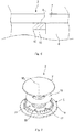
Fig. 4 zeigt die Einstelleinrichtung 11 in einem Ausgangszustand, in dem die Gasaustrittsöffnungen 10 einen größtmöglichen Öffnungsquerschnitt A10 aufweisen, und dieFig. 5 zeigt die Einstelleinrichtung 11 in einem Endzustand, in dem die Gasaustrittsöffnungen 10 einen minimal möglichen Öffnungsquerschnitt A10 aufweisen. - Die
Fig. 7 zeigt eine schematische perspektivische Explosionsansicht einer weiteren Ausführungsform eines Gasbrenners 2. DieFig. 8 zeigt eine schematische perspektivische Ansicht des Gasbrenners 2. DieFig. 9 zeigt eine schematische Schnittansicht des Gasbrenners 2 in einer Explosionsdarstellung und dieFig. 10 bis 12 zeigen jeweils weitere schematische Schnittansichten des Gasbrenners 2. Im Folgenden wird auf dieFig. 7 bis 12 gleichzeitig Bezug genommen. - Der Gasbrenner 2 umfasst das Brennergehäuse 5 mit dem Brennerunterteil 6 und dem oberseitig auf das Brennerunterteil 6 aufgelegten Brennerdeckel 7. An dem Brennerunterteil 6 sind Gasaustrittsöffnungen 10 mit einem jeweiligen variablen Öffnungsquerschnitt A10 vorgesehen. Die Einstelleinrichtung 11 weist im Gegensatz zu der Einstelleinrichtung 11 gemäß den
Fig. 2 bis 6 keine einzelnen Einstellkörper 12 auf, sondern ist als in der Mischkammer 9 angeordnete Scheibe ausgebildet. Das Brennerunterteil 6 umfasst eine Führungsscheibe 16, die in dem Brennerunterteil 6 aufgenommen ist. Die Führungsscheibe 16 weist eine Ausnehmung 17, insbesondere eine Bohrung auf, deren Mittelachse M17 parallel zu der Mittelachse M5 angeordnet ist. Es kann eine beliebige Anzahl an Ausnehmungen 17 vorgesehen sein. - Die Einstelleinrichtung 11 umfasst zu der Ausnehmung 17 oder zu den Ausnehmungen 17 korrespondierende stiftförmige Führungselemente 18, die linear in den Ausnehmungen 17 geführt sind. Beispielsweise können drei derartige Ausnehmungen 17 und drei derartige Führungselemente 18 vorgesehen sein. Da die scheibenförmige Einstelleinrichtung 11 in der Mischkammer 9 angeordnet ist, kann, wie in den
Fig. 10 bis 12 gezeigt, zusätzlich zu den Öffnungsquerschnitten A10 der Gasaustrittsöffnungen 10 auch ein Volumen der Mischkammer 9 mit Hilfe der Einstelleinrichtung 11 variiert werden. Insbesondere kann das Volumen wahlweise vergrößert oder verkleinert werden. - Mit Hilfe des Antriebselements 4 kann die Einstelleinrichtung 11, wie mit Hilfe eines Doppelpfeils 15 gezeigt, entlang der Mittelachse M5 verlagert werden, um die Öffnungsquerschnitte A10 der Gasaustrittsöffnungen 10 zu verkleinern oder zu vergrößern und um gleichzeitig das Volumen der Mischkammer 9 zu verkleinern oder zu vergrößern. Insbesondere ist das Antriebselement 4 derart mit dem jeweiligen Gasregelventil 3 gekoppelt, das die Einstelleinrichtung 11 dazu eingerichtet ist, die Öffnungsquerschnitte A10 der Gasaustrittsöffnungen 10 und das Volumen der Mischkammer 9 in Abhängigkeit von dem eingestellten Brenngasvolumenstrom zu variieren.
- Die
Fig. 13 zeigt eine schematische Explosionsansicht einer weiteren Ausführungsform eines Gasbrenners 2. DieFig. 14 zeigt eine weitere schematische Explosionsansicht des Gasbrenners 2. DieFig. 15 zeigt eine schematische perspektivische Ansicht des Gasbrenners 2. DieFig. 16 und 17 zeigen jeweils eine schematische Schnittansicht des Gasbrenners 2. DieFig. 18 und 19 zeigen jeweils schematische perspektivische Teilansichten des Gasbrenners 2. Im Folgenden wird auf dieFig. 13 bis 19 gleichzeitig Bezug genommen. - Der Gasbrenner 2 gemäß den
Fig. 13 bis 19 unterscheidet sich von dem Gasbrenner 2 gemäß derFig. 2 bis 6 und dem Gasbrenner 2 gemäß derFig. 7 bis 12 dadurch, dass die Einstelleinrichtung 11 nicht linear entlang der Mittelachse M5, sondern rotatorisch zu dieser verlagerbar ist. Das heißt, die Einstelleinrichtung 11 wird relativ zu dem Brennerunterteil 6 verdreht, um die Öffnungsquerschnitte A10 der Gasaustrittsöffnungen 10 zu variieren. - Die Einstelleinrichtung 11 weist hierzu einen scheibenförmigen Basisabschnitt 19 auf, an dem randseitig eine Vielzahl zahnartig angeordneter Einstellelemente 20 angeordnet ist, die je nach Relativposition der Einstelleinrichtung 11 gegenüber dem Brennerunterteil 6 die Gasaustrittsöffnungen 10 verdecken oder freigeben. Die
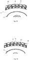
Fig. 18 zeigt die Einstelleinrichtung 11 hierzu in einem Ausgangszustand, in dem die Einstellelemente 20 die Gasaustrittsöffnungen 10 nicht verdecken und der jeweilige Öffnungsquerschnitt A10 der Gasaustrittsöffnungen 10 maximal ist. DieFig. 19 zeigt die Einstelleinrichtung 11 in einem Endzustand, in dem der jeweilige Öffnungsquerschnitt A10 der Gasaustrittsöffnungen 10 minimal ist. -
- 1
- Haushaltsgargerät
- 2
- Gasbrenner
- 3
- Gasregelventil
- 4
- Antriebselement
- 5
- Brennergehäuse
- 6
- Brennerunterteil
- 7
- Brennerdeckel
- 8
- Düsenkammer
- 9
- Mischkammer
- 10
- Gasaustrittsöffnung
- 11
- Einstelleinrichtung
- 12
- Einstellkörper
- 13
- Tragring
- 14
- Befestigungselement
- 15
- Doppelpfeil
- 16
- Führungsscheibe
- 17
- Ausnehmung
- 18
- Führungselement
- 19
- Basisabschnitt
- 20
- Einstellelement
- A10
- Öffnungsquerschnitt
- L
- Primärluft
- M5
- Mittelachse
- M17
- Mittelachse
- U
- Umgebung
Claims (15)
- Gasbrenner (2) für ein Haushaltsgargerät (1), mit einem Brennergehäuse (5), das zumindest eine Gasaustrittsöffnung (10) umfasst, die zur Flammenerzeugung mit einem Primärluft/Brenngas-Gemisch durchströmbar ist, und einer Einstelleinrichtung (11), die dazu eingerichtet ist, einen Öffnungsquerschnitt (A10) der zumindest einen Gasaustrittsöffnung (10) zu variieren.
- Gasbrenner (2) nach Anspruch 1, gekennzeichnet durch eine Vielzahl an Gasaustrittsöffnungen (10), wobei die Einstelleinrichtung (11) dazu eingerichtet ist, die Öffnungsquerschnitte (A10) aller Gasaustrittsöffnungen (10) gleichzeitig zu variieren.
- Gasbrenner (2) nach Anspruch 1 oder 2, dadurch gekennzeichnet, dass die Einstelleinrichtung (11) dazu eingerichtet ist, den Öffnungsquerschnitt (A10) der zumindest einen Gasaustrittsöffnung (10) wahlweise zu verkleinern oder zu vergrößern.
- Gasbrenner (2) nach einem der Ansprüche 1 - 3, dadurch gekennzeichnet, dass die Einstelleinrichtung (11) dazu eingerichtet ist, ein Volumen einer Mischkammer (9) des Gasbrenners (2) zu variieren, insbesondere wahlweise zu verkleinern oder zu vergrößern.
- Gasbrenner (2) nach einem der Ansprüche 1 - 4, dadurch gekennzeichnet, dass das Brennergehäuse (5) ein Brennerunterteil (6) und einen auf das Brennerunterteil (6) aufgelegten Brennerdeckel (7) aufweist, wobei die zumindest eine Gasaustrittsöffnung (10) an dem Brennerunterteil (6) vorgesehen ist.
- Gasbrenner (2) nach einem der Ansprüche 1 - 5, dadurch gekennzeichnet, dass die Einstelleinrichtung (11) zum Variieren des Öffnungsquerschnitts (A10) der zumindest einen Gasaustrittsöffnung (10) entlang einer Mittelachse (M5) des Brennergehäuses (5) linear verlagerbar ist.
- Gasbrenner (2) nach Anspruch 6, dadurch gekennzeichnet, dass die Einstelleinrichtung (11) einen Einstellkörper (12) aufweist, der in der zumindest einen Gasaustrittsöffnung (10) angeordnet ist und der zum Variieren des Öffnungsquerschnitts (A10) der zumindest einen Gasaustrittsöffnung (10) entlang der Mittelachse (M5) linear verlagerbar ist.
- Gasbrenner (2) nach Anspruch 7, dadurch gekennzeichnet, dass die Einstelleinrichtung (11) eine Vielzahl Einstellkörper (12), ein Befestigungselement (14) und einen Tragring (13) aufweist, wobei die Einstellkörper (12) gleichmäßig um einen Umfang des Tragrings (13) verteilt angeordnet und mit Hilfe des Befestigungselements (14) an dem Tragring (13) befestigt sind.
- Gasbrenner (2) nach einem der Ansprüche 6 - 8, dadurch gekennzeichnet, dass die Einstelleinrichtung (11) zumindest ein Führungselement (18) aufweist, das an einem Brennerunterteil (6) des Brennergehäuses (5) linear geführt ist.
- Gasbrenner (2) nach Anspruch 9, dadurch gekennzeichnet, dass das Führungselement (18) stiftförmig ist und dass das Führungselement (18) in einer an dem Brennerunterteil (6) vorgesehenen Ausnehmung (17) linear geführt ist.
- Gasbrenner (2) nach Anspruch 5, dadurch gekennzeichnet, dass die Einstelleinrichtung (11) zum Variieren des Öffnungsquerschnitts (A10) der zumindest einen Gasaustrittsöffnung (10) um eine Mittelachse (M5) des Brennergehäuses (5) drehbar ist.
- Gasbrenner (2) nach Anspruch 11, dadurch gekennzeichnet, dass die Einstelleinrichtung (11) einen ringförmigen Basisabschnitt (19) aufweist, an dem randseitig eine Vielzahl gleichmäßig über einen Umfang des Basisabschnitts (19) verteilte Einstellelemente (20) vorgesehen ist.
- Gasbrenner (2) nach einem der Ansprüche 1 - 12, dadurch gekennzeichnet, dass der Öffnungsquerschnitt (A10) der zumindest einen Gasaustrittsöffnung (10) rund oder rechteckig ist.
- Haushaltsgargerät (1), insbesondere Gasherd, mit einem Gasbrenner (2) nach einem der Ansprüche 1 - 13 und einem Gasregelventil (3) zum Einstellen eines Brenngasvolumenstroms zu dem Gasbrenner (2).
- Haushaltsgargerät (1) nach Anspruch 14, gekennzeichnet durch ein Antriebselement (4) zum Antreiben der Einstelleinrichtung (11), wobei das Antriebselement (4) derart mit dem Gasregelventil (3) gekoppelt ist, dass die Einstelleinrichtung (11) dazu eingerichtet ist, den zumindest einen Öffnungsquerschnitt (A10) in Abhängigkeit von dem Brenngasvolumenstrom zu variieren.
Applications Claiming Priority (1)
| Application Number | Priority Date | Filing Date | Title |
|---|---|---|---|
| ES201630764A ES2645964B1 (es) | 2016-06-07 | 2016-06-07 | Quemador de gas y aparato de cocción doméstico |
Publications (2)
| Publication Number | Publication Date |
|---|---|
| EP3255341A1 true EP3255341A1 (de) | 2017-12-13 |
| EP3255341B1 EP3255341B1 (de) | 2019-10-30 |
Family
ID=59021328
Family Applications (1)
| Application Number | Title | Priority Date | Filing Date |
|---|---|---|---|
| EP17173971.7A Active EP3255341B1 (de) | 2016-06-07 | 2017-06-01 | Gasbrenner und haushaltsgargerät |
Country Status (2)
| Country | Link |
|---|---|
| EP (1) | EP3255341B1 (de) |
| ES (1) | ES2645964B1 (de) |
Cited By (3)
| Publication number | Priority date | Publication date | Assignee | Title |
|---|---|---|---|---|
| CN109307266A (zh) * | 2018-08-16 | 2019-02-05 | 江西科明铜业有限公司 | 一种高效涡流式煤气灶燃烧器 |
| CN110848677A (zh) * | 2018-08-20 | 2020-02-28 | 宁波方太厨具有限公司 | 一种灶具燃烧器 |
| US11460190B2 (en) * | 2019-07-29 | 2022-10-04 | Haier Us Appliance Solutions, Inc. | Gas burner assembly for a cooktop appliance |
Families Citing this family (1)
| Publication number | Priority date | Publication date | Assignee | Title |
|---|---|---|---|---|
| CN110848676A (zh) * | 2018-08-20 | 2020-02-28 | 宁波方太厨具有限公司 | 一种灶具燃烧器 |
Citations (3)
| Publication number | Priority date | Publication date | Assignee | Title |
|---|---|---|---|---|
| GB1090426A (en) * | 1965-10-19 | 1967-11-08 | Parkinson Cowan Appliances Ltd | Gas burners |
| JPH09170722A (ja) * | 1995-12-19 | 1997-06-30 | Osaka Gas Co Ltd | 可変炎孔バーナ |
| BRPI1102895A2 (pt) * | 2011-06-14 | 2013-07-16 | Whirlpool Sa | queimador para equipamentos de cocÇço |
Family Cites Families (1)
| Publication number | Priority date | Publication date | Assignee | Title |
|---|---|---|---|---|
| JPH09280514A (ja) * | 1996-04-16 | 1997-10-31 | Paloma Ind Ltd | 全一次空気式バーナ |
-
2016
- 2016-06-07 ES ES201630764A patent/ES2645964B1/es not_active Expired - Fee Related
-
2017
- 2017-06-01 EP EP17173971.7A patent/EP3255341B1/de active Active
Patent Citations (3)
| Publication number | Priority date | Publication date | Assignee | Title |
|---|---|---|---|---|
| GB1090426A (en) * | 1965-10-19 | 1967-11-08 | Parkinson Cowan Appliances Ltd | Gas burners |
| JPH09170722A (ja) * | 1995-12-19 | 1997-06-30 | Osaka Gas Co Ltd | 可変炎孔バーナ |
| BRPI1102895A2 (pt) * | 2011-06-14 | 2013-07-16 | Whirlpool Sa | queimador para equipamentos de cocÇço |
Cited By (4)
| Publication number | Priority date | Publication date | Assignee | Title |
|---|---|---|---|---|
| CN109307266A (zh) * | 2018-08-16 | 2019-02-05 | 江西科明铜业有限公司 | 一种高效涡流式煤气灶燃烧器 |
| CN110848677A (zh) * | 2018-08-20 | 2020-02-28 | 宁波方太厨具有限公司 | 一种灶具燃烧器 |
| CN110848677B (zh) * | 2018-08-20 | 2023-06-20 | 宁波方太厨具有限公司 | 一种灶具燃烧器 |
| US11460190B2 (en) * | 2019-07-29 | 2022-10-04 | Haier Us Appliance Solutions, Inc. | Gas burner assembly for a cooktop appliance |
Also Published As
| Publication number | Publication date |
|---|---|
| ES2645964B1 (es) | 2018-09-20 |
| ES2645964A1 (es) | 2017-12-11 |
| EP3255341B1 (de) | 2019-10-30 |
Similar Documents
| Publication | Publication Date | Title |
|---|---|---|
| EP3255341B1 (de) | Gasbrenner und haushaltsgargerät | |
| DE69920193T2 (de) | Scheibe zur vermischung von brennstoff und luft für brennkammern mit mageren und geringem nox-ausstoss | |
| EP2290287A2 (de) | Brennerkappe für Gasherde und Gasherd-Brenner mit einer solchen Brennerkappe | |
| WO2018114490A1 (de) | Mischvorrichtung und brennerkopf für einen brenner mit reduziertem nox-ausstoss | |
| EP3465005B1 (de) | Gasbrenner und haushaltsgargerät | |
| DE3850935T2 (de) | Gas/luft-verhältnis-kontrollventil für gasbrenner. | |
| EP3479022B1 (de) | Gasbrenner und haushaltsgargerät | |
| DE4010093C1 (en) | Flame plug for IC-engine - has fuel metering insert and spaced evaporator tube to enclose heating bar | |
| EP3682165A1 (de) | Gasbrenner, gasbrenneranordnung und haushaltsgargerät | |
| DE2620424C2 (de) | Brennkammer mit variabler Geometrie der Luftzuführung für Gasturbinentriebwerke | |
| DE202008005913U1 (de) | Ölvormischbrenner | |
| DE4341126A1 (de) | Gas-Vormischbrenner | |
| DE2402997C3 (de) | Brenner für gasförmigen Brennstoff | |
| EP3012527A1 (de) | Gaskochstelle und kochfeld | |
| EP1067334B1 (de) | Gasbrenner für Geräte zum Garen von Nahrungsmitteln | |
| DE19744564C1 (de) | Gasbrenner für ein Brenngas-Primärluft-Gemisch | |
| DE2313126C3 (de) | Brenner für gasförmige Brennstoffe | |
| DE4420296C2 (de) | Gas-Luft-Verhältnisregler und dessen Verwendung in einer Gasbrennereinheit | |
| DE607253C (de) | Brenner fuer gas-, dampf-, staubfoermige oder fluessige Brennstoffe | |
| DE597106C (de) | Acetylenschlitzbrenner | |
| WO2016075580A1 (de) | Gasbrenner mit variablem lufteinlass und gaskochstelle | |
| EP1617142B1 (de) | Brenner | |
| EP1484554A1 (de) | Brenner mit mehreren überlappenden Brennersegmenten | |
| DE1916743A1 (de) | Blockgasbrenner | |
| DE1451583C (de) |
Legal Events
| Date | Code | Title | Description |
|---|---|---|---|
| PUAI | Public reference made under article 153(3) epc to a published international application that has entered the european phase |
Free format text: ORIGINAL CODE: 0009012 |
|
| STAA | Information on the status of an ep patent application or granted ep patent |
Free format text: STATUS: THE APPLICATION HAS BEEN PUBLISHED |
|
| AK | Designated contracting states |
Kind code of ref document: A1 Designated state(s): AL AT BE BG CH CY CZ DE DK EE ES FI FR GB GR HR HU IE IS IT LI LT LU LV MC MK MT NL NO PL PT RO RS SE SI SK SM TR |
|
| AX | Request for extension of the european patent |
Extension state: BA ME |
|
| STAA | Information on the status of an ep patent application or granted ep patent |
Free format text: STATUS: REQUEST FOR EXAMINATION WAS MADE |
|
| 17P | Request for examination filed |
Effective date: 20180613 |
|
| RBV | Designated contracting states (corrected) |
Designated state(s): AL AT BE BG CH CY CZ DE DK EE ES FI FR GB GR HR HU IE IS IT LI LT LU LV MC MK MT NL NO PL PT RO RS SE SI SK SM TR |
|
| GRAP | Despatch of communication of intention to grant a patent |
Free format text: ORIGINAL CODE: EPIDOSNIGR1 |
|
| STAA | Information on the status of an ep patent application or granted ep patent |
Free format text: STATUS: GRANT OF PATENT IS INTENDED |
|
| INTG | Intention to grant announced |
Effective date: 20190612 |
|
| GRAS | Grant fee paid |
Free format text: ORIGINAL CODE: EPIDOSNIGR3 |
|
| GRAA | (expected) grant |
Free format text: ORIGINAL CODE: 0009210 |
|
| STAA | Information on the status of an ep patent application or granted ep patent |
Free format text: STATUS: THE PATENT HAS BEEN GRANTED |
|
| AK | Designated contracting states |
Kind code of ref document: B1 Designated state(s): AL AT BE BG CH CY CZ DE DK EE ES FI FR GB GR HR HU IE IS IT LI LT LU LV MC MK MT NL NO PL PT RO RS SE SI SK SM TR |
|
| REG | Reference to a national code |
Ref country code: GB Ref legal event code: FG4D Free format text: NOT ENGLISH |
|
| REG | Reference to a national code |
Ref country code: CH Ref legal event code: EP |
|
| REG | Reference to a national code |
Ref country code: AT Ref legal event code: REF Ref document number: 1196556 Country of ref document: AT Kind code of ref document: T Effective date: 20191115 |
|
| REG | Reference to a national code |
Ref country code: DE Ref legal event code: R096 Ref document number: 502017002703 Country of ref document: DE |
|
| REG | Reference to a national code |
Ref country code: IE Ref legal event code: FG4D Free format text: LANGUAGE OF EP DOCUMENT: GERMAN |
|
| REG | Reference to a national code |
Ref country code: LT Ref legal event code: MG4D |
|
| PG25 | Lapsed in a contracting state [announced via postgrant information from national office to epo] |
Ref country code: SE Free format text: LAPSE BECAUSE OF FAILURE TO SUBMIT A TRANSLATION OF THE DESCRIPTION OR TO PAY THE FEE WITHIN THE PRESCRIBED TIME-LIMIT Effective date: 20191030 Ref country code: LV Free format text: LAPSE BECAUSE OF FAILURE TO SUBMIT A TRANSLATION OF THE DESCRIPTION OR TO PAY THE FEE WITHIN THE PRESCRIBED TIME-LIMIT Effective date: 20191030 Ref country code: PL Free format text: LAPSE BECAUSE OF FAILURE TO SUBMIT A TRANSLATION OF THE DESCRIPTION OR TO PAY THE FEE WITHIN THE PRESCRIBED TIME-LIMIT Effective date: 20191030 Ref country code: NO Free format text: LAPSE BECAUSE OF FAILURE TO SUBMIT A TRANSLATION OF THE DESCRIPTION OR TO PAY THE FEE WITHIN THE PRESCRIBED TIME-LIMIT Effective date: 20200130 Ref country code: FI Free format text: LAPSE BECAUSE OF FAILURE TO SUBMIT A TRANSLATION OF THE DESCRIPTION OR TO PAY THE FEE WITHIN THE PRESCRIBED TIME-LIMIT Effective date: 20191030 Ref country code: BG Free format text: LAPSE BECAUSE OF FAILURE TO SUBMIT A TRANSLATION OF THE DESCRIPTION OR TO PAY THE FEE WITHIN THE PRESCRIBED TIME-LIMIT Effective date: 20200130 Ref country code: PT Free format text: LAPSE BECAUSE OF FAILURE TO SUBMIT A TRANSLATION OF THE DESCRIPTION OR TO PAY THE FEE WITHIN THE PRESCRIBED TIME-LIMIT Effective date: 20200302 Ref country code: GR Free format text: LAPSE BECAUSE OF FAILURE TO SUBMIT A TRANSLATION OF THE DESCRIPTION OR TO PAY THE FEE WITHIN THE PRESCRIBED TIME-LIMIT Effective date: 20200131 Ref country code: LT Free format text: LAPSE BECAUSE OF FAILURE TO SUBMIT A TRANSLATION OF THE DESCRIPTION OR TO PAY THE FEE WITHIN THE PRESCRIBED TIME-LIMIT Effective date: 20191030 Ref country code: NL Free format text: LAPSE BECAUSE OF FAILURE TO SUBMIT A TRANSLATION OF THE DESCRIPTION OR TO PAY THE FEE WITHIN THE PRESCRIBED TIME-LIMIT Effective date: 20191030 |
|
| REG | Reference to a national code |
Ref country code: NL Ref legal event code: MP Effective date: 20191030 |
|
| PG25 | Lapsed in a contracting state [announced via postgrant information from national office to epo] |
Ref country code: HR Free format text: LAPSE BECAUSE OF FAILURE TO SUBMIT A TRANSLATION OF THE DESCRIPTION OR TO PAY THE FEE WITHIN THE PRESCRIBED TIME-LIMIT Effective date: 20191030 Ref country code: IS Free format text: LAPSE BECAUSE OF FAILURE TO SUBMIT A TRANSLATION OF THE DESCRIPTION OR TO PAY THE FEE WITHIN THE PRESCRIBED TIME-LIMIT Effective date: 20200229 Ref country code: RS Free format text: LAPSE BECAUSE OF FAILURE TO SUBMIT A TRANSLATION OF THE DESCRIPTION OR TO PAY THE FEE WITHIN THE PRESCRIBED TIME-LIMIT Effective date: 20191030 |
|
| PG25 | Lapsed in a contracting state [announced via postgrant information from national office to epo] |
Ref country code: AL Free format text: LAPSE BECAUSE OF FAILURE TO SUBMIT A TRANSLATION OF THE DESCRIPTION OR TO PAY THE FEE WITHIN THE PRESCRIBED TIME-LIMIT Effective date: 20191030 |
|
| PG25 | Lapsed in a contracting state [announced via postgrant information from national office to epo] |
Ref country code: CZ Free format text: LAPSE BECAUSE OF FAILURE TO SUBMIT A TRANSLATION OF THE DESCRIPTION OR TO PAY THE FEE WITHIN THE PRESCRIBED TIME-LIMIT Effective date: 20191030 Ref country code: RO Free format text: LAPSE BECAUSE OF FAILURE TO SUBMIT A TRANSLATION OF THE DESCRIPTION OR TO PAY THE FEE WITHIN THE PRESCRIBED TIME-LIMIT Effective date: 20191030 Ref country code: EE Free format text: LAPSE BECAUSE OF FAILURE TO SUBMIT A TRANSLATION OF THE DESCRIPTION OR TO PAY THE FEE WITHIN THE PRESCRIBED TIME-LIMIT Effective date: 20191030 Ref country code: DK Free format text: LAPSE BECAUSE OF FAILURE TO SUBMIT A TRANSLATION OF THE DESCRIPTION OR TO PAY THE FEE WITHIN THE PRESCRIBED TIME-LIMIT Effective date: 20191030 Ref country code: ES Free format text: LAPSE BECAUSE OF FAILURE TO SUBMIT A TRANSLATION OF THE DESCRIPTION OR TO PAY THE FEE WITHIN THE PRESCRIBED TIME-LIMIT Effective date: 20191030 |
|
| REG | Reference to a national code |
Ref country code: DE Ref legal event code: R097 Ref document number: 502017002703 Country of ref document: DE |
|
| PG25 | Lapsed in a contracting state [announced via postgrant information from national office to epo] |
Ref country code: SK Free format text: LAPSE BECAUSE OF FAILURE TO SUBMIT A TRANSLATION OF THE DESCRIPTION OR TO PAY THE FEE WITHIN THE PRESCRIBED TIME-LIMIT Effective date: 20191030 Ref country code: SM Free format text: LAPSE BECAUSE OF FAILURE TO SUBMIT A TRANSLATION OF THE DESCRIPTION OR TO PAY THE FEE WITHIN THE PRESCRIBED TIME-LIMIT Effective date: 20191030 |
|
| PLBE | No opposition filed within time limit |
Free format text: ORIGINAL CODE: 0009261 |
|
| STAA | Information on the status of an ep patent application or granted ep patent |
Free format text: STATUS: NO OPPOSITION FILED WITHIN TIME LIMIT |
|
| 26N | No opposition filed |
Effective date: 20200731 |
|
| PG25 | Lapsed in a contracting state [announced via postgrant information from national office to epo] |
Ref country code: SI Free format text: LAPSE BECAUSE OF FAILURE TO SUBMIT A TRANSLATION OF THE DESCRIPTION OR TO PAY THE FEE WITHIN THE PRESCRIBED TIME-LIMIT Effective date: 20191030 |
|
| REG | Reference to a national code |
Ref country code: DE Ref legal event code: R119 Ref document number: 502017002703 Country of ref document: DE |
|
| PG25 | Lapsed in a contracting state [announced via postgrant information from national office to epo] |
Ref country code: MC Free format text: LAPSE BECAUSE OF FAILURE TO SUBMIT A TRANSLATION OF THE DESCRIPTION OR TO PAY THE FEE WITHIN THE PRESCRIBED TIME-LIMIT Effective date: 20191030 |
|
| REG | Reference to a national code |
Ref country code: CH Ref legal event code: PL |
|
| PG25 | Lapsed in a contracting state [announced via postgrant information from national office to epo] |
Ref country code: LU Free format text: LAPSE BECAUSE OF NON-PAYMENT OF DUE FEES Effective date: 20200601 |
|
| REG | Reference to a national code |
Ref country code: BE Ref legal event code: MM Effective date: 20200630 |
|
| PG25 | Lapsed in a contracting state [announced via postgrant information from national office to epo] |
Ref country code: IE Free format text: LAPSE BECAUSE OF NON-PAYMENT OF DUE FEES Effective date: 20200601 Ref country code: FR Free format text: LAPSE BECAUSE OF NON-PAYMENT OF DUE FEES Effective date: 20200630 Ref country code: CH Free format text: LAPSE BECAUSE OF NON-PAYMENT OF DUE FEES Effective date: 20200630 Ref country code: LI Free format text: LAPSE BECAUSE OF NON-PAYMENT OF DUE FEES Effective date: 20200630 |
|
| PG25 | Lapsed in a contracting state [announced via postgrant information from national office to epo] |
Ref country code: DE Free format text: LAPSE BECAUSE OF NON-PAYMENT OF DUE FEES Effective date: 20210101 Ref country code: BE Free format text: LAPSE BECAUSE OF NON-PAYMENT OF DUE FEES Effective date: 20200630 |
|
| GBPC | Gb: european patent ceased through non-payment of renewal fee |
Effective date: 20210601 |
|
| PG25 | Lapsed in a contracting state [announced via postgrant information from national office to epo] |
Ref country code: GB Free format text: LAPSE BECAUSE OF NON-PAYMENT OF DUE FEES Effective date: 20210601 |
|
| PG25 | Lapsed in a contracting state [announced via postgrant information from national office to epo] |
Ref country code: MT Free format text: LAPSE BECAUSE OF FAILURE TO SUBMIT A TRANSLATION OF THE DESCRIPTION OR TO PAY THE FEE WITHIN THE PRESCRIBED TIME-LIMIT Effective date: 20191030 Ref country code: CY Free format text: LAPSE BECAUSE OF FAILURE TO SUBMIT A TRANSLATION OF THE DESCRIPTION OR TO PAY THE FEE WITHIN THE PRESCRIBED TIME-LIMIT Effective date: 20191030 |
|
| PG25 | Lapsed in a contracting state [announced via postgrant information from national office to epo] |
Ref country code: MK Free format text: LAPSE BECAUSE OF FAILURE TO SUBMIT A TRANSLATION OF THE DESCRIPTION OR TO PAY THE FEE WITHIN THE PRESCRIBED TIME-LIMIT Effective date: 20191030 |
|
| REG | Reference to a national code |
Ref country code: AT Ref legal event code: MM01 Ref document number: 1196556 Country of ref document: AT Kind code of ref document: T Effective date: 20220601 |
|
| PG25 | Lapsed in a contracting state [announced via postgrant information from national office to epo] |
Ref country code: AT Free format text: LAPSE BECAUSE OF NON-PAYMENT OF DUE FEES Effective date: 20220601 |
|
| PGFP | Annual fee paid to national office [announced via postgrant information from national office to epo] |
Ref country code: TR Payment date: 20250526 Year of fee payment: 9 |
|
| PGFP | Annual fee paid to national office [announced via postgrant information from national office to epo] |
Ref country code: IT Payment date: 20250630 Year of fee payment: 9 |