EP3255001A1 - Abwickelvorrichtung für ein band, wie etikettenband - Google Patents
Abwickelvorrichtung für ein band, wie etikettenband Download PDFInfo
- Publication number
- EP3255001A1 EP3255001A1 EP17000946.8A EP17000946A EP3255001A1 EP 3255001 A1 EP3255001 A1 EP 3255001A1 EP 17000946 A EP17000946 A EP 17000946A EP 3255001 A1 EP3255001 A1 EP 3255001A1
- Authority
- EP
- European Patent Office
- Prior art keywords
- rocker
- acting
- lever
- cam
- tape
- Prior art date
- Legal status (The legal status is an assumption and is not a legal conclusion. Google has not performed a legal analysis and makes no representation as to the accuracy of the status listed.)
- Granted
Links
Images



Classifications
-
- B—PERFORMING OPERATIONS; TRANSPORTING
- B65—CONVEYING; PACKING; STORING; HANDLING THIN OR FILAMENTARY MATERIAL
- B65H—HANDLING THIN OR FILAMENTARY MATERIAL, e.g. SHEETS, WEBS, CABLES
- B65H23/00—Registering, tensioning, smoothing or guiding webs
- B65H23/04—Registering, tensioning, smoothing or guiding webs longitudinally
- B65H23/06—Registering, tensioning, smoothing or guiding webs longitudinally by retarding devices, e.g. acting on web-roll spindle
-
- B—PERFORMING OPERATIONS; TRANSPORTING
- B65—CONVEYING; PACKING; STORING; HANDLING THIN OR FILAMENTARY MATERIAL
- B65H—HANDLING THIN OR FILAMENTARY MATERIAL, e.g. SHEETS, WEBS, CABLES
- B65H2402/00—Constructional details of the handling apparatus
- B65H2402/30—Supports; Subassemblies; Mountings thereof
-
- B—PERFORMING OPERATIONS; TRANSPORTING
- B65—CONVEYING; PACKING; STORING; HANDLING THIN OR FILAMENTARY MATERIAL
- B65H—HANDLING THIN OR FILAMENTARY MATERIAL, e.g. SHEETS, WEBS, CABLES
- B65H2402/00—Constructional details of the handling apparatus
- B65H2402/50—Machine elements
- B65H2402/54—Springs, e.g. helical or leaf springs
-
- B—PERFORMING OPERATIONS; TRANSPORTING
- B65—CONVEYING; PACKING; STORING; HANDLING THIN OR FILAMENTARY MATERIAL
- B65H—HANDLING THIN OR FILAMENTARY MATERIAL, e.g. SHEETS, WEBS, CABLES
- B65H2403/00—Power transmission; Driving means
- B65H2403/50—Driving mechanisms
- B65H2403/51—Cam mechanisms
-
- B—PERFORMING OPERATIONS; TRANSPORTING
- B65—CONVEYING; PACKING; STORING; HANDLING THIN OR FILAMENTARY MATERIAL
- B65H—HANDLING THIN OR FILAMENTARY MATERIAL, e.g. SHEETS, WEBS, CABLES
- B65H2403/00—Power transmission; Driving means
- B65H2403/70—Clutches; Couplings
- B65H2403/72—Clutches, brakes, e.g. one-way clutch +F204
- B65H2403/725—Brakes
-
- B—PERFORMING OPERATIONS; TRANSPORTING
- B65—CONVEYING; PACKING; STORING; HANDLING THIN OR FILAMENTARY MATERIAL
- B65H—HANDLING THIN OR FILAMENTARY MATERIAL, e.g. SHEETS, WEBS, CABLES
- B65H2404/00—Parts for transporting or guiding the handled material
- B65H2404/10—Rollers
- B65H2404/15—Roller assembly, particular roller arrangement
- B65H2404/152—Arrangement of roller on a movable frame
- B65H2404/1521—Arrangement of roller on a movable frame rotating, pivoting or oscillating around an axis, e.g. parallel to the roller axis
-
- B—PERFORMING OPERATIONS; TRANSPORTING
- B65—CONVEYING; PACKING; STORING; HANDLING THIN OR FILAMENTARY MATERIAL
- B65H—HANDLING THIN OR FILAMENTARY MATERIAL, e.g. SHEETS, WEBS, CABLES
- B65H2408/00—Specific machines
- B65H2408/20—Specific machines for handling web(s)
- B65H2408/21—Accumulators
- B65H2408/217—Accumulators of rollers type, e.g. with at least one fixed and one movable roller
-
- B—PERFORMING OPERATIONS; TRANSPORTING
- B65—CONVEYING; PACKING; STORING; HANDLING THIN OR FILAMENTARY MATERIAL
- B65H—HANDLING THIN OR FILAMENTARY MATERIAL, e.g. SHEETS, WEBS, CABLES
- B65H2515/00—Physical entities not provided for in groups B65H2511/00 or B65H2513/00
- B65H2515/30—Forces; Stresses
- B65H2515/32—Torque e.g. braking torque
-
- B—PERFORMING OPERATIONS; TRANSPORTING
- B65—CONVEYING; PACKING; STORING; HANDLING THIN OR FILAMENTARY MATERIAL
- B65H—HANDLING THIN OR FILAMENTARY MATERIAL, e.g. SHEETS, WEBS, CABLES
- B65H2701/00—Handled material; Storage means
- B65H2701/10—Handled articles or webs
- B65H2701/11—Dimensional aspect of article or web
- B65H2701/113—Size
- B65H2701/1133—Size of webs
- B65H2701/11332—Size of webs strip, tape, narrow web
-
- B—PERFORMING OPERATIONS; TRANSPORTING
- B65—CONVEYING; PACKING; STORING; HANDLING THIN OR FILAMENTARY MATERIAL
- B65H—HANDLING THIN OR FILAMENTARY MATERIAL, e.g. SHEETS, WEBS, CABLES
- B65H2701/00—Handled material; Storage means
- B65H2701/10—Handled articles or webs
- B65H2701/19—Specific article or web
- B65H2701/194—Web supporting regularly spaced adhesive articles, e.g. labels, rubber articles, labels or stamps
Definitions
- the invention relates to a unwinding device for a tape, such as a label tape, with a roller carrier, a pivotally mounted, elastically acted pendulum lever, which carries a guide roller at a free end, and with a braking device for the roller carrier, and with a pivotally mounted, elastically acted upon swingarm.
- Such unwinding devices are used on label printers, labellers and labellers.
- a carrier tape is pulled during unwinding via a first pendulum arm of a pivotally mounted, elastically preloaded pendulum lever (also called dancer arm).
- the pendulum lever generates a loop of tape, which is referred to as label memory.
- the label memory can be increased by the formation of further formed by guiding the band of partially also pivotally mounted pulleys formed loops.
- Label rolls usually consist of a roll core and the spiral wound on it carrier tape on which in turn labels are. The roll core is firmly clamped with a roller carrier of the unwinding device.
- a label memory is needed to decouple the sluggish label roll from the actual operation, such as printing or donations.
- the acceleration of the label roll from standstill and into standstill can take place much more slowly than the acceleration ramps of a printing or dispensing process require.
- the spring-loaded pendulum arm avoids jerky acceleration of the label roll.
- band brakes are used in such unwinding devices.
- the operation of this band brake is usually via an eccentric, which is in constant contact with the rocker of the band brake. There is a direct dependence on braking time and braking force.
- a brake wheel with the label roll rotatably connected and partially wrapped by a brake band the belt tension and thus the braking torque acting on the brake wheel is controlled by the position of the pendulum in such a way that the pendulum arm acts on a rocker arm via an eccentrically arranged control disc in that, under the tensile force of the springs acting on the pendulum arm, it pulls the brake band against the brake wheel against a spring acting on the rocker, the latter releasing the brake band when the band is applied to the pendulum arm by pulling. Therefore, acting on the rocker spring is used to release the brake band of the brake disc, while the force exerted on the brake disc via rocker and brake band force is effected directly by the springs acting on the pendulum.
- the object of the invention is not to use the force of the springs, which act on the pendulum lever, and these preloads, not for immediate actuation of the brake. Furthermore, the braking time and the braking force should be adjusted independently of each other, to print or label different width labels only the required to set lower or higher braking force.
- said object is achieved in a generic unwinding device characterized in that the rocker is pivotally pivotable under the elastic force acting on it, the roller carrier.
- the pendulum lever is pivotable against the elastic force acting on it when it acts on its free end bearing the deflection roller.
- the braking force caused by the rocker force transmitter caused by separate springs.
- the advantage is achieved that the force exerted by the rocker on the roller carrier and thus the label tape roll force is no longer biased by the pendulum lever springs must be effected, but is effected by the inventively provided separate associated with the rocker springs, so that the force acting on the pendulum lever bias and the brake voltage the swingarm can be selected or adjusted independently of each other.
- an eccentrically arranged on the pendulum lever cam over which the rocker is pivotable provided.
- a further embodiment provides that the rocker is pivotable by the cam of the pendulum lever against the elastic force acting on it.
- a preferred development of the device according to the invention provides that the pendulum lever can be pivoted against the elastic tension acting on it when the force acting on its free end carrying the deflection roller.
- the device according to the invention is characterized in that a braking effect on the roller carrier can be exercised by the elastic tension acting on the rocker. Also provides a preferred development beyond that by pivoting the Rocker due to the movement of the cam of the pendulum lever against the elastic force acting on the rocker release of the roller carrier or a release of the braking effect acting on it is effected.
- a preferred embodiment provides that the pivot lever is formed with two arms and the cam is arranged on another arm than the deflection roller.
- the arranged on the second of the pulley arm of the pivot lever arranged cam pivot the rocker against the spring force acting on this to release the braking effect, if on the pulley for the label tape at its free end bearing arm of the pivot lever, the withdrawal force of the label tape (causes by acting on this triggering device) acts.
- the cam engages in a recess of the rocker, wherein the recess of the rocker is a slot, in particular an oval slot.
- the on the one hand on the pivot lever, on the other hand on the rocker, acting elastic stresses or forces are preferably generated by the fact that the pivot lever and / or rocker pressure exerted by at least one spring, in particular by at least one coil spring causes.
- the cam is angularly adjustable about the axis of the pivot lever. As a result, the braking time can be adjusted. It is further provided that the elastic force acting on the rocker is variable, in particular by changing the spring force and / or number of acting on the rocker elastic force springs.
- Fig. 1 shows the essential elements of a unwinding device 1 for a label tape.
- the unwinding device has a rotatably mounted roller carrier 2 and a plate 3 fixedly connected thereto on one side with a circular outer contour. This acts as a contact surface for a label roll R, which is formed by a wound on a roll core K spiral label tape B.
- the roller core K is rotatably clamped to the roller carrier 2 and clamped in the operating state rotationally fixed.
- the label tape B consists of a carrier tape on which labels are glued to each other at a slight distance.
- the unwinding device 1 further comprises a first, stationary, but rotatably mounted guide roller 4 and an elastically biased pendulum lever 5, at one, in the Fig. 1 visible end 5.1 of an arm 5.2, a further guide roller 6 is rotatably mounted.
- the unwinding device 1 is part of a labeling machine or a label printer, which - not shown - further guide or deflection rollers, a motor-driven removal device, by means of which the tape B is withdrawn from the roll R, a label dispensing device for transferring the labels located on the tape to a product to be labeled, and optionally may have a label printer for printing the labels.
- the pendulum lever 5 in a position in which no forces are exerted on this by the band B or acting on this trigger force, so for example at standstill of the device, wherein it acts on the pendulum lever 5 and elastic bias (hereinafter will be explained in more detail).
- the double length between the guide roller 4 and guide roller 6 in the illustrated unloaded position of the pivot arm 5 is referred to as - maximum - label memory.
- a withdrawal force is applied intermittently and during the transfer of the labels and possibly also the printing of the same is the tape at the printing or transfer point at a standstill.
- the role R due to the inertia caused by their inertia at standstill continue to roll, so that there is a risk that when rolling beyond the maximum size of the label memory E out the tape between roll R and take-off point is no longer under tension, but rather is held loose and can run in curves or loops. With another deduction by the trigger then there is a risk that the tape is torn.
- the Fig. 2 shows the back of the unwinding device 1 and first turn the plate 3 and the pendulum lever 5 with the guide roller 6 at the free end 5.1 of a first lever arm 5.2 of the pendulum lever 5.
- the device 1 has a housing 7, on which all other parts directly or indirectly, are pivotally or rotatably mounted, so the plate 3 and with him the roller carrier 2 about a central pivot axis A1.
- the roller carrier 2 has on in the Fig. 2 shown back of the plate 3 a neck 2.1 with also a circular outer contour.
- the others also in the Fig. 2 shown parts of the unwinding device 1 according to the invention will be described in more detail below with reference to the FIG. 3 to FIG. 5 explained.
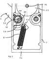
- the Fig. 3 shows in relation to the Fig. 2 enlarged view of the seen from the rear behind in the Fig. 2 visible elements in a lower level other elements, such as the pendulum lever 5, which is mounted about a pivot axis A2.
- the pendulum lever 5 is formed with two arms already with reference to the Fig. 1 mentioned lever arm 5.2 and a relative to the axis of rotation A2 diametrically opposed pivot lever 5.3.
- the cam 5.4 is angularly adjustable to adjust the braking time about the axis A2 with its central axis, for example, from a position A4 in a position A4 '- as in Fig. 3 shown.
- first coil springs 8 engage the lever arm 5.3 of the pivot lever 5 - in the illustrated embodiment - two first coil springs 8, which are attached to a lower cross member 7.1 of the housing 7.
- the first springs 8 can be seen pulling the pivot lever 5 in the in the Fig. 1 to Fig. 3 shown position in which the lever arm 5.2 is pulled upward and the lever arm 5.3 under the action of the springs 8 down.
- the cam 5.4 is in a lower position - compared to a position in which the pivot lever 5 and the lever arm 5.2 is pulled under a withdrawal force of the belt B down, causing the lever arm 5.3 and thus the cam 5.4 against the action of Springs 8 is pivoted upwards.
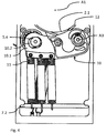
- the Figure 4 shows a in the rear view shown there front plane opposite to the Fig. 3 located rocker 10 which is pivotally mounted about a pivot axis A3.
- the rocker 10 points in the region of a free end 10.1 a slot in which engages the cam 5.4 of the pendulum lever 5.
- the rocker 10 holds between its axis of rotation A3 and its end portion 10.1 with slot 10.2 and attack location of the second springs 10, a brake band 12 which is guided around the neck 2.1 of the roller carrier.
- the braking device 9 (the Fig. 4 ) is in the Figure 5 again for clarity as such, solved by other parts of the unwinding shown in perspective. For explanation, reference is made to the above description.
Landscapes
- Labeling Devices (AREA)
Abstract
Description
- Die Erfindung betrifft eine Abwickelvorrichtung für ein Band, wie ein Etikettenband, mit einem Rollenträger, einem schwenkbar gelagerten, elastisch beaufschlagten Pendelhebel, der an einem freien Ende eine Umlenkrolle trägt, und mit einer Bremsvorrichtung für den Rollenträger, und mit einer schwenkbar gelagerten, elastisch beaufschlagten Schwinge.
- Solche Abwickelvorrichtungen werden an Etikettendruckern, Etikettiergeräten und Etikettiermaschinen verwendet. Ein Trägerband wird beim Abwickeln über einen ersten Pendelarm eines schwenkbar gelagerten, elastisch vorgespannten Pendelhebels (auch Tänzerarm genannt) gezogen. Der Pendelhebel erzeugt eine Schlaufe des Bandes, welche als Etikettenspeicher bezeichnet wird. Der Etikettenspeicher kann durch die Bildung weiterer durch Führung des Bandes von teilweise ebenfalls schwenkbar gelagerter Umlenkrollen gebildeter Schlaufen vergrößert werden. Etikettenrollen bestehen meist aus einem Rollenkern und dem darauf spiralförmig aufgewickelten Trägerband, auf welchem sich wiederum Etiketten befinden. Der Rollenkern ist fest mit einem Rollenträger der Abwickelvorrichtung verspannbar.
- Grundsätzlich wird ein Etikettenspeicher benötigt, um die träge Etikettenrolle vom eigentlichen Arbeitsvorgang, zum Beispiel Drucken oder Spenden, zu entkoppeln. Durch diese Entkopplung kann die Beschleunigung der Etikettenrolle aus dem Stillstand und in den Stillstand sehr viel langsamer erfolgen als die Beschleunigungsrampen eines Druck- oder Spendevorganges dies erfordern. Durch den gefederten Pendelarm wird eine ruckartige Beschleunigung der Etikettenrolle vermieden.
- Insbesondere bei hohen Geschwindigkeiten ist eine gleichmäßige Spannung in dem Trägerband anzustreben und ein ruckartiger Anstieg der Spannung in dem Trägerband zu vermeiden, um ein gutes Druckergebnis bzw. ein gutes Etikettierergebnis zu erreichen.
- Bei bekannten Abwickelvorrichtungen steuert die Stellung des Pendelhebels eine Bremse, welche bei einem geringen Etikettenspeicher geöffnet ist und bei einem gefüllten Etikettenspeicher unter Federkraft geschlossen ist.
- Üblicherweise werden in solchen Abwickelvorrichtungen Bandbremsen verwendet. Die Betätigung dieser Bandbremse erfolgt in der Regel über einen Exzenter, der im ständigen Kontakt mit der Schwinge der Bandbremse ist. Es besteht eine direkte Abhängigkeit von Bremszeitpunkt und Bremskraft.
- Die Energie zum Betätigen dieser Bandbremse wird bisher aus dem Arbeitsvermögen der Feder bzw. den Federn des Pendelhebels geholt. Somit wird das Arbeitsvermögen der Federn des Pendelhebels, je nach Belastung, in den Bremsvorgang und in die Bewegung des Pendelhebels aufgeteilt.
- Dies gilt auch für die gattungsgemäße Abwickelvorrichtung mit einer Bremse zur Abwicklung eines Etikettenbandes oder dergleichen von einer Etikettenrolle nach der
DE 20 2006 005 557 U1 . Bei dieser Vorrichtung ist ein federbeaufschlagter Pendelarm an einem Gehäuse angelegt. Der Pendelarm ist zur Führung des Etikettenbandes ausgebildet. Er steuert durch seine Lage die Zugspannung in diesem Etikettenband. Hierzu ist ein Bremsrad mit der Etikettenrolle drehfest verbunden und bereichsweise von einem Bremsband umschlungen, dessen Bandspannung und damit das auf das Bremsrad wirkende Bremsmoment von der Stellung des Pendelarms gesteuert ist und zwar derart, dass der Pendelarm über eine exzentrisch angeordnete Steuerscheibe auf eine Schwinge derart wirkt, dass diese unter der Zugkraft der am Pendelarm angreifenden Federn das Bremsband gegen das Bremsrad entgegen einer an der Schwinge angreifenden Feder zieht, die letztere bei Zugausübung durch das Etikettenband auf den Pendelarm das Bremsband freigibt. Die an der Schwinge angreifende Feder dient daher zum Lösen des Bremsbandes von der Bremsscheibe, während die auf die Bremsscheibe über Schwinge und Bremsband ausgeübte Kraft unmittelbar durch die am Pendelarm angreifenden Federn bewirkt wird. - Aufgabe der Erfindung ist es, die Kraft der Federn, welche am Pendelhebel angreifen, und diesen Vorspannen, nicht zum unmittelbaren Betätigen der Bremse zu verwenden. Weiterhin sollen Bremszeitpunkt und die Bremskraft unabhängig voneinander einzustellen sein, um beim Bedrucken oder Etikettieren von unterschiedlich breiten Etiketten lediglich die benötigte geringere bzw. höhere Bremskraft einstellen zu müssen.
- Erfindungsgemäß wird die genannte Aufgabe bei einer gattungsgemäßen Abwickelvorrichtung dadurch gelöst, die Schwinge unter der auf sie einwirkenden elastischen Kraft den Rollenträger bremsend verschwenkbar ist.
- Durch die erfindungsgemäße Ausgestaltung einer Abwickelvorrichtung mit einer vom Schwenkhebel separaten, wenn auch mit diesem verbundenen, unter der auf sie wirkenden elastischen Kraft eine Bremsung bewirkenden Schwinge wird folgendes erreicht: Bei auf den Schwenkhebel durch den Zug des Etikettenbandes ausgeübte "Schwenkkräfte" wird die Schwinge in eine Freigabeposition, in der keine Bremsung erfolgt, aktiv bewegt, während bei Stillstand des Bandes der insofern elastisch beaufschlagte Schwenkhebel in eine Position gebracht wird, in der er die Schwinge über den Nocken mitnimmt und in der über andere als am Schwenkhebel wirksame Kräfte die Schwinge so eine Bremsung bewirkt. Hierzu können separate, beispielsweise aktiv wirkende Komponenten vorgesehen sein.
- In bevorzugter Ausgestaltung ist ein exzentrisch am Pendelhebel angeordneter Nocken, über den die Schwinge verschwenkbar ist, vorgesehen, wobei insbesondere die Schwinge durch den Nocken des Pendelhebels entgegen der auf sie wirkenden elastischen Kraft verschwenkbar ist. Auch sieht eine bevorzugte Weiterbildung vor, dass der Pendelhebel bei Krafteinwirkung auf sein die Umlenkrolle tragendes freies Ende entgegen der auf ihn wirkenden elastischen Spannung verschwenkbar ist.
- Bevorzugt werden die die Bremsung durch die Schwinge verursachenden Kraftgeber durch separate Federn bewirkt. Durch diese vorgespannte, an der Schwinge angreifende und durch eine Exzenter-Nocken-Verbindung zwischen Pendelhebel und der die Bremsung bewirkenden Schwinge wird der Vorteil erreicht, dass die durch die Schwinge auf den Rollenträger und damit die Etikettenbandrolle ausgeübte Kraft nicht mehr durch den Pendelhebel vorspannende Federn bewirkt werden muss, sondern durch die erfindungsgemäß vorgesehenen separaten der Schwinge zugeordneten Federn bewirkt wird, so dass die auf den Pendelhebel wirkende Vorspannung und die Bremsspannung
der Schwinge unabhängig voneinander gewählt oder eingestellt werden können. - In einer ersten bevorzugten Ausgestaltung der erfindungsgemäßen Vorrichtung ist ein exzentrisch am Pendelhebel angeordneter Nocken, über den die Schwinge verschwenkbar ist, vorgesehen. Eine Weiterbildung sieht vor, dass die Schwinge durch den Nocken des Pendelhebels entgegen der auf sie wirkenden elastischen Kraft verschwenkbar ist.
- Eine bevorzugte Weiterbildung der erfindungsgemäßen Vorrichtung sieht vor, dass der Pendelhebel bei Krafteinwirkung auf sein die Umlenkrolle tragendes freies Ende entgegen der auf ihn wirkenden elastischen Spannung verschwenkbar ist.
- In weiterer Ausgestaltung zeichnet sich die erfindungsgemäße Vorrichtung dadurch aus, dass durch die auf die Schwinge wirkende elastische Spannung eine Bremswirkung auf den Rollenträger ausübbar ist. Auch sieht eine bevorzugte Weiterbildung darüber hinaus vor, dass durch Verschwenken der Schwinge aufgrund der Bewegung des Nockens des Pendelhebels entgegen der auf die Schwinge wirkenden elastischen Spannung eine Freigabe des Rollenträgers bzw. ein Lösen der auf diesen wirkenden Bremswirkung bewirkt wird.
- Die Übertragung der das Bremsen bewirkenden Schwingenbewegung unter Einfluss der an dieser angreifenden Federn wird in an sich bekannter Weise durch ein an der Schwinge befestigtes um einen Ansatz des Rollenträgers geführtes Bremsband erreicht.
- Weiterhin sieht eine bevorzugte Ausgestaltung vor, dass der Schwenkhebel zweiarmig ausgebildet ist und der Nocken an einem anderen Arm als die Umlenkrolle angeordnet ist. Hierdurch kann der am zweiten der Umlenkrolle abgewandten Arm des Schwenkhebels angeordnete Nocken die Schwinge entgegen der auf diese wirkende Federkraft zum Lösen der Bremswirkung schwenkend anheben, wenn auf den die Umlenkrolle für das Etikettenband an seinem freien Ende tragenden Arm des Schwenkhebels die Abzugkraft des Etikettenbandes (bewirkt durch eine an diesem angreifende Abzugsvorrichtung) einwirkt.
- In weiterer bevorzugter Ausgestaltung ist vorgesehen, dass der Nocken in eine Ausnehmung der Schwinge eingreift, wobei die Ausnehmung der Schwinge ein Langloch, insbesondere ein ovales Langloch ist. Hierdurch können die einerseits Nocken, andererseits Langloch-Ausnehmung, tragenden Enden von Schwenkhebel bzw. Schwingen über die Schwenkbewegung beider eine relative radiale Bewegung ausführen, so dass es zu keiner Blockade kommt.
- Die einerseits auf den Schwenkhebel, andererseits auf die Schwinge, einwirkenden elastischen Spannungen oder Kräfte werden in bevorzugter Weise dadurch erzeugt, dass die auf Schwenkhebel und/oder Schwinge ausgeübte Spannung jeweils durch mindestens eine Feder, insbesondere durch jeweils mindestens eine Schraubenfeder, bewirkt wird.
- In bevorzugter Ausgestaltung ist vorgesehen, dass der Nocken angular um die Achse des Schwenkhebels verstellbar ist. Hierdurch kann der Bremszeitpunkt eingestellt werden. Weiterhin ist vorgesehen, dass die an der Schwinge angreifende elastische Kraft veränderbar ist, insbesondere durch Änderung der Federkraft und/oder Anzahl der die auf die Schwinge wirkende elastische Kraft bewirkenden Federn.
- Weitere Vorteile und Merkmale der Erfindung ergeben sich aus den Ansprüchen und aus der nachfolgenden Beschreibung, in der ein Ausführungsbeispiel der Erfindung unter Bezugnahme auf die Zeichnung im Einzelnen erläutert ist. Dabei zeigt:
- Fig. 1
- eine schematische Vorderansicht einer Abwickelvorrichtung;
- Fig. 2
- die Rückseite einer bevorzugten Ausgestaltung der erfindungsgemäßen Abwickelvorrichtung;
- Fig. 3
- eine Rückseitendarstellung mit entfernter Schwinge und Bandbremse zur Wiedergabe der Ebene hinter dieser mit Lagerung und Spannungsbeaufschlagung des Pendelhebels;
- Fig. 4
- eine vergrößerte Ausschnittdarstellung der Rückansicht der
Fig. 2 mit Schwinge und Bandbremse; - Fig. 5
- eine separate perspektivische Darstellung der eigentlichen Bremsvorrichtung mit Schwinge, Bremsband und die Schwinge beaufschlagenden Federn; und
-
Fig. 1 zeigt die wesentlichen Elemente einer Abwickelvorrichtung 1 für ein Etikettenband. Die Abwickelvorrichtung weist einen drehbar gelagerten Rollenträger 2 sowie einen einseitig mit diesem fest verbundenen Teller 3 mit kreisförmiger Außenkontur auf. Dieser wirkt als Anlagefläche für eine Etikettenrolle R, die durch ein auf einem Rollenkern K spiralig aufgewickeltes Etikettenband B gebildet ist. Der Rollenkern K ist mit dem Rollenträger 2 drehfest verspannbar und im Betriebszustand drehfest verspannt. Das Etikettenband B besteht aus einem Trägerband, auf dem mit geringfügigem Abstand zueinander Etiketten aufgeklebt sind. - Die Abwickelvorrichtung 1 weist ferner eine erste, ortsfest, aber drehbar gelagerte Umlenkrolle 4 sowie einen elastisch vorgespannten Pendelhebel 5 auf, an dessen einem, in der
Fig. 1 sichtbaren Ende 5.1 eines Arms 5.2 eine weitere Umlenkrolle 6 drehbar gelagert ist. - Die Abwickelvorrichtung 1 ist Teil einer Etikettiermaschine oder eines Etikettendruckers, der - nicht dargestellt - weitere Führungs- oder Umlenkrollen, eine motorisch angetriebene Abzugsvorrichtung, mittels derer das Band B von der Rolle R abgezogen wird, eine Etikettenspendeeinrichtung zum Übergeben der auf dem Band befindlichen Etiketten auf ein zu etikettierendes Produkt aufweist sowie gegebenenfalls einen Etikettendrucker zum Bedrucken der Etiketten aufweisen kann.
- Im dargestellten Ausführungsbeispiel der
Fig. 1 befindet sich der Pendelhebel 5 in einer Stellung, bei welcher auf diesen durch das Band B bzw. die auf dieses wirkende Abzugskraft keine Kräfte ausgeübt werden, also beispielsweise im Stillstand der Vorrichtung, wobei sie auf den Pendelhebel 5 sowie elastischen Vorspannung einwirkt (die im Weiteren noch näher erläutert wird). - Die doppelte Länge zwischen Umlenkrolle 4 und Umlenkrolle 6 in der dargestellten entlasteten Position des Schwenkarms 5 wird als - maximaler - Etikettenspeicher bezeichnet.
- Wird das Etikettenband B durch die nicht gezeigte motorische Abzugs- oder Fördereinrichtung gefördert und damit die Rolle R abgewickelt, so wirkt auf den elastisch gelagerten Pendelhebel 5 eine Abzugskraft des Bandes, welche diesen Pendelhebel 5 gegen die auf die ihn wirkenden elastischen Spannungen oder Kräfte aus der in
Fig. 1 dargestellten Position nach unten bewegt, je nach einwirkender Abzugskraft bis maximal auf die Höhe der festgelagerten Umlenkrolle 4, wodurch das Speichervermögen des Etikettenspeichers E bzw. dieser selbst damit auf Null reduziert ist. - Bei einer Etikettiermaschine oder einem Etikettendrucker wird eine Abzugskraft intermittierend ausgeübt und während der Übergabe der Etiketten und gegebenenfalls auch dem Bedrucken derselben findet sich das Band am Druck- bzw. Übergabeort im Stillstand. Bei einer freidrehend gelagerten Rolle R bzw. einem entsprechend frei drehbar gelagerten Rollenträger 2 kann die Rolle R aufgrund der durch ihre Masse bedingten Trägheit beim Stillstand weiter abrollen, so dass die Gefahr besteht, dass beim Abrollen über die Maximalgröße des Etikettenspeichers E hinaus das Band zwischen Rolle R und Abzugsstelle nicht mehr unter Spannung steht, sondern vielmehr locker gehalten ist und in Kurven oder Schlaufen verlaufen kann. Bei erneutem Abzug durch die Abzugsvorrichtung besteht dann die Gefahr, dass das Band zerrissen wird.
- Aus diesem Grunde wird regemäßig eine auf den Rollenträger 2 und damit die Rolle R bei Nachlassen der auf den Pendelhebel 5 wirkenden Bandspannung eine mit diesem verbundene automatisch wirkende Bremsvorrichtung vorgesehen.
- Die bevorzugte erfindungsgemäße Ausgestaltung einer solchen Bremsvorrichtung wird im Weiteren beschrieben.
- Die
Fig. 2 zeigt die Rückseite der Abwickelvorrichtung 1 und zunächst wiederum den Teller 3 und den Pendelhebel 5 mit der Umlenkrolle 6 am freien Ende 5.1 eines ersten Hebelarms 5.2 des Pendelhebels 5. Die Vorrichtung 1 weist ein Gehäuse 7 auf, an dem alle weiteren Teile direkt oder indirekt, schwenk- bzw. drehbar befestigt sind, so der Teller 3 und mit ihm der Rollenträger 2 um eine zentrale Schwenkachse A1. Der Rollenträger 2 hat auf der in derFig. 2 dargestellten Rückseite des Tellers 3 einen Ansatz 2.1 mit ebenfalls einer kreisförmigen Außenkontur. Die weiteren auch in derFig. 2 dargestellten Teile der erfindungsgemäßen Abwickelvorrichtung 1 werden im Folgenden näher unter Bezug auf dieFig. 3 bis Fig. 5 erläutert. - Die
Fig. 3 zeigt in gegenüber derFig. 2 vergrößerter Darstellung die von Rückseite aus gesehen hinter den in derFig. 2 sichtbaren Elementen in einer tieferen Ebene befindlichen weiteren Elemente, so insbesondere den Pendelhebel 5, der um eine Schwenkachse A2 gelagert ist. Der Pendelhebel 5 ist zweiarmig ausgebildet mit dem schon unter Bezug auf dieFig. 1 erwähnten Hebelarm 5.2 und einem relativ zur Drehachse A2 diametral gegenüberliegenden Schwenkhebel 5.3. Am Schwenkhebel 5.3 ist exzentrisch zur Schwenkachse A2 ein Exzenter-Nocken 5.4 am Hebelarm 5.3 vorgesehen. Der Nocken 5.4 ist zur Einstellung des Bremszeitpunkts um die Achse A2 mit seiner Mittelachse angular verstellbar, beispielsweise aus einer Position A4 in eine Position A4' - wie inFig. 3 dargestellt. - Weiterhin greifen am Hebelarm 5.3 des Schwenkhebels 5 - im dargestellten Ausführungsbeispiel - zwei erste Schraubenfedern 8 an, die an einem unteren Querträger 7.1 des Gehäuses 7 befestigt sind. Die ersten Federn 8 ziehen ersichtlich den Schwenkhebel 5 in die in den
Fig. 1 bis Fig. 3 dargestellte Position, bei der der Hebelarm 5.2 nach oben und der Hebelarm 5.3 unter Einwirkung der Federn 8 nach unten gezogen ist. Damit befindet sich auch der Nocken 5.4 in einer unteren Position - gegenüber einer Position, bei der der Schwenkhebel 5 bzw. der Hebelarm 5.2 unter einer Abzugskraft des Bandes B nach unten gezogen ist, wodurch der Hebelarm 5.3 und damit der Nocken 5.4 entgegen der Wirkung der Federn 8 nach oben geschwenkt wird. - Die
Fig.4 zeigt eine in der dort dargestellten Rückseitenansicht vorderen Ebene gegenüber derFig. 3 befindliche Schwinge 10, die um eine Schwenkachse A3 schwenkbar gelagert ist. Die Schwinge 10 weist im Bereich eines freien Endes 10.1 ein Langloch auf, in welches der Nocken 5.4 des Pendelhebels 5 eingreift. Ebenfalls im Bereich ihres freien Endes 10.1 greifen an der Schwinge 10 - bei der dargestellten Ausführungsform - drei zweite Schraubenfedern 11 an, die an ihrem unteren Ende wiederum am Gestell 7 und zwar an einem Querträger 7.2 befestigt sind. - Die Schwinge 10 hält zwischen ihrer Drehachse A3 und ihrem Endbereich 10.1 mit Langloch 10.2 und Angreifort der zweiten Federn 10 ein Bremsband 12, welches um den Ansatz 2.1 des Rollenträgers herumgeführt ist. Die Bremsvorrichtung 9 (der
Fig. 4 ) ist in derFig.5 noch einmal zur Verdeutlichung als solche, gelöst von weiteren Teilen der Abwickelvorrichtung perspektivisch dargestellt. Zur Erläuterung wird auf die vorstehende Beschreibung verwiesen. - Befindet sich der Pendelhebel 5 in seiner in den
Fig. 1 bis Fig. 3 dargestellten durch die elastische Spannung der ersten Federn 8 bewirkten oberen Stellung des ersten Hebelarms 5.2, wenn durch das Etikettenband B keine Abzugskraft aus ihm ausgeübt wird, so befindet sich sein zweiter Hebelarm 5.3 und damit der Nocken 5.4 in der in derFig. 3 dargestellten unteren Stellung und demgemäß auch das freie Ende 10.1 der Schwinge 10 in einer durch die Spannung der zweiten Federn 11 bewirkten unteren Stellung. Damit wird das an der Schwinge 10 befestigte Bremsband 12 gegen den Ansatz 2.1 des Rollenträgers 2 gezogen und somit auf diesen und die drehfest auf ihm aufsitzende Etikettenbandrolle R eine Bremswirkung ausgeübt, so dass diese in Stillstand gebracht und gehalten wird, auch entgegen einer nachlaufenden Drehbewegung aufgrund der Trägheit der Rolle R, wenn vorher ein Bandabzug erfolgt ist. - Wird nun eine Zugkraft auf das Etikettenband B - durch die nicht dargestellte Abzugsvorrichtung - ausgeübt, so wird der freie Arm 5.2 des Pendelhebels 5 durch diese Zugkraft nach unten bewegt. Der zweite Hebelarm 5.3 des Pendelhebels 5 hebt sich nach oben entgegen der auf diesen wirkenden Spannung der ersten Federn 8 und damit bewegt sich auch der Nocken 5.4 nach oben, der in das Langloch 10.2 der Schwinge 10 eingreift; dieser hebt derart entgegen der auf die Schwinge 10 einwirkenden Spannung der zweiten Federn 11 das freie Ende 10.1 der Schwinge 10 in einer Schwenkbewegung um die Schwenkachse A3 nach oben, wodurch das Bremsband 12 vom Ansatz 2.1 des Rollenträgers 2 gelöst wird und damit sich die Etikettenbandrolle R unter der am Band B angreifenden Abzugskraft sich frei drehen und Bandlänge abgeben kann.
- Fällt bei Stillstand der Abzugsbewegung die Abzugskraft auf den Schwenkhebel 5 wieder fort, so wird in der im vorletzten Absatz beschriebenen Weise wieder die Bremswirkung auf die Etikettenbandrolle R ausgeübt, so dass diese nicht unter ihrer Trägheit nachlaufen kann und das Etikettenband B weiterhin unter der - auch durch den Pendelhebel 5 - bewirkte Spannung straff gespannt bleibt.
Claims (13)
- Abwickelvorrichtung für ein Band, wie ein Etikettenband, mit einem Rollenträger (2), einem schwenkbar gelagerten, elastisch beaufschlagten Pendelhebel (5), der an einem freien Ende (5.1) eine Umlenkrolle (6) trägt, mit einer Bremsvorrichtung (9) für den Rollenträger (2), und mit einer schwenkbar gelagerten, elastisch beaufschlagten Schwinge (10)
dadurch gekennzeichnet, dass
die Schwinge (10) unter der auf sie einwirkenden elastischen Kraft den Rollenträger (2) bremsend verschwenkbar ist. - Vorrichtung nach Anspruch 1, gekennzeichnet durch einen exzentrisch am Pendelhebel (5) angeordneten Nocken (5.4), über den die Schwinge (10) verschwenkbar ist.
- Vorrichtung nach Anspruch 1 oder 2, dadurch gekennzeichnet, dass die Schwinge (10) durch den Nocken (5.4) des Pendelhebels (5) entgegen der auf sie wirkenden elastischen Kraft verschwenkbar ist.
- Vorrichtung nach einem der vorangehenden Ansprüche, dadurch gekennzeichnet, dass der Pendelhebel (5) bei Krafteinwirkung auf sein die Umlenkrolle (6) tragendes freies Ende (5.1) entgegen der auf ihn wirkenden elastischen Spannung verschwenkbar ist.
- Vorrichtung nach einem der vorangehenden Ansprüche, dadurch gekennzeichnet, dass durch die auf die Schwinge (10) wirkende elastische Spannung eine Bremswirkung auf den Rollenträger (2) ausübbar ist.
- Vorrichtung nach einem der vorangehenden Ansprüche, dadurch gekennzeichnet, dass durch Verschwenken der Schwinge (10) aufgrund der Bewegung des Nockens (5.4) des Pendelhebels (5) entgegen der auf die Schwinge (10) wirkenden elastischen Spannung eine Freigabe des Rollenträgers (2) bzw. ein Lösen der auf diesen wirkenden Bremswirkung bewirkt wird.
- Vorrichtung nach einem der vorangehenden Ansprüche, gekennzeichnet durch ein an der Schwinge (10) befestigtes um einen Ansatz (2.1) des Rollenträgers (2) geführtes Bremsband (12).
- Vorrichtung nach einem der vorangehenden Ansprüche, dadurch gekennzeichnet, dass der Schwenkhebel (2) zweiarmig ausgebildet ist und der Nocken (5.4) an einem anderen Arm (5.3) als die Umlenkrolle (6) angeordnet ist.
- Vorrichtung nach einem der vorangehenden Ansprüche, dadurch gekennzeichnet, dass der Nocken (5.4) in eine Ausnehmung (10.2) der Schwinge (10) eingreift.
- Vorrichtung nach Anspruch 9, dadurch gekennzeichnet, dass die Ausnehmung (10.2) der Schwinge (10) ein Langloch, insbesondere ein ovales Langloch ist.
- Vorrichtung nach einem der vorangehenden Ansprüche, dadurch gekennzeichnet, dass die auf Schwenkhebel (5) und/oder Schwinge (10) ausgeübte Spannung jeweils durch mindestens eine Feder, insbesondere durch jeweils mindestens eine Schraubenfeder (8; 11), bewirkt wird.
- Vorrichtung nach einem der Ansprüche 2 bis 11, dadurch gekennzeichnet, dass der Nocken (5.4) angular um die Achse (A2) des Schwenkhebels (5) verstellbar ist.
- Vorrichtung nach einem der vorangehenden Ansprüche, dadurch gekennzeichnet, dass die an der Schwinge (10) angreifende elastische Kraft veränderbar ist, insbesondere durch Änderung der Federkraft und/oder Anzahl der die auf die Schwinge (10) wirkende elastische Kraft bewirkenden Federn.
Applications Claiming Priority (1)
| Application Number | Priority Date | Filing Date | Title |
|---|---|---|---|
| DE102016006747.0A DE102016006747A1 (de) | 2016-06-06 | 2016-06-06 | Abwickelvorrichtung für ein Band, wie Etikettenband |
Publications (2)
| Publication Number | Publication Date |
|---|---|
| EP3255001A1 true EP3255001A1 (de) | 2017-12-13 |
| EP3255001B1 EP3255001B1 (de) | 2022-07-20 |
Family
ID=59014424
Family Applications (1)
| Application Number | Title | Priority Date | Filing Date |
|---|---|---|---|
| EP17000946.8A Active EP3255001B1 (de) | 2016-06-06 | 2017-06-02 | Abwickelvorrichtung für ein band, wie etikettenband |
Country Status (2)
| Country | Link |
|---|---|
| EP (1) | EP3255001B1 (de) |
| DE (1) | DE102016006747A1 (de) |
Cited By (2)
| Publication number | Priority date | Publication date | Assignee | Title |
|---|---|---|---|---|
| US12679126B2 (en) | 2024-07-31 | 2026-07-14 | Brady Worldwide, Inc. | Printhead opening system and method |
| US12697829B2 (en) | 2024-07-31 | 2026-08-04 | Brady Worldwide, Inc. | Printhead force adjust and lift system and method |
Families Citing this family (1)
| Publication number | Priority date | Publication date | Assignee | Title |
|---|---|---|---|---|
| DE102019214964B4 (de) * | 2019-09-30 | 2024-05-16 | Multivac Sepp Haggenmüller Se & Co. Kg | Folienaufnahmevorrichtung sowie Verfahren zum Abwickeln einer Folienrolle |
Citations (4)
| Publication number | Priority date | Publication date | Assignee | Title |
|---|---|---|---|---|
| CH624911A5 (en) * | 1978-01-27 | 1981-08-31 | Sodeco Compteurs De Geneve | Unreeling device for a material strip wound on a supply roll |
| GB2345692A (en) * | 1999-01-16 | 2000-07-19 | Thorn Secure Science Ltd | Apparatus to maintain the tension of an elongate flexible feedstock includes a moveable roller linked to a brake |
| DE202006005557U1 (de) | 2006-03-30 | 2007-08-09 | Herma Gmbh | Abwickelvorrichtung mit einer Bremse |
| CN102372104A (zh) * | 2010-08-26 | 2012-03-14 | 天津北科精工自动化科技发展有限责任公司 | 凸轮控制的摩擦式恒张力机构 |
Family Cites Families (2)
| Publication number | Priority date | Publication date | Assignee | Title |
|---|---|---|---|---|
| BE538276A (de) * | 1954-09-06 | |||
| US3083602A (en) * | 1961-01-13 | 1963-04-02 | West Virginia Pulp & Paper Co | Precise web metering device |
-
2016
- 2016-06-06 DE DE102016006747.0A patent/DE102016006747A1/de not_active Withdrawn
-
2017
- 2017-06-02 EP EP17000946.8A patent/EP3255001B1/de active Active
Patent Citations (4)
| Publication number | Priority date | Publication date | Assignee | Title |
|---|---|---|---|---|
| CH624911A5 (en) * | 1978-01-27 | 1981-08-31 | Sodeco Compteurs De Geneve | Unreeling device for a material strip wound on a supply roll |
| GB2345692A (en) * | 1999-01-16 | 2000-07-19 | Thorn Secure Science Ltd | Apparatus to maintain the tension of an elongate flexible feedstock includes a moveable roller linked to a brake |
| DE202006005557U1 (de) | 2006-03-30 | 2007-08-09 | Herma Gmbh | Abwickelvorrichtung mit einer Bremse |
| CN102372104A (zh) * | 2010-08-26 | 2012-03-14 | 天津北科精工自动化科技发展有限责任公司 | 凸轮控制的摩擦式恒张力机构 |
Cited By (2)
| Publication number | Priority date | Publication date | Assignee | Title |
|---|---|---|---|---|
| US12679126B2 (en) | 2024-07-31 | 2026-07-14 | Brady Worldwide, Inc. | Printhead opening system and method |
| US12697829B2 (en) | 2024-07-31 | 2026-08-04 | Brady Worldwide, Inc. | Printhead force adjust and lift system and method |
Also Published As
| Publication number | Publication date |
|---|---|
| DE102016006747A1 (de) | 2017-12-07 |
| EP3255001B1 (de) | 2022-07-20 |
Similar Documents
| Publication | Publication Date | Title |
|---|---|---|
| EP2794036B1 (de) | Rückhaltevorrichtung, insbesondere für trainingszwecke | |
| DE10113197B4 (de) | Vereinzelungsvorrichtung, insbesondere in einem Bilderzeugungsgerät | |
| WO2012045381A1 (de) | Vorrichtung zur drahtzuführung an drahtverarbeitungsmaschinen | |
| EP3255001B1 (de) | Abwickelvorrichtung für ein band, wie etikettenband | |
| EP0958734B1 (de) | Rundballenpresse für landwirtschaftliches Erntegut. | |
| DE3933453A1 (de) | Gurtaufroller | |
| EP0477498B1 (de) | Einrichtung zum Aufwickeln von Druckereiprodukten | |
| DE3035114A1 (de) | Vorrichtung zum herstellen von schuppenbandrollen aus geschuppt uebereinanderliegenden flachen werkstuecken | |
| DE891268C (de) | Kraftangetriebene Papierwagenaufzugsvorrichtung fuer Schreibmaschinen u. dgl. | |
| DE3033746A1 (de) | Aufrollautomat fuer einen sicherheitsgurt | |
| WO2007065710A1 (de) | Tänzerarm für konstante zugspannung | |
| EP0049376B1 (de) | Rollenträger | |
| DE102010041057B4 (de) | Bremsförderrolle mit Hemmregler | |
| EP1119510A1 (de) | Wickelvorrichtung für flexible flächengebilde, insbesondere druckereiprodukte | |
| DE2502213A1 (de) | Vorrichtung zum mechanischen ziehen von kabeln | |
| DE2253179A1 (de) | Kontinuierlich arbeitende abwickelvorrichtung | |
| DE1035231B (de) | Bandzugsteuervorrichtung fuer eine Maschine zum Bewickeln elektrischer Kabel | |
| DE102013015866B4 (de) | Abrollsystem für eine Rolle Papier sowie für eine Füllmaterialfertigungsmaschine | |
| DE559529C (de) | Papierfuehrungsvorrichtung an Schreibmaschinen | |
| DE7322061U (de) | Etikettiermaschine für selbstklebende Abziehetiketten | |
| DE245778C (de) | ||
| DE973549C (de) | Stoppvorrichtung fuer Buchungsmaschinen-Zaehlwerktrommel | |
| EP3216730B1 (de) | Vorrichtung zum abwickeln oder aufwickeln einer materialbahn von einem bzw. auf einen wickelkern | |
| DE2107115C3 (de) | Vorrichtung zum Ausrollen der Kanten und Führen einer laufenden Warenbahn | |
| DE102013200609A1 (de) | Intelligente Laufrolle mit Funktion zum Freirollen |
Legal Events
| Date | Code | Title | Description |
|---|---|---|---|
| PUAI | Public reference made under article 153(3) epc to a published international application that has entered the european phase |
Free format text: ORIGINAL CODE: 0009012 |
|
| STAA | Information on the status of an ep patent application or granted ep patent |
Free format text: STATUS: THE APPLICATION HAS BEEN PUBLISHED |
|
| AK | Designated contracting states |
Kind code of ref document: A1 Designated state(s): AL AT BE BG CH CY CZ DE DK EE ES FI FR GB GR HR HU IE IS IT LI LT LU LV MC MK MT NL NO PL PT RO RS SE SI SK SM TR |
|
| AX | Request for extension of the european patent |
Extension state: BA ME |
|
| STAA | Information on the status of an ep patent application or granted ep patent |
Free format text: STATUS: REQUEST FOR EXAMINATION WAS MADE |
|
| 17P | Request for examination filed |
Effective date: 20180612 |
|
| RBV | Designated contracting states (corrected) |
Designated state(s): AL AT BE BG CH CY CZ DE DK EE ES FI FR GB GR HR HU IE IS IT LI LT LU LV MC MK MT NL NO PL PT RO RS SE SI SK SM TR |
|
| STAA | Information on the status of an ep patent application or granted ep patent |
Free format text: STATUS: EXAMINATION IS IN PROGRESS |
|
| 17Q | First examination report despatched |
Effective date: 20201201 |
|
| GRAP | Despatch of communication of intention to grant a patent |
Free format text: ORIGINAL CODE: EPIDOSNIGR1 |
|
| STAA | Information on the status of an ep patent application or granted ep patent |
Free format text: STATUS: GRANT OF PATENT IS INTENDED |
|
| INTG | Intention to grant announced |
Effective date: 20220331 |
|
| GRAS | Grant fee paid |
Free format text: ORIGINAL CODE: EPIDOSNIGR3 |
|
| GRAA | (expected) grant |
Free format text: ORIGINAL CODE: 0009210 |
|
| STAA | Information on the status of an ep patent application or granted ep patent |
Free format text: STATUS: THE PATENT HAS BEEN GRANTED |
|
| AK | Designated contracting states |
Kind code of ref document: B1 Designated state(s): AL AT BE BG CH CY CZ DE DK EE ES FI FR GB GR HR HU IE IS IT LI LT LU LV MC MK MT NL NO PL PT RO RS SE SI SK SM TR |
|
| REG | Reference to a national code |
Ref country code: CH Ref legal event code: EP |
|
| REG | Reference to a national code |
Ref country code: DE Ref legal event code: R096 Ref document number: 502017013477 Country of ref document: DE |
|
| REG | Reference to a national code |
Ref country code: AT Ref legal event code: REF Ref document number: 1505430 Country of ref document: AT Kind code of ref document: T Effective date: 20220815 |
|
| REG | Reference to a national code |
Ref country code: IE Ref legal event code: FG4D Free format text: LANGUAGE OF EP DOCUMENT: GERMAN |
|
| REG | Reference to a national code |
Ref country code: LT Ref legal event code: MG9D |
|
| REG | Reference to a national code |
Ref country code: NL Ref legal event code: MP Effective date: 20220720 |
|
| PG25 | Lapsed in a contracting state [announced via postgrant information from national office to epo] |
Ref country code: SE Free format text: LAPSE BECAUSE OF FAILURE TO SUBMIT A TRANSLATION OF THE DESCRIPTION OR TO PAY THE FEE WITHIN THE PRESCRIBED TIME-LIMIT Effective date: 20220720 Ref country code: RS Free format text: LAPSE BECAUSE OF FAILURE TO SUBMIT A TRANSLATION OF THE DESCRIPTION OR TO PAY THE FEE WITHIN THE PRESCRIBED TIME-LIMIT Effective date: 20220720 Ref country code: PT Free format text: LAPSE BECAUSE OF FAILURE TO SUBMIT A TRANSLATION OF THE DESCRIPTION OR TO PAY THE FEE WITHIN THE PRESCRIBED TIME-LIMIT Effective date: 20221121 Ref country code: NO Free format text: LAPSE BECAUSE OF FAILURE TO SUBMIT A TRANSLATION OF THE DESCRIPTION OR TO PAY THE FEE WITHIN THE PRESCRIBED TIME-LIMIT Effective date: 20221020 Ref country code: NL Free format text: LAPSE BECAUSE OF FAILURE TO SUBMIT A TRANSLATION OF THE DESCRIPTION OR TO PAY THE FEE WITHIN THE PRESCRIBED TIME-LIMIT Effective date: 20220720 Ref country code: LV Free format text: LAPSE BECAUSE OF FAILURE TO SUBMIT A TRANSLATION OF THE DESCRIPTION OR TO PAY THE FEE WITHIN THE PRESCRIBED TIME-LIMIT Effective date: 20220720 Ref country code: LT Free format text: LAPSE BECAUSE OF FAILURE TO SUBMIT A TRANSLATION OF THE DESCRIPTION OR TO PAY THE FEE WITHIN THE PRESCRIBED TIME-LIMIT Effective date: 20220720 Ref country code: FI Free format text: LAPSE BECAUSE OF FAILURE TO SUBMIT A TRANSLATION OF THE DESCRIPTION OR TO PAY THE FEE WITHIN THE PRESCRIBED TIME-LIMIT Effective date: 20220720 Ref country code: ES Free format text: LAPSE BECAUSE OF FAILURE TO SUBMIT A TRANSLATION OF THE DESCRIPTION OR TO PAY THE FEE WITHIN THE PRESCRIBED TIME-LIMIT Effective date: 20220720 |
|
| PG25 | Lapsed in a contracting state [announced via postgrant information from national office to epo] |
Ref country code: PL Free format text: LAPSE BECAUSE OF FAILURE TO SUBMIT A TRANSLATION OF THE DESCRIPTION OR TO PAY THE FEE WITHIN THE PRESCRIBED TIME-LIMIT Effective date: 20220720 Ref country code: IS Free format text: LAPSE BECAUSE OF FAILURE TO SUBMIT A TRANSLATION OF THE DESCRIPTION OR TO PAY THE FEE WITHIN THE PRESCRIBED TIME-LIMIT Effective date: 20221120 Ref country code: HR Free format text: LAPSE BECAUSE OF FAILURE TO SUBMIT A TRANSLATION OF THE DESCRIPTION OR TO PAY THE FEE WITHIN THE PRESCRIBED TIME-LIMIT Effective date: 20220720 Ref country code: GR Free format text: LAPSE BECAUSE OF FAILURE TO SUBMIT A TRANSLATION OF THE DESCRIPTION OR TO PAY THE FEE WITHIN THE PRESCRIBED TIME-LIMIT Effective date: 20221021 |
|
| REG | Reference to a national code |
Ref country code: DE Ref legal event code: R097 Ref document number: 502017013477 Country of ref document: DE |
|
| PG25 | Lapsed in a contracting state [announced via postgrant information from national office to epo] |
Ref country code: SM Free format text: LAPSE BECAUSE OF FAILURE TO SUBMIT A TRANSLATION OF THE DESCRIPTION OR TO PAY THE FEE WITHIN THE PRESCRIBED TIME-LIMIT Effective date: 20220720 Ref country code: RO Free format text: LAPSE BECAUSE OF FAILURE TO SUBMIT A TRANSLATION OF THE DESCRIPTION OR TO PAY THE FEE WITHIN THE PRESCRIBED TIME-LIMIT Effective date: 20220720 Ref country code: DK Free format text: LAPSE BECAUSE OF FAILURE TO SUBMIT A TRANSLATION OF THE DESCRIPTION OR TO PAY THE FEE WITHIN THE PRESCRIBED TIME-LIMIT Effective date: 20220720 Ref country code: CZ Free format text: LAPSE BECAUSE OF FAILURE TO SUBMIT A TRANSLATION OF THE DESCRIPTION OR TO PAY THE FEE WITHIN THE PRESCRIBED TIME-LIMIT Effective date: 20220720 |
|
| PLBE | No opposition filed within time limit |
Free format text: ORIGINAL CODE: 0009261 |
|
| STAA | Information on the status of an ep patent application or granted ep patent |
Free format text: STATUS: NO OPPOSITION FILED WITHIN TIME LIMIT |
|
| PG25 | Lapsed in a contracting state [announced via postgrant information from national office to epo] |
Ref country code: SK Free format text: LAPSE BECAUSE OF FAILURE TO SUBMIT A TRANSLATION OF THE DESCRIPTION OR TO PAY THE FEE WITHIN THE PRESCRIBED TIME-LIMIT Effective date: 20220720 Ref country code: EE Free format text: LAPSE BECAUSE OF FAILURE TO SUBMIT A TRANSLATION OF THE DESCRIPTION OR TO PAY THE FEE WITHIN THE PRESCRIBED TIME-LIMIT Effective date: 20220720 |
|
| P01 | Opt-out of the competence of the unified patent court (upc) registered |
Effective date: 20230516 |
|
| 26N | No opposition filed |
Effective date: 20230421 |
|
| PG25 | Lapsed in a contracting state [announced via postgrant information from national office to epo] |
Ref country code: AL Free format text: LAPSE BECAUSE OF FAILURE TO SUBMIT A TRANSLATION OF THE DESCRIPTION OR TO PAY THE FEE WITHIN THE PRESCRIBED TIME-LIMIT Effective date: 20220720 |
|
| PGFP | Annual fee paid to national office [announced via postgrant information from national office to epo] |
Ref country code: DE Payment date: 20230629 Year of fee payment: 7 |
|
| PG25 | Lapsed in a contracting state [announced via postgrant information from national office to epo] |
Ref country code: SI Free format text: LAPSE BECAUSE OF FAILURE TO SUBMIT A TRANSLATION OF THE DESCRIPTION OR TO PAY THE FEE WITHIN THE PRESCRIBED TIME-LIMIT Effective date: 20220720 |
|
| PGFP | Annual fee paid to national office [announced via postgrant information from national office to epo] |
Ref country code: AT Payment date: 20230616 Year of fee payment: 7 |
|
| PGFP | Annual fee paid to national office [announced via postgrant information from national office to epo] |
Ref country code: CH Payment date: 20230727 Year of fee payment: 7 |
|
| PG25 | Lapsed in a contracting state [announced via postgrant information from national office to epo] |
Ref country code: MC Free format text: LAPSE BECAUSE OF FAILURE TO SUBMIT A TRANSLATION OF THE DESCRIPTION OR TO PAY THE FEE WITHIN THE PRESCRIBED TIME-LIMIT Effective date: 20220720 |
|
| PG25 | Lapsed in a contracting state [announced via postgrant information from national office to epo] |
Ref country code: MC Free format text: LAPSE BECAUSE OF FAILURE TO SUBMIT A TRANSLATION OF THE DESCRIPTION OR TO PAY THE FEE WITHIN THE PRESCRIBED TIME-LIMIT Effective date: 20220720 |
|
| REG | Reference to a national code |
Ref country code: BE Ref legal event code: MM Effective date: 20230630 |
|
| GBPC | Gb: european patent ceased through non-payment of renewal fee |
Effective date: 20230602 |
|
| PG25 | Lapsed in a contracting state [announced via postgrant information from national office to epo] |
Ref country code: LU Free format text: LAPSE BECAUSE OF NON-PAYMENT OF DUE FEES Effective date: 20230602 |
|
| REG | Reference to a national code |
Ref country code: IE Ref legal event code: MM4A |
|
| PG25 | Lapsed in a contracting state [announced via postgrant information from national office to epo] |
Ref country code: LU Free format text: LAPSE BECAUSE OF NON-PAYMENT OF DUE FEES Effective date: 20230602 |
|
| PG25 | Lapsed in a contracting state [announced via postgrant information from national office to epo] |
Ref country code: IE Free format text: LAPSE BECAUSE OF NON-PAYMENT OF DUE FEES Effective date: 20230602 |
|
| PG25 | Lapsed in a contracting state [announced via postgrant information from national office to epo] |
Ref country code: IE Free format text: LAPSE BECAUSE OF NON-PAYMENT OF DUE FEES Effective date: 20230602 Ref country code: GB Free format text: LAPSE BECAUSE OF NON-PAYMENT OF DUE FEES Effective date: 20230602 |
|
| PG25 | Lapsed in a contracting state [announced via postgrant information from national office to epo] |
Ref country code: IT Free format text: LAPSE BECAUSE OF FAILURE TO SUBMIT A TRANSLATION OF THE DESCRIPTION OR TO PAY THE FEE WITHIN THE PRESCRIBED TIME-LIMIT Effective date: 20220720 Ref country code: BE Free format text: LAPSE BECAUSE OF NON-PAYMENT OF DUE FEES Effective date: 20230630 |
|
| PG25 | Lapsed in a contracting state [announced via postgrant information from national office to epo] |
Ref country code: BG Free format text: LAPSE BECAUSE OF FAILURE TO SUBMIT A TRANSLATION OF THE DESCRIPTION OR TO PAY THE FEE WITHIN THE PRESCRIBED TIME-LIMIT Effective date: 20220720 |
|
| PG25 | Lapsed in a contracting state [announced via postgrant information from national office to epo] |
Ref country code: BG Free format text: LAPSE BECAUSE OF FAILURE TO SUBMIT A TRANSLATION OF THE DESCRIPTION OR TO PAY THE FEE WITHIN THE PRESCRIBED TIME-LIMIT Effective date: 20220720 |
|
| REG | Reference to a national code |
Ref country code: DE Ref legal event code: R119 Ref document number: 502017013477 Country of ref document: DE |
|
| REG | Reference to a national code |
Ref country code: CH Ref legal event code: PL |
|
| REG | Reference to a national code |
Ref country code: AT Ref legal event code: MM01 Ref document number: 1505430 Country of ref document: AT Kind code of ref document: T Effective date: 20240602 |
|
| PG25 | Lapsed in a contracting state [announced via postgrant information from national office to epo] |
Ref country code: DE Free format text: LAPSE BECAUSE OF NON-PAYMENT OF DUE FEES Effective date: 20250101 |
|
| PG25 | Lapsed in a contracting state [announced via postgrant information from national office to epo] |
Ref country code: AT Free format text: LAPSE BECAUSE OF NON-PAYMENT OF DUE FEES Effective date: 20240602 Ref country code: CH Free format text: LAPSE BECAUSE OF NON-PAYMENT OF DUE FEES Effective date: 20240630 |
|
| PGFP | Annual fee paid to national office [announced via postgrant information from national office to epo] |
Ref country code: FR Payment date: 20250512 Year of fee payment: 9 |
|
| PG25 | Lapsed in a contracting state [announced via postgrant information from national office to epo] |
Ref country code: CY Free format text: LAPSE BECAUSE OF FAILURE TO SUBMIT A TRANSLATION OF THE DESCRIPTION OR TO PAY THE FEE WITHIN THE PRESCRIBED TIME-LIMIT; INVALID AB INITIO Effective date: 20170602 |
|
| PG25 | Lapsed in a contracting state [announced via postgrant information from national office to epo] |
Ref country code: HU Free format text: LAPSE BECAUSE OF FAILURE TO SUBMIT A TRANSLATION OF THE DESCRIPTION OR TO PAY THE FEE WITHIN THE PRESCRIBED TIME-LIMIT; INVALID AB INITIO Effective date: 20170602 |
|
| PG25 | Lapsed in a contracting state [announced via postgrant information from national office to epo] |
Ref country code: TR Free format text: LAPSE BECAUSE OF FAILURE TO SUBMIT A TRANSLATION OF THE DESCRIPTION OR TO PAY THE FEE WITHIN THE PRESCRIBED TIME-LIMIT Effective date: 20220720 |